

Page 1
Variable Frequency Drive
DISCONTINUED
For Reference Only
Field Installation
Installation, Operation and Maintenance Manual
Effective December 2018
***Interactive PDF***
Page 2

Installation, Operation and Maintenance Manual
Field Installed Variable Frequency Drives (VFD’s
Contents
Important Notice ����������������������������������������������������������������������������������������������������� 3
Use of Symbols ������������������������������������������������������������������������������������������������������ 3
ELECTRICAL HAZARD ������������������������������������������������������������������������������������������ 3
WARNING �������������������������������������������������������������������������������������������������������������� 3
CAUTION ��������������������������������������������������������������������������������������������������������������� 3
INFORMATION ������������������������������������������������������������������������������������������������������� 3
General Information ������������������������������������������������������������������������������������������������ 4
Inspection of Equipment ����������������������������������������������������������������������������������������� 4
Handling ����������������������������������������������������������������������������������������������������������������� 4
Location ������������������������������������������������������������������������������������������������������������������ 4
Programming ���������������������������������������������������������������������������������������������������������� 4
Voltage Unbalance �������������������������������������������������������������������������������������������������5
Field Provided VFD / Field Installed ����������������������������������������������������������������������� 6
Field Provided VFD / Field Installed (Continued) ��������������������������������������������������� 7
Static Pressure Transducer ������������������������������������������������������������������������������ 7
Field or Factory Provided/Field Installed ���������������������������������������������������������� 7
Field Provided VFD / Field Installed (Continued) ��������������������������������������������� 8
Factory Provided VFD / Field Installed ������������������������������������������������������������������� 9
Field Provided VFD / Field Installed (Continued) ������������������������������������������� 10
LIMITED WARRANTY ������������������������������������������������������������������������������������ 12
FACTORY TESTED ��������������������������������������������������������������������������������������� 12
Subject to change without notice. 120.7-IM (1218)
2
Page 3

Installation, Operation and Maintenance Manual
Field Installed Variable Frequency Drives (VFD’s
Important Notice
This manual is the property of the owner.
Please be sure to leave it with the owner when you leave the job.
Use of Symbols
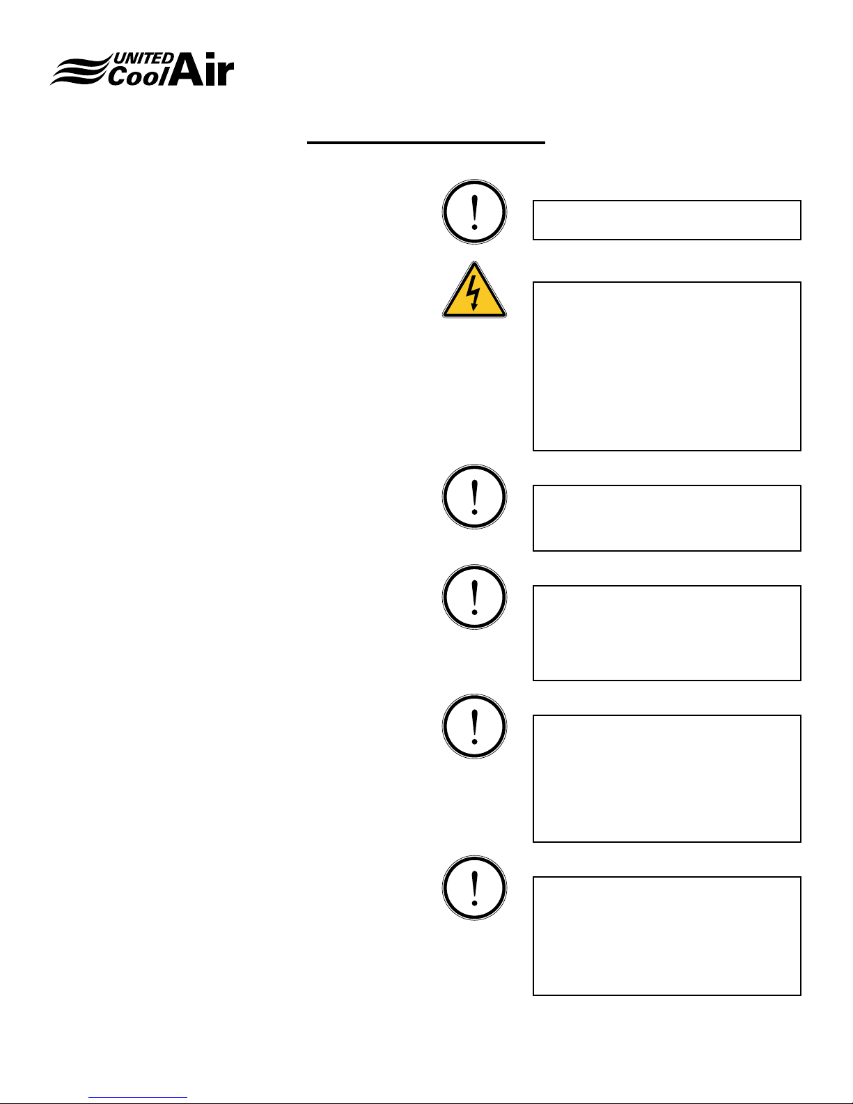
This publication includes warnings, cautions and information icons that point out safety related issues or conditions as well
as other pertinent information relative to a safe installation, service or maintenance situation� The following icons should be
interpreted as follows:
ELECTRICAL
HAZARD
WARNING
CAUTION
INFORMATION
The electrical hazard icon indicates the presence of an electrical hazard which
could result in electrical shock or death�
The warning icon indicates a potentially hazardous situation which could result
in death or serious bodily injury if not avoided�
The caution icon indicates a potentially hazardous situation which may result in
minor or moderate injury if not avoided�
The information icon indicates a situation that may result in equipment or
property damage� The information provided alerts the reader to relevant facts
and/or conditions�
Subject to change without notice. 120.7-IM (1218)
3
Page 4
Installation, Operation and Maintenance Manual
Field Installed Variable Frequency Drives (VFD’s
General Information
Inspection of Equipment
Upon receiving of the variable frequency drive (VFD),
carefully inspect for visible or concealed interior/exterior
damage� If damage occurred during transit, contact the
freight carrier immediately and le a damage claim report.
Inspect the unit data plate to verify the VFD is the appropriate
one for the application� (Voltage, VFD and Evaporator Motor
HP are compatible)
Some options/accessory items may have been shipped
loose in one or more boxes� These may have been delivered
to another location, or possibly within the unit� If shipped with
the unit there will be a sticker that identies where in the
unit the shipped loose items are located. Conrm that all of
these options/accessory items are also available and that no
damage has occurred�
Handling
Handle the VFD as prescribed by the VFD manufacturer�
Location
Before VFD can be installed, a thorough study should be
made� Attention must be given to:
A. Wall, panel or structure load limitations are appropriate
B. Required service clearances are present
C. Location of wiring and safety devices is acceptable
D. Temperature and humidity levels will be within
manufacturer tolerances
E. Mounting location is as recommended by the VFD
manufacturer
F. Conrm that the mounting location will not subject the
VFD to any moisture
G. Make sure that adequate ventilation is provided as
recommended by the VFD manufacturer
H. Device will not be located near heat radiating elements
I. Make sure all power wiring and control wiring can be
separated per industry accepted practices
Programming
Refer to the manual with the VFD for programming and
troubleshooting instructions�
INFORMATION
Conrm that the incoming power supply
matches the unit and VFD data tags�
ELECTRICAL HAZARD
Only a qualied licensed electrician or
other individual that is properly trained in
handling live electrical components should
perform any installation, adjustment,
repair or maintenance� Failure to follow all
electrical safety precautions and industry
accepted practices when exposed to
live electrical components could result in
death or serious injury�
INFORMATION
Use Copper Conductors Only� Failure
to use copper conductors may result in
equipment damage�
INFORMATION
All electrical wiring must be in accordance
with NEC (National Electrical Code), NFPA
(National Fire Protection Agency) most
current versions as well as any applicable
state or local codes�
INFORMATION
The correct phase sequence of the
incoming power supply is a requirement�
If the phase sequence is not correct it
could cause damage or failure to electrical
components� Reverse the incoming wiring
to resolve the issue� Do not switch any
internal unit wiring�
INFORMATION
Unit wiring and components have been
designed for the specic unit application
and factory assigned controls� Do not use
the unit transformers or alter the unit wiring
to interface any eld supplied accessories
or controls�
Subject to change without notice. 120.7-IM (1218)
4
Page 5
Installation, Operation and Maintenance Manual
Field Installed Variable Frequency Drives (VFD’s
ELECTRICAL HAZARD
Disconnect all power before servicing the
drive controller� WAIT ONE MINUTE until
DC bus capacitors discharge, then measure DC bus capacitor voltage to verify that
DC voltage is less than 45 volts�
ELECTRICAL HAZARD
DO NOT short across any internal
components or touch unshielded
components � Use of electrically insulated
tools is required�
ELECTRICAL HAZARD
Equipment must be properly grounded per
all applicable national and local codes�
Refer to the VFD manufacturers manual
for specic grounding details.
ELECTRICAL HAZARD
Make sure all covers and doors are closed
before applying power or starting the VFD�
Voltage Unbalance
Voltage unbalance occurs when the RMS line voltages on
a 3-phase power supply are unequal� Voltages are never
balanced between phases, but if the level of the unbalance
becomes excessive it will create problems for not only
motors but also controls�
The maximum desirable voltage unbalance is 2�0%�
When testing for voltage unbalance, the phase-to-phase
voltages should be measured rather than the phase-to
neutral voltages since 3-phase motors are connected across
phases� Use the following formula to determine the percent
of voltage unbalance:
Percent Voltage Unbalance = 100 x (Maximum Voltage
Deviation / Average Voltage)
Example:
Phase-Phase voltages
A-8 = 479V
8-C = 472V
C-A = 450V
Average Voltage = (479 + 472 + 450) / 3 = 467
Maximum Voltage Deviation from Average =
467 - 450 = 17 (Must always be positive)
Voltage Unbalance = 100 x (17/467) = 3�6%
In this example the percent of voltage unbalance exceeds the
desired maximum of 2%� Additional checks should be made
at the unit disconnect to conrm the values. Use accepted
industry practices to check or test the quality of the power
supply � Often, it is just a matter of repairing malfunctioning
equipment or redistributing loads to improve the unbalance�
If no cause can be located and resolved for the unit power
supply, the building manager or owner should be notied of
the issue to get the proper power supplied to the unit�
It should be noted that the inclusion of a variable frequency
drive (VFD) with an unbalanced power supply may result in
nuisance tripping and 3rd harmonic currents�
Subject to change without notice. 120.7-IM (1218)
5
Page 6
Field Provided VFD / Field Installed
1. Turn off all power to the unit�
2. Locate and remove the access panel for the
evaporator�
3. Locate the evaporator blower motor�
4. Locate the wiring to the motor and follow back to the
two (2) sets of power blocks (Refer to Figure 1A or 1B)
NOTE: Refer to Electrical Schematic provided with the unit
for specic power block ID.
5. Remove the jumpers from between the power blocks�
Make note of the motor side power block to prevent
wiring the VFD backwards� (Refer to Figure 1A or 1B)
WARNING
Installation, Operation and Maintenance Manual
Field Installed Variable Frequency Drives (VFD’s
Severe damage and personal injury may
result if jumpers are not removed�
INFORMATION
All eld supplied wiring is to be sized per
NEC or applicable local codes�
6. Attach the appropriate size wire to the power block
(motor side) and connect them to the terminals on the
VFD marked for the Motor (U, V & W) (Refer to Figure
2A or 2B)�
INFORMATION
Damage to VFD may occur if not correctly
wired�
7. Install a circuit breaker for VFD protection between
the VFD and the entering power block (Refer to Figure
2A or 2B)� Size the circuit breaker according to VFD
manufacturer recommendation�
Figure 1A - Before VFD Installed Motor w/ Overload
Subject to change without notice. 120.7-IM (1218)
Figure 1B - Before VFD Installed Motor w/o Overload
6
Page 7
Installation, Operation and Maintenance Manual
Field Installed Variable Frequency Drives (VFD’s
Field Provided VFD / Field Installed
(Continued)
8. Attach the appropriate size wire to the circuit breaker
and connect them to the terminals on the VFD marked
for Mains (L1, L2, & L3) (Refer to Figure 2A or 2B)�
9. Attach the appropriate size wire to the circuit breaker
and connect them to the terminals on the entering
power block marked for power entering (L1, L2, & L3)
(Refer to Figure 2A or 2B)�
10. Secure all wiring�
11. Replace access panel back on the evaporator section�
12. Turn on power to unit�
13. Program VFD per the manufacturers instructions�
Static Pressure Transducer
Field or Factory Provided/Field Installed
ELECTRICAL HAZARD
Only a qualied licensed electrician or
other individual that is properly trained in
handling live electrical components should
perform any installation, adjustment,
repair or maintenance� Failure to follow all
electrical safety precautions and industry
accepted practices when exposed to
live electrical components could result in
death or serious injury�
INFORMATION
3. Route the pneumatic tubing to a point approximately
2/3rds of the distance down the straightest length of
supply air ducting� Make certain that there are no kinks
in the tubing� Use clamps to hold the tubing into place�
4. Drill a clearance hole into the center face of one side of
the duct work�
5. The end of the pneumatic tubing must be cut square to
the tube side wall for the tube to pick up the correct air
pressure reading�
6. Insert approximately 1/8” of the tubing into the duct.
Make sure the tubing is positioned in the duct at a right
angle so that the air ow goes across the square end of
the tube�
INFORMATION
Damage to the Static Pressure Transducer
may occur if not wired correctly�
7. Terminals are type sensitive. Power input to the “+”
terminal must be 10 VDC. Output from the “-” terminal
is 4 - 20 mA to the VFD analog input�
8. Use 18 AWG wire size to connect from the (-) and (+)
terminals of the pressure transducer back to the VFD�
(Refer to Figure 3)
9. The terminal markings on the VFD can vary from one
manufacturer to another� Refer to the VFD manufacturer instructions for the proper terminal connections�
10. Static Pressure Transducers are typically preset to read
from O” to 2.5” W.C. The VFD controller will read the
preset conguration and will accelerate or decelerate
the motor to maintain the programmed conguration.
Use Copper Conductors Only� Failure
to use copper conductors may result in
equipment damage�
The Static Pressure Transducer (SPT) is eld installed
external to the main electrical panel and wired back to the
VFD�
1. Mount the transducer in a vertical position, making
sure that the pneumatic tube connections are at the
bottom� This helps to prevent moisture from reaching
the transducer�
2. Attach eld supplied pneumatic tubing to the “HIGH”
connection of the transducer � (Refer to Figure 3)
Subject to change without notice. 120.7-IM (1218)
Figure 3 - Static Pressure Transducer
7
Page 8
Field Provided VFD/Field Installed (Continued)
Installation, Operation and Maintenance Manual
Field Installed Variable Frequency Drives (VFD’s
Figure 2A - After VFD Installed Motor w/ Overload
Figure 2B - After VFD Installed Motor w/o Overload
Subject to change without notice. 120.7-IM (1218)
8
Page 9
Factory Provided VFD/Field Installed
1. Turn off all power to the unit�
2. Locate and remove the access panel for the
evaporator�
3. Locate the evaporator blower motor�
4. Locate the wiring to the motor and follow back to the
two (2) sets of power blocks (Refer to Figure 3A or 3B)�
NOTE: Refer to Electrical Schematic provided with the unit
for specic power block ID.
5. Remove the jumpers from between the power blocks�
Make note of the motor side power block to prevent
wiring the VFD backwards� (Refer to Figure 3)
WARNING
Installation, Operation and Maintenance Manual
Field Installed Variable Frequency Drives (VFD’s
Severe damage and personal injury may
result if jumpers are not removed�
6. Attach the appropriate size wire to the power block
(motor side) and connect them to the terminals on the
VFD marked for the motor (U, V & W)
(Refer to Figure 4)�
INFORMATION
Damage to VFD may occur if not correctly
wired�
7. Attach the appropriate size wire to the line side power
block and connect them to the terminals on the VFD
marked for Line Voltage (L1, L2, & L3) (Refer to Figure
4A or 4B)�
8. Secure all wiring per industry accepted practices�
9. Replace access panel back on the evaporator section�
10. Turn on power to the unit�
Figure 3A - Before VFD Installed Motor w/ Overload
Subject to change without notice. 120.7-IM (1218)
Figure 3B - Before VFD Installed Motor w/o Overload
9
Page 10
Field Provided VFD/Field Installed (Continued)
Installation, Operation and Maintenance Manual
Field Installed Variable Frequency Drives (VFD’s
Figure 4A - After VFD Installed Motor w/ Overload
Figure 4B - After VFD Installed Motor w/o Overload
Subject to change without notice. 120.7-IM (1218)
10
Page 11

NOTES:
Installation, Operation and Maintenance Manual
Field Installed Variable Frequency Drives (VFD’s
Subject to change without notice. 120.7-IM (1218)
11
Page 12
Unique Solutions for All-Indoor HVAC Projects
VertiCool Classic
Vertical, 3 - 30 Ton
Portable Cooling and
Heating Units
3-30 Tons
Authorized Distributor:
VertiCool Aurora
Vertical, 3 - 35 Tons
C13-Series Horizontal
2 - 10 Tons
VariCool®
VAV, 9 - 70 Tons
C-Series Horizontal
1 - 15 Tons
Special Configuration
Engineered to Order
VariCool® EZ-Fit
VAV, 12 - 90 Tons
OmegaAir Vertical
100% Outside Air, 1 - 15 Tons
OmegaAir Horizontal,
100% Outside Air, 1 - 15 Tons
LIMITED WARRANTY
United CoolAir Units are backed by a 1 year limited warranty on
parts and a 5 year limited warranty on the compressor (labor not
included). Maintenance items such as lters and belts are excluded
under this limited warranty�
Scan to learn more
about all of our
products!
491 East Princess Street, York, PA 17403 Phone: 717-843-4311 Fax: 717-854-4462
email: [email protected] web: www.unitedcoolair.com
Copyright © by United CoolAir Corporation 2018. All rights reserved.
Manufacturer reserves the right to make changes without notice.
FACTORY TESTED
All units are functionally run tested before shipment to ensure a
trouble-free start-up and unit commissioning� Industry proven
components are used throughout to enhance system reliability and
peace of mind�
120.7-IM (1218)
 Loading...