

Page 1
VertiCool Space Saver
Engineering Guide
Effective October 2018
2 to 15 Tons
Water-Cooled and Chilled Water
Air-Cooled w/Remote Condenser
Page 2
Contents
Engineering Guide
Space Saver
Contents � � � � � � � � � � � � � � � � � � � � � � � � � � � � � � � � � � � � � � 2
Product Overview� � � � � � � � � � � � � � � � � � � � � � � � � � � � � � � 3
Self Contained Water-Cooled Air Conditioner � � � � � � � � 3
VertiCool Space Saver’ � � � � � � � � � � � � � � � � � � � � � � � � � � 4
Product Features � � � � � � � � � � � � � � � � � � � � � � � � � � � � � � � 4
Air-Cooled Performance Data � � � � � � � � � � � � � � � � � � � � � 5
Water Cooled Performance Data� � � � � � � � � � � � � � � � � � � 6
Physical Data � � � � � � � � � � � � � � � � � � � � � � � � � � � � � � � � 7–8
Water Piping Congurations� � � � � � � � � � � � � � � � � � � 9–12
Chilled Water Coil Performance � � � � � � � � � � � � � � � � � � 13
VSCW2G* Valve Size: 1/2" � � � � � � � � � � � � � � � � � � � � � 13
Chilled Water Coil Performance � � � � � � � � � � � � � � � � � � 14
VSCW3G* Valve Size: 1/2" � � � � � � � � � � � � � � � � � � � � � 14
Chilled Water Coil Performance � � � � � � � � � � � � � � � � � � 15
VSCW4G* Valve Size: 3/4" � � � � � � � � � � � � � � � � � � � � � 15
Chilled Water Coil Performance � � � � � � � � � � � � � � � � � � 16
VSCW5G* Valve Size: 3/4" � � � � � � � � � � � � � � � � � � � � � 16
Chilled Water Coil Performance � � � � � � � � � � � � � � � � � � 17
VSCW6G* Valve Size: 1" � � � � � � � � � � � � � � � � � � � � � � � 17
Chilled Water Coil Performance � � � � � � � � � � � � � � � � � � 18
VSCW7G* Valve Size: 1" � � � � � � � � � � � � � � � � � � � � � � � 18
Chilled Water Coil Performance � � � � � � � � � � � � � � � � � � 19
VSCW8G* Valve Size: 1" � � � � � � � � � � � � � � � � � � � � � � � 19
Chilled Water Coil Performance � � � � � � � � � � � � � � � � � � 20
VSCW10G* Valve Size: 1" � � � � � � � � � � � � � � � � � � � � � � 20
Chilled Water Coil Performance � � � � � � � � � � � � � � � � � � 21
VSCW12G* Valve Size: 1-1/4" � � � � � � � � � � � � � � � � � � � 21
Chilled Water Coil Performance � � � � � � � � � � � � � � � � � � 22
VSCW15G* Valve Size: 1-1/4" � � � � � � � � � � � � � � � � � � � 22
Hot Water Coils� � � � � � � � � � � � � � � � � � � � � � � � � � � � � � � � 23
Hot Water Correction Factors� � � � � � � � � � � � � � � � � � � � 23
Steam Coils � � � � � � � � � � � � � � � � � � � � � � � � � � � � � � � � � 23
Hot Water Coils� � � � � � � � � � � � � � � � � � � � � � � � � � � � � � � � 24
Steam Heating Correction Factors� � � � � � � � � � � � � � � � 24
Control Wire Sizes � � � � � � � � � � � � � � � � � � � � � � � � � � � � 24
Application Data (a) � � � � � � � � � � � � � � � � � � � � � � � � � � � 24
Minimum Service Access Requirements � � � � � � � � � � � 24
Correction factor for Variation in Airow � � � � � � � � � � � 25
Selection Procedure� � � � � � � � � � � � � � � � � � � � � � � � � � � � 26
Electrical Data� � � � � � � � � � � � � � � � � � � � � � � � � � � � � � 27–28
Cooling Only: � � � � � � � � � � � � � � � � � � � � � � � � � � � � � 27–28
Electrical Data� � � � � � � � � � � � � � � � � � � � � � � � � � � � � � � � � 29
Cooling with Electric Heat: � � � � � � � � � � � � � � � � � � � � � � 29
Electrical Data� � � � � � � � � � � � � � � � � � � � � � � � � � � � � � � � � 30
Compressor RLA Electrical Data:� � � � � � � � � � � � � � � � � 30
Evaporator Motor FLA:� � � � � � � � � � � � � � � � � � � � � � � � � 30
Condenser Motor FLA:� � � � � � � � � � � � � � � � � � � � � � � � � 30
Electric Heat FLA:
(Heaters nominally rated at 220
or 277 volts� Amps listed at 208, 230 and 460 volts)
� � � � � � � � � � � � � � � � � � � � � � � � � � � � � � � � � � � � � � �30
Unit Dimensions � � � � � � � � � � � � � � � � � � � � � � � � � � � � 31–40
Unit Dimensions � � � � � � � � � � � � � � � � � � � � � � � � � � � � � � � 40
VertiCool Space Saver
Basic Model Designation� � � � � � � � � � � � � � � � � � � � � � � � 42
Remote Air-Cooled Condenser I Condensing Sections
Basic Model Designation� � � � � � � � � � � � � � � � � � � � � � � � 43
Subject to change without notice. 20.3-TD (1018)
2
Page 3
Product Overview
Engineering Guide
Space Saver
Self Contained Water-Cooled Air Conditioner
Or Use With Remote Air-Cooled Condenser I Condensing
Section
These units are small in size, but big on performance and
features. Designed specically for applications having
limited oor space and accessibility, the VertiCool Space
Saver allows installation of a high capacity air conditioning
system with minimal room modications.
The VertiCool Space Saver has been engineered for use in
free blow plenum applications or ducted applications� The
water-cooled Space Saver can be specied in four cabinet
sizes ranging from 2 up to 15 tons. System exibility goes
even further. The Space Saver can also be congured for
chilled water utilization� When necessary the unit can be
matched with a remote air-cooled condenser or condensing
section (indoor or outdoor)�
The VertiCool Space Saver units are ideal for new
construction as well as renovation and replacement� The
foot print is one of the smallest, if not the smallest, in
the industry ton for ton� The low height and narrow width
allow it to pass through standard door ways for those
replacement and renovation projects�
• Access is from the front of the unit for components�
Easier to install, maintain or service unit�
• Access to the blower motor, belts and pulleys is from
the front� Maintenance or belt replacement is easier and
faster�
• Scroll compressors standard� Better performance under a
variety of operating conditions�
• The control box can be accessed while the unit is
operational� Provides easier access during installation,
start-up and servicing�
• Electric heat is removable from the side� Means easier
access if required�
• Water service connections are ush with the side of the
cabinet� Makes for a neater cleaner appearance when
placed in ofces or retail spaces.
• Chilled water coil connections out either side of cabinet�
Installation exibility.
• Condensate line is internally trapped� No um-sightly
trap external to the unit, faster installation and reduced
installed cost�
• Condensate can be taken out either side. Flexibility for
the installation�
• Variety of lter options. Satises more of what your
customers may want�
Pricing starts with a basic unit and you add in only those
additional features you want or need for your specic
application!
Subject to change without notice. 20.3-TD (0917)
3
Page 4
VertiCool Space Saver’
Product Features
Engineering Guide
Space Saver
The VertiCool “Space Saver” Series of units are small
footprint units� They are available as water cooled, air
cooled (remote condenser or condensing section required),
or chilled water congurations. Additionally the units
are available as standard congurations or they can be
customized for a specic application as a made to order
unit� Individual sections can be utilized with other product
series�
• Water Cooled, Chilled Water or Remote Air Cooled
Congurations
• Cabinets are Galvanized
• Front Access
• Can Be Ducted or Used With a Discharge Plenum
• Fits Through 32” Doorways
• Functionally Run Tested at the Factory
• ½” Fiber Glass Lined Cabinet (Thermal/Acoustical, min�
density of 2 Pounds)
• Sloped Drain Pan in Evaporator Section
• Direct Driven Evaporator Blower (2 & 3 Ton)
• Belt Driven Evaporator Blower (4 thru 15 Ton)
• Ball Bearing Motors
• Resistantly Mounted Ball Bearings fort blowers
• ¾” (2 & 3 Ton) and 1” (4 thru 15 Ton) Blower Shafts
• Cast iron Pulleys and Adjustable Sheaves
• Inherently protected Motors and Compressors
• Adjustable Motor Mounts in Evaporator Section (Belt
Drive Models)
• Copper Tube / Aluminum Fin Coils
• Scroll Compressors
• High and Low Pressure Switches
• Loss of Air Safety Switch (when electric heat used)
• Individual Contactor for each Motor� Compressor and
Stage of Electric Heat
• Adjustable Thermal Expansion Valve with External
Equalizer
• Sight Glass w/Moister Indicator
• Filer Drier
• Draw Through Air Flow (Up To 1" ESP, Except Direct
Drive)
• Single Electric Control Box / Single Point Power
Connection
• High and Low Side Schrader Access Fittings
• Co-Axial Counterow Heat Exchanger on Water Cooled
Units
• External Filter Rack 2" Filter
Partial List of Options
(Items in BOLD are factory installed):
• Durable Powder Coated Finish
• Plenum w/ Discharge Grille
• Condensate Pump
• Electric Heat or Reheat
• Protective Coil Coating
• SCR Controller
• Drain Pan Overow Switch
• 2-Way, 3-Way or 350 psig Water Regulating Valves
• Double Wall Construction
• Hot Gas Bypass
• Modulating Hot Gas Bypass
• Freezestat
• Return Air Grille
• External Filter Rack 4" Filter
• Upgraded Motors
• Belt Drive (2 & 3 Ton)
• Hot Gas Reheat
• Hot Water Coil
• Steam Coil
• Compressor Anti-Short Cycle Timer
• Liquid Receiver
• Water Side Economizer
• Chilled Water Valve
• Hot Water Valve
• Non-Fused Disconnects
• Thermostats
CONTACT THE FACTORY FOR OTHER OPTIONAL FEATURES
UNIT TYPES, OR VOLTAGES, SUCH AS 575-3-60
Subject to change without notice. 20.3-TD (1018)
4
Page 5
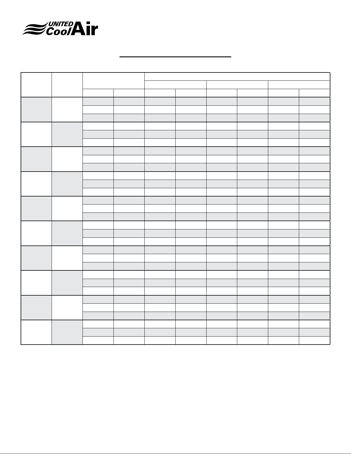
Air-Cooled Performance Data
Engineering Guide
Space Saver
Tons CFM
2 800
3 1200
4 1600
5 2000
6 2400
7 2800
8 3200
10 4000
12 4800
15 6000
Entering Air
Temp. Deg. F
DB WB Total Sensible Total Sensible Total Sensible
80 67 26673 19212 24209 18202 21648 17112
75 62.5 24699 18849 22297 17740 19938 16767
72 60 23671 18522 21358 17495 19006 16397
80 67 38032 27288 34827 25775 31124 24252
75 62.5 35344 26919 32388 25698 28911 23918
72 60 33918 26483 31040 25221 27755 23565
80 67 54796 39116 49682 37050 44182 34861
75 62.5 51031 38799 46100 36414 41042 34402
72 60 48935 38176 44228 35861 39243 33510
80 67 67072 47699 60866 45072 54155 42098
75 62.5 62416 47335 56603 44683 50338 41648
72 60 59864 46559 54244 43866 48124 40494
80 67 83311 59604 75718 56411 67232 52500
75 62.5 77265 58552 70188 55281 62533 51832
72 60 74107 57593 67293 54292 60003 50905
80 67 96049 67984 87698 64745 78680 61204
75 62.5 89517 67290 81499 63581 72990 59823
72 60 86013 66294 78367 62839 69689 57848
80 67 106064 79750 96116 74952 85300 70078
75 62.5 98654 78584 89500 74336 79448 69336
72 60 94690 77124 85814 72812 76182 67848
80 67 134540 100038 122182 95014 108698 88024
75 62.5 124794 98148 113204 92612 100954 86352
72 60 119684 96342 108508 90688 96740 84536
80 67 162296 121768 147800 115610 131990 109170
75 62.5 151268 119986 137988 114302 123102 107054
72 60 145352 117848 132490 112070 118156 104624
80 67 202032 151740 184456 144280 164616 134808
75 62.5 188650 149744 172390 142148 154412 133380
72 60 181170 146452 165708 139516 148528 130790
75 95 115
Air Over Condenser
Subject to change without notice. 20.3-TD (1018)
5
Page 6
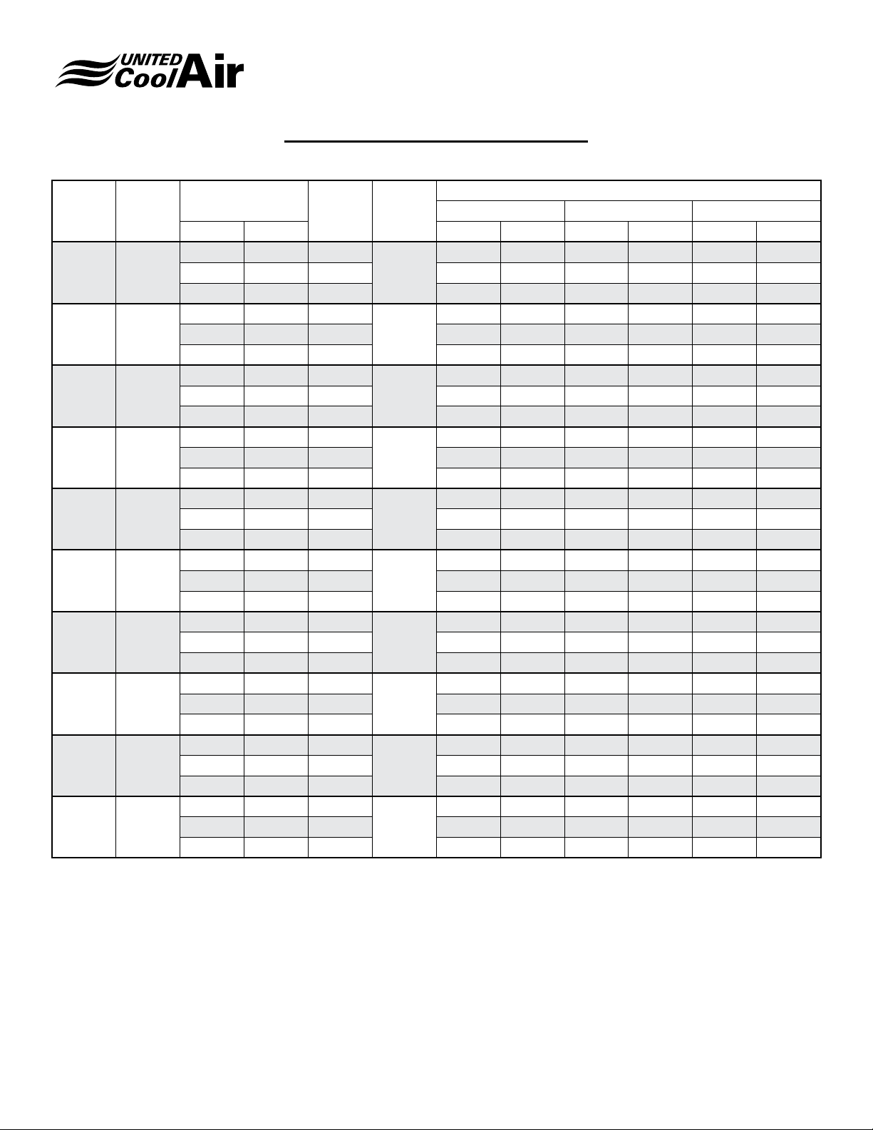
Water Cooled Performance Data
Engineering Guide
Space Saver
Tons CFM
2 800
3 1200
4 1600
5 2000
6 2400
7 2800
8 3200
10 4000
12 4800
15 6000
Entering Air Temp.
Deg. F
DB WB Total Sensible Total Sensible Total Sensible
80 67 13
75 62.5 13.1 25615 19286 24991 18994 24355 18697
72 60 13.1 24499 18929 23889 18633 23274 18309
80 67 9.1
75 62.5 9.1 36844 27655 35983 27254 35043 26986
72 60 9.1 35263 27164 34426 26760 33504 26493
80 67 13.2
75 62.5 13.2 51761 39312 50557 38608 49215 38178
72 60 13.2 49618 38488 48399 37917 47156 37341
80 67 9.2
75 62.5 9.2 63366 48003 61861 47292 60318 46585
72 60 9.2 60517 47448 59044 46757 57701 45709
80 67 15.2
75 62.5 15.2 79235 59739 77438 58918 75600 58079
72 60 15.2 75998 58509 74176 57861 72403 57024
80 67 15.7
75 62.5 15.7 92201 68573 90138 67596 88037 66605
72 60 15.7 88287 67912 86308 66895 84263 65911
80 67 13.2
75 62.5 13.2 101956 80140 99496 79018 96972 77780
72 60 13.2 97658 78516 95260 77276 92886 76096
80 67 9.2
75 62.5 9.2 125632 98616 122692 97156 119502 96000
72 60 9.2 120218 96770 117330 95226 114430 93808
80 67 15.2
75 62.5 15.2 157156 123686 153574 122142 150026 120436
72 60 15.2 150568 121388 147202 119768 143784 118048
80 67 17.7
75 62.5 17.8 196080 153766 191848 151818 187518 149510
72 60 17.8 188162 150092 184162 148060 179868 146506
PD
ft. H2O
GPM
27713 19584 27056 19302 26387 19018
6
39724 28244 38869 27694 37866 27490
9
55947 39694 54573 39175 53185 38679
12
68620 48299 66912 47853 65276 47142
15
85479 60593 83552 59784 81588 58934
18
99198 69351 96893 68681 94777 67458
24
110146 81228 107532 80120 104868 79002
24
135658 100550 132426 99246 129158 97916
30
169536 125444 165764 123872 161914 122246
36
211208 156098 206646 154154 201954 152134
45
Entering Water Temperature (10 Deg. Rise)
80 85 90
Subject to change without notice. 20.3-TD (1018)
6
Page 7
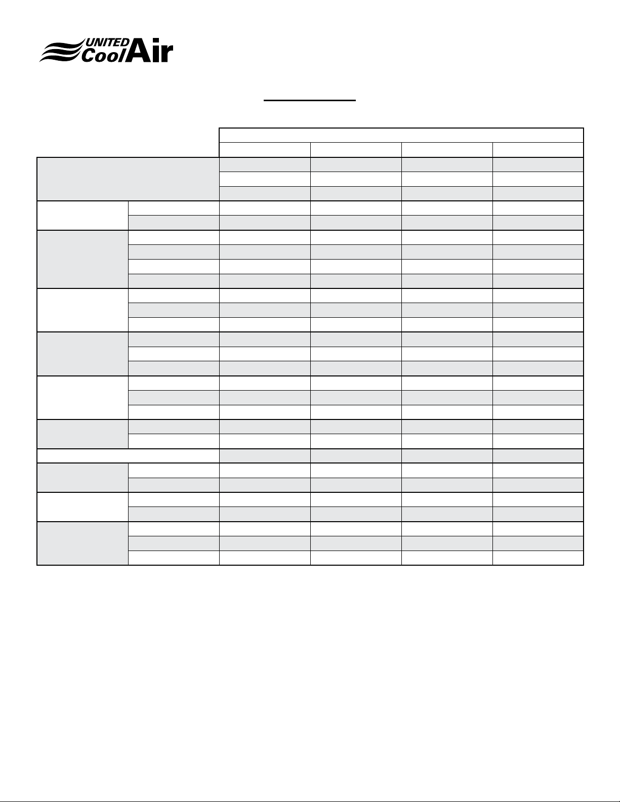
Engineering Guide
Space Saver
Physical Data
Tons
2 3 4 5
208/230-1-60 208/230-1-60 208/230-1-60 208/230-1-60
Voltage (e)
Supply Air (a)
CFM 800 1200 1600 2000
ESP 0.3” 0.3” 0.3” 0.3”
Size GT9 GT9 GT10 GT10
Evap. Blower
Qty 1 1 1 1
Type Direct Drive (h) Direct Drive (h) Belt Drive Belt Drive
HP (Std) 1/2 3/4 3/4 1
Rows Deep 2 2 4 4
Evaporator Coil
FPI
Face Area 3.1 3.1 4.3 4.3
Size 16 x 25 16 x 25 20 x 20 20 x 20
Filter (f)
Qty 1 1 2 2
Type Pleated Throwaway Pleated Throwaway Pleated Throwaway Pleated Throwaway
GPM 6 9 12 15
Water Cooled Cond.
Pressure Drop (b) 7 6.4 8.8 10.2
Type Coaxial Coaxial Coaxial Coaxial
Water Regulating
Valve (d)
Size 1/2 3/4 3/4 1
Qty 1 1 1 1
Chilled Water Valve Size (g) 1/2 1/2 3/4 3/4
Compressor R410A
Charge R410A
(Lbs-Ozs) ( c)
Type Scroll Scroll Scroll Scroll
Qty 1 1 1 1
Air-Cooled
Water-Cooled
Air-Cooled
Approx. Weight
(Net Operating)
Water-Cooled
Chilled Water
208/230-3-60 208/230-3-60 208/230-3-60 208/230-3-60
460-3-60 460-3-60 460-3-60 460-3-60
(a) Air ow performance may require other than standard drive components dependent upon options.
(b) Does not include water regulating valve�
(c) Split units need additional refrigerant� Refer to Installation Manual� Inclusion of some refrigerant
circuit components may add additional charge
(d) Water regulating valves are optional items and are available in a variety of congurations and
pressure ratings�
(e) Units also available in 575-3-60� Contact factory for electrical details�
(f) Filters are an optional item. 2" lters will t inside cabinet and 4" lters must be external.
(g) Optional component� All sizes sweat connection type�
(h) Belt Drive available as an option�
Subject to change without notice. 20.3-TD (1018)
7
Page 8

Engineering Guide
Space Saver
Physical Data
Tons
6 7 8 10 12 15
208/230-1-60 208/230-1-60 208/230-1-60 - - - - - - - - -
Voltage (e)
Supply Air (a)
CFM 2400 2800 3200 4000 4800 6000
ESP 0.3” 0.3” 0.3” 0.3” 0.3” 0.3”
Size GT10 GT10 GT10-2 GT10-2 GT12-2 GT12-2
Evap. Blower
Qty 1 1 2 2 2 2
Type Belt Drive Belt Drive Belt Drive Belt Drive Belt Drive Belt Drive
HP (Std) 1-1/2 2 1-1/2 2 2 3
Rows Deep 4 4 4 4 4 4
Evaporator Coil
FPI
Face Area 6.3 6.3 9 9 12.5 12.5
Size 20 X 20 25 x 20 25 x 20 25 x 25 I 25 x 20 25 X 25 I 25 X 20
Filter (f)
Qty 2 3 3 2 / 1 2 / 1
Type
GPM 18 21 24 30 36 45
Water Cooled Cond.
Pressure Drop (b) 8.8 14 8.8 10.2 8.8 14
Type Coaxial Coaxial Coaxial Coaxial Coaxial Coaxial
Water Regulating
Valve (d)
Size 1-1/4 1-1/2 3/4 1 1-1/4 1-1/4
Qty 1 1 2 2 2 2
Chilled Water Valve Size (g) 1 1 1 1 1-1/4 1-1/4
Compressor
Charge R-410A
(Lbs-Ozs) ( c)
Type Scroll Scroll Scroll Scroll Scroll Scroll
Qty 1 1 2 2 2 2
Air-Cooled
Water-Cooled
Air-Cooled
Approx. Weight
(Net Operating)
Water-Cooled
Chilled Water
208/230-3-60 208/230-3-60 208/230-3-60 208/230-3-60 208/230-3-60 208/230-3-60
460-3-60 460-3-60 460-3-60 460-3-60 460-3-60 460-3-60
Pleated
Throwaway
Pleated
Throwaway
Pleated
Throwaway
Pleated
Throwaway
Pleated
Throwaway
Pleated
Throwaway
(a) Air ow performance may require other than standard drive components dependent upon options.
(b) Does not include water regulating valve�
(c) Split units need additional refrigerant� Refer to Installation Manual� Inclusion of some refrigerant
circuit components may add additional charge�
(d) Water regulating valves are optional items and are available in a variety of congurations and
pressure ratings�
(e) Units also available in 575-3-60� Contact factory for electrical details�
(f) Filters are an optional item. 2" lters will t inside cabinet and 4" lters must be external.
(g) Optional component� All sizes sweat connection type�
(h) Belt Drive available as an option�
Subject to change without notice. 20.3-TD (1018)
8
Page 9

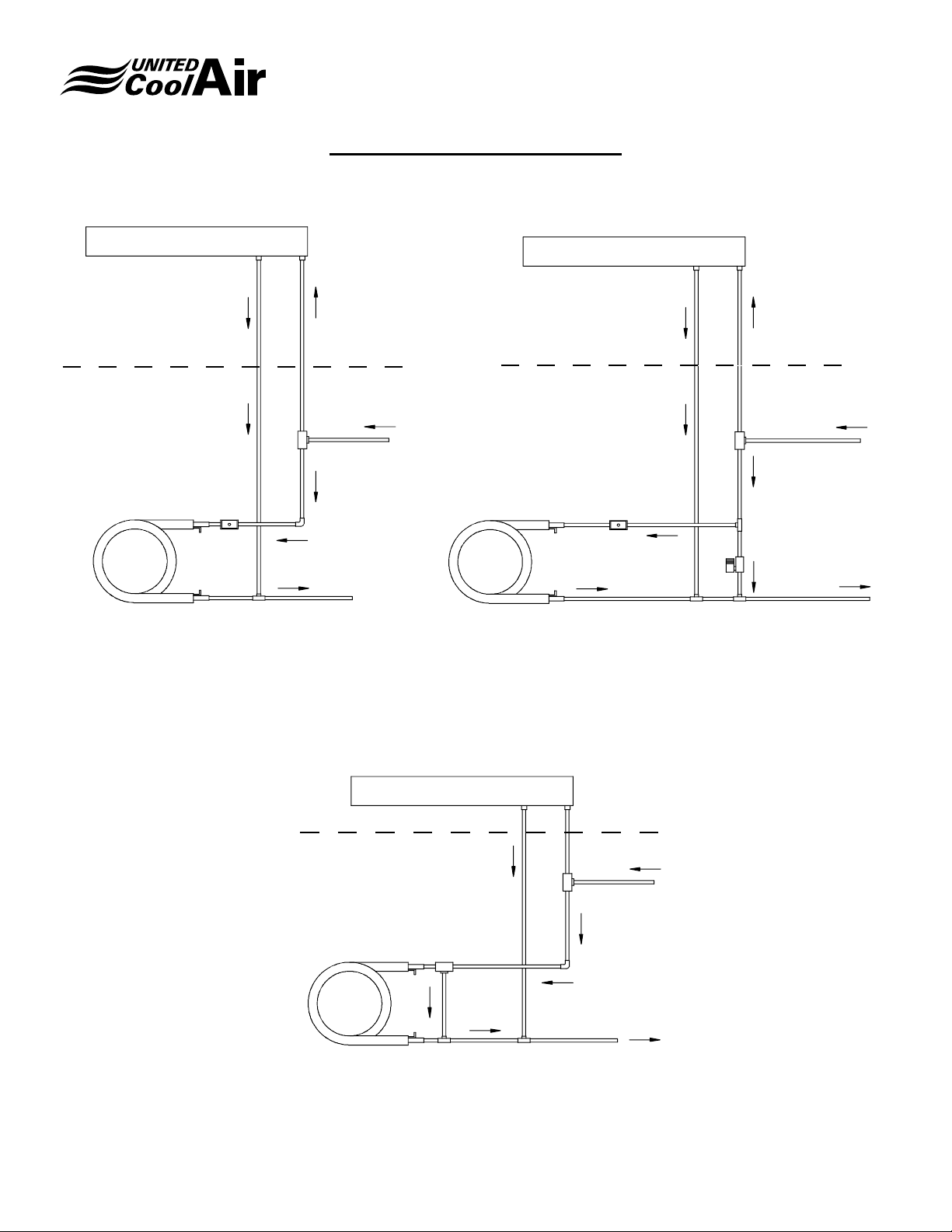
Water Piping Congurations
CONDENSING
COIL
CONDENSING
COIL
WATER
OUT
2-WAY
VALVE
WATE R
IN
TEE
TEE
N�O� SOLENOID
VALVE
2-WAY
VALVE
WATER
OUT
WATER
IN
CONDENSING
COIL
2-WAY SINGLE CIRCUIT
3-WAY SINGLE CIRCUIT
CONDENSING
COIL
2-WAY SINGLE CIRCUIT
CONDENSING
COIL
WATER
OUT
2-WAY
VALVE
WATE R
IN
WITH BYPASS
CONDENSING
COIL
2-WAY
VALVE
N�O� SOLENOID
VALVE
CONDENSING
COIL
WATER
OUT
2-WAY
VALVE
WATER
IN
CONDENSING
COIL
CONDENSING
COIL
TEE
TEE
TEE
TEE
TEE
TEE
N�O� SOLENOID
VALVE
3-WAY SINGLE CIRCUIT
CONDENSING
COIL
WATER
OUT
3-WAY
VALVE
WATER
IN
TEE
2-WAY SINGLE CIRCUIT
CONDENSING
COIL
WATER
OUT
2-WAY
VALVE
WATE R
IN
WITH BYPASS
CONDENSING
COIL
CONDENSING
COIL
TEE
WATER
OUT
WATER
IN
3-WAY
VALVE
2-WAY
VALVE
TEE
TEE
TEE
TEE
N�O� SOLENOID
VALVE
OPTIONAL GLOBE VALVE
CONDENSING
COIL
WATER
OUT
3-WAY
VALVE
WATER
IN
TEE
3-WAY SINGLE CIRCUIT
CONDENSING
COIL
WATER
OUT
3-WAY
VALVE
WATER
IN
TEE
Engineering Guide
Space Saver
2-Way Single Circuit
CONDENSING
COIL
3-Way Single Circuit
CONDENSING
COIL
3-WAY
VALVE
TEE
2-WAY
VALVE
WATER
IN
WATER
OUT
WATER
IN
WATER
OUT
CONDENSING
COIL
CONDENSING
COIL
CONDENSING
COIL
2-Way Single Circuit with Bypass
2-WAY
VALVE
N�O� SOLENOID
VALVE
2-Way Dual Circuit with Bypass
TEE
2-WAY
VALVE
2-WAY
VALVE
N�O� SOLENOID
VALVE
TEE
TEE
TEE
TEE
TEE
WATE R
IN
WATER
OUT
WATER
IN
WATER
OUT
3-Way Dual Circuit
CONDENSING
COIL
CONDENSING
COIL
Subject to change without notice. 20.3-TD (1018)
2-Way Dual Circuit
TEE
2-WAY
VALVE
2-WAY
VALVE
TEE
WATER
IN
WATER
OUT
3-WAY
VALVE
CONDENSING
COIL
TEE
CONDENSING
COIL
2-WAY
VALVE
9
OPTIONAL GLOBE VALVE
TEE
TEE
WATER
WATER
IN
OUT
Page 10
CONDENSING
COIL
3-WAY
VALVE
TEE
TEE
WATER
IN
3-WA Y
VALVE
WATE R
OUT
EVAPORATOR SECTION EVAPORATOR SECTION
EVAPORATOR SECTION EVAPORATOR SECTION
WATER SIDE ECONOMIZER
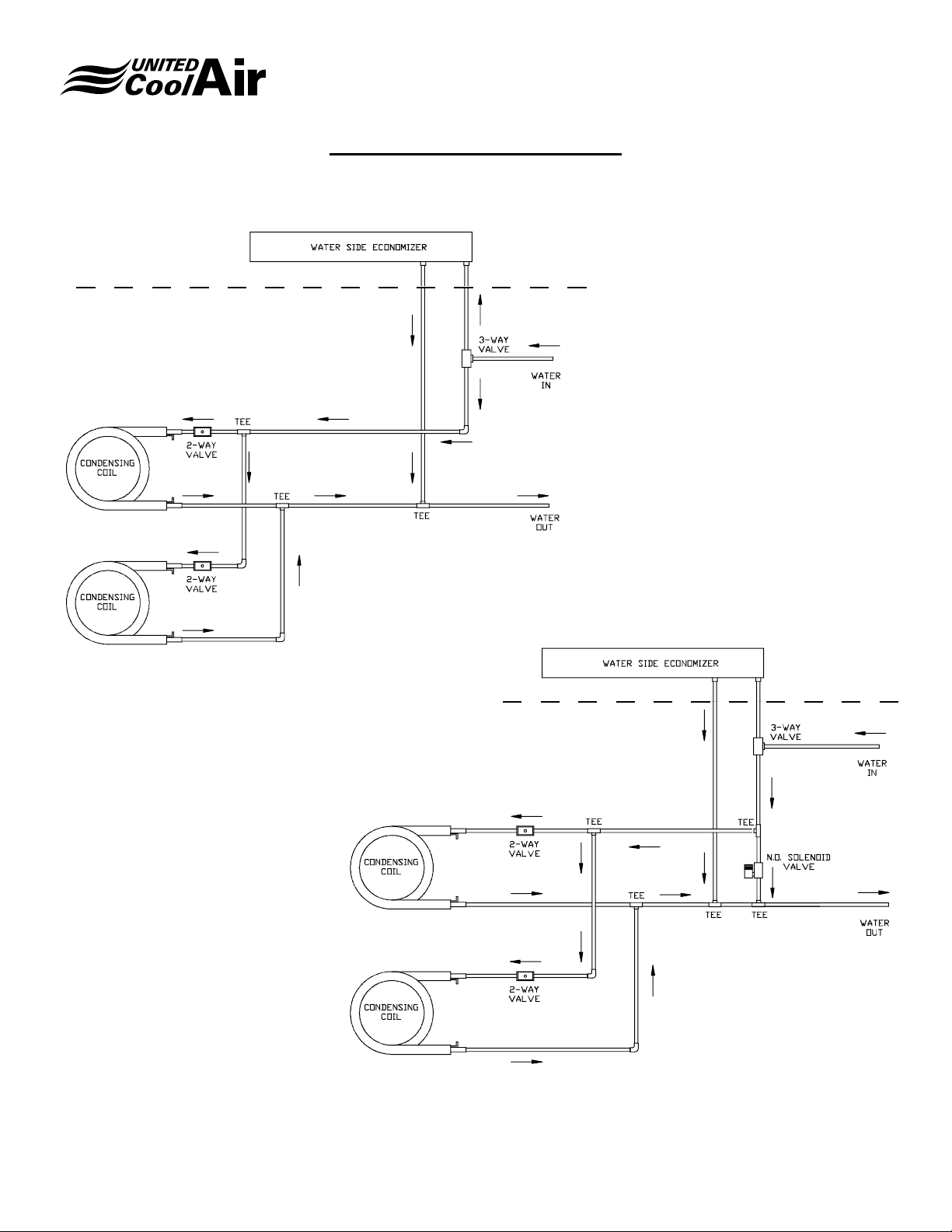
Water Piping Congurations
3-WAY SINGLE CIRCUIT
CONDENSING
COIL
2-WAY SINGLE CIRCUIT
CONDENSING
COIL
2-WAY
VALVE
N�O� SOLEN OID
VALVE
EVAPORATOR SECTION
WATER
OUT
WATER
IN
3-WAY
VALVE
TEE TEE
TEE
EVAPORATOR SECTION EVAPORATOR SECTION
WATER SIDE ECONOMIZER WATER SIDE ECONOMIZER WATER SIDE ECONOMIZER
TEE
EVAPORATOR SECTION
EVAPORATOR SECTION EVAPORATOR SECTION
WATER SIDE ECONOMIZER WATER SIDE ECONOMIZER
Engineering Guide
Space Saver
Evaporator Section
WATER SIDE ECONOMIZER
CONDENSING
COIL
2-Way Single Circuit with
Water-Side Economizer
2-WAY
VALVE
TEE
3-WAY
VALVE
WATE R
IN
WATER
OUT
CONDENSING
COIL
Evaporator Section
WATER SIDE ECONOMIZER
3-WAY
VALVE
TEE
2-WAY
VALVE
TEE
N�O� SOLEN OID
TEE
VALVE
2-Way Single Circuit with Bypass
WATER
IN
WATER
OUT
and Water-Side Economizer
Condenser Section
Condenser Section
Evaporator Section
WATER SIDE ECONOMIZER
3-WA Y
VALVE
WATER
IN
3-WAY
VALVE
WATE R
OUT
CONDENSING
COIL
with Water-Side Economizer
Subject to change without notice. 20.3-TD (1018)
TEE
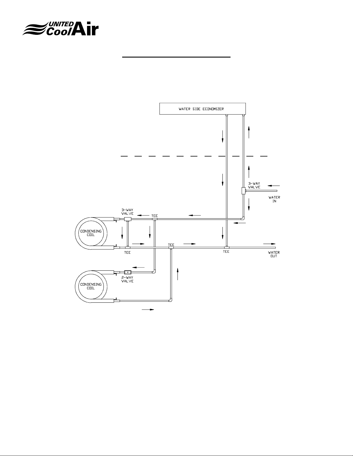
3-Way Single Circuit
Condenser Section
10
TEE
Page 11
Water Piping Congurations
Evaporator Section
Engineering Guide
Space Saver
2-Way Dual Circuit
with Water-Side Economizer
Condenser Section
Evaporator Section
2-Way Dual Circuit
with ByPass & Water-Side Economizer
Condenser Section
Subject to change without notice. 20.3-TD (1018)
11
Page 12
Water Piping Congurations
Evaporator Section
Engineering Guide
Space Saver
3-Way Dual Circuit
with Water-Side Economizer
Condenser Section
Subject to change without notice. 20.3-TD (1018)
12
Page 13

VSCW2G* Valve Size: 1/2"
Engineering Guide
Space Saver
Chilled Water Coil Performance
EWT GPM PD Ft H20 CFM
880 18,170 14,920 17,310 14,530 16,530 14,230 15,920 13,880
48
45
42
5.25 15.35
3.5 7
1.75 1.84
5.25 15.35
3.5 7
1.75 1.84
5.25 15.35
3.5 7
1.75 1.84
800 17,890 14,490 17,040 14,110 16,270 13,820 15,670 13,480
720 17,630 14,050 16,800 13,680 16,040 13.400 15,450 13,070
880 16,310 13.400 15,540 13,050 14,840 12,780 14,290 12.4,0
800 16,060 13,010 15,300 12,670 14,610 12,410 14,070 12,110
720 15,830 12,610 15,080 12,280 14.400 12,030 13,870 11,740
880 12,510 10,270 11,920 10,010 11,380 9,800 10,970 9,560
800 12,320 9,980 11,740 9,720 11,210 9,520 10,800 9,290
720 12,140 9,680 11,570 9,420 11,050 9,230 10,640 9,010
880 20,180 16,580 19,230 16,150 18,350 15,820 17,680 15,430
800 19,870 16,100 18,930 15,680 18,070 15,360 17,410 14,990
720 19,590 15,610 18,660 15,200 17,810 14,890 17,160 14,540
880 18,130 14,890 17,270 14,500 16,480 14,200 15,890 13,860
800 17,850 14,460 17,000 14,080 16,230 13,790 15,640 13,460
720 17,600 14,020 16,760 13,650 16,000 13,370 15,420 13,050
880 13,910 11,420 13,250 11,120 12,650 10,890 12,190 10,620
800 13,700 11,090 13,050 10,800 12,460 10,580 12,000 10,320
720 13,500 10,750 12,860 10,470 12,280 10,260 11,830 10,010
880 22,210 18,230 21,160 17,750 20,200 17,390 19,460 16,970
800 21,870 17,700 20,830 17,240 19,890 16,890 19,160 16,480
720 21,560 17,160 20,530 16,720 19,610 16,380 18,890 15,980
880 19,940 16,360 18,990 15,940 18,130 15,620 17,470 15,230
800 19,630 15,890 18,700 15,480 17,850 15,170 17,200 14,790
720 19,350 15,410 18,430 15,010 17,600 14,710 16,950 14,340
880 15,300 12,560 14,570 12,230 13,910 11,980 13,410 11,690
800 15,060 12,200 14,350 11,880 13,700 11,640 13,200 11,350
720 14,840 11,830 14,140 11,520 13,500 11,290 13,010 11,000
86 / 72 80 / 67 75 / 62.5 72 / 60
Total Sensible Total Sensible Total Sensible Total Sensible
Notes:
(1) Performance based on water as the chilled uid.
(2) Pressure drop is for the coil only and does not Include a valve�
(3) Unit shipped with coil stubbed through the cabinet and capped�
(4) Pressure drops over 10 Ft. H20 are considered excessive.
Contact the factory for a special coil selection to meet your specic parameters.
Subject to change without notice. 20.3-TD (1018)
13
Page 14
VSCW3G* Valve Size: 1/2"
Engineering Guide
Space Saver
Chilled Water Coil Performance
EWT GPM PD Ft H20 CFM
1320 23,300 19,890 22,190 19,380 21,190 18,990 20,420 18,520
48
45
42
6.75 24.12
4.5 11
2.25 2.89
6.75 24.12
4.5 11
2.25 2.89
6.75 24.12
4.5 11
2.25 2.89
1200 22,940 19,320 21,850 18,820 20,860 18,440 20,100 17,990
1080 22,610 18,740 21, 540 18,250 20,560 17,880 19,810 17,450
1320 20,920 17,870 19,930 17,400 19,020 17,050 18,330 16,630
1200 20,600 17,350 19,620 16,900 18,730 16,560 18,050 16,150
1080 20,310 16,820 19,340 16,390 18,460 16,060 17,790 15,660
1320 16,060 13,710 15,300 13,350 14,610 13,090 14,070 12,760
1200 15,810 13,320 15,060 12,970 14,380 12,710 13,850 12,390
1080 15,580 12,920 14,840 12,580 14,170 12,320 13,650 12,010
1320 25,890 22,120 24,660 21,540 23,550 21,110 22,680 20,580
1200 25,490 21,480 24,280 20,920 23,180 20,500 22,330 19,990
1080 25,130 20,830 23,940 20,290 22,850 19,880 22,010 19,390
1320 23, 250 19,850 22,140 19,340 21,140 18,950 20,370 18,480
1200 22,890 19,280 21,800 18,780 20,810 18,400 20,050 17,950
1080 22,560 18,700 21,490 18,210 20,510 17,840 19,760 17,410
1320 17,840 15,230 16,990 14,840 16,220 14,540 15,630 14,180
1200 17,560 14,790 16,730 14,410 15,970 14,120 15,390 13,770
1080 17,310 14,340 16,490 13,970 15,740 13,690 15,170 13,350
1320 28,480 24, 320 27,130 23,690 25,900 23, 210 24, 960 22,630
1200 28,040 23,620 26,710 23,000 25,500 22,540 24,570 21,980
1080 27,640 22,910 26,330 22,310 25,140 21,860 24,220 21,320
1320 25,570 21,830 24,360 21,260 23,260 20,830 22,410 20,330
1200 25,170 21,200 23,980 20,650 22,900 20,230 22,060 19,740
1080 24,810 20,560 23,640 20,030 22,570 19,620 21,750 19,140
1320 19,620 16,750 18,690 16,320 17,850 15,990 17,190 15,600
1200 19,320 16,270 18,400 15,850 17,570 15,530 16,920 15,150
1080 19,040 15,780 18,140 15,370 17,320 15,060 16,680 14,690
86 / 72 80 / 67 75 / 62.5 72 / 60
Total Sensible Total Sensible Total Sensible Total Sensible
Notes:
(1) Performance based on water as the chilled uid.
(2) Pressure drop is for the coil only and does not Include a valve�
(3) Unit shipped with coil stubbed through the cabinet and capped�
(4) Pressure drops over 10 Ft. H20 are considered excessive.
Contact the factory for a special coil selection to meet your specic parameters.
Subject to change without notice. 20.3-TD (1018)
14
Page 15

VSCW4G* Valve Size: 3/4"
Engineering Guide
Space Saver
Chilled Water Coil Performance
EWT GPM PD Ft H20 CFM
1760 46,300 37,010 44,100 36,050 42,110 35,320 40,560 34,460
48
45
42
10.5 15.35
7 7
3.5 1.84
10.5 15.35
7 7
3.5 1.84
10.5 15.35
7 7
3.5 1.84
1600 45,580 35,940 43,410 35,000 41,450 34,300 39,930 33,460
1440 44,940 34,860 42,800 33,950 40,860 33,270 39,370 32,450
1760 41,560 33,220 39,590 32,360 37,800 31,710 36,420 30,930
1600 40,910 32,260 38,970 31,420 37,210 30,790 35,850 30,030
1440 40,330 31,290 38,420 30,470 36,680 29,860 35,340 29,120
1760 31,900 25,510 30,380 24,840 29,010 24,330 27,950 23,740
1600 31,400 24,770 29,910 24,120 28,560 23,630 27,510 23,050
1440 30,960 24,020 29,490 23,390 28,160 22,920 27,120 22,350
1760 51,450 41,140 49,000 40,060 46,780 39,260 45,070 38,290
1600 50,640 39,950 48,230 38,900 46,050 38,120 44,370 37,180
1440 49,930 38,750 47,550 37,730 45,400 36,970 43,740 36,060
1760 46,180 36,930 43,990 35,960 42,010 35,240 40,460 34,380
1600 45,460 35,860 43,300 34,920 41,350 34,220 39,830 33,380
1440 44,820 34,780 42,690 33,870 40,770 33,190 39,270 32,370
1760 35,450 28,340 33,770 27,600 32,240 27,040 31,060 26,380
1600 34,900 27,520 33,240 26,800 31,740 26,260 30,580 25,620
1440 34,410 26,690 32,770 25,990 31,290 25,470 30,150 24,850
1760 56,600 45,240 53,900 44,060 51,480 43,170 49,590 42,110
1600 55,710 43,930 53,060 42,780 50,670 41,920 48,810 40,890
1440 54,930 42,610 52,310 41,490 49,960 40,660 48,120 39,660
1760 50,810 40,620 48,390 39,560 46,200 38,760 44,510 37,810
1600 50,010 39,440 47,630 38,410 45,480 37,640 43,810 36,710
1440 49,300 38,250 46,960 37,250 44,840 36,510 43,190 35,600
1760 38,990 31,170 37,140 30,360 35,460 29,750 34,160 29,020
1600 38,380 30,270 36,560 29,480 34,910 28,890 33,630 28,180
1440 37,840 29,360 36,040 28,590 34,420 28,020 33,150 27,330
86 / 72 80 / 67 75 / 62.5 72 / 60
Total Sensible Total Sensible Total Sensible Total Sensible
Notes:
(1) Performance based on water as the chilled uid.
(2) Pressure drop is for the coil only and does not Include a valve�
(3) Unit shipped with coil stubbed through the cabinet and capped�
(4) Pressure drops over 10 Ft. H20 are considered excessive.
Contact the factory for a special coil selection to meet your specic parameters.
Subject to change without notice. 20.3-TD (0917)
15
Page 16

VSCW5G* Valve Size: 3/4"
Engineering Guide
Space Saver
Chilled Water Coil Performance
EWT GPM PD Ft H20 CFM
2200 56,140 45,020 53,470 43,840 51,060 42,960 49,180 41,910
48
45
42
13.5 21.93
9 10
4.5 2.63
13.5 21.93
9 10
4.5 2.63
13.5 21.93
9 10
4.5 2.63
2000 55,260 43,710 52,630 42,570 50,260 41,710 48,410 40,690
1800 54,480 42,390 51,890 41,290 49,550 40,450 47,730 39,460
2200 50,400 40,420 48,000 39,360 45,840 38,570 44,160 37,620
2000 49,610 39,250 47,250 38,220 45,120 37,450 43,470 36,530
1800 48,910 38,070 46,580 37,070 44,480 36,320 42,860 35,430
2200 38,680 31,030 36,850 30,220 35,180 29,610 33,890 28,880
2000 38,080 30,130 36,270 29,340 34,630 28,750 33,360 28,040
1800 37,540 29,220 35,760 28,450 34,140 27,880 32,890 27,190
2200 62,380 50,030 59,410 48,720 56,730 47,750 54,660 46,570
2000 61,400 48,580 58,480 47,310 55,840 46,360 53,800 45,220
1800 60,540 47,120 57,660 45,890 55,050 44,960 53,040 43,860
2200 56,000 44,910 53,340 43,740 50,930 42,860 49,070 41,810
2000 55,120 43,610 52,500 42,470 50,130 41,620 48,300 40,600
1800 54,340 42,300 51,760 41,190 49,420 40,370 47,620 39,380
2200 42,980 34,480 40,940 33,570 39,090 32,890 37,660 32,090
2000 42,310 33,480 40,300 32,600 38,480 31,940 37,070 31,160
1800 41,710 32,470 39,730 31,620 37,940 30,980 36,550 30,220
2200 68,620 55,030 65,350 53,590 62,410 52,500 60,120 51,230
2000 67,540 53,430 64,330 52,030 61,430 50,980 59,180 49,740
1800 66,590 51,820 63,420 50,460 60,560 49,450 58,350 48,240
2200 61,600 49,400 58,670 48,110 56,030 47,140 53,980 45,980
2000 60,630 47,970 57,750 46,710 55,150 45,770 53,130 44,650
1800 59,780 46,530 56,940 45,300 54,370 44,390 52,380 43,310
2200 47,280 37,910 45,030 36,920 43,000 36,180 41,430 35,290
2000 48,540 36,810 44,330 35,850 42,330 35,130 40,780 34,270
1800 45,880 35,700 43,700 34,770 41,730 34,070 40,200 33,240
86 / 72 80 / 67 75 / 62.5 72 / 60
Total Sensible Total Sensible Total Sensible Total Sensible
Notes:
(1) Performance based on water as the chilled uid.
(2) Pressure drop is for the coil only and does not Include a valve�
(3) Unit shipped with coil stubbed through the cabinet and capped�
(4) Pressure drops over 10 Ft. H20 are considered excessive.
Contact the factory for a special coil selection to meet your specic parameters.
Subject to change without notice. 20.3-TD (0917)
16
Page 17

VSCW6G* Valve Size: 1"
Engineering Guide
Space Saver
Chilled Water Coil Performance
EWT GPM PD Ft H20 CFM
2640 69,510 54,050 66,210 52,640 63,220 51,580 60,900 50,320
48
45
42
15 10.97
10 5
5 1.32
15 10.97
10 5
5 1.32
15 10.97
10 5
5 1.32
2400 68,420 52,480 65,170 51,110 62,230 50,080 59,950 48,860
2160 67,460 50,900 64,250 49,570 61,350 48,570 59,110 47,390
2640 62,400 48,520 59,430 47,250 56,750 46,300 54,680 45,170
2400 61,420 47,110 58,500 45,880 55,860 44,960 53,820 43,860
2160 60,560 45,690 57,680 44,500 55,070 43,610 53,060 42,540
2640 47,900 37,250 45,620 36,270 43,560 35,540 41,970 34,680
2400 47,150 36,170 44,910 35,220 42,880 34,510 41,310 33,670
2160 46,480 35,080 44,280 34,160 42,270 33,470 40,730 32,650
2640 77,240 60,060 73,560 58,490 70,250 57,310 67,670 55,910
2400 76,030 58,320 72,410 56,190 69,150 55,650 66,610 54,290
2160 74,960 56,570 71,390 55,080 68,180 53,980 65,670 52,660
2640 69,340 53,920 66,040 52,500 63,060 51,450 60,750 50,190
2400 68,250 52,350 65,000 50,980 62,070 49,960 59,800 48,730
2160 67,290 50,770 64,090 49,450 61,200 48,460 58,960 47,260
2640 53,220 41,380 50,690 40,300 48,410 39,490 46,630 38,520
2400 52,390 40,180 49,900 39,130 47,650 38,340 45,900 37,400
2160. 51,650 38,970 49,200 37,950 46,980 37,180 45,250 36,270
2640 84,960 66,060 80,920 64,330 77,270 63,040 74,440 61,500
2400 83,630 64,140 79,650 62,460 76,060 61,210 73,270 59,710
2160 82,450 62,210 78,530 60,580 74,990 59,370 72,240 57,910
2640 76,270 59,300 72,640 57,750 69,370 56,580 66,830 55,200
2400 75,070 57,580 71,500 56,070 68,280 54,940 65,780 53,600
2160 74,010 55,850 70,490 54,380 67,320 53,290 64,850 51,990
2640 58,550 45,520 55,760 44,330 53,240 43,430 51,290 42,370
2400 57,630 44,200 54,890 43,040 52,410 42,170 50,490 41,140
2160 56,820 42,870 54,120 41,740 51,670 40,900 49,780 39,900
86 / 72 80 / 67 75 / 62.5 72 / 60
Total Sensible Total Sensible Total Sensible Total Sensible
Notes:
(1) Performance based on water as the chilled uid.
(2) Pressure drop is for the coil only and does not Include a valve�
(3) Unit shipped with coil stubbed through the cabinet and capped�
(4) Pressure drops over 10 Ft. H20 are considered excessive.
Contact the factory for a special coil selection to meet your specic parameters.
Subject to change without notice. 20.3-TD (1018)
17
Page 18

VSCW7G* Valve Size: 1"
Engineering Guide
Space Saver
Chilled Water Coil Performance
EWT GPM PD Ft H20 CFM
3080 79,060 61,660 75,300 60,040 71,910 58,840 69,280 57,400
48
45
42
18 15.35
12 7
6 1.84
18 15.35
12 7
6 1.84
18 15.35
12 7
6 1.84
2800 77,820 59,870 74,120 58,300 70,780 57,130 68,190 55,730
2520 76,730 58,070 73,080 56,550 69,780 55,410 67,230 54,050
3080 70,970 55,360 67,600 53,910 64,550 52,820 62,180 51,530
2800 69,860 53,750 66,540 52,340 63,540 51,290 61,210 50,030
2520 68,880 52,130 65,600 50,760 62,650 49,750 60,350 48,520
3080 54,480 42,490 51,890 41,380 49,560 40,550 47,740 39,560
2800 53,630 41,260 51,080 40,180 48,780 39,370 46,990 38,410
2520 52,870 40,020 50,360 38,970 48,090 38,180 46,330 37,250
3080 87,860 68,520 83,680 66,730 79,910 65,390 76,990 63,780
2800 86,480 66,530 82,370 64,790 78,660 63,490 15,780 61,930
2520 85,260 64,530 81,210 62,840 77,550 61,580 74,710 60,070
3080 78,870 61,520 75,120 59,900 71,730 58,690 69,100 57,260
2800 77,630 59,730 73,940 58,160 70,610 56,990 68,020 55,600
2520 76,540 57,930 72,900 56,410 69,620 55,280 67,060 53,930
3080 60,540 47,220 57,660 45,980 55,060 45,060 53,040 43,960
2800 59,590 45,850 56,760 44,650 54,200 43,750 52,210 42,680
2520 58,750 44,470 55,960 43,310 53,440 42,430 51,470 41,390
3080 96,650 75,370 92,040 73,390 87:900 71,920 84,680 70,160
2800 95,130 73,180 90,600 71,260 86,520 69,830 83,350 68,120
2520 93,790 70,980 89,330 69,120 85,300 67,730 82,180 66,070
3080 86,750 67,660 82,630 65,880 78,910 64,570 76,010 62,980
2800 85,390 65,690 81,330 63,970 77,670 62,690 74,820 61,150
2520 84,190 63,710 80,190 62,050 76,580 60,800 73,770 59,310
3080 66,590 51,940 63,420 50,580 60,570 49,560 58,340 48,340
2800 65,550 50,430 62,430 49,110 59,620 48,120 57,430 46,940
2520 64,630 48,910 61,550 47,630 58,780 46,670 56,620 45,530
86 / 72 80 / 67 75 / 62.5 72 / 60
Total Sensible Total Sensible Total Sensible Total Sensible
Notes:
(1) Performance based on water as the chilled uid.
(2) Pressure drop is for the coil only and does not Include a valve�
(3) Unit shipped with coil stubbed through the cabinet and capped�
(4) Pressure drops over 10 Ft. H20 are considered excessive.
Contact the factory for a special coil selection to meet your specic parameters.
Subject to change without notice. 20.3-TD (0917)
18
Page 19

VSCW8G* Valve Size: 1"
Engineering Guide
Space Saver
Chilled Water Coil Performance
EWT GPM PD Ft H20 CFM
3520 95,390 75,290 90,850 73,310 86,750 71,840 83,570 70,080
48
45
42
22.5 15.35
15 7
7.5 1.84
22.5 15.35
15 7
7.5 1.84
22.5 15.35
15 7
7.5 1.84
3200 93,890 73,100 89,420 71,180 85,390 69,750 82,260 68,040
2880 92,570 70,900 88,160 69,040 84,190 67,650 81,100 65,990
3520 85,620 67,580 81,550 65,810 77,870 64,490 75,020 62,910
3200 84,280 65,620 80,270 63,900 76,650 62,620 73,840 61,080
2880 83,100 63,650 79,140 61,980 75,570 60,740 72,800 59,240
3520 65,730 51,880 62,600 50,520 59,780 49,500 57,590 48,290
3200 64,700 50,370 61,620 49,050 58,840 48,060 56,690 46,890
2880 63,790 48,850 60,750 47,570 58,010 46,610 55,890 45,480
3520 105,970 83,650 100,930 81,460 96,380 79,820 92,860 77,870
3200 104,310 81,220 99,350 79,090 94,870 77,500 91,400 75,610
2880 102,840 78,780 97,950 76,710 93,540 75,170 90,120 73, 340
3520 95,130 75,090 90,610 73,130 86,530 71,660 83,360 69,900
3200 93,640 72,910 89,190 71,000 85,170 69,580 82,050 67,870
2880 92,320 70,720 87,940 68,810 83,970 67,490 80,900 65,830
3520 73,040 57,640 69,560 56,130 66,420 55,010 63,990 53,660
3200 71,890 55,970 68,470 54,500 65,380 53,410 62,990 52,100
2880 70,880 54,290 67,510 52,860 64,460 51,800 62,100 50,530
3520 116,570 92,020 111,020 89,610 106,020 87,810 102,130 85,660
3200 114,740 89,340 109,280 87,000 104,360 85,260 100,530 83,170
2880 113,130 86,650 107,750 84,390 102,890 82,700 99,120 80,670
3520 104,640 82,600 99,660 80,440 95,170 78,820 91,690 76,890
3200 103,000 80,200 98,100 78,100 93,680 76,530 90,250 74,660
2880 101,550 77,790 96,720 75,150 92,360 14,230 88,980 72,420
3520 80,330 63,400 76,510 61,740 73,070 60,510 70,380 59,020
3200 79,070 61,560 75,310 59,950 71,920 58,750 69,280 57,310
2880 77,960 59,710 74,250 58,150 70,910 56,980 68,310 55,590
86 / 72 80 / 67 75 / 62.5 72 / 60
Total Sensible Total Sensible Total Sensible Total Sensible
Notes:
(1) Performance based on water as the chilled uid.
(2) Pressure drop is for the coil only and does not Include a valve�
(3) Unit shipped with coil stubbed through the cabinet and capped�
(4) Pressure drops over 10 Ft. H20 are considered excessive.
Contact the factory for a special coil selection to meet your specic parameters.
Subject to change without notice. 20.3-TD (1018)
19
Page 20

VSCW10G* Valve Size: 1"
Engineering Guide
Space Saver
Chilled Water Coil Performance
EWT GPM PD Ft H20 CFM
4400 112,090 89,920 106,760 87,570 101,950 85,800 98,210 83,700
48
45
42
27 19.7
18 9
9 2.37
27 19.7
18 9
9 2.37
27 19.7
18 9
9 2.37
4000 110,330 87,310 105,080 85,020 100,350 83,310 96,670 81,270
3600 108,780 84,690 103,600 82,460 98,940 80,810 95,310 78,830
4400 100,620 80,730 95,830 78,600 91,520 77,030 88,160 75,140
4000 99,040 78,380 94,330 76,320 90,080 74,790 86,780 12,960
3600 97,650 76,020 93,000 74,030 88,810 72,540 85,560 70,770
4400 77,240 61,970 73,560 60,340 70,250 59,130 67,670 57,690
4000 76,030 60,170 72,410 58,590 69,150 57,410 66,610 56,010
3600 74,960 58,360 71,390 56,830 68,180 55,680 65,670 54,320
4400 124,560 99,920 118,630 97,290 113,290 95,340 109,130 93,000
4000 122,600 97,010 116,770 94,460 111,510 92,570 107,420 90,300
3600 120,880 94,090 115,130 91,620 109,940 89,790 105,910 87,590
4400 111,820 89,690 106,490 87,340 101,700 85,590 97,970 83,490
4000 110,060 87,080 104,820 84,800 100,100 83,100 96,430 81,060
3600 108,510 84,460 103,350 82,250 98,690 80,600 95,070 78,620
4400 85,840 68,850 81,750 67,050 78,060 65,700 75,210 64,090
4000 84,490 66,850 80,470 65,100 76,840 63,790 74,030 62,230
3600 83,300 64,840 79,340 63,140 75,760 61,870 72,990 60,360
4400 137,010 109,910 130,490 107,020 124,620 104,880 120,050 102,300
4000 134,860 106,710 128,440 103,910 122,660 101,830 118,160 99,330
3600 132,970 103,500 126,640 100,790 120,940 98,770 116,500 96,350
4400 122,990 98,660 117,140 96,070 111,870 94,150 107,760 91,840
4000 121,060 95,790 115,300 93,280 110,110 91,410 106,070 89,170
3600 119,360 92,910 113,680 90,480 108,560 88,660 104,580 86,490
4400 94,410 75,740 89,920 73,750 85,870 72,270 82,720 70,500
4000 92,930 73,540 88,510 71,610 84,520 10,170 81,420 68,450
3600 91,620 71,330 87,270 69,460 83,330 68,060 80,280 66,390
86 / 72 80 / 67 75 / 62.5 72 / 60
Total Sensible Total Sensible Total Sensible Total Sensible
Notes:
(1) Performance based on water as the chilled uid.
(2) Pressure drop is for the coil only and does not Include a valve�
(3) Unit shipped with coil stubbed through the cabinet and capped�
(4) Pressure drops over 10 Ft. H20 are considered excessive.
Contact the factory for a special coil selection to meet your specic parameters.
Subject to change without notice. 20.3-TD (1018)
20
Page 21

VSCW12G* Valve Size: 1-1/4"
Engineering Guide
Space Saver
Chilled Water Coil Performance
EWT GPM PD Ft H20 CFM
5280 146,910 113,660 139,920 110,670 133,620 108,450 128,720 105,800
48
45
42
30 13.13
20 6
10 1.58
30 13.13
20 6
10 1.58
30 13.13
20 6
10 1.58
4800 144,600 110,350 137,720 107,450 131,520 105,300 126,700 102,720
4320 142,570 107,030 135,790 104,220 129,670 102,140 124,920 99,630
5280 131,880 102,030 125,600 99,350 119,940 97,360 115,540 94,970
4800 129,810 99,060 123,630 96,460 118,060 94,530 113,730 92,210
4320 127,990 96,080 121,890 93,560 116,400 91,690 112,130 89,440
5280 101,240 78,320 96,420 76,270 92,080 74,730 88,700 72,910
4800 99,650 76,040 94,910 74,050 90,630 72,560 87,310 70,790
4320 98,250 73,750 93,580 71,820 89,360 70,380 86,080 68,660
5280 163,250 126,290 155,470 122,980 148,470 120,520 143,030 117,560
4800 160,680 122,620 153,030 119,400 146,140 117,010 140,780 114,140
4320 158,430 118,940 150,880 115,810 144,090 113,490 138,800 110,710
5280 146,540 113,370 139,570 110,390 133,280 108,180 128,400 105,530
4800 144,240 110,070 137,375 107,180 131,190 105,030 126,380 102,460
4320 142,220 106,760 135,450 103,960 129,350 101,870 124,610 99,380
5280 112,500 87,030 107,140 84,740 102,320 83,040 98,570 81,000
4800 110,730 84,500 105,460 82,280 100,710 80,630 97,020 78,650
4320 109,170 81,960 103,980 79,810 99,300 78,210 95,660 76,290
5280 179,570 138,910 171,030 135,260 163,330 132,560 157,340 129,310
4800 176,750 134,870 168,340 131,330 160,760 128,700 154,870 125,550
4320 174,270 130,820 165,980 127,390 158,500 124,830 152,700 121,780
5280 161,190 124,700 153,520 121,420 146,610 118,990 141,240 116,080
4800 158,660 121,070 151,110 117,890 144,310 115,530 139,020 112,700
4320 156,430 117,430 148,990 114,350 142,280 112,060 137,070 109,310
5280 123,740 95,720 117,850 93,210 112,550 91,350 108,420 89,100
4800 121,800 92,940 116,000 90,500 110,780 88,690 106,720 86,510
4320 120,090 90,150 114,370 87,780 109,220 86,020 105,220 83,910
86 / 72 80 / 67 75 / 62.5 72 / 60
Total Sensible Total Sensible Total Sensible Total Sensible
Notes:
(1) Performance based on water as the chilled uid.
(2) Pressure drop is for the coil only and does not Include a valve�
(3) Unit shipped with coil stubbed through the cabinet and capped�
(4) Pressure drops over 10 Ft. H20 are considered excessive.
Contact the factory for a special coil selection to meet your specic parameters.
Subject to change without notice. 20.3-TD (1018)
21
Page 22

VSCW15G* Valve Size: 1-1/4"
Engineering Guide
Space Saver
Chilled Water Coil Performance
EWT GPM PD Ft H20 CFM
6600 173,920 136,150 165,640 132,580 158,190 129,920 152,380 126,740
48
45
42
37.5 19.7
25 9
12.5 2.37
37.5 19.7
25 9
12.5 2.37
37.5 19.7
25 9
12.5 2.37
6000 171,190 132,190 163,040 128,720 155,700 126,140 149,990 123,050
5400 168,790 128,220 160,750 124,850 153,520 122,350 147,890 119,350
6600 156,120 122,210 148,700 119,010 142,000 116,620 136,800 113,770
6000 153,670 118,660 146,360 115,550 139,770 113,230 134,650 110,460
5400 151,510 115,100 144,310 112,080 137,810 109,830 132,760 107,140
6600 119,850 93,820 114,150 91,360 109,010 89,520 105,020 87,330
6000 117,970 91,090 112,360 88,700 107,300 86,920 103,370 84,190
5400 116,310 88,350 110,780 86,030 105,790 84,310 101,920 82,240
6600 193,260 151,280 184,060 147,310 175,770 144,350 169,330 140,820
6000 190,220 146,880 181,170 143,020 173,010 140,150 166,670 136,720
5400 187,550 142,470 178,630 138,720 170,580 135,940 164,330 132,610
6600 173,490 135,800 165,230 132,240 157,790 129,590 152,000 126,420
6000 170,760 131,850 162,630 128,390 155,310 125,820 149,610 122,740
5400 168,360 127,890 160,350 124,530 153,130 122,040 147,510 119,050
6600 133,180 104,250 126,840 101,510 121,130 99,470 116,690 97,040
6000 131,090 101,220 124,850 98,560 119,230 96,580 114,860 94,220
5400 129,250 98,180 123,100 95,600 117,560 93,680 113,250 91,390
6600 212,580 166,400 202,460 162,030 193,350 158,790 186,260 154,900
6000 209, 240 161,560 199,280 157,320 190,310 154,170 183,330 150,390
5400 206,310 156,710 196,490 152,600 187,640 149,540 180,760 145,870
6600 190,830 149,380 181,750 145,450 173,560 142,540 167,200 139,050
6000 187,830 145,030 178,890 141,220 170,830 138,390 164,570 135,000
5400 185,200 140,670 176,380 136,980 168,430 134,230 162,260 130,950
6600 146,490 114,660 139,520 111,660 133,240 109,420 128,360 106,130
6000 144,190 111,330 137,330 108,410 131,150 106,240 126,340 103,630
5400 142,170 107,990 135,400 105,150 129,310 103,050 124,570 100,520
86 / 72 80 / 67 75 / 62.5 72 / 60
Total Sensible Total Sensible Total Sensible Total Sensible
Notes:
(1) Performance based on water as the chilled uid.
(2) Pressure drop is for the coil only and does not Include a valve�
(3) Unit shipped with coil stubbed through the cabinet and capped�
(4) Pressure drops over 10 Ft. H20 are considered excessive.
Contact the factory for a special coil selection to meet your specic parameters.
Subject to change without notice. 20.3-TD (1018)
22
Page 23

Hot Water Coils
65 Deg. F Entering Air 180 Deg. F Entering Water
TONS Valve Size (a) CFM GPM PD H. (b) BTUH
2 1/2" 800 3 5 27,920
3 1/2" 1200 4 8.8 35,990
4 1/2" 1600 5 4.6 53,200
5 3/4" 2000 6 6.4 61,430
6 3/4" 2400 8 6 79.480
7 1" 2800 10 9 88,960
8 1" 3200 12 7.3 129,770
10 1" 4000 14 9.7 148,900
12 1" 4800 16 6.9 179,710
15 1-1/4" 6000 18 8.6 204,630
Notes:
(a) Valves are an optional item�
(b) Does not include valve�
Engineering Guide
Space Saver
Hot Water Correction Factors
Entering Air
Deg. F
50 0.779 0.875 0.954 1.037 1.127 1.217
55 0.745 0.828 0.910 1.000 1.085 1.170
60 0.702 0.779 0.875 0.954 1.037 1.130
65 0.666 0.745 0.828 0.910 1.000 1.080
70 0.616 0.702 0.779 0.875 0.954 1.033
140 150 160 170 180 200
Entering Water Temperature
Steam Coils
65 Deg. F Entering Air 1PSIG Steam Pressure
TONS CFM BTUH
2 800 38,400 39.7
3 1200 47,200 48.8
4 1600 70,340 72.7
5 2000 78,660 81.3
6 2400 108,070 111.7
7 2800 128,930 133.2
8 3200 149,790 154.8
10 4000 167,835 173.4
12 4800 196,550 203.1
15 6000 219,310 226.6
Condensate
Lb / Hr
Subject to change without notice. 20.3-TD (1018)
23
Page 24

Steam Heating Correction Factors
Engineering Guide
Space Saver
Hot Water Coils
Entering Air
Deg. F
40 1.165 1.180 1.230 1.290
60 1.035 1.065 1.115 1.175
65 1.000 1.023 1.073 1.143
70 0.965 0.980 1.030 1.110
1 2 5 10
Steam Pressure
Control Wire Sizes
Wire Size1 AWG. Gauge
22 20 19 18 16
40 120 150 190 305
Maximum Wire Length2 Feet
(1) Solid, Class 11 copper wire
(2) Based on a voltage drop of 1�2 volts per wire�
(3) Total wire length is from unit to room thermostat, and back to unit
Application Data (a)
Voltage Variation
Cooling (b)
(Air Over Evap.)
Water-Cooled
(a) Dependent upon specic application, some additional refrigerant circuit
considerations may be required�
(b) Not all combinations may be valid�
208/230 460
187/253 414/504
DB (min./max.) 65/110
WB (min./max.) 57/72
GPM/Ton (min./max.) 2.5/3.5
Leaving Water Temp. 60/115
(min./max.)
Minimum Service Access Requirements
Access panels are provided on the front of the unit�
Tons Front Side (a)
2 - 15 36" 24"
(a) Some options and unit arrangements may require side access
Subject to change without notice. 20.3-TD (1018)
24
Page 25

Correction factor for Variation in Airow
Engineering Guide
Space Saver
% of CFM
80 0.97 0.94
85 0.98 0.95
90 0.99 0.97
100 1.00 1.00
110 1.02 1.03
120 1.03 1.06
Corrects to Total for Entering Wet Bulb and also Sensible vs� Entering Dry Bulb / Wet Bulb
Total
WB
Cig
Cap.
57 0.860 1.010 1.038 1.066 1.094 1.122 1.150 1.150 1.150 1.150 1,150 1.150 1.150 1.150 1.150 1.150 1.150
58 0.880 0.968 0.999 1.030 1.060 1.091 1.122 1.132 1.142 1.153 1.163 1.173 1.173 1.173 1.173 1.173 1.173
69 0.905 0.925 0.959 0.993 1.026 1.060 1.094 1.114 1.134 1.155 1.175 1.195 1.195 1.195 1.195 1.195 1.195
60 0.920 0.882 0.919 0.956 0.992 1.029 1.066 1.096 1.121 1.157 1.188 1.218 1.218 1.218 1.218 1.218 1.218
61 0.935 0.840 0.880 0.920 0.960 1.000 1.040 1.080 1.120 1.160 1.200 1.240 1.240 1.240 1.240 1.240 1.240
62 0.950 0.797 0.838 0.878 0.919 0.959 1.000 1.041 1.081 1.122 1.162 1.203 1.215 1.227 1.239 1.251 1.263
63 0.960 0.754 0.795 0.836 0.878 0.919 0.960 1.001 1.042 1.084 1.125 1.166 1.190 1.214 1.238 1.262 1.286
64 0.970 0.710 0.752 0.794 0.836 0.878 0.920 0.962 1.004 1.046 1.088 1.130 1.166 1.202 1.238 1.274 1.310
65 0.980 0.663 0.706 0.749 0.791 0.834 0.877 0.919 0.961 1.003 1.045 1.087 1.125 1.163 1.201 1.239 1.277
66 0.990 0.616 0.660 0.703 0.747 0.790 0.834 0.876 0.918 0.960 1.002 1.044 1.084 1.124 1.164 1.204 1.244
67 1.000 0.570 0.614 0.658 0.702 0.746 0.790 0.832 0.874 0.916 0.958 1.000 1.042 1.084 1.126 1.168 1.210
68 1.010 0.523 0.567 0.612 0.656 0.701 0.745 0.787 0.829 0.871 0.913 0.955 0.997 1.039 1.081 1.123 1.165
69 1.020 0.476 0.521 0.566 0.610 0.655 0.700 0.742 0.784 0.826 0.868 0.910 0.952 0.994 1.036 1.078 1.120
70 1.030 0.474 0.519 0.565 0.610 0.655 0.697 0.739 0.781 0.823 0.865 0.907 0.949 0.991 1.033 1.075
71 1.040 0.473 0.519 0.564 0.610 0.652 0.694 0.736 0.778 0.820 0.862 0.904 0.946 0.988 1.030
72 1.050 0.473 0.519 0.565 0.607 0.649 0.691 0.733 0.775 0.817 0.859 0.901 0.943 0.985
73 1.060 0.474 0.520 0.562 0.604 0.646 0.688 0.730 0.772 0.814 0.856 0.898 0.940
74 1.070 0.468 0.511 0.554 0.596 0.639 0.682 0.726 0.770 0.814 0.858 0.902
76 1.080 0.460 0.503 0.547 0.507 0.634 0.677 0.720 0.764 0.807 0.850
76 1.090 0.453 0.497 0.542 0.586 0.626 0.666 0.706 0.746 0.786
77 1.100 0.448 0.493 0.538 0.580 0.622 0.664 0.706 0.748
78 1.110 0.444 0.490 0.534 0.578 0.622 0.666 0.710
70 71 72 73 74 75 76 77 78 79 80 81 82 83 84 85
Total
Capacity
Sensible
Capacity
Correction Factor for Sensible vs. Entering Dry Bulb
Dry Bulb
Subject to change without notice. 20.3-TD (1018)
25
Page 26

Selection Procedure
Engineering Guide
Space Saver
Design Parameters
Model: VSW5G3AS
Entering DB 76
WB 64
Entering Water Temp�: 80
GPM 15
CFM 2200
Cooling:
Locate data for specic model at rated conditions
Example: 2000 CFM, 80 / 67 and
85 EWT and 15 GPM�
Total 66,900
Sensible 48,000
Cooling Capacity Correction Factors at Design Conditions
Total 0�97
Sensible 0�962
CFM 1�02
EWT @ GPM 1�014
Estimated Design Performance
Total 66,900
x Corr. For WB X 0.97
x Corr. For CFM X 1.02
x Corr. For EWT / GPM X 1.014
67,117
Sensible 48,000
x Corr. For WB / DB X 0.962
x Corr. For CFM X 1.02
x Corr. For EWT / GPM X 1.014
47,758
Model:
Entering DB _________________
WB _________________
Entering Water Temp�: _________________
GPM _________________
CFM _________________
Total _________________
Sensible _________________
Total _________________
Sensible _________________
CFM _________________
EWT @ GPM _________________
Total
x Corr. For WB _________________
x Corr. For CFM _________________
x Corr. For EWT / GPM _________________
Sensible
x Corr. For WB / DB _________________
x Corr. For CFM _________________
x Corr. For EWT / GPM _________________
Note: Values calculated are to be considered theoretical due to tolerances in unit component performance and variation in actual
operating conditions
Subject to change without notice. 20.3-TD (1018)
26
Page 27

Engineering Guide
Space Saver
Electrical Data
The following sections provides the formulas and the data to calculate the Minimum Circuit Ampacity (MCA) and the
Maximum Fuse Size (MOP) for your specic unit conguration.
There are a variety of unit congurations. Please make sure to use the correct formulas per your conguration.
It must be noted that the formulas refer to the largest motor amps� This typically is the compressor (RLA), but it can also
be one of the blower motors (FLA)�
The data provided will cover the majority of available unit congurations. However, it should be noted that additional
combinations may be available and the factory can be contacted for this data�
Examples have also been provided for each conguration.
RLA = Compressor Rated Load Amps
FLA = Full Load Amps (Used for Blower Motors and Electric Heaters)
MCA = Minimum Circuit Ampacity (Calculated value)
MOP = Maximum Fuse Size (Calculated value)
Cooling Only:
Package Unit
NOTE: Largest motor amps may not always be the compressor�
MCA = (1.25 x largest motor amps) + the sum of the remaining motors
MOP = (2.25 x largest motor amps) + the sum of remaining motors
Condensing Section w/ Compressor(s)
NOTE: Largest motor amps may not always be the compressor�
MCA = (1.25 x largest motor amps) + the sum of the remaining motors
MOP = (2.25 x largest motor amps) + the sum of remaining motors
Evaporator Only Section
MCA = (1.25 x Evap. Blower Motor Amps)
MOP = (2.25 x Evap. Blower Motor Amps)
Condenser Only Section w/o Compressor(s)
MCA = (1.25 x Cond. Blower Motor Amps)
MOP = (2.25 x Cond. Blower Motor Amps)
Evaporator Section w/ Compressor(s)
NOTE: Largest motor amps may not always be the compressor�
MCA = (1.25 x largest motor amps) + the sum of the remaining motors
MOP = (2.25 x largest motor amps) + the sum of remaining motors
Subject to change without notice. 20.3-TD (1018)
27
Page 28

Electrical Data
Examples
Cooling Only:
Package Unit
NOTE: Largest motor amps may not always be the compressor�
MCA = (1.25 x largest motor amps) + the sum of the remaining motors
MOP = (2.25 x largest motor amps) + the sum of remaining motors
Dual Compressors RLA = 19�2 each
Evap� Blower Motor FLA = 4�8
Cond� Blower Motor FLA = 9�2
MCA = (1.25 x 19.2) + 19.2 + 4.8 + 9.2 = 57.2
MOP = (2.25 x 19.2) + 19.2 + 4.8 + 9.2 = 76.4
Rounded Down to 75
Condensing Section w/ Compressor(s)
NOTE: Largest motor amps may not always be the compressor�
MCA = (1.25 x largest motor amps) + the sum of the remaining motors
MOP = (2.25 x largest motor amps) + the sum of remaining motors
Dual Compressors RLA = 19�2 each
Cond� Blower Motor FLA = 13�6
MCA = (1.25 x 19.2) + 19.2 + 13.6 = 56.8
MOP = (2.25 x 19.2) + 19.2 + 13.6 = 76
Rounded Down to 75
Evaporator Only Section
MCA = (1.25 x Evap. Blower Motor Amps)
MOP = (2.25 x Evap. Blower Motor Amps)
Evap� Blower Motor FLA = 4�8
MCA = (1.25 x 4.8) = 6.0
MOP = (2.25 x 4.8) = 10.8
Rounded Down to 10
Condenser Only Section w/o Compressor(s)
MCA = (1.25 x Cond. Blower Motor Amps)
MOP = (2.25 x Cond. Blower Motor Amps)
Cond� Blower Motor FLA = 9�2
MCA = (1.25 x 9.2) = 11.5
MOP = (2.25 x 9.2) = 20.7
Rounded Down to 20
Evaporator Section w/ Compressor(s)
NOTE: Largest motor amps may not always be the compressor�
MCA = (1.25 x largest motor amps) + the sum of the remaining motors
MOP = (2.25 x largest motor amps) + the sum of remaining motors
Dual Compressors RLA = 23�2 each
Evap� Blower Motor FLA = 13�6
MCA = (1.25 x 23.2) + 23.2 + 13.6 = 65.8
MOP = (2.25 x 23.2) + 23.2 + 13.6 = 89
Rounded Down to 85
Engineering Guide
Space Saver
Subject to change without notice. 20.3-TD (1018)
28
Page 29

Electrical Data
Cooling with Electric Heat:
Package Unit
NOTE: Largest motor amps may not always be the compressor�
Electric Heat
On equipment with multiple modes of operation (i�e� cooling or heating), each mode
shall be evaluated and whichever load condition provides the highest value shall be used�
Use the larger of the following:
MCA = (1.25 x largest motor amps) + the sum of the remaining motors
or MCA = (Heater FLA + Evap. Motor FLA) x 1.25
MOP = (2.25 x largest motor amps) + the sum of the remaining motors
or MOP = (Evap. Blower Motor x 2.25) + Heater Amps
Evaporator Only Section
Electric Heat
MCA = (Heater FLA + Evap. Motor FLA) x 1.25
MOP = (Evap. Blower Motor x 2.25) + Heater Amps
Evaporator Section w/ Compressor(s) - - Same as Package Unit above
Condensing Section w/ Compressor(s) or Condenser Only Section w/o Compressor(s)
same as Cooling Only models
Engineering Guide
Space Saver
Examples
Cooling with Electric Heat:
Single Package
NOTE: Largest motor amps may not always be the compressor�
Electric Heat
Use the larger of the following:
MCA = (1.25 x 19.2) + 19.2 + 6.6 + 6.8 = 57.2
or MCA = (41.2 + 4.8) x 1.25 = 57.5 Use this value
MOP = (2.25 x 19.2) + 19.2 + 4.8 + 9.2 = 76.4 Use this value Rounded Down to 75
or MOP = (4.8 x 2.25) + 41.2 = 52
Evaporator Only Section
Electric Heat
MCA = (41.2 + 4.8) x 1.25 = 57.5
MOP = (4.8 x 2.25) + 41.2 = 52 MOP can’t be lower than MCA Rounded Up to 60
Evaporator Section w/ Compressor(s) - - Same as Single Package above
Subject to change without notice. 20.3-TD (1018)
29
Page 30

Compressor RLA Electrical Data:
Tons Compressor (Qty) 208/230-3-60 460-3-60
Evaporator Motor FLA:
HP Used In Tons 208/230-3-60 460-3-60
Engineering Guide
Space Saver
Electrical Data
Condenser Motor FLA:
HP Used In Tons 208/230-3-60 460-3-60
Electric Heat FLA: (Heaters nominally rated at 220 or 277 volts� Amps listed at 208, 230 and 460 volts)
Nom. kW Stages Used In Tons 208-3-60 230-3-60 460-3-60
Notes:
(a) If electric heater will be used as reheat in a 12 thru 30 Ton unit and the air path is “A” or “B” (top supply), an optional discharge air
plenum is required
Contact factory for 575 volt data�
Subject to change without notice. 20.3-TD (1018)
30
Page 31

Engineering Guide
Space Saver
Water Connections In & Out
8 – 10 Ton 1-3/8" OD
12 – 15 Ton 1-5/8" OD
Notes:
(1) Remote Condenser or Condensing Unit is Required for Air-Cooled Units�
TONS A B C D E F G H J K M
8 – 10 Ton 78 24 64 6 ¼ 11 ¾ 13 ½ 9 ¾ 10 ¼ 14 3 ½ 16 5⁄8
12 – 15 Ton 78 30 75 7 ½ 13 5⁄8 16 11 5⁄8 14 14 3 ½ 16 ¾
Subject to change without notice. 20.3-TD (1018)
31
Page 32

Engineering Guide
3�50 TYP
7�50
C
FRONT VIEW
ACCESS PANEL
CONDENSATE
DRAIN
ACCESS PANEL
POWER IN
3�75
M
K
RH SIDE
WATER CONN�
(REF� CO NN�
AIR COOLED)
5�75
H
ACCESS PANEL ACCESS PANEL
G FF
16-3/43-1/2
1414
11-5/8
16
13-5/87-1/2
753078
12-15 TON
NOTES:
1) REMOTE CONDE NSER OR CONDENSING UN IT IS
REQUIRED FOR AIR-COOLED UNITS�
16-5/83-1/21410-1/49-3/413-1/211-3/46-1/46424788-10 TON
FEBACTONS D MKJHG
DE
DUCT
CONNEC TION
RETURN AIR
NPRS
34-1/8 25 2-9/16 58-7/8
29-7/8 69-7/8
R S
25
2-9/16
1�00
16-3/43-1/2
1414
11-5/8
16
13-5/87-1/2
16-5/83-1/21410-1/49-3/413-1/211-3/46-1/46424788-10 TON
FEBACTONS D MKJHG
NPRS
34-1/8 25 2-9/16 58-7/8
29-7/8 69-7/8
25
2-9/16
Space Saver
OPTIONAL
PLENUM
J
1�00
P
A
N
REAR VIEW
Water Connections In & Out
8 – 10 Ton 1-3/8" OD
12 – 15 Ton 1-5/8" OD
Notes:
(1) Remote Condenser or Condensing Unit is Required for Air-Cooled Units�
B
LH SIDE
ACCESS PANEL ACCESS PANEL
R S
ACCESS PANEL
G FF
RETURN AIR
C
ACCESS PANEL
FRONT VIEW
H
1�00
DUCT
CONNEC TION
POWER IN
CONDENSATE
DRAIN
3�50 TYP
5�75
M
7�50
RH SIDE
DE
WATER CONN�
(REF� CO NN�
AIR COOLED)
3�75
K
TONS A B C D E F G H J K M N P R S
8 – 10 Ton 78 24 64 6 ¼ 11 ¾ 13 ½ 9 ¾ 10 ¼ 14 3 ½ 16 5⁄8 34 1⁄8 25 2 9⁄16 58 7⁄8
12 – 15 Ton 78 30 75 7 ½ 13 5⁄8 16 11 5⁄8 14 14 3 ½ 16 ¾ 29 7⁄8 25 2 9⁄16 69 7⁄8
Subject to change without notice. 20.3-TD (1018)
32
Page 33

Engineering Guide
Space Saver
Water Connections In & Out
8 – 10 Ton 1-3/8" OD
12 – 15 Ton 1-5/8" OD
Notes:
(1) Remote Condenser or Condensing Unit is Required for Air-Cooled Units�
TONS A B C D E F G H J K M N P R S T
8 – 10 Ton 78 24 64 6 ¼ 11 ¾ 13 ½ 9 ¾ 10 ¼ 14 3 ½ 16 5⁄8 34 1⁄8 25 2 9⁄16 58 7⁄8 5
12 – 15 Ton 78 30 75 7 ½ 13 5⁄8 16 11 5⁄8 14 14 3 ½ 16 ¾ 29 7⁄8 25 2 9⁄16 69 7⁄8 5
Subject to change without notice. 20.3-TD (1018)
33
Page 34

Engineering Guide
RETURN AIR
CONDENSATE
DRAIN
3�50 TYP
7�50
C
FRONT VIEW
ACCESS PANEL ACCESS PANEL
POWER IN
R S
3�75
M
K
RH SIDE
WATER CONN�
(REF� CO NN�
AIR COOLED)
5�75
FILTER
H
EXTERNAL
FILTER BOX
ACCESS PANEL ACCESS PANEL
G FF
DE
16-3/43-1/2
1414
11-5/8
16
13-5/87-1/2
753078
12-15 TON 29-7/8
16-5/83-1/21410-1/49-3/413-1/211-3/46-1/46424788-10 TON 34-1/8
EBACTONS D F MKJHGN
7
25
2-9/16 69-7/8
7
2-9/16 58-7/825
TRSP
16-3/43-1/2
1414
11-5/8
16
13-5/87-1/2
16-5/83-1/21410-1/49-3/413-1/211-3/46-1/46424788-10 TON 34-1/8
EBACTONS D F MKJHGN
7
25
2-9/16 69-7/8
7
2-9/16 58-7/825
TRSP
Space Saver
OPTIONAL
PLENUM
J
1�00
T
P
A
N
B
REAR VIEW
LH SIDE
R S
Water Connections In & Out
8 – 10 Ton 1-3/8" OD
12 – 15 Ton 1-5/8" OD
Notes:
(1) Remote Condenser or Condensing Unit is Required for Air-Cooled Units�
G FF
ACCESS PANEL ACCESS PANEL
H
FILTER
EXTERNAL
FILTER BOX
DE
RETURN AIR
ACCESS PANEL ACCESS PANEL
C
FRONT VIEW
POWER IN
CONDENSATE
DRAIN
7�50
3�50 TYP
5�75
M
RH SIDE
WATER CONN�
(REF� CO NN�
AIR COOLED)
3�75
K
TONS A B C D E F G H J K M N P R S T
8 – 10 Ton 78 24 64 6 ¼ 11 ¾ 13 ½ 9 ¾ 10 ¼ 14 3 ½ 16 5⁄8 34 1⁄8 25 2 9⁄16 58 7⁄8 7
12 – 15 Ton 78 30 75 7 ½ 13 5⁄8 16 11 5⁄8 14 14 3 ½ 16 ¾ 29 7⁄8 25 2 9⁄16 69 7⁄8 7
Subject to change without notice. 20.3-TD (1018)
34
Page 35

Engineering Guide
P
A
RETURN AIR
CONDENSATE
DRAIN
3�50 TYP
7�50
N
CB
REAR VIEW
LH SIDE FRONT VIEW
ACCESS PANEL ACCESS PANEL
POWER IN
R S
3�75
M
K
RH SIDE
WATER CONN�
(REF� CO NN�
AIR COOLED)
5�75
J
FILTER
H
T
ACCESS PANEL ACCESS PANEL
G FF
DE
16-3/43-1/2
1414
11-5/8
16
13-5/87-1/2
753078
12-15 TON 29-7/8
OPTIONAL
PLENUM
1) REMOTE CONDE NSER OR CONDENSING UN IT IS
REQUIRED FOR AIR-COOLED UNITS�
2) AUXI LIARY CO IL BOX CAN AC COMODATE WSE COIL,
CW COIL, HW COIL, STEAM COIL, AND ELECTRIC HEAT�
CW, HW & STEAM COIL PIPING BY OTHERS WSE
PIPI NG SUPPLI ED BY UCA
16-5/83-1/21410-1/49-3/413-1/211-3/46-1/46424788-10 TON 34-1/8
EBACTONS D F MKJHGN
13-3/4
25
2-9/16 69-7/8
13-3/42-9/16 58-7/825
TRSP
SEE NOTE 2
CONDENSATE
DRAIN
1�00
TXV ACCESS
(BOTH SIDES)
16-3/43-1/2
1414
11-5/8
16
13-5/87-1/2
16-5/83-1/21410-1/49-3/413-1/211-3/46-1/46424788-10 TON 34-1/8
EBACTONS D F MKJHGN
13-3/4
25
2-9/16 69-7/8
13-3/42-9/16 58-7/825
TRSP
Space Saver
Water Connections In & Out
8 – 10 Ton 1-3/8" OD
12 – 15 Ton 1-5/8" OD
Notes:
(1) Remote Condenser or Condensing Unit is Required for Air-Cooled Units�
(2) Auxiliary Coil Box Can Accommodate WSE Coil, CW Coil, HW Coil, Steam Coil, and Electric Heat. Exterior Piping is by Others.
TONS A B C D E F G H J K M N P R S T
8 – 10 Ton 78 24 64 6 ¼ 11 ¾ 13 ½ 9 ¾ 10 ¼ 14 3 ½ 16 5⁄8 34 1⁄8 25 2 9⁄16 58 7⁄8 13 ¾
12 – 15 Ton 78 30 75 7 ½ 13 5⁄8 16 11 5⁄8 14 14 3 ½ 16 ¾ 29 7⁄8 25 2 9⁄16 69 7⁄8 13 ¾
R S
G FF
ACCESS PANEL ACCESS PANEL
RETURN AIR
H
SEE NOTE 2
FILTER
DE
TXV ACCESS
(BOTH SIDES)
ACCESS PANEL ACCESS PANEL
C
FRONT VIEW
POWER IN
CONDENSATE
DRAIN
7�50
3�50 TYP
5�75
M
WATER CONN�
(REF� CO NN�
AIR COOLED)
3�75
K
RH SIDE
Subject to change without notice. 20.3-TD (1018)
35
Page 36

Engineering Guide
Space Saver
Water Connections In & Out
2 – 3 Ton 7/8" OD
4 – 7 Ton 1-1/8" OD
Notes:
(1) Remote Condenser or Condensing Unit is Required for Air-Cooled Units�
TONS A B C D E F G H J K M N P R
2 – 3 Ton 60 16 32 1 7⁄8 10 ½ 6 5⁄8 12 14 14 3⁄8 30 1⁄8 16 ¼ 23 ½ 4 ¼ 3 ¼
4 – 7 Ton 68 22 48 5 7⁄8 11 ½ 17 3⁄8 13 3⁄8 14 16 ¾ 31 ¾ 20 ¼ 38 5 3 ¼
Subject to change without notice. 20.3-TD (1018)
36
Page 37

Engineering Guide
Space Saver
Water Connections In & Out
2 – 3 Ton 7/8" OD
4 – 7 Ton 1-1/8" OD
Notes:
(1) Remote Condenser or Condensing Unit is Required for Air-Cooled Units�
TONS A B C D E F G H J
2 – 3 Ton 60 16 32 1 7⁄8 10 ½ 6 5⁄8 12 14 14 3⁄8
4 – 7 Ton 68 22 48 5 7⁄8 11 ½ 17 3⁄8 13 3⁄8 14 16 ¾
Subject to change without notice. 20.3-TD (1018)
37
Page 38

Engineering Guide
RH SIDEFRONT VIEW
3�00
3�75
J
3�50
TYP
7�50
3�50 TYP
C
ACCESS PANEL
CONDENSATE
DRAIN
WATER CON N�
(REF� CONN � - AIR COOLED)
POWER IN
ACCESS PANEL
GF
22
4-7 TON
68
162-3 TON 60
TONS A B
5-7/8 11-1/2 17-3/8 13-3/8
14
16-3/4
48
1-7/8 10-1/2 6-5/8 12 14 14-3/8
DE FGH J
32
C
PNMK
DUCT
CONNECTION
1�00
DE
RETURN
AIR
P N
30-1/8 16-1/4 23-1/2 4-1/4
31-3/4 20-1/4
38 5
14
16-3/4
PNMK
30-1/8 16-1/4 23-1/2 4-1/4
31-3/4 20-1/4
38 5
Space Saver
OPTIONAL
PLENUM
H
1�00
M
A
K
B
REAR VIEW
Water Connections In & Out
2 – 3 Ton 7/8" OD
4 – 7 Ton 1-1/8" OD
Notes:
(1) Remote Condenser or Condensing Unit is Required for Air-Cooled Units�
TONS A B C D E F G H J K M N P
2 – 3 Ton 60 16 32 1 7⁄8 10 ½ 6 5⁄8 12 14 14 3⁄8 30 1⁄8 16 ¼ 23 ½ 4 ¼
4 – 7 Ton 68 22 48 5 7⁄8 11 ½ 17 3⁄8 13 3⁄8 14 16 ¾ 31 ¾ 20 ¼ 38 5
Subject to change without notice. 20.3-TD (1018)
LH SIDE
GF
ACCESS PANEL
RETURN
P N
AIR
ACCESS PANEL
38
C
CONNECTION
CONDENSATE
1�00
DUCT
POWER IN
DRAIN
7�50
3�50 TYP
3�00
J
RH SIDEFRONT VIEW
DE
WATER CON N�
(REF� CONN � - AIR COOLED)
3�75
3�50
TYP
Page 39

Engineering Guide
3�75
3�50
TYP
7�50
3�50 TYP
RH SIDEFRONT VIEW
C
RETURN
AIR
3�00
WATER CON N�
(REF� CONN � - AIR COOLED)
ACCESS PANEL
CONDENSATE
DRAIN
J
P N
POWER IN
FILTER
EXTERNAL
FILTER BOX
ACCESS PANEL
DGF E
C
48
32
602-3 TON 16
68
4-7 TON
22
ATONS B
5-1/4
23-1/216-1/430-1/814-3/814126-5/810-1/21-7/8 4-1/4
38
20-1/431-3/416-3/4
14
13-3/817-3/811-1/25-7/8
5
5-1/4
KMNJHGFED PR
5-1/4
23-1/216-1/430-1/814-3/814126-5/810-1/21-7/8 4-1/4
38
20-1/431-3/416-3/4
14
13-3/817-3/811-1/25-7/8
5
5-1/4
KMNJHGFED PR
Space Saver
OPTIONAL
PLENUM
H
1�00
R
M
A
K
B
REAR VIEW
Water Connections In & Out
2 – 3 Ton 7/8" OD
4 – 7 Ton 1-1/8" OD
Notes:
(1) Remote Condenser or Condensing Unit is Required for Air-Cooled Units�
TONS A B C D E F G H J K M N P R
2 – 3 Ton 60 16 32 1 7⁄8 10 ½ 6 5⁄8 12 14 14 3⁄8 30 1⁄8 16 ¼ 23 ½ 4 ¼ 5 ¼
4 – 7 Ton 68 22 48 5 7⁄8 11 ½ 17 3⁄8 13 3⁄8 14 16 ¾ 31 ¾ 20 ¼ 38 5 5 ¼
Subject to change without notice. 20.3-TD (1018)
LH SIDE
DGF E
FILTER
P N
ACCESS PANEL
RETURN
AIR
ACCESS PANEL
C
39
EXTERNAL
FILTER BOX
POWER IN
CONDENSATE
DRAIN
3�50 TYP
7�50
3�00
J
RH SIDEFRONT VIEW
WATER CON N�
(REF� CONN � - AIR COOLED)
3�75
3�50
TYP
Page 40

Engineering Guide
3�75
3�50
TYP
7�50
3�50 TYP
RH SIDEFRONT VIEW
C
RETURN
AIR
3�00
WATER CON N�
(REF� CONN � - AIR COOLED)
ACCESS PANEL
CONDENSATE
DRAIN
J
P N
POWER IN
FILTER
ACCESS PANEL
DGF E
C
48
32
602-3 TON 16
68
4-7 TON
22
ATONS B
13
23-1/216-1/430-1/814-3/814126-5/810-1/21-7/8 4-1/4
38
20-1/431-3/416-3/4
14
13-3/817-3/811-1/25-7/8
5 13
KMNJHGFED PR
SEE NOTE 2
TXV ACCESS
(2-3 TON)
13
23-1/216-1/430-1/814-3/814126-5/810-1/21-7/8 4-1/4
38
20-1/431-3/416-3/4
14
13-3/817-3/811-1/25-7/8
5 13
KMNJHGFED PR
Space Saver
OPTIONAL
PLENUM
H
1�00
R
TXV ACCESS
(4-7 TO N)
A
CONDENSATE
DRAIN
M
K
B
REAR VIEW
Water Connections In & Out
2 – 3 Ton 7/8" OD
4 – 7 Ton 1-1/8" OD
Notes:
(1) Remote Condenser or Condensing Unit is Required for Air-Cooled Units�
(2) Auxiliary Coil Box Can Accommodate WSE Coil, CW Coil, HW Coil, Steam Coil, and Electric Heat. Exterior Piping is by Others.
TONS A B C D E F G H J K M N P R
2 – 3 Ton 60 16 32 1 7⁄8 10 ½ 6 5⁄8 12 14 14 3⁄8 30 1⁄8 16 ¼ 23 ½ 4 ¼ 13
4 – 7 Ton 68 22 48 5 7⁄8 11 ½ 17 3⁄8 13 3⁄8 14 16 ¾ 31 ¾ 20 ¼ 38 5 13
Subject to change without notice. 20.3-TD (1018)
LH SIDE
SEE NOTE 2
FILTER
P N
ACCESS PANEL
RETURN
AIR
ACCESS PANEL
C
40
POWER IN
CONDENSATE
DRAIN
3�50 TYP
7�50
3�00
J
RH SIDEFRONT VIEW
DGF E
TXV ACCESS
(2-3 TON)
WATER CON N�
(REF� CONN � - AIR COOLED)
3�75
3�50
TYP
Page 41

Engineering Guide
Space Saver
NOTES:
________________________________________________________________________________________
________________________________________________________________________________________
________________________________________________________________________________________
________________________________________________________________________________________
________________________________________________________________________________________
________________________________________________________________________________________
________________________________________________________________________________________
________________________________________________________________________________________
________________________________________________________________________________________
________________________________________________________________________________________
________________________________________________________________________________________
________________________________________________________________________________________
________________________________________________________________________________________
________________________________________________________________________________________
________________________________________________________________________________________
________________________________________________________________________________________
________________________________________________________________________________________
________________________________________________________________________________________
________________________________________________________________________________________
________________________________________________________________________________________
________________________________________________________________________________________
________________________________________________________________________________________
________________________________________________________________________________________
________________________________________________________________________________________
________________________________________________________________________________________
________________________________________________________________________________________
________________________________________________________________________________________
________________________________________________________________________________________
________________________________________________________________________________________
________________________________________________________________________________________
________________________________________________________________________________________
________________________________________________________________________________________
Subject to change without notice. 20.3-TD (1018)
41
Page 42

VertiCool Space Saver
Basic Model Designation
Engineering Guide
Space Saver
EXAMPLE: VS
b
a. “E” Evaporator Conguration Only
b. “VS” VertiCool Space Saver
c. “W”, “A”, “AC”, “CW”
“W” Water-Cooled
“A” Air-Cooled, Remote Condensing Section (1)
“AC” Air-Cooled, Remote Condenser Section (2)
“CW” Chilled Water
d. “2”, “3”, “4”, “5”, “6”, “7”, “8”, “10”, “12”, “15”
e. “G” Common to all
f. “1”, “3”, “4” Indicates Voltage
“1” 208-230V, 1 PH
“3” 208-230V, 3 PH
“4” 460V, 3 PH
“5” 575V, 3 PH (Contact Factory)
“7” 277V, 1 PH (Contact Factory)
W
3
c
d
G
e
3
AS
f
Indicates Nominal Cooling Capacity in Tons
g
or E
a
VS
b
A
c
d
3
G
e
3
AS
f
g
05
h
g. “AS”, “A”
“AS” Indicates 1 Compressor
“A” Indicates 2 Compressors
h. “05”, “10”, “15”, “20”, “25”, “30” Indicates kW Rating for Heaters
(1) Compressor located in remote condensing section
(2) Compressor located in Space Saver section
Subject to change without notice. 20.3-TD (0917)
42
Page 43

Remote Air-Cooled Condenser I Condensing Sections
Basic Model Designation
Engineering Guide
Space Saver
EXAMPLE: B
a
a. “B” or “BC” Evaporator Conguration Only
“B” Condensing Section w/comp.
“BC” Condenser Section w/comp.
b. “2”, “3”, “4”, “5”, “6”, “7”, “8”, “10”, “12”, “15” Nominal Cooling Capacity in Tons
c. “G” Common to all
d. “1”, “3”, “4”, “5” or “7” Indicates Voltage
“1” 208-230V, 1 PH
“3” 208-230V, 3 PH
“4” 460V, 3 PH
“5” 575V, 3 PH
“7” 277V, 1 PH
e. “AS” or “A”
5
b
G
c
3
AS
d
e
N
f
or BC
a
10
b
G
c
d
3
A
e
“AS” Indicates 1 Compressor
“A” Indicates 2 Compressors
f. “N” Only associated with 4 and 5 Ton, Indicates Low Height cabinet design
20.3-TD (1018)
Page 44

Unique Solutions for All-Indoor HVAC Projects
VertiCool Classic
Vertical, 3 - 30 Ton
Portable Cooling and
Heating Units
3-30 Tons
Authorized Distributor:
VertiCool Aurora
Vertical, 3 - 35 Tons
C13-Series Horizontal
2 - 10 Tons
VariCool®
VAV, 9 - 70 Tons
C-Series Horizontal
1 - 15 Tons
Special Configuration
Engineered to Order
VariCool® EZ-Fit
VAV, 12 - 90 Tons
Alpha Aire
100 – 500 CFM
OmegaAir Horizontal and Vertical
100% Outside Air
150 – 3000 CFM
LIMITED WARRANTY
United CoolAir Units are backed by a 1 year limited warranty on
parts and a 5 year limited warranty on the compressor (labor
not included). Maintenance items such as lters and belts are
excluded under this limited warranty.
FACTORY TESTED
All units are functionally run tested before shipment to ensure
a trouble-free start-up and unit commissioning� Industry proven
components are used throughout to enhance system reliability
and peace of mind�
Scan to learn more
about all of our
products!
491 East Princess Street, York, PA 17403 Phone: 717-843-4311 Fax: 717-854-4462
email: uca@unitedcoolair.com web: www.unitedcoolair.com
Copyright © by United CoolAir Corporation 2018. All rights reserved.
Manufacturer reserves the right to make changes without notice.
20.3-TD (1018)
 Loading...