

Page 1
™
VertiCool
Single Package Vertical Unit (SPVU)
CLASSIC
Installation, Operation and Maintenance Manual
Effective June 2017
Chilled Water and Water Source Heat Pump
Air-Cooled, Water-Cooled,
Page 2

Page 3
Contents
Installation, Operation and Maintenance Manual
VertiCool Classic
Important Notice ������������������������������������������������������������������4
Use of Symbols �������������������������������������������������������������������4
General Information �������������������������������������������������������������5
Inspection Of Equipment �����������������������������������������������������5
Handling ������������������������������������������������������������������������������5
Mounting And Setting In Place ��������������������������������������������5
Unit Vibration Isolation ���������������������������������������������������������6
Location �������������������������������������������������������������������������������6
Clearance ����������������������������������������������������������������������������6
Louver And Ducting �������������������������������������������������������������6
Length of Ductwork for Discharge Air ����������������������������7
Application Data ������������������������������������������������������������8
Installation ���������������������������������������������������������������������������8
Air-Cooled Single Package �������������������������������������������8
General Ductwork Recommendations ��������������������������9
Plenum Installation ��������������������������������������������������������9
Condensate Drain Connection ��������������������������������������9
Refrigerant Connections ������������������������������������������������������9
Electrical ����������������������������������������������������������������������������10
Transformer �����������������������������������������������������������������11
Wiring �������������������������������������������������������������������������������11
Three Phase Power ����������������������������������������������������������� 11
Electric Heat ����������������������������������������������������������������������11
Voltage Unbalance �����������������������������������������������������12
Chilled Water Coil Valves Or
Hot Water Coil Valves ��������������������������������������������������������12
Pressure Switches ������������������������������������������������������������12
High Pressure / Low Pressure �������������������������������������12
Water-Cooled Units �����������������������������������������������������������12
Water Piping and Connections �����������������������������������13
Chilled Water Sections ������������������������������������������������������13
System Options �����������������������������������������������������������������14
Humidier ��������������������������������������������������������������������14
Auxiliary Coils (Hot Water or Steam) ���������������������������14
Water Side Economizer (Free Cooling Coil) ����������������14
Air Side Economizer ����������������������������������������������������14
Split Systems ���������������������������������������������������������������������15
Evaporator Mounting ���������������������������������������������������15
Interconnecting Refrigerant Tubing �����������������������������15
Condensate Pump �������������������������������������������������������17
Controls �����������������������������������������������������������������������������18
Thermostat ������������������������������������������������������������������18
Microprocessor Controller �������������������������������������������18
Subject to change without notice. 20.10-IM (0617)
Flooded Condenser �����������������������������������������������������������18
Maintenance Procedures���������������������������������������������������19
Filters ���������������������������������������������������������������������������������19
Cleaning The Water-Cooled Condenser����������������������������19
Blowers ������������������������������������������������������������������������������19
Blower Motors��������������������������������������������������������������������19
Blower Speed Adjustment �������������������������������������������������20
Blower Bearing Lubrication������������������������������������������������20
Belts�����������������������������������������������������������������������������������20
Refrigerant Systems ����������������������������������������������������������21
Evaporator And Air-Cooled Condenser Coils ��������������������21
Finned Coil Cleaning ���������������������������������������������������21
Water Side Economizer Coil ����������������������������������������22
Water Valves ���������������������������������������������������������������22
Hard Start Kit ���������������������������������������������������������������22
Checking Hot Gas Bypass Valve ���������������������������������22
Adjustment Of Hot Gas Bypass Valve �������������������������22
Sequence Of Operation Cooling - - Air-Cooled �����������23
Cooling - - Water-Cooled ���������������������������������������������23
Cooling - - Chilled Water ���������������������������������������������23
Heating (Other Than Heat Pump) �������������������������������23
Heating (Heat Pump, Water Source) ���������������������������23
Troubleshooting Guide ������������������������������������������������������24
Limited Warranty ���������������������������������������������������������27–30
Air-Cooled Unit �����������������������������������������������������������������31
Start-Up Procedures (R-410a Systems) ����������������������������31
Optional Heating Start Up: ������������������������������������������32
Air-Cooled Unit �����������������������������������������������������������������33
Start-Up Procedures ����������������������������������������������������33
Cooling Mode ��������������������������������������������������������������34
Electrical ����������������������������������������������������������������������34
Heating Mode (Optional) ���������������������������������������������34
Water-Cooled Unit ������������������������������������������������������������35
Start-Up Procedures (R-410a Systems) ����������������������������35
Optional Heating Start Up: ������������������������������������������36
Water-Cooled Unit ������������������������������������������������������������37
Start-Up Procedures ����������������������������������������������������37
Cooling Mode ��������������������������������������������������������������38
Electrical ����������������������������������������������������������������������38
Heating Mode (Optional) ���������������������������������������������38
Verticool Classic Basic Model Designation������������������������39
LIMITED WARRANTY �������������������������������������������������40
FACTORY TESTED ����������������������������������������������������40
3
Page 4
Installation, Operation and Maintenance Manual
VertiCool Classic
Important Notice
This manual is the property of the owner.
Please be sure to leave it with the owner when you leave the job.
Use of Symbols
This publication includes warnings, cautions and information icons that point out safety related issues or conditions as well
as other pertinent information relative to a safe installation, service or maintenance situation� The following icons should be
interpreted as follows:
ELECTRICAL
HAZARD
WARNING
CAUTION
INFORMATION
The electrical hazard icon indicates the presence of an electrical hazard which
could result in electrical shock or death�
The warning icon indicates a potentially hazardous situation which could result
in death or serious bodily injury if not avoided�
The caution icon indicates a potentially hazardous situation which may result in
minor or moderate injury if not avoided�
The information icon indicates a situation that may result in equipment or
property damage� The information provided alerts the reader to relevant facts
and/or conditions�
Subject to change without notice. 20.10-IM (0617)
4
Page 5

Installation, Operation and Maintenance Manual
General Information
VertiCool Classic
Inspection Of Equipment
Upon receipt of the unit, inspect for visible or concealed
interior / exterior damage� Report any damage to the carrier,
and le a damage claim.
Inspect the unit data plate to verify the model unit that was
ordered is what has been received�
Some options / accessory items may have been shipped
loose in one or more boxes� These may have been delivered
to another location, or possibly within the unit� If shipped with
the unit there will be a sticker that identies where in the
unit the shipped loose items are located. Conrm that all of
these options / accessory items are also available and that
no damage has occurred�
Handling
To facilitate handling, the unit is set on a wooden skid so
that it may be picked up with a two-wheel hand truck or fork
lift� Under no circumstances should the unit or the skid be
“walked” on the corners� Use dolly trucks, pipe rollers or
suitable means to move the unit to its proper location�
If a crane, cables or slings are used to move a unit or module,
spreader bars must be used to protect each section’s
cabinet structure� Some units or modules will be provided
with either lifting eyelets or brackets that should be used to
lift the sections�
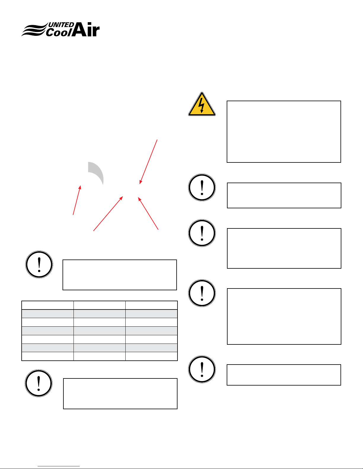
When vertical style units are shipped split, or will be split in
the eld and then reassembled in the space, the condensing
section has refrigerant lines that extend above the top of the
cabinet�
When the unit is assembled these ttings are recessed into
the evaporator section . These ttings extend approximately
5” for all models (Figure 1)�
The space height needs to be sufcient to handle not only
the combined unit height, but also the refrigerant tting
clearance height�
5"
Mounting And Setting In Place
CAUTION
Unit should not be located in space subject
to freezing temperatures�
The VertiCool Classic has been designed to be installed as
a single package oor mounted unit.
Unit is to be mounted on a solid oor or supported on a
full 100% perimeter frame. Attention must be given to oor
loading limitations� Floor should be level in both horizontal
planes�
Before the unit is installed, a thorough study should be made
of the structure and proposed installation location� Careful
consideration must be given to location of wiring, condensate
disposal, ductwork and accessibility for maintenance
or service� It is necessary that a minimum clearance of
36” be allowed on the front of the cabinet� Some air path
congurations will also require side access to the evaporator
section. Sufcient clearance must be provided to slide the
air lter(s) out, either the left or right side.
Consideration must be made for condensate removal, either
with a trap or condensate pump�
The units might be shipped as a single package or they
might be shipped split� Units that have been ordered with
the optional resealable refrigerant ttings can be split in the
eld to accommodate moving into position. Sections are
also bolted together�
When re-assembling the evaporator section to the
condensing section, use a sling or other suitable means that
is sufcient to hold the weight of the section. Use spreader
bars to keep the cabinet from being deformed�
Make sure that the evaporator section is positioned correctly
for the desired air pattern� Care must be taken when lowering
the evaporator section that the refrigerant resealable ttings
are lined up properly and that they are not damaged in this
process� Re-install the fasteners if removed prior�
Figure 1
Subject to change without notice. 20.10-IM (0617)
5
Page 6

Installation, Operation and Maintenance Manual
VertiCool Classic
Unit Vibration Isolation
When installing any oor mounted unit, it is generally not
necessary to provide any unit vibration isolation� However,
some form of vibration isolation may be requested� Please
note that the unit frames have not been designed for corner
point only loading with vibration isolation methods�
1. If spring mounts are to be used, fabricate a frame to
provide support around the entire perimeter of the unit�
Allow sufcient clearance for any door or panel access
that is required to provide eld service or maintenance
on the unit� The frame will also need to be designed
with suitable cross bracing� (Figure 2)
2. If wafe pad or other similar sound vibration materials
are going to be used, the material needs to be placed
under the entirety of the unit base�
Figure 2
Location
Strategically located intake and discharge louvers help to
prevent recirculation of discharge and contaminated air
into the intake air stream. Airow around a building and
prevailing wind direction can adversely affect the potential for
recirculation and should be factored into louver placement�
In some areas, local codes dictate louver location� Maximize
the distance of intake louvers from any exhaust outlet and
other contaminants, people, property lines, etc� Avoid placing
intakes near idling vehicles�
The bottom of the intake louver should be raised a minimum
of 12" from a horizontal surface (roof, sidewalk, etc�) to
prevent blockage from debris� If snow accumulations are
expected to be greater than 12", raise the bottom of the
louver above the average snowfall depth�
If more than one VertiCool unit will be installed in the same
area, then the minimum separation of one unit adjacent
to another should be 6 feet� A 10 foot separation distance
should be maintained where two units are installed one
above the other� It is best to direct discharge air up and away
from pedestrian walkways as well�
We do not recommend multiple installations between closely
situated buildings where discharge air could collect and be
directed back to the intake� Again, recirculation will cause
the unit to trip on high head pressure�
Clearance
Clearance of 36" is required on the front side of all units for
service and maintenance access�
If a unit has front return, 30" clearance on each side of
the unit must be provided for access to the motor and / or
refrigerant circuit components, such as the thermostatic
expansion valve(s)�
Filters can be accessed from either side of the unit. Sufcient
space must be provided for removal and replacement of all
lters. This can be from one side only or from both sides.
Louver And Ducting
Carefully choosing the right condensing section intake/
exhaust louver(s) and determining the best location for them
are critical components to a successful VertiCool installation�
and/or discharge unit openings to allow for optimum velocity
and reasonable pressure drop across the louver�
1. Select a louver design that will safely separate the
discharge from the intake air stream to ensure that air
recirculation will not occur�
2. The intake louver should be designed to minimize and
virtually eliminate water penetration at a reasonable
face area velocity (fpm)�
3. The discharge duct must be as short and straight as
possible but of sufcient length to guarantee uniform
airow distribution through the louver for maximum
velocity�
4. In most cases, the cross-sectional “free area” of the
louver must be equal to or larger than the crosssectional areas of the intake and/or discharge unit
openings to allow for optimum velocity and reasonable
pressure drop across the louver�
5. Ducts should be insulated if the unit is installed and
operating in cold climates�
6. Adequate access to both the evaporator and condenser
coils as well as the louver must be available for
cleaning purposes�
7. All louver manufacturer instructions, local codes, and
industry accepted guidelines must be followed for all
installations�
Subject to change without notice. 20.10-IM (0617)
6
Page 7
Installation, Operation and Maintenance Manual
VertiCool Classic
INFORMATION
Discharge air from the condenser air
outlet should be deected away from the
condenser air inlet, to prevent recirculation�
The intake and discharge louver can be in separate frames
or combined in one frame�
The combination intake/discharge louver design (Figure 3)
offers an advantage over separate louvers because it requires
only one wall opening which decreases installation costs�
However, the blades cannot be of uniform conguration (i.e.
the same blade design and angle)� The discharge louver
blades should be angled to direct the airow straight out
horizontally from the unit and the intake blades should be
angled down at approximately 45°�
Combination Intake/Discharge
D
“D”
“D” Discharge“I” Intake
“I”
It is also benecial to angle the bottom of the intake ductwork
up from the louver toward the unit opening to minimize the
possibility of water carryover reaching the unit and allow for
proper drainage Figure 4)�
Figure 4
Discharge Louver
Access panel for condenser coil cleaning�
Inlet Louver
Louvers should be inspected and cleaned on a regular
basis� A bird screen is required to deter animals and debris
from entering the duct system�
3" Separation Plate
4"
[101�5 mm]
W
Figure 3
It is critical that the two air streams be directed in different
directions so that no recirculation of discharge air is allowed to
enter the inlet air stream� In some cases it may be necessary
to provide a deector vane or separator between the two air
streams� If recirculation of the discharge air does occur, the
unit will likely trip on high head pressure and continue to fail
until the louver design is corrected�
Louvers may be manufactured of aluminum (14 gauge) or
steel (18 gauge)� Louver widths of 30 inches or more should
have additional bracing midway along the blades to maintain
proper blade separation� If the louvers are to be installed
in a coastal application or any location with environmental
concerns, then the louvers should be treated�
Length of Ductwork for Discharge Air
The VertiCool Classic unit should be located a minimum
distance from the louvered wall to maximize efciency of the
blower� Certain conditions and obstructions at the fan inlet
and outlet adversely affect fan performance (i�e� elbows,
guards, dampers, etc�)� “System Effect” is a term used by the
industry to describe these adverse conditions� It is best to
design the inlet and discharge ductwork to provide minimum
sufcient straight length of duct to reduce system effect and
allow for uniform air discharge�
Figure 5 below illustrates the discharge air velocity prole at
various distances from the centrifugal blower� It is important
to determine the 100% Effective Duct Length to ensure
uniform air discharge�
Subject to change without notice. 20.10-IM (0617)
7
Page 8
Installation, Operation and Maintenance Manual
VertiCool Classic
Based on formulas in ASHRAE Fundamentals – Duct Design,
Chapter 34, the following minimum intake and discharge
100% Effective Duct Lengths (EDL) are recommended:
3 thru 5 tons = 3�5 feet
6 & 8 tons = 4 feet
10 thru 15 tons = 5�5 feet
Outlet Area
Blast Area
Cutoff
100% Effective Duct Length
20 tons = 6�5 feet
25 tons = 8 feet
30 & 35 tons = 8�5 feet
25%
50%
75%
Discharge Duct
Figure 5
The VertiCool units are supplied with a standard motor
and drive package which provides approximately 0�25”
ESP� Upgrades (optional) are available that can raise this
capability to 1” ESP or more� The drive packages have some
ability to be adjusted in the eld. You must know the overall
duct design in order to determine what drive package will
be required� Normal start-up procedures should be followed
including balancing the system following the completed unit
installation�
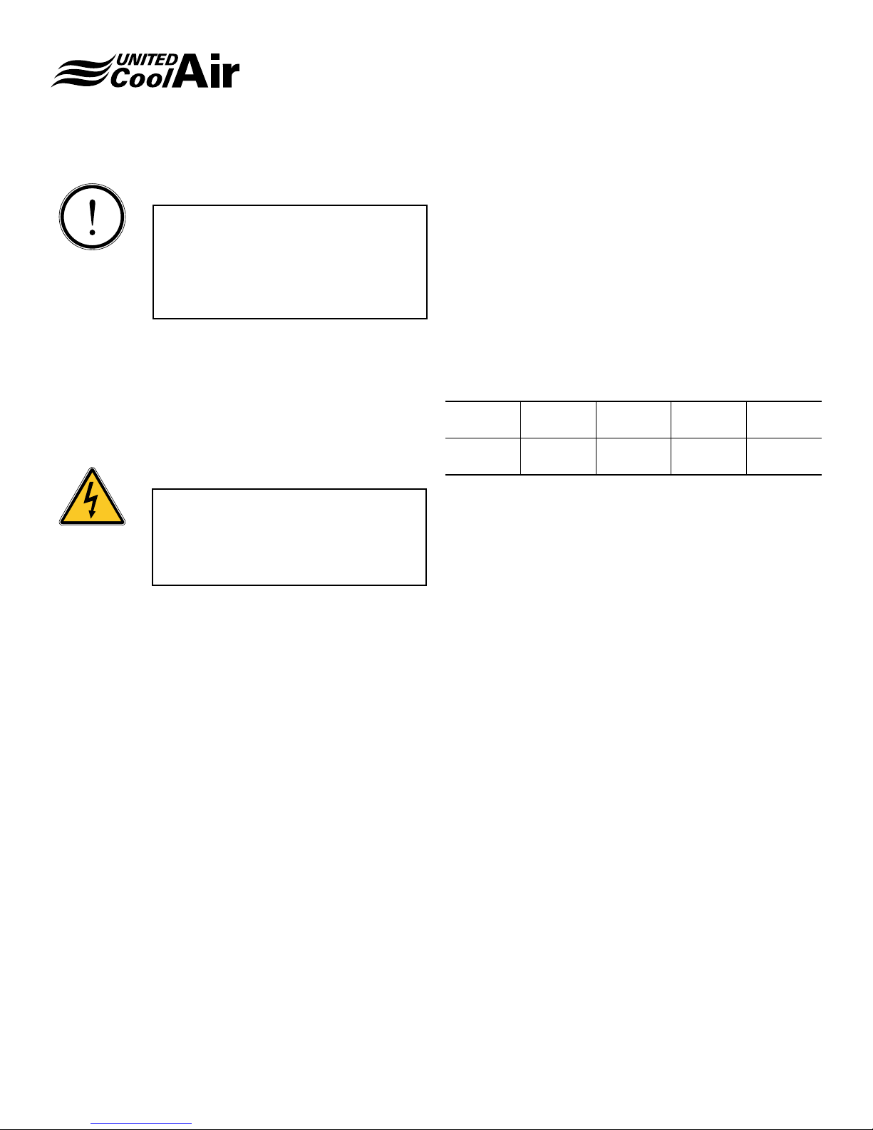
Application Data
Voltage 208 / 230 460 575
Variation 187 / 253 414 / 504 518 / 632
Cooling
(Air Entering Evaporator)
Water-Cooled
DB
(min./max.)
WB
(min./max.)
GPM / Ton
(min./max.)
Leaving Water
(min./max.)
65 / 110
57 / 72
2.5 / 3.5
60 / 115
Installation
The VertiCool Classic units can be shipped as a single
package or as a split package which is assembled in the
eld.
Air-Cooled Single Package
1. Move the unit to the desired installation location�
2. Unit contains a full charge of R-410a refrigerant�
3. Install the unit so that controls and access panels are
accessible to the operator and maintenance personnel�
4. Install the condensing section ductwork following the
guidelines and industry accepted practices for the
condenser air inlet and discharge�
5. Install ductwork on the evaporator as required� If the
unit was provided with a discharge plenum having
grilles, no ductwork would be required�
6. Install the condensate trap as outlined below�
7. Wire the unit as outlined below�
Air-Cooled Units Shipped Split or Split In The
Field For Unit Locating
1. Move the unit to the desired installation location�
2. Unit contains a full charge of R-410a refrigerant�
3. Install the unit so that controls and access panels are
accessible to the operator and maintenance personnel�
4. Install the condensing section ductwork following the
guidelines and industry accepted practices for the
condenser air inlet and discharge�
5. When re-assembling the evaporator section to the
condensing section, use a sling or other suitable means
that is sufcient to hold the weight of the section.
Use spreader bars to keep the cabinet from being
deformed�
6. Make sure that the evaporator section is positioned
correctly for the desired air pattern� Care must be
taken when lowering the evaporator section that the
refrigerant resealable ttings are lined up properly and
that they are not damaged in this process� Re-install
the fasteners if removed prior� Systems shipped split
from the factory will have the mounting hardware
located inside the evaporator section�
7. Install ductwork on the evaporator as required� If the
unit was provided with a discharge plenum having
grilles, no ductwork would be required�
8. Install the condensate trap as outlined below�
9. Wire the unit as outlined below�
Note: Not all combinations may be valid.
Subject to change without notice. 20.10-IM (0617)
8
Page 9

Installation, Operation and Maintenance Manual
VertiCool Classic
General Ductwork Recommendations
1. Please make sure that all duct work, evaporator return
and supply air and for air-cooled units the condensing
section inlet and discharge air, is connected to the units
using eld supplied exible duct connectors.
2. Make sure that all duct work is supported
independently from the equipment�
These two installation requirements are meant to minimize
or isolate any unit vibration to help assure that it is not
transmitted into the duct work, to the structure and/or out
into the space�
All ductwork must be designed in accordance with industry
accepted practices� Consult ASHRAE, AMCA or SMACNA
guidelines or standards for details� Use of turning vanes is
recommended�
Verify that the designed duct external static pressure is in
line with the capability of the unit blower / motor provided�
Ducts should be insulated in accordance with applicable
industry standards or per local codes, particularly if the unit
will be operated during cold weather� The condensing unit
intake duct should include a provision to access the inlet
side of the coil for periodic cleaning� It is also best to design
for sufcient clearances for servicing the blower motors,
expansion valves, lters, and any additional accessories
installed�
This negative pressure can vary from less than 1” up to 2”
column. The condensate trap must be of sufcient depth in
water column to permit the condensate to ow from the drain
pan�
The “A” dimension (Figure 6) must equal or exceed the
negative static pressure developed by the supply air blower�
If it does not, the condensate will not drain properly and
may overow the drain pan. The trap must be at least 2-1/2”
deep to maintain a water seal under all operating conditions,
especially during blower start-up�
It is highly recommended that the trap be primed with water
prior to unit start-up�
Each trap must be piped to a suitable waste drain�
Unit
“A”
2-1/2"
Figure 6
Plenum Installation
The plenum is typically installed at the factory� However, it
may need to be removed to move the unit into position� The
plenum is held in position with drive screws�
If the plenum has discharge grilles, the grilles will have to
be removed to take the plenum off for re-installation on the
evaporator section�
Condensate Drain Connection
Install a eld fabricated condensate trap and drain line or
a condensate pump as required� Route the condensate
disposal tubing to a suitable location�
Units are equipped with two 3/4” IPS evaporator drain
connections� It is only necessary that one drain connection
be utilized� Make sure that the drain connection not being
used is plugged�
The drain line must be trapped because the coils are
located on the negative side of the blower(s)� The purpose
of the condensate trap is to neutralize the negative pressure
created within the cabinet by the blower�
Subject to change without notice. 20.10-IM (0617)
Refrigerant Connections
All units are shipped from the factory with a full factory
refrigerant charge. The resealable refrigerant ttings must
be connected and properly tightened to facilitate refrigerant
ow between the evaporator and compressor / condenser
section�
If the unit has been shipped split or has been split to
accomplish installation, the resealable refrigerant ttings
must be connected as follows:
1. On the refrigerant resealable ttings, if not already
accomplished, apply a few drops (5 to 6 droplets are
recommended) of refrigerant oil to the male coupling
halves before starting the assembly (Ref� to Figure 7)�
2. Align each resealable tting and hand thread the
female tting onto the male tting (Ref. to Figure 7).
Continue to hand thread until resistance is observed�
Continued on next page
9
Page 10
Installation, Operation and Maintenance Manual
VertiCool Classic
3. Once slight resistance is evident, continue to tighten
the ttings using the appropriate size wrenches listed in
Table 1� Please note that it is important to support the
male side of the tting with a wrench when tightening
the female side with a wrench�
4. If the resealable ttings still feel loose, tighten a bit
more as required�
Figure 7
Clockwise Rotation
Female Fitting
Apply oil to male threads Male Fitting
INFORMATION
Count the number of threaded rotations�
Use Table 1 to determine how many total
rotations are required for proper sealing of
the ttings.
Size Wrench Full Turns Required
3/8" 1-3/16" 6
1/2" 1-3/16" 6
5/8" 1-5/8" 7-3/4
3/4" 1-5/8" 7-3/4
7/8" 1-5/8" 8
1-1/8" 2" 8
Electrical
ELECTRICAL HAZARD
Only a qualied licensed electrician or
other individual that is properly trained in
handling live electrical components should
perform the wiring installation� Failure to
follow all electrical safety precautions and
industry accepted practices when exposed
to live electrical components could result
in death or serious injury�
INFORMATION
Use Copper Conductors Only� Failure
to use copper conductors may result in
equipment damage�
INFORMATION
All electrical wiring must be in accordance
with NEC (National Electrical Code), NFPA
(National Fire Protection Agency) most
current versions as well as any applicable
state or local codes�
INFORMATION
The correct phase sequence of the
incoming power supply is a requirement�
If the phase sequence is not correct it
could cause damage or failure to electrical
components� Reverse the incoming wiring
to resolve the issue� Do not switch any
internal unit wiring�
INFORMATION
INFORMATION
If low refrigerant pressure is evident during
the start-up process, check the tightness
of all resealable ttings. A tting that is not
fully open will restrict refrigerant ow.
Subject to change without notice. 20.10-IM (0617)
Conrm that the incoming power supply
matches the unit data tag�
10
Page 11
Installation, Operation and Maintenance Manual
VertiCool Classic
INFORMATION
Unit wiring and components have been
designed for the specic unit application
and factory assigned controls� Do not use
the unit transformers or alter the unit wiring
to interface any eld supplied accessories
or controls�
A factory provided power block is installed internal to the
unit’s electrical control panel� Route the main power wires
in accordance with all codes from the disconnect to the unit
power block�
A proper ground termination lug has been provided in the
unit control panel�
ELECTRICAL HAZARD
Conduit is not an acceptable grounding
source� A separate ground conductor must
be connected from Earth Ground to the
factory supplied grounding lug internal to
the unit�
Transformer
Dual voltage units, 208/230, are wired from the factory
for the 208 volt power supply� If the power supply will be
consistently above 220 volts the transformer should be wired
on the 230 volt tap�
Wiring
1. Refer to the wiring diagram that was included with the
unit�
2. Units are completely internally wired at the factory�
3. All units are provided with terminal blocks�
4. Check the unit data tag for the required voltage,
minimum circuit ampacity and maximum fuse size�
5. Route the power wiring through one of the holes
provided in the front corner posts�
6. Power wiring must comply with all National or Local
codes� The power supply must be suitably fused for
wire protection�
7. Use copper conductors only� The unit must be earth
grounded using the ground lug provided in the electrical
box�
8. Select a location to install the thermostat to avoid
vibration, drafts, sun exposure or internal heat sources�
Use an inside wall�
9. Route the correct low voltage wire type and size back
to the unit and through one of the holes provided in the
front corner posts� Connect to the low voltage terminal
block per the wiring diagram supplied�
Wire Size1 AWG. Gauge
22 20 19 18 16
40 120 150 190 305
Maximum Wire Length2 Feet
Notes:
1. Soilid, Class II copper wire
2. Based on a voltage drop of 1�2 volts per wire�
3. Total wire length is from unit to room thermostat, and
back to unit�
Three Phase Power
On units with three phase power supply, check for proper
blower rotation� If they are running backwards, interchange
two of the incoming power leads�
Do not rewire any components inside the unit�
Electric Heat
On larger units having a high amount of electric heat, a
second power supply may be required� Run the second
power supply to the connections located with the heater�
Follow all National Electrical Codes and Local Codes as
required� Make sure to run a ground wire to the supplied lug�
Route the low voltage wiring for the heater control to the low
voltage terminal block located with the heater�
Subject to change without notice. 20.10-IM (0617)
11
Page 12
Installation, Operation and Maintenance Manual
VertiCool Classic
Voltage Unbalance
Voltage unbalance occurs when the RMS line voltages on
a 3-phase power supply are unequal� Voltages are never
balanced between phases, but if the level of the unbalance
becomes excessive it will create problems for not only
motors but also controls�
The maximum desirable voltage unbalance is 2�0%�
When testing for voltage unbalance, the phase-to-phase
voltages should be measured rather than the phase-toneutral voltages since 3-phase motors are connected across
phases� Use the following formula to determine the percent
of voltage unbalance:
Percent Voltage Unbalance = 100 x (Maximum Voltage
Deviation / Average Voltage)
Example:
Phase-Phase voltages
A-B = 479V
B-C = 472V
C-A = 450V
Average Voltage = (479 + 472 + 450) / 3 = 467
Maximum Voltage Deviation from Average =
467 - 450 = 17 (Must always be positive)
Voltage Unbalance = 100 x (17/467) = 3�6%
In this example the percent of voltage unbalance exceeds the
desired maximum of 2%� Additional checks should be made
at the unit disconnect to conrm the values. Use accepted
industry practices to check or test the quality of the power
supply� Often, it is just a matter of repairing malfunctioning
equipment or redistributing loads to improve the unbalance�
If no cause can be located and resolved for the unit power
supply, the building manager or owner should be notied of
the issue to get the proper power supplied to the unit�
It should be noted that the inclusion of a variable frequency
drive (VFD) with an unbalanced power supply may result in
nuisance tripping and 3rd harmonic currents�
Chilled Water Coil Valves Or
Hot Water Coil Valves
Chilled water or hot water valves, if supplied by United
CoolAir, are typically 2-way� The optional valves are shipped
loose for installation in the eld. The valves are to be mounted
in the outlet line of the coil�
Pressure Switches
High Pressure
This switch shuts the unit down in the event of excessive high
pressure in the discharge line� A manual reset is required at
the high pressure switch�
Low Pressure
This switch shuts the unit down in the event of low pressure
in the suction line� This switch is auto-reset�
Water-Cooled Units
INFORMATION
Do not reduce the water inlet or outlet
connection size as this will restrict water
ow and increase water pressure drop.
CAUTION
Ensure that the water pressure to the unit
does not exceed any valve rating�
INFORMATION
All eld installed piping must conform to
applicable local, state and federal laws�
The following items are to be eld supplied and applied:
A. Water shut-off valves (Gate or Ball Type)
B. Inlet water strainer with isolation shut off valves on
each side for periodic cleaning�
The standard condenser heat exchangers are co-axial type�
These are tube-in-tube type that are chemically cleanable�
The inner tube carries the water and the outer tube the
refrigerant� When designing and installing the water piping,
some consideration for the chemical cleaning should be
made, if desired, for future maintenance�
CAUTION
The condensate drain line should not be
connected to the condenser outlet, as
ooding will occur.
Subject to change without notice. 20.10-IM (0617)
12
Page 13

Installation, Operation and Maintenance Manual
VertiCool Classic
INFORMATION
It is advantageous to record the inlet and
water outlet temperatures and the heat
exchanger pressure drop during the unit
start-up procedure� These are then a
valid reference point for maintenance
considerations in the future�
INFORMATION
Field supplied water piping must include
a pet cock or other suitable means at the
highest point to bleed air from the water
piping�
INFORMATION
High inlet water temperature or low water
ow rate may result in nuisance tripping of
the refrigerant high pressure switch�
INFORMATION
Water-cooled units with a glycol cooling
uid will require a higher GPM / Ton ow
rate� Contact the factory for details�
WARNING
Water-cooled units have been designed
for use with fresh water application only�
Do not use for brackish water or salt water
unless appropriate condenser and water
piping has been applied�
INFORMATION
Units have been tested at the factory
before shipment. The test uid at the
factory contains a glycol mixture� It is
important to ush the internal unit piping
and heat exchangers at the job site prior to
start-up or connection to the cooling uid
circuit being used�
Water Piping and Connections
Both the water inlet and outlet of the condensing section
should be equipped with eld supplied shut off valves. This
is needed for shutdown of water supply during long periods
of unit shutdown and/or condenser removal, if required�
If the unit does not have water regulating valves or head
pressure control valves, eld supplied balancing valves may
be required�
INFORMATION
Optional Head Pressure Control Valve(s)
should be incorporated into the unit water
circuit(s) if the cooling uid will be less
than 65° F�
Install and connect a fresh water strainer (eld supplied) to
the water inlet line� Strainer should be readily accessible for
periodic cleaning� Shut off valves on both strainer inlet and
outlet are recommended to facilitate cleaning�
Chilled Water Sections
The chilled water section may be supplied with the lower
section for oor mounting. The chilled water section can also
be supplied as a standalone section�
When being used as a standalone chilled water section, care
must be taken to properly support the section if suspended�
It is advisable to provide a full perimeter frame to assure that
the sheet metal does not buckle�
Provide eld supplied and installed vibration isolation as
required�
Care must be taken when mounting the chilled water section
to assure that adequate service clearance is provided for
access to the components� Make sure that the access
panels can be removed�
The chilled water section will have a control panel�
Dependent upon the system components, this control panel
may be located internal to the evaporator or externally� Wire
high and low voltage to this section as required following
National Electrical Codes or Local Codes�
On larger units having a high amount of electric heat, a
second power supply is required� Run the second power
supply to the connections located with the heater� Follow
all National Electrical Codes and Local Codes as required�
Make sure to run a ground wire to the supplied lug�
Install the chilled water valve per industry accepted practices�
Subject to change without notice. 20.10-IM (0617)
13
Page 14

Installation, Operation and Maintenance Manual
VertiCool Classic
System Options
Humidier
The optional steam humidier that comes with the unit
functions on the electrode principle. As water lls the plastic
steam generator, it immerses metal electrodes then permits
electrical current ow through the water. This current ow
produces heat which then boils the water into steam� This
steam is then injected on the downstream side of the cooling
coil to provide humidication for the area being served by
the unit� Water is replenished through tubing and the 1/4”
are located on the evaporator section structure. For further
information refer to the Humidier Installation Instruction
which accompanies the unit�
INFORMATION
The humidier should not be subjected
to freezing air conditions� If the unit will
be used for outside air applications an
externally mounted humidier should be
used�
Auxiliary Coils (Hot Water or Steam)
A hot water coil or steam coil when used as heat will be
located in the return air stream between the lters and the
evaporator coil� These are typically installed at the factory�
Some units will include Jack Stands to support the auxiliary
coil / lter box. If the unit is shipped as a single package the
jack stands will be attached� Care should be taken when
moving the unit from the skid to the installation location so
as not to tear or loosen the jack stand where it is attached
to the cabinet�
If the evaporator section is shipped loose the auxiliary coil
section will be attached to the evaporator� The jack stands,
if required, will be placed inside the auxiliary coil section�
The mounting hard- ware will be attached to the jack stand
ange.
If an optional hot water valve is ordered, this will be shipped
loose for installation in the eld.
Control wiring will need to be installed from the hot water
valve back to the unit control panel� Follow all National
Electrical Codes and Local Codes as required�
Any steam valves and other adjunct steam components are
to be eld supplied and installed by others.
Control wiring will need to be installed from the steam valve
back to the unit control panel� Follow all National Electrical
Codes and Local Codes as required�
A pan is included under any hot water coil or steam coil� A
condensate trap will need to be installed for this drain pan� A
trap will need to be installed since this line is in a negative air
stream� Follow the same procedures for this line as for the
unit condensate drain line outlined on page 6�
Pipe the hot water coil or steam coil per industry accepted
practices�
Water Side Economizer (Free Cooling Coil)
A water side economizer coil will be located in the return air
stream between the lters and the evaporator coil. These
are typically installed at the factory�
Some units will include Jack Stands to support the water
side economizer / lter box. If the unit is shipped as a single
package the jack stands will be attached� Care should be
taken when moving the unit from the skid to the installation
location so as not to tear or loosen the jack stand where it is
attached to the cabinet�
If the evaporator section is shipped loose the water side
economizer section may or may not be attached to the
evaporator� The jack stands, if required, will be placed inside
the water side economizer section� The mounting hardware
will be attached to the jack stand ange.
If the unit is shipped as a single package, the water piping
from the unit to water side economizer coil will be factory
installed�
If the water side economizer is shipped as a separate section
or if the unit comes with the evaporator and water side
economizer as a section, the water piping will be shipped
loose for eld attachment.
Air Side Economizer
The air side economizer option is installed on the rear of the
cabinet�
Some units will include Jack Stands to support the air side
economizer / lter box. If the unit is shipped as a single
package the jack stands will be attached� Care should be
taken when moving the unit from the skid to the installation
location so as not to tear or loosen the jack stand where it is
attached to the cabinet�
If the evaporator section is shipped loose the air side
economizer section may or may not be attached to the
Continued on next page
Subject to change without notice. 20.10-IM (0617)
14
Page 15

Installation, Operation and Maintenance Manual
VertiCool Classic
evaporator� The jack stands, if required, will be placed inside
the air side economizer section� The mounting hardware will
be attached to the jack stand ange.
The enthalpy sensors for the return air and the outside air
are shipped loose for eld mounting. Follow the instructions
with each sensor for the proper location and mounting�
Field supplied low voltage wiring must be installed between
the two sensors and the terminal blocks located in the unit
control panel� Make sure to use the correct type and wire
gauge size�
When ducting to the air side economizer, exible duct collars
should be utilized to avoid any transmission of vibration into
the duct work�
Split Systems
Systems can be eld modied as a split system option.
Evaporator Mounting
In some situations it is necessary to install the system split�
The evaporator section may be supplied with the lower
section for oor mounting. The evaporator can also be
supplied as a standalone section�
When being used as a standalone evaporator section, care
must be taken to properly support the section if suspended�
It is advisable to provide a full perimeter frame to assure that
the sheet metal does not buckle�
Provide eld supplied and installed vibration isolation as
required�
Care must be taken when mounting the evaporator to assure
that adequate service clearance is provided for access to
the components� Make sure that the access panels can be
removed�
The evaporator section will have a control panel� Dependent
upon the system components this control panel may be
located internal to the evaporator or externally� Wire high
and low voltage to this section as required following National
Electrical Codes or Local Codes�
INFORMATION
Make sure to use the appropriate gauge
of low voltage wire based on the total wire
length so that no more than a 1�2 volt drop
is experienced�
On larger units having a high amount of electric heat, a
second power supply may be required� Run the second
power supply to the connections located with the heater�
Follow all National Electrical Codes and Local Codes as
required� Make sure to run a ground wire to the supplied lug�
Interconnecting Refrigerant Tubing
After the two system sections have been installed, the eld
supplied interconnecting tubing can be run�
(a) Units 10-ton and smaller are provided as standard without
the resealable ttings. In this situation the sections may
be provided with stubbed copper tubing� Follow industry
accepted practices for brazing the eld supplied tubing to the
unit copper tube stubs�
(b) For units supplied with the resealable refrigerant ttings follow
instructions below�
Units are provided with unique self-sealing ttings (Optional
on 10-ton and smaller, standard on 12-ton and larger) on
the refrigerant lines between the sections. These ttings or
couplings allow the two section unit to be separated and
reconnected without loosing the refrigerant charge�
When installed as a split system, an optional interconnect kit
is required for each refrigerant circuit or hot gas bypass line�
If the unit was dened as a split system when ordered, the
ttings will be male on both sections. The interconnect kit will
then consist of the matching female ttings. An interconnect
kit is required for the installer to connect refrigerant lines
between both sections� Refrigerant piping between the
sections is eld supplied.
Systems not ordered from the factory to be installed as a
split system, and that contain resealable ttings, will include
Female Fittings on the evaporator section and Male Fittings
on the condensing section� An optional Interconnect kit(s)
must be ordered indicating that a Male / Female Kit is
required�
The interconnect kit also contains four (4) Schrader ttings.
The installer can place at least one in each refrigerant line or
at one end of the refrigerant line� These enable the refrigerant
line to be evacuated and charged as needed, based on the
size and length�
In some situations, the desired refrigerant line size may
differ from the self-sealing tting size provided. The line size
should be reduced or enlarged at the self-sealing ttings as
necessary�
INFORMATION
On units with more than one refrigerant
circuit, be careful not to intermix liquid,
suction and/or hot gas lines of the various
circuits�
Subject to change without notice. 20.10-IM (0617)
15
Page 16

Installation, Operation and Maintenance Manual
VertiCool Classic
1. Temporarily hand thread the female halves of the selfsealing couplings (supplied with the interconnect kit)
onto the male couplings, approximately 1 to 1-1/2 turns�
This is to make sure that the interconnecting tubing will
be routed and brazed with the self-sealing couplings
in their nal proper location, so that there will be no
difculty when the nal coupling assembly is made.
2. If there is a hot gas bypass option, connect that
coupling the same way�
3. Run the interconnecting tubing required� Always follow
accepted industry practices for sizing refrigerant
lines based on line length and elevation differences�
Disconnect the self-sealing couplings that were
temporarily installed in step 1 above�
4. The suction line should be pitched downward to the
compressor, sloping approximately 1/4” every ten feet
to facilitate oil return�
5. “P” traps (eld supplied) are required for all suction
line risers every 15 feet� When the evaporator is above
the condensing section, an inverted “P” trap should be
incorporated as close as possible to the evaporator
(this minimizes ood back / oil slugging during the off
cycle)� If the condensing section is more than 40 feet
above the evaporator, consult the factory for specic
refrigerant components�
INFORMATION
On units with more than one circuit, be
careful not to intermix liquid, suction, and/
or hot gas lines of the various circuits�
7. Leak check line sets with nitrogen at 500 psig� After
brazing the tubing to the self-sealing coupling halves,
evacuate each line to 300 microns� Check to make
sure that each line holds a vacuum after removal of the
vacuum pump (indicating no leaks) (micron level should
not go above 500 microns within 10 minutes)� Wipe
off coupling seals and threaded surfaces with a clean
cloth to prevent the inclusion of dirt or foreign material
into the system� Lubricate rubber seal and metal seal in
the male halves with refrigeration oil� Thread coupling
halves together by hand to insure proper mating of
threads� Continue to hand-thread each half-coupling
to its mating half until resistance is felt (approximately
1-1/2 to 1-3/4 turns)� Complete the connection of the
mating half-couplings with a wrench� If the resealable
ttings still feel loose, tighten a bit more as required.
INFORMATION
Count the number of threaded rotations�
Use Table 1 to determine how many total
rotations are required for proper sealing of
the ttings.
Size Wrench Full Turns Required
3/8" 1-3/16" 6
1/2" 1-3/16" 6
5/8" 1-5/8" 7-3/4
3/4" 1-5/8" 7-3/4
7/8" 1-5/8" 8
1-1/8" 2" 8
Table 1 - Resealable Fitting Turns
INFORMATION
When brazing tubing to the self-sealing
couplings, use a water soaked wet rag,
running water bath or chill blocks on the
quick-connects to prevent overheating the
valves and damaging the seals� Always
apply heat toward the eld installed
refrigerant line� Do not apply heat toward
the coupling valve and seal�
6. Install the Schrader valve ttings into the tubing before
brazing the couplings onto the ends of the tubing� Use
a 1/4" hole to mount the valve� Clean and debur the
tubing before doing any brazing to ensure that no chips
or debris are left in the refrigerant circuit� Remove the
Schrader valve cap and core before doing any brazing�
Subject to change without notice. 20.10-IM (0617)
INFORMATION
If low refrigerant pressure is evident during
the start-up process, check the tightness
of all resealable ttings. A tting that is not
fully open will restrict refrigerant ow.
The drawing below illustrates a typical piping arrangement
for factory ordered split systems
A - Male self-sealing ttings on unit sections
B - Refrigerant piping between sections (eld-supplied)
C - Female self-sealing ttings in interconnect kit (4)
D - Schrader ttings in interconnect kit (4)
16
Page 17

Installation, Operation and Maintenance Manual
VertiCool Classic
A
Evaporator
Section
A
D
C
D
C
D
B
D
B
C
C
A
Condensing
Section
A
8. Size refrigerant lines per industry accepted practices�
9. Refrigerant piping shall be insulated in accordance with
local codes and / or applicable ASHRAE Standards�
Insulation exposed to weather shall be suitable for
outdoor use� Provide protection from water and
shielding from solar radiation as necessary�
10. Max. total equivalent line length is 100 feet.
(a)
Max. elevation difference between Evap. And Cond.
Is 40 feet.
(a) Contact the factory for installations with elevation
differences greater than 40 feet or total equivalent
lengths greater than 100 feet� Alternate line sizes and
specic additional refrigerant circuit components may be
required�
(b) If condensing section is 20 feet or more above the
evaporator an oil separator is to be included for each
circuit�
(a) (b)
11. Split must contain refrigerant circuit items as follows:
Equivalent Feet
Oil Separator
Accumulator
Quench Valve
Solenoid Valve
Liquid Line
c. For 5/8” liquid line – add 1�8 oz� per foot
d. For 7/8” liquid line – add 2�4 oz� per foot
Condensate Pump
If an optional condensate pump is to be used, it will be
mounted external to the unit�
Follow pump manufacturer instructions�
A 115 volt power supply must be eld supplied for the pump.
INFORMATION
The condensate line out of the unit must be
trapped before going into the condensate
pump�
Refer to Figure 8 for the termination of the condensate tubing
inside the pump�
Refer to Figure 9 for the inverted “U” trap that is to be installed
for the condensate line�
Cut tubing at an angle so
that bottom of reservoir
doesn’t close it� Be sure
tubing does not interfere
with oat.
Discharge Line > 100 X
Ext. Hot Gas Bypass Line > 50 X
Liquid Line Net Down >50 X
Suction Line >100 X X X
Suction Line Ambient > 100° F >50 X X
Suction Line Down > 50 X
12. Add the appropriate charge of R-410a Refrigerant
using the Schrader valves to compensate for the
additional interconnecting tubing as follows:
a. For 3/8” liquid line – add 0�6 oz� per foot
b. For 1/2” liquid line – add 1�2 oz� per foot
Subject to change without notice. 20.10-IM (0617)
Max� Pump Lift
17
Figure 8
To
Drain
Inverted
“U” Trap
Figure 9
Page 18

Installation, Operation and Maintenance Manual
VertiCool Classic
Controls
Thermostat
Conrm that the correct thermostat is being applied based
on the number of cooling stages and heating if applicable�
Follow the thermostat manufacturer instructions�
Microprocessor Controller
For units controlled by a microprocessor refer to the specic
instructions for that device�
Flooded Condenser
When the outdoor ambient temperature falls, the condensing
pressure falls� This causes the discharge pressure to fall�
Since the pressure differential across the thermostatic
expansion valve port affects the rate of refrigerant ow, low
discharge pressure generally causes insufcient refrigerant
to be fed to the evaporator. Failure to have sufcient head
pressure will result in low suction pressure and/or iced
evaporator coils�
The purpose of a ooded condenser is to hold back enough
of the condensed liquid refrigerant so that some of the
condenser coil surface is rendered inactive� This reduction
of active condensing surface results in a rise in condensing
pressure and sufcient liquid line pressure for normal system
operation�
The effective range for this option is down to –30° F�
A three–way modulating valve and a receiver tank make up
the ooded condenser refrigerant components.
The valve is placed in the liquid line after the condenser coil�
The receiver is downstream of the valve� The valve limits
the ow of liquid refrigerant from the condenser while at the
same time regulating the ow of discharge gas around the
condenser to the receiver�
During periods of low ambient operation, the receiver
pressure falls until it approaches the setting of the control
point of the valve (typically 295 psig for R-410a)� The valve
then throttles to restrict the ow of liquid from the condenser.
This raises the condenser pressure� Since it is the receiver
pressure that is being maintained, the valve will then start
to throttle open the discharge port when the differential
between the condensing pressure and the receiver pressure
exceeds 20 psi� The hot discharge gas serves to heat up the
cold liquid being passed from the condenser to the receiver�
Thus the liquid reaches the receiver warm and with sufcient
pressure to assure proper expansion valve operation�
The receiver is required to hold all the excess/additional
liquid refrigerant in the system, since the refrigerant will be
returned to the receiver when the high ambient conditions
exist�
In the off-cycle the refrigerant can “migrate” to the condenser,
during periods of low outdoor ambient� On a call for startup, the evaporator pressure may not build up to the cut-in
point of the low pressure control� The result may be a failure
of the compressor to start or to short cycle� To eliminate
this potential problem, a time delay is added to bypass the
low pressure switch during start-up to allow the discharge
pressure to build, in turn increasing the suction pressure�
Subject to change without notice. 20.10-IM (0617)
18
Page 19

Installation, Operation and Maintenance Manual
Maintenance Procedures
VertiCool Classic
ELECTRICAL HAZARD
Turn OFF power and lockout service
before conducting any maintenance� Keep
hands, clothing and tools clear of electrical
terminals�
WARNING
Make sure to keep hands and clothing
clear of any moving belts, blowers and
motors while performing any maintenance�
Failure to do so could result in death or
serious bodily injury�
CAUTION
Any maintenance should be conducted
by qualied HVAC service personnel only.
Potentially hazardous situations which
may result in personal injury, equipment or
property damage�
Filters
Do NOT run unit without lters.
Throwaway lters are supplied which are pleated extended
surface type� Filters should be checked monthly for dirt
accumulation and changed when necessary� Replacement
lters must be the same type as originally supplied.
INFORMATION
Unit must be shut off at the disconnect
switch before the lters are serviced. Be
sure to check that the air ow direction
arrows on the lters point in the correct
direction of air ow.
Cleaning The Water-Cooled
Condenser
Any uid that is used to carry the heat away through the
condenser contains, minerals, dust from a cooling tower or
other foreign materials� Over time these contaminants will
build up on the walls of the heat exchanger�
This scale or fouling will result in a reduction in water ow,
less water temperature difference between inlet and outlet,
high condensing temperature and higher uid pressure drop.
All of these affect the operating performance and efciency
of the system and need to be addressed�
Cleaning a water-cooled condenser helps to improve the
heat transfer rate, reduce operational cost, restore efciency,
prolong heat exchanger life and reduce pressure drop
pumping costs� Deposits from water or water treatments,
such as scale, lime, rust or mud are removed�
Each installation is unique. Therefore, the uid quality and
operating conditions will dictate when the heat exchanger
needs to be cleaned�
During the start-up process record the water pressure drop
across the heat exchanger� Also record the inlet and outlet
water temperatures� After a period of time these values can
be checked to see how much loss of operating performance
has occurred� If a 10% or greater change has occurred, it
would be benecial to clean the heat exchanger.
There are a number of commercially available products for
cleaning a heat exchanger� Follow all industry practices to
safely and effectively clean the heat exchanger�
Blowers
Disconnect power and lockout the service before doing any
service or maintenance�
Air-cooled units are provided with adjustable belt drive
blower packages for both the evaporator and condensing
sections� Check that the blower wheel is tight on the shaft
and does not contact the housing� Bearings are permanently
sealed, but should be checked periodically for signs of wear�
Check for restrictions or foreign material in the air circuit�
The drive may be adjusted for different static pressures� If
such an adjustment is made, check that the motor current
draw does not exceed the motor nameplate current by more
than 10%�
Blower Motors
All blower motors are equipped with thermal overload
protectors�
WARNING
Open disconnects to unit before doing
any service or maintenance� A motor that
is off on thermal overload can start any
time when the automatic thermal overload
resets�
Subject to change without notice. 20.10-IM (0617)
19
Page 20

Installation, Operation and Maintenance Manual
VertiCool Classic
Blower Speed Adjustment
Blower speed may be changed by adjusting the variable
diameter sheave provided on the blower drive motor�
Sheave may be adjusted by removing the belt and loosening
the setscrew located in the hub of the outer ange. With the
setscrew loosened, the ange may be turned clockwise
to increase blower speed or counter-clockwise to reduce
blower speed�
Typically the motor and drive packages have been sized and
designed for the specic CFM and external static pressure
(ESP) of the application. Before making any changes conrm
what the performance was designed for and what the actual
performance is�
INFORMATION
Setscrew must be positioned directly
above the at section of the threaded
sheave shaft before tightening to hold
adjustment�
INFORMATION
Reduction of airow through excessive
external air friction losses, lowered blower
speed operation with dirty lters, or
obstructed air ow may result in excessive
condensation at air outlets, short cycling,
or total unit shut- down due to evaporator
coil icing�
INFORMATION
Verify that the motor current draw does
not exceed the motor nameplate current
by more than 10%�
Blower Bearing Lubrication
INFORMATION
Unit must be shut off at the disconnect
switch before the blowers are serviced�
Bearings on the smaller units are permanently sealed, but
should be checked periodically for signs of wear�
Larger units have pillow block bearings� Bearings will need
to be lubricated based on the use of the equipment�
Duty Grease Interval
Low Usage 12 Months
Periodic 6 Months
Continuous 1 – 2 Months
Use a high quality lithium grease for blower pillow block
bearings. Wipe off the “Zerk” tting with a rag before adding
grease so as not to introduce dirt into the bearing�
Slowly rotate the shaft while pumping it in� Pump the grease
in slowly so as not to blow out the bearing seal� When the
grease starts to “seep” out of the bearing you have put in
enough new lubricant�
Over lubricating can cause a bearing to fail from overheating
or it can blow out the seal�
Both excessive or inadequate grease may cause premature
failure� Provided there is some grease in the bearings for
lubrication, under lubrication is better than over lubrication
as grease can easily be added but not removed� Always
allow a slight bead around the circumference of the seals to
protect the bearing from foreign matter and helps ush out
the bearing as well�
Wipe off the “Zerk” tting with a rag after adding grease
Belts
Excessive belt tension is the number one cause for blower
bearing failure� Proper belt tension and pulley alignment are
essential for trouble free operation�
Deection is the amount the belt gives when force is applied,
usually by nger, to the belt at the approximate center point
to the belt span�
Insufcient deection indicates that the belt tension is
entirely too tight, and if not loosened somewhat, noise due
to excessive vibration, premature bearing failure, shortened
belt life, and a reduction in supply air blower performance
may result� Tight belts may also overload the motor and
cause the efciency to drop considerably or even premature
motor failure as well�
Excessive deection is an indication that the belt is not tight
enough� If not corrected, slippage may occur causing loss of
blower speed and belt failure� The belts will glaze then crack
or even break due to increased temperatures caused by
slippage� Belts may slip during start-up, but slipping should
stop as soon as the fan reaches full speed�
If the midpoint (midway between the blower and motor shaft)
of the belt is pressed inward, there should be about 1/2” to a
1” of deection when the belt is properly tensioned.
Subject to change without notice. 20.10-IM (0617)
20
Page 21

Installation, Operation and Maintenance Manual
VertiCool Classic
Refer to Figure 10 – Belt Tensioning below�
Deection Point
Belt Span
Figure 10 – Belt Tensioning
For proper tensioning, an excellent method to use is listed in
the following equation�
Deection = Belt Span
64
Belt span is in inches from center pulley to center pulley (see
Figure 10)�
Belt tension is adjusted by using the adjusting bolt on the
end of the motor mounting frame�
Check the alignment of the sheaves to make sure that the
sheave faces are in the same plane� Check this by placing
a straight edge across the face of the sheaves� Any gap
between the edge and sheave faces indicates misalignment
When the indicator is pink or purple, an abnormal condition
exists, servicing is required�
INFORMATION
After installation and during equipment
start-up, the sight glass may appear pink
or purple� This occurs during prolonged
periods of non-operation and should turn
blue after several hours (up to 12) of
operation�
Evaporator And Air-Cooled
Condenser Coils
The nned coils in a unit should be checked at least every
six (6) months or more frequently based on experience of
the specic application.
Evaporator nned coils can become “fouled” due to a build
up of contaminants in the air path that are not caught or
captured in the air lters. Over time this build up on the n
surface can reduce heat transfer and increased resistance
to air ow. The end result might be higher operating costs or
occupant discomfort
A dirty condenser coil will cause high condensing pressures,
resulting in higher power consumption and possibly system
shut-down by high pressure safety control� A dirty evaporator
coil will reduce unit capacity and eventually will cause system
shut-down by the low pressure safety control�
Finned Coil Cleaning
Note: This alignment method is only valid when the width of
the surfaces between the belt edges is the same for
both sheaves. When they are not equal or when using
adjustable pitch pulleys, adjust so that the belts have
approximately equal tension. Both shafts should be
at right angles to the belt. Check the setscrew and/or
bushing bolt tightness.
Belts tend to stretch somewhat after installation� Recheck
belt tension after several hours of operation�
Refrigerant Systems
All refrigerant circuits contain a liquid line sight glass� If
bubbles appear in the sight glass, the system is either
undercharged with refrigerant or there may be a restriction in
the liquid line upstream of the sight glass� However, bubbles
will appear every now and then in units with the hot gas
bypass option� Bubbles will also appear upon compressor
start up, but normally clear to pure liquid after a few minutes
of operation�
The sight glass contains a moisture indicator which changes
color when moisture is present in the refrigerant circuit� This
indicator is the circular dot in the center of the sight glass�
If the color of this indicator is blue, the refrigerant is okay�
Subject to change without notice. 20.10-IM (0617)
Before cleaning any nned coils, remove the lters. Remove
any large debris or visible dirt accumulation�
WARNING
Make sure to follow all safety precautions
when cleaning any coil with a commercially
available coil cleaner� Follow all
recommendations for safety clothing and
gear� Failure to follow all safety instructions
could result in death or serious injury�
CAUTION
Clean coils only with cold water and a
suitable detergent or a commercially
available coil cleaner� DO NOT use hot
water or steam to clean a coil containing
refrigerant as this may cause a high
pressure situation that could damage
the coil and associated safety devices or
refrigerant components�
21
Page 22

Installation, Operation and Maintenance Manual
VertiCool Classic
CAUTION
Conrm that any coil cleaning agents,
detergents or solutions are suitable for
use on a copper tube/aluminum n coil. If
the cleaning agent is to acidic or alkaline,
damage to the coil ns may result.
Rinse all coils thoroughly after any coil cleaning�
Use a suitable n comb after the coil cleaning to straighten
any bent ns.
Water Side Economizer Coil
If a unit contains the optional water side economizer coil it
may also require a periodic cleaning� These coils will need
to be cleaned using a chemical solution� These are available
commercially� Follow all manufacturer recommendations
and safety warnings�
Water Valves
At least once a quarter check the water vales to make sure
that no leaks are present� Look at the valve stem and all
piping joints�
If any leaks are found follow the manufacturers
recommendations for tightening any seals or replacing any
gaskets�
Hard Start Kit
A start assist device is utilized on all single phase units� The
purpose of this device is to assist the compressor in starting
under low voltage conditions�
A capacitor in conjunction with a Positive Temperature
Coefcient (PTC) relay is installed across the run and
start windings of the motor� The PTC device utilizes a
ceramic element with a predictable thermal response to
the introduction of electric current� When the compressor is
called upon to start, the start capacitor provides a voltage
boost to the start winding of the motor and causes the motor
to turn� As the starting current is introduced across the start
windings, the PTC element begins to warm� When the PTC
device reaches approximately 250° F (corresponding to 0�6
- 0�8 seconds), the resistance in the element increases and
creates an open switch that releases the start winding from
the circuit and the motor continues to run� If the compressor
does not start before the device heats to 250° F, it will not
start until the PTC device cycles through a cool-down period
(usually 2 - 3 minutes)� A compressor off-cycle timer is
included in the electrical circuit for this purpose�
The time delay also helps the refrigerant system pressures
to equalize at the end of the run cycle� This helps the
compressor during the starting process in that it is not
attempting to start against a high discharge pressure�
INFORMATION
Verify that this timer is set for 3 or more
minutes�
Checking Hot Gas Bypass Valve
1. Connect a calibrated thermocouple lead to the outlet
line at the hot gas bypass valve� Tie wrap and insulate
the lead�
2. Connect a low pressure refrigerant gauge to the suction
line�
3. Connect a high pressure refrigerant gauge to the liquid
line�
4. Operate the air conditioner in the cooling mode until the
system is stabilized� (Approximately 15 minutes)
5. If the high side pressure is not at or above 400 psig,
block off the condenser inlet air stream until the
pressure is above this threshold� This will simulate
system performance level close to the design condition
of 95° F ambient�
6. The hot gas bypass valve setting is 104 psig�
A. If the suction pressure is 104 psig the
thermocouple reading should be approximately
117° F or higher� Please note that it may be
necessary to block off some of the evaporator air in
order to check this condition�
B. If the suction pressure is above 104 psig the
thermocouple reading should be less than 117° F�
C. If the suction pressure is below 104 psig the hot
gas bypass valve should be adjusted to raise the
pressure�
Adjustment Of Hot Gas Bypass Valve
The function of the hot gas bypass valve is to prevent the
suction pressure from falling below a predetermined set
point, thereby balancing the system� The set point is typically
104 psig (R-410a)�
1. Connect a low pressure refrigerant gauge to the suction
line�
2. Operate the air conditioner in the cooling mode until
system is stabilized� (Approximately 15 minutes)
3. Remove the seal cap that covers the adjustment screw
of the hot gas bypass valve�
4. Adjust the valve by turning the stem� A CLOCKWISE
turn will increase the pressure setting� A
COUNTERCLOCKWISE turn will decrease the
pressure setting� One complete turn is equal to
approximately 4 psi change�
Subject to change without notice. 20.10-IM (0617)
22
Page 23

Installation, Operation and Maintenance Manual
VertiCool Classic
Adjustments should be made in small increments,
allowing the system to stabilize after each turn.
5. Vary the evaporator load to test at various conditions
that the suction pressure does not fall below the set
point (104 psig for R-410a)�
6. Replace the seal cap on the hot gas bypass valve�
Sequence Of Operation Cooling - - Air-Cooled
The following sequence is based on the unit being controlled
by a suitable room thermostat� If another control type is being
utilized, reference the instructions for that device�
a. Raise thermostat set point to highest level�
b. Set System switch to “OFF” position�
c. Set Fan switch to the “AUTO” position�
d. Moving the Fan switch to the “ON” position should
cause the evaporator blower motor to run� Moving the
Fan switch back to “AUTO” should stop the blower�
e. Move the System switch to the “COOL” position�
Slowly lower the thermostat setting to call for cooling�
The evaporator blower should start (assuming the
Fan switch is set to “AUTO”) and the System lead
compressor should start� The condenser blower on an
air-cooled unit should start when the compressor is
activated�
f. On those units with multiple compressors, if the
thermostat set point continues to be lowered, the
second compressor should then start� Please note that
there may be a time delay between stages�
g. Set room thermostat at desired space temperature and
the Fan switch to “AUTO” or “ON”� The unit will cycle as
required to maintain conditions�
Cooling - - Water-Cooled
A water-cooled unit sequence will be the same as above,
except that air-cooled blower will be replaced by a pump or
valve being activated for water ow through the condenser.
Cooling - - Chilled Water
Chilled water unit sequence is the same as the above,
except that the compressor and condenser blower activation
is replaced by the chilled water valve function�
Heating (Other Than Heat Pump)
The following sequence is based on the unit being controlled
by a suitable room thermostat� If another control type is being
utilized, reference the instructions for that device�
a. Lower thermostat set point to lowest level�
b. Set System switch to “OFF” position�
c. Set Fan switch to the “AUTO” position�
d. Moving the Fan switch to the “ON” position should
cause the evaporator blower motor to run� Moving the
Fan switch back to “AUTO” should stop the blower�
e. Move the System switch to the “HEAT” position� Slowly
raise the thermostat setting to call for heating� The
evaporator blower should start (assuming the Fan
switch is set to “AUTO”) and the heat type (electric, hot
water or steam) should start�
f. On those units with multiple heat stages, if the
thermostat set point continues to be raised, the
additional heat stages should then start� Please note
that there may be a time delay between stages�
g. Set room thermostat at desired space temperature and
the Fan switch to “AUTO” or “ON”� The unit will cycle as
required to maintain conditions�
Heating (Heat Pump, Water Source)
The following sequence is based on the unit being controlled
by a suitable heat pump room thermostat� If another control
type is being utilized, reference the instructions for that
device�
a. Lower thermostat set point to lowest level�
b. Set System switch to “OFF” position�
c. Set Fan switch to the “AUTO” position�
d. Moving the Fan switch to the “ON” position should
cause the evaporator blower motor to run� Moving the
Fan switch back to “AUTO” should stop the blower�
e. Move the System switch to the “HEAT” position�
Slowly raise the thermostat setting to call for heating�
The evaporator blower should start (assuming the
Fan switch is set to “AUTO”) and the System lead
compressor should start� A pump or valve should also
be activated for water ow through the condenser.
f. On those units with multiple compressors, if the
thermostat set point continues to be raised, the
additional heat stages should then start� Please note
that there may be a time delay between stages�
g. Set room thermostat at desired space temperature and
the Fan switch to “AUTO” or “ON”� The unit will cycle as
required to maintain conditions�
Subject to change without notice. 20.10-IM (0617)
23
Page 24

Installation, Operation and Maintenance Manual
Troubleshooting Guide
VertiCool Classic
ELECTRICAL
HAZARD
WARNING
CAUTION
INFORMATION
PROBLEM POSSIBLE CAUSE POSSIBLE SOLUTION
Control is
erratic
Blower fails
to start
Compressor
fails to start
Compressor
short cycles
1. Control wiring not installed
correctly
2. Loose control connections
3. Broken wiring
1. Controller not set properly
2. Motor failure
3. Defective contactor
4. Overload tripped
5. Controller alarm
6. VFD not functioning properly
1. Controller not set properly
2. Loss of refrigerant charge
3. High head pressure
4. Low line voltage
5. Controller alarm
1. Reduced air ow
2. Loss of refrigerant charge
3. Short cycling of conditioned air
4. Drain pan switch open
Turn OFF power to unit before conducting any troubleshooting, unless the tests
you are performing require system operation� Keep hands, clothing and tools
clear of electrical terminals�
Make sure to keep hands and clothing clear of any moving belts, blowers and
motors while performing any tests� Failure to do so could result in death or
serious bodily injury�
Any troubleshooting or test procedures are to be conducted by qualied HVAC
service personnel or electricians only� Potentially hazardous situations which
may result in personal injury, equipment or property damage�
For operating and troubleshooting instructions for microprocessor controller,
refer to specic controller instructions that accompany the unit.
1. Check wiring connections against schematic�
2. Check all connections for tightness�
3. Check wire continuity�
1. Turn on and set controller for desired operation
2. Replace motor
3. Replace contactor
4. Check cause and resolve then reset manual overload
(internal overloads will have to reset themselves)
5. Resolve alarm condition
6. Conrm VFD programming and operation
1. Turn on and set controller for desired operation
2. Repair leak, evacuate and recharge refrigerant system
3. Conrm proper uid ow quantity through condenser
4. Conrm acceptable uid temperatures entering the
condenser
5. Resolve incoming voltage issue
6. Resolve alarm condition
[Note: Compressor internal overload may require an extended period
of time (1 hour or more) to reset]
1. Check lters and coil for any blockages
2. Replace lters if dirty
3. Repair leak, evacuate and recharge refrigerant system
4. Make sure that supply air is not short cycling back into
return air stream
5. Conrm that unit condensate is draining properly.
Subject to change without notice. 20.10-IM (0617)
24
Page 25

Installation, Operation and Maintenance Manual
PROBLEM POSSIBLE CAUSE POSSIBLE SOLUTION
Evaporator
coil ices
1. Lack of air ow
2. Low return air temperature
3. Loss of refrigerant charge
4. VFD not functioning properly
1. Check lters and coil for any blockages
2. Replace lters if dirty
3. Verify that blower is rotating in the proper direction
4. Make sure that supply air is not short cycling back into return
air stream
5. Repair leak, evacuate and recharge refrigerant system
6. Conrm VFD programming and operation
Noisy
compressor
1. Expansion valve stuck open
2. Worn or scarred compressor
bearings
3. Excessive head pressure
4. Broken compressor valve
(compressor knocking)
5. Liquid slugging
1. Ensure thermal expansion valve bulb is tight on suction line
2. Conrm thermal expansion valve bulb is located properly on
suction line
3. Check superheat
4. Replace compressor
5. Reduce head pressure
6. System overcharged� Reclaim excess refrigerant from the
high side of the system�
System short
of capacity
1. Flash gas in liquid line
2. Expansion valve stuck open or
possibly obstructed
3. Clogged lter drier
4. Iced or clogged evaporator coil
5. Head pressure control valve not
operating properly
6. Condenser needs cleaned
1. Check for refrigerant leaks
2. Repair leak, evacuate and recharge refrigerant system
3. Check sub-cooling
4. Ensure thermal expansion valve bulb is tight on suction line
5. Conrm thermal expansion valve bulb is located properly on
suction line
6. Replace thermal expansion valve
7. Replace lter drier
8. Check lters and coil for any blockages
9. Replace lters if dirty
10. Verify that blower is rotating in the proper direction
11. Conrm proper uid ow quantity through condenser
12. Conrm acceptable uid temperatures entering the condenser
13. Clean condenser
Head
pressure
too high
Head
pressure
too low
1. Possible non-condensable in
system
2. Overcharge of refrigerant
3. Condenser water ow not
adequate
4. Condenser entering uid
temperature too hot
5. Condenser air intake, duct or
coil blocked�
6. Condenser blower not operating
or running backwards�
1. Condenser water ow too high
2. Entering uid temperature too
low
3. Excessive air ow across
1. Repair leak, evacuate and recharge refrigerant system�
Install new lter drier.
2. Reclaim excess refrigerant from high side of system
3. Conrm proper uid ow quantity through condenser
4. Conrm acceptable uid temperatures entering the condenser
5. Verify that head pressure control valve is operational
6. Reset high pressure safety switch if tripped
7. Clean away debris from condenser air circuit�
8. Check phase of incoming power to unit (3 ph units only)�
Reverse any two incoming power supply wires (except
ground)�
1. Conrm proper uid ow quantity through condenser
2. Conrm acceptable uid temperatures entering the condenser
3. Conrm proper air ow amount. Adjust blower drive package
as necessary�
condenser�
VertiCool Classic
Subject to change without notice. 20.10-IM (0617)
25
Page 26

Installation, Operation and Maintenance Manual
PROBLEM POSSIBLE CAUSE POSSIBLE SOLUTION
Suction
pressure
too low
1. Flash gas in liquid line
2. Obstructed expansion valve
3. Loss of uid in expansion valve bulb
4. Clogged lter drier
5. Lack of air ow
6. Entering WB too low
7. Evaporator blower running
backwards
1. Check for refrigerant leak
2. Repair leak, evacuate and recharge refrigerant
system�
3. Replace thermal expansion valve
4. Replace lter drier
5. Check lters and coil for any blockages
6. Verify that blower is rotating in the proper direction
7. Conrm that entering return air conditions fall within
acceptable range
8. Reset low pressure safety switch if necessary
9. Check phase of incoming power to unit (3 ph units only)�
Reverse any two incoming power supply wires (except
ground)�
No cooling 1. Controller not set properly
2. Control wiring issue
3. Controls in an alarm condition
4. High or low pressure switch open
5. Compressor thermal overload open
1. Turn on and set controller for desired operation
2. Check wiring connections against schematic�
3. Check all connections for tightness�
4. Check wire continuity�
5. Refer to controller troubleshooting
6. Reset high or low pressure switch
7. Compressor internal overload may require an
extended period of time (1 hour or more) to reset
Condensate
carry over
System short of
capacity in free
cool (water coil)
1. Air ow too high 1. Reduce air ow
2. Conrm VFD programming and operation
1. Check control wiring to the free cool
solenoid valve
1. Check wiring diagram and rewire�
2. Check source of water
2. Low water ow rate
mode
Condensate
pump does
not run
1. Check to see that power to the
pump is present
2. Conrm that oat is moves freely
1. Locate and repair electric issue�
2. Clean oat and sump
3. Conrm that dirt or algae is not
interfering with oat action
Condensate
pump runs
with no
discharge
1. Tubing blocked or kinked
2. Check valve blocked
3. Impeller blocked
4. Tubing elevation or run exceeds
1. Inspect, clean or straighten as necessary�
2. Clean check valve
3. Remove debris from pump impeller
4. Verify tubing run is within pump head limitations�
head capability�
VertiCool Classic
Subject to change without notice. 20.10-IM (0617)
26
Page 27

Installation, Operation and Maintenance Manual
Limited Warranty
VertiCool Classic
Important Notice!
This Limited Warranty specically provides that all installation,
operation and repairs of product and parts covered under
this limited warranty must be made with authorized parts
and by a licensed HVAC service provider� The product(s)
must be properly installed, and maintained by a licensed
HVAC service provider in accordance with the installation,
operation, and maintenance instructions provided by United
CoolAir Corporation. Failure to conform to such specications
and/or instructions shall void this limited warranty� United
CoolAir may request written documentation showing the
proper preventative maintenance�
United CoolAir warrants this product to be free from defects
in factory workmanship and material under normal use and
service and will, at its option, repair or replace any parts that
prove to have such defects within a period of one (1) year
from the date of product installation� This warranty extends
only to the original consumer purchaser in accordance
with the then current Terms and Conditions and is nontransferable�
For this warranty to apply, the product must be installed
according to United CoolAir recommendations and
specications, and in accordance with all local, state,
national and provincial codes� The product must not be
moved from its original place of installation� The replacement
part assumes the unused portion of this warranty�
This limited warranty applies only to products installed in the
continental United States, Alaska, Hawaii and Canada�
Exclusions
This Limited Warranty does not cover any:
1. Shipping, labor or material charges�
2. Damages resulting from transportation, installation or
servicing�
3. Damages resulting from accident, abuse, re, ood,
alteration or acts of God�
4. Tampering with, altering, defacing or removing the
product serial number will serve to void this warranty�
5. Damages resulting from use of the product in a
corrosive atmosphere (such as concentrations of acids
or halogenated hydrocarbons)�
6. Damages resulting from inadequacy or interruption of
electrical service, improper voltage conditions, blown
fuses, or other like circumstances�
7. Cleaning or replacement of lters or belts.
8. Damages resulting from failure to properly and
regularly clean air and/or water side of condenser and
evaporator�
9. Damages resulting from: (I) freezing of condenser
water or condensate; (II) use of corrosive water; (III)
fouling or restriction of the air/water circuit by foreign
material or like causes�
10. Damages resulting from operation with inadequate or
interrupted supply of air or water�
11. Damages resulting from use of components or
accessories not approved by United CoolAir�
12. This warranty does not apply to the installation,
plumbing and wiring not integral to the product�
13. Damages resulting from improper application or sizing
of unit�
This warranty is in lieu of all other warranties, expressed or
implied, including the implied warranties of merchantability
and tness for a particular purpose.
Some states (provinces) do not allow the disclaimer of
implied warranty, so that the above disclaimer may not apply
to you�
Some states (provinces) allow only a partial limitation on
implied warranties to limit the duration of implied warranties
to the duration of the express warranty� In such states
(provinces), the duration of implied warranties is hereby
expressly limited to the duration of the express warranty on
the face hereof�
In no event, whether as a result of breach of warranty or
contract, tort (including negligence) strict liability or otherwise,
shall United CoolAir be liable for special, incidental, or
consequential damages, including but not limited to loss
of use of the equipment or associated equipment, lost
revenues or prots, cost of substitute equipment or cost of
fuel or electricity� The above limitations shall inure to the
benet of United CoolAir’s suppliers and subcontractors.
The above limitation on consequential damages shall not
apply to injuries to persons in the case of consumer goods�
Some states (provinces) do not allow the exclusion or
limitation of liability for consequential damages, or for strict
liability in tort, so that the above exclusions and limitations
may not apply to you�
United CoolAir does not assume, or authorize any other
person to assume for United CoolAir, any other liability for
the sale of this product�
This warranty gives you specic legal rights. You may also
have other rights which vary from state to state (province to
province)�
To obtain warranty service
Contact the installing or servicing contractor with the details
of the problem� Provide the model number, serial number
and date of installation� Warranty requests directed to the
factory will be referred back through the local distribution
network�
Model: ______________ Serial Number: _______________ Date of Installation: ________
Subject to change without notice. 20.10-IM (0617)
27
Page 28

Installation, Operation and Maintenance Manual
VertiCool Classic
Limited Warranty for Hermetic Compressors
United CoolAir warrants the hermetic compressor in this
product to be free from defects in factory workmanship and
material under normal use and service and will, at its option,
repair or replace the hermetic compressor if it proves to
have such defects within a period of ve (5) years from the
date of product installation� This warranty extends only to
the original consumer purchaser in accordance with the then
current Terms and Conditions and is non-transferable� If a
United CoolAir unit is matched with another manufacturers
unit the compressor warranty is limited to 1 year form the
date of product installation�
For this warranty to apply, the product must be installed
according to United CoolAir recommendations and
specications, and in accordance with all local, state,
national and provincial codes� The product must not be
moved from its original place of installation� The replacement
part assumes the unused portion of this warranty�
This limited warranty applies only to products installed in the
continental United States, Alaska, Hawaii and Canada�
Exclusions
This Limited Warranty does not cover any:
1. Shipping, labor or material charges�
2. Damages resulting from transportation, installation or
servicing�
3. Damages resulting from accident, abuse, re, ood,
alteration or acts of God�
4. Tampering with, altering, defacing or removing the
product serial number will serve to void this warranty�
5. Damages resulting from use of the product in a
corrosive atmosphere (such as concentrations of acids
or halogenated hydrocarbons)�
6. Damages resulting from inadequacy or interruption of
electrical service, improper voltage conditions, blown
fuses, or other like circumstances�
7. Cleaning or replacement of lters or belts.
8. Damages resulting from failure to properly and
regularly clean air and/or water side of condenser and
evaporator�
9. Damages resulting from: (I) freezing of condenser
water or condensate; (II) use of corrosive water; (III)
fouling or restriction of the air/water circuit by foreign
material or like causes�
10. Damages resulting from operation with inadequate or
interrupted supply of air or water�
Model: ______________ Serial Number: _______________ Date of Installation: ________
11. Damages resulting from use of components or
accessories not approved by United CoolAir�
12. This warranty does not apply to the installation,
plumbing and wiring not integral to the product�
13. Damages resulting from improper application or sizing�
This warranty is in lieu of all other warranties, expressed or
implied, including the implied warranties of merchantability
and tness for a particular purpose.
Some states (provinces) do not allow the disclaimer of
implied warranty, so that the above disclaimer may not apply
to you�
Some states (provinces) allow only a partial limitation on
implied warranties to limit the duration of implied warranties
to the duration of the express warranty� In such states
(provinces), the duration of implied warranties is hereby
expressly limited to the duration of the express warranty on
the face hereof�
In no event, whether as a result of breach of warranty or
contract, tort (including negligence) strict liability or otherwise,
shall United CoolAir be liable for special, incidental, or
consequential damages, including but not limited to loss
of use of the equipment or associated equipment, lost
revenues or prots, cost of substitute equipment or cost of
fuel or electricity� The above limitations shall inure to the
benet of United CoolAir’s suppliers and subcontractors.
The above limitation on consequential damages shall not
apply to injuries to persons in the case of consumer goods�
Some states (provinces) do not allow the exclusion or
limitation of liability for consequential damages, or for strict
liability in tort, so that the above exclusions and limitations
may not apply to you�
United CoolAir does not assume, or authorize any other
person to assume for United CoolAir, any other liability for
the sale of this product�
This warranty gives you specic legal rights. You may also
have other rights which vary from state to state (province to
province)�
To obtain warranty service
Contact the installing or servicing contractor with the details
of the problem� Provide the model number, serial number
and date of installation� Warranty requests directed to the
factory will be referred back through the local distribution
network�
Subject to change without notice. 20.10-IM (0617)
28
Page 29

Installation, Operation and Maintenance Manual
Limited Warranty Condensing Section
VertiCool Classic
United CoolAir warrants this product to be free from defects
in factory workmanship and material under normal use and
service and will, at its option, repair or replace any parts that
prove to have such defects within a period of one (1) year
from the date of product installation, to begin no later than
six (6) months after product shipment from the factory� This
warranty extends only to the original consumer purchaser in
accordance with the then current Terms and Conditions and
is non-transferable�
For this warranty to apply, the product must be installed
according to United CoolAir recommendations and
specications, and in accordance with all local, state,
national and provincial codes� The product must not be
moved from its original place of installation� The replacement
part assumes the unused portion of this warranty�
This limited warranty applies only to products installed in the
continental United States, Alaska, Hawaii, Puerto Rico and
Canada�
EXCLUSIONS
This Limited Warranty does not cover any:
1. Shipping, labor or material charges�
2. Damages resulting from transportation, installation or
servicing�
3. Damages resulting from accident, abuse, re, ood,
alteration or acts of God�
4. Tampering with, altering, defacing or removing the
product serial number will serve to void this warranty�
5. Damages resulting from use of the product in a
corrosive atmosphere (such as concentrations of acids
or halogenated hydrocarbons)�
6. Damages resulting from inadequacy or interruption of
electrical service, improper voltage conditions, blown
fuses, or other like circumstances�
7. Cleaning or replacement of lters or belts.
8. Damages resulting from failure to properly and
regularly clean air and/or water side of condenser and
evaporator�
9. Damages resulting from: (I) freezing of condenser
water or condensate; (II) use of corrosive water; (III)
fouling or restriction of the air/water circuit by foreign
material or like causes�
10. Damages resulting from operation with inadequate or
interrupted supply of air or water�
11. Damages resulting from use of components or
accessories not approved by United CoolAir�
12. This warranty does not apply to the installation,
plumbing and wiring not integral to the product�
13. Damages resulting from improper application or sizing
of unit�
14. In the event that the refrigerant type is changed, as
a result of a compressor failure and the same type of
compressor is not available, any subsequent refrigerant
circuit component failures will not be covered under the
Limited Warranty�
This warranty is in lieu of all other warranties, expressed or
implied, including the implied warranties of merchantability
and tness for a particular purpose.
Some states (provinces) do not allow the disclaimer of
implied warranty, so that the above disclaimer may not apply
to you�
Some states (provinces) allow only a partial limitation on
implied warranties to limit the duration of implied warranties
to the duration of the express warranty� In such states
(provinces), the duration of implied warranties is hereby
expressly limited to the duration of the express warranty on
the face hereof�
In no event, whether as a result of breach of warranty or
contract, tort (including negligence) strict liability or otherwise,
shall United CoolAir be liable for special, incidental, or
consequential damages, including but not limited to loss
of use of the equipment or associated equipment, lost
revenues or prots, cost of substitute equipment or cost of
fuel or electricity� The above limitations shall inure to the
benet of United CoolAir’s suppliers and subcontractors.
The above limitation on consequential damages shall not
apply to injuries to persons in the case of consumer goods�
Some states (provinces) do not allow the exclusion or
limitation of liability for consequential damages, or for strict
liability in tort, so that the above exclusions and limitations
may not apply to you�
United CoolAir does not assume, or authorize any other
person to assume for United CoolAir, any other liability for
the sale of this product�
This warranty gives you specic legal rights. You may also
have other rights which vary from state to state (province to
province)�
To obtain warranty service
Contact the installing or servicing contractor with the details
of the problem� Provide the model number, serial number
and date of installation� Warranty requests directed to the
factory will be referred back through the local distribution
network�
Continued on Next Page
Model: ______________ Serial Number: _______________ Date of Installation: ________
Subject to change without notice. 20.10-IM (0617)
29
Page 30

Installation, Operation and Maintenance Manual
VertiCool Classic
Limited Warranty for Hermetic Compressors
United CoolAir warrants the hermetic compressor in this
product to be free from defects in factory workmanship
and material under normal use and service and will, at its
option, repair or replace the hermetic compressor if it proves
to have such defects within a period of one (1) year from
the date of product installation, to begin no later than six
(6) months after product shipment from the factory� This
warranty extends only to the original consumer purchaser in
accordance with the then current Terms and Conditions and
is non-transferable�
For this warranty to apply, the product must be installed
according to United CoolAir recommendations and
specications, and in accordance with all local, state, national
and provincial codes� The product must not be moved from
its original place of installation� A second compressor failure
in the same refrigerant circuit is indicative of an application
issue and will not be covered under the Limited Warranty�
This limited warranty applies only to products installed in the
continental United States, Alaska, Hawaii, Puerto Rico and
Canada�
EXCLUSIONS
This Limited Warranty does not cover:
1. Shipping, labor or material charges�
2. Damages resulting from transportation, installation or
servicing�
3. Damages resulting from accident, abuse, re, ood,
alteration or acts of God�
4. Tampering with, altering, defacing or removing the
product serial number will serve to void this warranty�
5. Damages resulting from use of the product in a
corrosive atmosphere (such as concentrations of acids
or halogenated hydrocarbons)�
6. Damages resulting from inadequacy or interruption of
electrical service, improper voltage conditions, blown
fuses, or other like circumstances�
7. Cleaning or replacement of lters or belts.
8. Damages resulting from failure to properly and
regularly clean air and/or water side of condenser and
evaporator�
9. Damages resulting from: (I) freezing of condenser
water or condensate; (II) use of corrosive water; (III)
fouling or restriction of the air/water circuit by foreign
material or like causes�
10. Damages resulting from operation with inadequate or
interrupted supply of air or water�
11. Damages resulting from use of components or
accessories not approved by United CoolAir�
Model: ______________ Serial Number: _______________ Date of Installation: ________
12. This warranty does not apply to the installation,
plumbing and wiring not integral to the product�
13. Damages resulting from improper application or sizing�
14. Discharge air temperature control, if not provided by
the factory, will void the compressor Limited Warranty�
15. In the event that the refrigerant type is changed, as
a result of a compressor failure and the same type
of compressor is not available, any subsequent
compressor failures will not be covered under the
Limited Warranty�
This warranty is in lieu of all other warranties, expressed or
implied, including the implied warranties of merchantability
and tness for a particular purpose.
Some states (provinces) do not allow the disclaimer of
implied warranty, so that the above disclaimer may not apply
to you�
Some states (provinces) allow only a partial limitation on
implied warranties to limit the duration of implied warranties
to the duration of the express warranty� In such states
(provinces), the duration of implied warranties is hereby
expressly limited to the duration of the express warranty on
the face hereof�
In no event, whether as a result of breach of warranty or
contract, tort (including negligence) strict liability or otherwise,
shall United CoolAir be liable for special, incidental, or
consequential damages, including but not limited to loss
of use of the equipment or associated equipment, lost
revenues or prots, cost of substitute equipment or cost of
fuel or electricity� The above limitations shall inure to the
benet of United CoolAir’s suppliers and subcontractors.
The above limitation on consequential damages shall not
apply to injuries to persons in the case of consumer goods�
Some states (provinces) do not allow the exclusion or
limitation of liability for consequential damages, or for strict
liability in tort, so that the above exclusions and limitations
may not apply to you�
United CoolAir does not assume, or authorize any other
person to assume for United CoolAir, any other liability for
the sale of this product�
This warranty gives you specic legal rights. You may also
have other rights which vary from state to state(province to
province)�
To obtain warranty service
Contact the installing or servicing contractor with the details
of the problem� Provide the model number, serial number
and date of installation� Warranty requests directed to the
factory will be referred back through the local distribution
network�
Subject to change without notice. 20.10-IM (0617)
30
Page 31

Air-Cooled Unit
Start-Up Procedures (R-410a Systems)
Some of the numbered items below are referenced on the
Start Up Form that needs to be completed�
This procedure has been created based on utilizing a
standard wall thermostat� If another controller is being
utilized some of the steps below may need to be altered�
1. Start up must be performed by a qualied HVAC
Technician�
2. Make certain that all power is disconnected at the main
power circuit breaker or service disconnect before
starting any of this procedure�
3. Check all electrical screw terminals and wiring lugs
for tightness internal to the equipment� Components
may have loosened due to vibration during transit
or handling� Verify that the main power block lug
connections made in the eld are tight and secure.
4. Conrm that the voltage rating of the equipment data
tag coincides with the power that will be delivered to
the unit�
5. Verify that the circuit protection for the unit satises
Local and National Codes according to the unit data
tag Minimum Circuit Ampacity (MCA) and Maximum
Fuse Size (MFS)�
6. Locate the unit thermostat and check all electrical
terminations against the unit electrical diagram and for
the unit thermostat�
Note: If using a digital thermostat with a “C” (Common)
terminal, this terminal MUST be terminated to the “C”
terminal in the unit. Failure to do so will result in the
thermostat shorting out and being destroyed.
7. Leak check the refrigerant system� While the unit was
leak checked at the factory, leaks can develop during
transit and / or handling�
8. Conrm that the unit condensate has been adequately
trapped and taken to a suitable point for disposal�
9. Verify that the lters are in place, clean and usable.
10. Switch the unit thermostat to the “OFF” position�
11. Apply power to the unit� Switch the circuit breaker or
eld supplied electrical service disconnect switch to the
on position�
Note: If the unit has the ooded condenser option the scroll
compressors will have crankcase heaters. If the
outdoor ambient is 70˚ F or lower, let the compressors
sit for approximately 24 hours before proceeding.
Installation, Operation and Maintenance Manual
VertiCool Classic
12. Record the voltage at the unit terminals�
13. If possible with the thermostat provided, switch the
evaporator blower to the RUN position� Verify that the
evaporator blower is activated�
14. Verify that the evaporator blower is rotating in the
correct direction (three phase units only)�
Note: If the evaporator blower motor runs backwards,
shut off all power to the unit. Switch any two of the
incoming power leads at the unit terminal block.
The unit has been wired and phased properly at the
factory. DO NOT change any factory wiring to correct
for a phase problem.
Note: Before conducting the following start up sections
connect a suitable refrigerant gauge set to the unit
Schrader connections. Install temperature sensors to
record the appropriate refrigerant line temperatures.
Service gauge access ports have been provided in
the cabinet corner posts so that the gauge line hoses
can be run outside the cabinet with the access panels
installed.
15. Set the thermostat switch to a temperature set point
approximately 5˚ lower than the space temperature. Set
the thermostat fan switch to the AUTO position� Set the
thermostat operating mode to the COOL position� This
should energize the compressor(s) and both blowers�
Note: Dependent upon the options and/or the thermostat,
there may be a delay for the compressor(s) operation.
16. Verify that the condenser blower rotation is correct�
17. While waiting for the compressor(s) to stabilize,
record the External Static Pressure (ESP) for both the
evaporator and condenser blowers�
Note: Make sure all the unit access panels are in place when
taking these readings.
18. Record the return air temperature to the evaporator coil
along with the supply air temperature� (The unit should
have operated for at least 15 minutes before taking
these readings)�
19. Record the outdoor ambient entering the condenser
coil along with the discharge air temperature of the
condensing section�
20. Record the suction line pressure and the suction line
temperature for each circuit near the compressor�
Continued on next page
Subject to change without notice. 20.10-IM (0617)
31
Page 32

Start-Up Procedures (R-410a Systems) Continued:
21. Using an appropriate pressure / temperature chart for
R-410a refrigerant, look up and record the saturation
temperature corresponding to the suction pressure�
22. Calculate and record the suction superheat for each
circuit by taking the difference between the suction
line temperature and the saturation temperature
corresponding to the suction pressure�
23. Record the liquid line pressure and the liquid line
temperature for each circuit near the condenser coil
outlet�
24. Using an appropriate pressure / temperature chart for
R-410a refrigerant, look up and record the saturation
temperature corresponding to the liquid line pressure�
25. Calculate and record the liquid sub-cooling for each
circuit by taking the difference between the liquid
line temperature and the saturation temperature
corresponding to the liquid line pressure�
26. Record the Amps for the evaporator blower motor, each
compressor and the condenser blower motor� If the
system is single phase, use L1 and L2 only�
a. Make sure the pressures on each compressor circuit
are within the proper limits:
i. 290 – 550 Discharge
ii. 100 – 140 psig Suction
b. Compressor Amperage is below the RLA Amps
listed on the unit data tag�
i. The maximum compressor operating current
(amps) at start up depends a lot on the system
loading� The lower the load, the less the current�
The higher the load, the higher the current�
c. The blower motor FLA values should never be
exceeded�
i. If the FLA value is exceeded, shut the unit off
27. Document any additional information deemed
appropriate for the specic application or installation.
28. Shut the system down and remove all test instruments
and test sensors�
29. Leave the system in the operating mode as appropriate
for the customer and the application�
Optional Heating Start Up:
30. If the system has any optional heat, set the room
thermostat approximately 5° higher than the actual
room temperature� Set the controller operating mode to
the HEAT position�
31. Dependent upon the heating source the heating valve
or switch / contactor should be activated�
32. After several minutes of operation, record the return air
temperature and the supply air temperature�
33. Based on the heating source, document the
appropriate temperatures, pressures, voltage or amp
values�
Installation, Operation and Maintenance Manual
VertiCool Classic
and check the duct design, sheave turns open
or make sure there is no blockage / obstruction
in the duct or lters.
Subject to change without notice. 20.10-IM (0617)
32
Page 33

Installation, Operation and Maintenance Manual
VertiCool Classic
Air-Cooled Unit
Job Name: _________________________________ Date:____________
Start-Up Procedures
Complete the form by listing your
name, company name, phone and
fax number� Sign and date the form
and provide a copy as required to all
interested parties�
Screw Lugs & Terminals OK? �������������������������������������������������������������������������������Yes ___________ No ___________
Describe any loose connections and action(s) taken:
_________________________________________________________________________________________________
_________________________________________________________________________________________________
Power Supply Correct Voltage and Phase? ���������������������������������������������������������Yes ___________ No ___________
If not in agreement with unit data tag contact the Distributor�
_________________________________________________________________________________________________
Is the Circuit Protection the correct type and does it meet
the unit data tag requirements? ����������������������������������������������������������������������������Yes ___________ No ___________
If not correct describe what action(s) have been taken to correct:
_________________________________________________________________________________________________
_________________________________________________________________________________________________
Unit controller wiring veried? ������������������������������������������������������������������������������Yes ___________ No ___________
“C” Terminal hooked up if necessary? ������������������������������������������������������������������Yes ___________ No ___________
_________________________________________________________________________________________________
Unit leak checked OK? �����������������������������������������������������������������������������������������Yes ___________ No ___________
If leak was located describe where and how repaired:
_________________________________________________________________________________________________
_________________________________________________________________________________________________
Condensate trapped & run to a suitable disposal point? ��������������������������������������Yes ___________ No ___________
_________________________________________________________________________________________________
Filters are in place, clean & usable?���������������������������������������������������������������������Yes ___________ No ___________
_________________________________________________________________________________________________
Single Phase Unit
Measured Voltage��������������������������������������������������������L1-L2 __________ L1-GND __________ L2-GND _________
Three Phase
Measured Voltage��������������������������������������������������������L1-L2 ____________ L2-L3 ____________ L1-L3 _________
_________________________________________________________________________________________________
Evaporator Blower Motor Rotation OK? ���������������������������������������������������������������Yes ___________ No ___________
If three phase power and rotation is not correct describe action(s) taken to correct:
_________________________________________________________________________________________________
_________________________________________________________________________________________________
Condenser Blower Motor Rotation OK? ���������������������������������������������������������������Yes ___________ No ___________
If three phase power and rotation is not correct describe action(s) taken to correct:
_________________________________________________________________________________________________
_________________________________________________________________________________________________
Address: ____________________________________________________
City: ___________________________ State: ________ZIP ____________
Country: ____________________________________________________
Unit Model No.: ______________________________________________
Unit Serial No.: _______________________________________________
Continued on Next Page
Subject to change without notice. 20.10-IM (0617)
33
Page 34

Installation, Operation and Maintenance Manual
VertiCool Classic
Evaporator External Static Pressure ��������������������������(ESP): ____________ In� WG ________________
_________________________________________________________________________________________________
Condenser External Static Pressure ��������������������������(ESP): ____________ In� WG ________________
_________________________________________________________________________________________________
Cooling Mode
_________________________________________________________________________________________________
System Air Temperatures �������������������������������������Return: °F _________ Supply: °F _________________
_________________________________________________________________________________________________
Condenser Coil �������������������������������������Outdoor Ambient: °F ___________ Condenser Discharge: °F ____________
Compressor 1 Compressor 2
Suction Pressure:
Suction Line Temperature:
Saturation Temperature: °F ________ °F ________
Suction Superheat: ° ________ ° ________
Liquid Line Pressure: psi _______ psi _______
Saturation Temperature:
Liquid Line Temperature:
Sub-cooling: ° ________ ° ________
psi _______
°F ________
°F ________
°F ________
psi _______
°F ________
°F ________
°F ________
Electrical
Evap� Motor Amps ������������������������������������������������������������ L1 ____________ L2 ___________ L3 ____________
Compressor 1 Amps ��������������������������������������������������������� L1 ____________ L2 ___________ L3 ____________
Compressor 2 Amps ��������������������������������������������������������� L1 ____________ L2 ___________ L3 ____________
Cond� Motor Amps ������������������������������������������������������������ L1 ____________ L2 ___________ L3 ____________
_________________________________________________________________________________________________
Heating Mode (Optional)
_________________________________________________________________________________________________
System Air Temperatures �������������������������������������Return: °F _________ Supply: °F _________________
_________________________________________________________________________________________________
Entering Water Temperature:��������������������������������Return: °F _________ Fluid Type: _________________
Leaving Water Temperature: ��������������������������������Return: °F _________
Steam Pressure: ���������������������������������������������������������������psi _________
Electric:
kW: __________ Voltage: ___________
Amps: Stage1 ���������������������������������� L1 _____________ L2 ___________ L3 ____________
Stage2 ���������������������������������� L1 _____________ L2 ___________ L3 ____________
_________________________________________________________________________________________________
Misc� ____________________________________________________________________________________________
_________________________________________________________________________________________________
Technician (print name): _____________________________________________________________________________
Company: ________________________________________________________________________________________
Phone: __________________________________________________________ Fax: ____________________________
Signature: ______________________________________________________ Date: ____________________________
Subject to change without notice. 20.10-IM (0617)
34
Page 35

Water-Cooled Unit
Start-Up Procedures (R-410a Systems)
1. Start up must be performed by a qualied HVAC
Technician�
2. Make certain that all power is disconnected at the main
power circuit breaker or service disconnect before
starting any of this procedure�
3. Check all electrical screw terminals and wiring lugs
for tightness internal to the equipment� Components
may have loosened due to vibration during transit
or handling� Verify that the main power block lug
connections made in the eld are tight and secure.
4. Conrm that the voltage rating of the equipment data
tag coincides with the power that will be delivered to
the unit�
5. Verify that the circuit protection for the unit satises
Local and National Codes according to the unit data
tag Minimum Circuit Ampacity (MCA) and Maximum
Fuse Size (MFS)�
6. Locate the unit thermostat and check all electrical
terminations against the unit electrical diagram and for
the unit thermostat�
Note: If using a digital thermostat with a “C” (Common)
terminal, this terminal MUST be terminated to the “C”
terminal in the unit. Failure to do so will result in the
thermostat shorting out and being destroyed.
7. Leak check the refrigerant system� While the unit was
leak checked at the factory, leaks can develop during
transit and / or handling�
8. Conrm that the unit condensate has been adequately
trapped and taken to a suitable point for disposal�
9. Verify that the lters are in place, clean and usable.
10. Switch the unit thermostat to the “OFF” position�
11. Apply power to the unit� Switch the circuit breaker or
eld supplied electrical service disconnect switch to the
on position�
Note: If the unit has crankcase heaters and the surrounding
ambient is 70˚ F or lower, let the compressors sit for
approximately 24 hours before proceeding.
12. Record the voltage at the unit terminals�
13. If possible with the thermostat provided, switch the
evaporator blower to the RUN or ON position� Verify
that the evaporator blower is activated�
Installation, Operation and Maintenance Manual
VertiCool Classic
14. Verify that the evaporator blower is rotating in the
correct direction (three phase units only)�
Note: If the evaporator blower motor runs backwards,
shut off all power to the unit. Switch any two of the
incoming power leads at the unit main power terminal
block. The unit has been wired and phased properly
at the factory. DO NOT change any factory wiring to
correct for a phase problem.
Note: Before conducting the following start up sections
connect a suitable refrigerant gauge set to the unit
Schrader connections. Install temperature sensors to
record the appropriate refrigerant line temperatures.
15. Set the thermostat switch to a temperature set point
approximately 5˚ lower than the space temperature.
Set the thermostat fan switch to the AUTO position� Set
the thermostat operating mode to the COOL position�
This should energize the compressor(s) and evaporator
blower�
Note: Dependent upon the options and/or the thermostat,
there may be a delay for the compressor(s) operation.
16. While waiting for the compressor(s) to stabilize, record
the External Static Pressure (ESP) for the evaporator
blower�
Note: Make sure all the unit access panels are in place when
taking these readings.
17. Verify that the incoming water / uid pressure does not
exceed the rating for the water / uid control valves.
18. Verify that the unit piping and heat exchangers will not
be subjected to freezing conditions�
19. Conrm that no joints are leaking in the cooling uid
circuit(s)�
20. Document the type of uid being used as the cooling
medium� If glycol is being used, make sure the mixture
is adequate for any low ambient conditions that may be
possible�
21. If possible, record the uid ow rate (GPM).
a. Make sure the ow rate is within the proper limits:
i. Minimum 2�5 GPM / Ton
ii. Maximum 3�5 GPM / Ton
Continued on next page
Subject to change without notice. 20.10-IM (0617)
35
Page 36

Start-Up Procedures (R-410a Systems) Continued:
22. Record the entering and leaving uid temperatures.
b. Make sure the leaving uid temperature is within the
proper limits:
i. Minimum 60˚ F
ii. Maximum 115˚ F
23. Record the pressure drop of the water / uid across the
unit�
24. Verify that all valves on each uid circuit function
properly�
25. Check the head pressure adjustment, DO NOT assume
that this has been set at the factory� Typically this value
is to be 360 psi when 85˚ F water is supplied to the unit
at 3 GPM/Ton�
26. Record the return air temperature to the evaporator coil
along with the supply air temperature� (The unit should
have operated for at least 15 minutes before taking
these readings)�
27. Record the suction line pressure and the suction line
temperature for each circuit near the compressor�
28. Using an appropriate pressure / temperature chart for
R-410a refrigerant, look up and record the saturation
temperature corresponding to the suction pressure�
29. Calculate and record the suction superheat for each
circuit by taking the difference between the suction
line temperature and the saturation temperature
corresponding to the suction pressure�
30. Record the liquid line pressure and the liquid line
temperature for each circuit near the condenser heat
exchanger outlet�
31. Using an appropriate pressure / temperature chart for
R-410a refrigerant, look up and record the saturation
temperature corresponding to the liquid line pressure�
32. Calculate and record the liquid sub-cooling for each
circuit by taking the difference between the liquid
line temperature and the saturation temperature
corresponding to the liquid line pressure�
33. Record the Amps for the evaporator blower motor and
each compressor� If the system is single phase, use L1
and L2 only�
a. Make sure the pressures on each compressor circuit
are within the proper limits:
i. 290 – 550 Discharge
ii. 100 – 140 psig Suction
b. Compressor Amperage is below the RLA Amps
listed on the unit data tag�
i. The maximum compressor operating current
c. The blower motor FLA value should never be
exceeded�
i. If the FLA value is exceeded, shut the unit off
34. Document any additional information deemed
appropriate for the specic application or installation.
35. Shut the system down and remove all test instruments
and test sensors�
36. Leave the system in the operating mode as appropriate
for the customer and the application�
Optional Heating Start Up:
37. If the system has any optional heat, set the room
thermostat approximately 5° higher than the actual
room temperature� Set the thermostat operating mode
to the HEAT position�
38. Dependent upon the heating source the heating valve
or switch / contactor should be activated�
39. After several minutes of operation, record the return air
temperature and the supply air temperature�
40. Based on the heating source, document the
appropriate temperatures, pressures, voltage or amp
values�
Installation, Operation and Maintenance Manual
VertiCool Classic
(amps) at start up depends a lot on the system
loading� The lower the load, the less the current�
The higher the load, the higher the current�
and check the duct design, sheave turns open
or make sure there is no blockage / obstruction
in the duct or lters.
Subject to change without notice. 20.10-IM (0617)
36
Page 37

Installation, Operation and Maintenance Manual
VertiCool Classic
Water-Cooled Unit
Job Name: _________________________________ Date:____________
Start-Up Procedures
Complete the form by listing your
name, company name, phone and
fax number� Sign and date the form
and provide a copy as required to all
interested parties�
Screw Lugs & Terminals OK? �������������������������������������������������������������������������������Yes ___________ No ___________
Describe any loose connections and action(s) taken:
_________________________________________________________________________________________________
_________________________________________________________________________________________________
Power Supply Correct Voltage and Phase? ���������������������������������������������������������Yes ___________ No ___________
If not in agreement with unit data tag contact the Distributor�
_________________________________________________________________________________________________
Is the Circuit Protection the correct type and does it meet
the unit data tag requirements? ����������������������������������������������������������������������������Yes ___________ No ___________
If not correct describe what action(s) have been taken to correct:
_________________________________________________________________________________________________
_________________________________________________________________________________________________
Unit controller wiring veried? ������������������������������������������������������������������������������Yes ___________ No ___________
“C” Terminal hooked up if necessary? ������������������������������������������������������������������Yes ___________ No ___________
_________________________________________________________________________________________________
Unit leak checked OK? �����������������������������������������������������������������������������������������Yes ___________ No ___________
If leak was located describe where and how repaired:
_________________________________________________________________________________________________
_________________________________________________________________________________________________
Condensate trapped & run to a suitable disposal point? ��������������������������������������Yes ___________ No ___________
_________________________________________________________________________________________________
Air Filters are in place, clean & usable? ���������������������������������������������������������������Yes ___________ No ___________
_________________________________________________________________________________________________
Single Phase Unit
Measured Voltage��������������������������������������������������������L1-L2 __________ L1-GND __________ L2-GND _________
Three Phase
Measured Voltage��������������������������������������������������������L1-L2 ____________ L2-L3 ____________ L1-L3 _________
_________________________________________________________________________________________________
Evaporator Blower Motor Rotation OK? ���������������������������������������������������������������Yes ___________ No ___________
If three phase power and rotation is not correct describe action(s) taken to correct:
_________________________________________________________________________________________________
_________________________________________________________________________________________________
Evaporator External Static Pressure ��������������������������������������������������������������� (ESP): ________ In� WG ___________
_________________________________________________________________________________________________
Verify that incoming uid pressure does not exceed ��������������������������������������������Yes ___________ No ___________
rating for the uid control valves.
_________________________________________________________________________________________________
Address: ____________________________________________________
City: ___________________________ State: ________ZIP ____________
Country: ____________________________________________________
Unit Model No.: ______________________________________________
Unit Serial No.: _______________________________________________
Continued on Next Page
Subject to change without notice. 20.10-IM (0617)
37
Page 38

Installation, Operation and Maintenance Manual
VertiCool Classic
Verify that unit piping and heat exchangers will not be
subject to freezing conditions� ������������������������������������������������������������������������������Yes ___________ No ___________
No cooling uid leaks����������������������������������������������� Circuit 1 ___________ Circuit 2 _________________
Cooling Fluid Type
If Glycol what percentage of mix:� ______________________ Good to a temperature of ______________________
Water / Fluid ow rate ��������������������������������������������������� GPM __________________
Entering Water Temperature (EFT): °F ___________ Leaving Water Temperature (LFT): °F _________
Water / Fluid Pressure Drop across unit: ������������������������ PSI _________
Verify that all valves on each circuit are functioning properly� ������������������������������Yes ___________ No ___________
Verify water/uid discharge pressure set point. ����������������������������������������������������Yes ___________ No ___________
Cooling Mode
_________________________________________________________________________________________________
System Air Temperatures �������������������������������������Return: °F _________ Supply: °F _________________
Compressor 1 Compressor 2
Suction Pressure:
Suction Line Temperature:
Saturation Temperature: °F ________ °F ________
Suction Superheat: ° ________ ° ________
Liquid Line Pressure: psi _______ psi _______
Saturation Temperature:
Liquid Line Temperature:
Sub-cooling: ° ________ ° ________
psi _______
°F ________
°F ________
°F ________
psi _______
°F ________
°F ________
°F ________
Electrical
Evap� Motor Amps ������������������������������������������������������������ L1 ____________ L2 ___________ L3 ____________
Compressor 1 Amps ��������������������������������������������������������� L1 ____________ L2 ___________ L3 ____________
Compressor 2 Amps ��������������������������������������������������������� L1 ____________ L2 ___________ L3 ____________
Heating Mode (Optional)
System Air Temperatures �������������������������������������Return: °F _________ Supply: °F _________________
Entering Water Temperature:�������������������������������Return: °F ________ Steam Pressure: psi __________
Leaving Water Temperature: ��������������������������������Return: °F _________
Electric kW: _________ Voltage: ___________
Amps: Stage1 ���������������������������������� L1 _____________ L2 ___________ L3 ____________
Stage2 ���������������������������������� L1 _____________ L2 ___________ L3 ____________
Misc� ____________________________________________________________________________________________
_________________________________________________________________________________________________
Technician (print name): _____________________________________________________________________________
Company: ________________________________________________________________________________________
Phone: __________________________________________________________ Fax: ____________________________
Signature: ______________________________________________________ Date: ____________________________
Subject to change without notice. 20.10-IM (0617)
38
Page 39

Installation, Operation and Maintenance Manual
BASIC MODEL DESIGNATION
VertiCool Classic
EXAMPLE: VW
a b8cGd3e
a� “VA”, “VW”, “VHW”, “E”, “BVA”, “BCVA”, “BVW” or “VCW”
“VA” Air-Cooled Air Conditioner
“VW” Water-Cooled Air Conditioner
“VHW” Water Source Heat Pump
“E” Evaporator Section only as a prex to any of the above
“BVA” Air-Cooled Condensing Section
“BCVA” Air-Cooled Condenser Section
“BVW” Water-Cooled Condensing Section
“VCW” Chilled Water Air Handler
b� “R” or “RC” Remote Condenser or Condensing Section Being Used
“R” Remote Condenser Unit being used
“RC” Remote Condensing Unit being used
c� “8”, “10”, “12”, “15”, “20”, “25”, “30” Nominal Cooling Capacity in Tons
d� “G” Common to all
e� “3”, “4” or “5” Indicates Voltage
“3” 208-230V, 3 PH
“4” 460V, 3 PH
“5” 575V, 3 PH
f� “AS”, “A” Quantity of Refrigerant Circuits
“AS” Indicates 1 Circuit
“A” Indicates 2 Circuits
g� “T” Traditional Series (Classic)
h� “A” Refrigerant Type
“A” R-410a
i� “05”, “10”, “15”, “20”, “25”, “30”, “45”
Indicates kW Rating for Heaters
j� “-A”, “-APF”, “-APT”, “-APR”, “-B”, “-BPF”, “-BPT”, “-BPR”, “-C”, “-D”
Indicates Air Path Conguration
k� “X” Special Conguration
ASfT
Ah— Aj— X
g
k
Not all combinations of Basic Model Designations are valid. Check with the factory for correct model identication.
Subject to change without notice. 20.10-IM (0617)
39
Page 40

Unique Solutions for All-Indoor HVAC Projects
VertiCool Classic
Vertical, 3 - 30 Ton
Portable Cooling and
Heating Units
3-30 Tons
Authorized Distributor:
VertiCool Aurora
Vertical, 3 - 35 Tons
C13-Series Horizontal
2 - 10 Tons
VariCool®
VAV, 9 - 70 Tons
C-Series Horizontal
1 - 15 Tons
Special Configuration
Engineered to Order
VariCool® EZ-Fit
VAV, 12 - 90 Tons
OmegaAir Vertical
100% Outside Air, 1 - 15 Tons
OmegaAir Horizontal,
100% Outside Air, 1 - 15 Tons
LIMITED WARRANTY
United CoolAir Units are backed by a 1 year limited warranty on
parts and a 5 year limited warranty on the compressor (labor not
included). Maintenance items such as lters and belts are excluded
under this limited warranty�
Scan to learn more
about all of our
products!
491 East Princess Street, York, PA 17403 Phone: 717-843-4311 Fax: 717-854-4462
email: uca@unitedcoolair.com web: www.unitedcoolair.com
Copyright © by United CoolAir Corporation 2017. All rights reserved.
Manufacturer reserves the right to make changes without notice.
FACTORY TESTED
All units are functionally run tested before shipment to ensure a
trouble-free start-up and unit commissioning� Industry proven
components are used throughout to enhance system reliability and
peace of mind�
20.10-IM (0617)
 Loading...