

United CoolAir VariCool VAV, AVW08, AVW60, AVW10, AVW12 Installation, Operation And Maintenance Manual
...Page 1
®
VariCool
VAV
Installation, Operation and Maintenance Manual
Effective August 2018
Water-Cooled and Chilled Water,
Variable Air Volume
Page 2

Page 3
Contents
Installation, Operation and Maintenance Manual
VariCool® VAV
Contents � � � � � � � � � � � � � � � � � � � � � � � � � � � � � � � � � � � � � � 3
Wiring Diagram � � � � � � � � � � � � � � � � � � � � � � � � � � � � � � � � 4
Important Notice� � � � � � � � � � � � � � � � � � � � � � � � � � � � � � � � 5
Use of Symbols� � � � � � � � � � � � � � � � � � � � � � � � � � � � � � � � � 5
General Information � � � � � � � � � � � � � � � � � � � � � � � � � � � � � 6
EQUIPMENT INSPECTION. . . . . . . . . . . . . . . . . . . . . . 6
HANDLING. . . . . . . . . . . . . . . . . . . . . . . . . . . . . . . . . . . 6
LOCATION AND CLEARANCES . . . . . . . . . . . . . . . . . . 6
UNIT DIMENSIONS . . . . . . . . . . . . . . . . . . . . . . . . . . . . 7
UNIT WEIGHT � � � � � � � � � � � � � � � � � � � � � � � � � � � � � � � � � � 9
UNIT INSTALLATION � � � � � � � � � � � � � � � � � � � � � � � � � � � 10
Vibration Absorbers . . . . . . . . . . . . . . . . . . . . . . . . . . . 10
Refrigerant Connections . . . . . . . . . . . . . . . . . . . . . . . 10
Duct Connections. . . . . . . . . . . . . . . . . . . . . . . . . . . . . 12
Water Piping / Water Flow . . . . . . . . . . . . . . . . . . . . . . 12
Water Connections. . . . . . . . . . . . . . . . . . . . . . . . . . . . 12
Recommended Field Installed Externally� � � � � � � � � � � 12
Condensate Drain Connection . . . . . . . . . . . . . . . . . . . 12
ELECTRICAL CONNECTIONS . . . . . . . . . . . . . . . . . . 13
SINGLE POINT DISCONNECT (OPTION) . . . . . . . . . 13
SERVICE DISCONNECT. . . . . . . . . . . . . . . . . . . . . . . 13
Supply Air Temperature Sensor . . . . . . . . . . . . . . . . . . 14
Return Air Temperature Sensor (Option) . . . . . . . . . . . 14
Duct Mount Installation. . . . . . . . . . . . . . . . . . . . . . . . . 14
Wall Mount Installation . . . . . . . . . . . . . . . . . . . . . . . . . 14
Return Air Sensor Wiring . . . . . . . . . . . . . . . . . . . . . . . 15
Return Air RH Sensor (Option). . . . . . . . . . . . . . . . . . . 15
Outdoor Air Sensor (Option). . . . . . . . . . . . . . . . . . . . . 15
Duct Mount Installation. . . . . . . . . . . . . . . . . . . . . . . . . 15
Outdoor Air Sensor Wiring . . . . . . . . . . . . . . . . . . . . . . 15
Return Air RH Sensor (Option). . . . . . . . . . . . . . . . . . . 15
High Static Pressure Switch. . . . . . . . . . . . . . . . . . . . . 15
Remote Alarm Output (Option). . . . . . . . . . . . . . . . . . . 16
Remote Water Pump (Option) . . . . . . . . . . . . . . . . . . . 16
O/A Damper Control (Option). . . . . . . . . . . . . . . . . . . . 16
Smoke Detector/Fire Stat (Option). . . . . . . . . . . . . . . . 16
Remote On/Off Control (Option) . . . . . . . . . . . . . . . . . 16
SEQUENCE OF OPERATION . . . . . . . . . . . . . . . . . . . 16
MARVEL PLUS CONTROLLER. . . . . . . . . . . . . . . . . . 16
Maintenance Procedures� � � � � � � � � � � � � � � � � � � � � � � � 17
Filters� � � � � � � � � � � � � � � � � � � � � � � � � � � � � � � � � � � � � � � � 17
Cleaning The Water-Cooled Condenser� � � � � � � � � � � � 17
Blowers � � � � � � � � � � � � � � � � � � � � � � � � � � � � � � � � � � � � � � 17
Blower Motors� � � � � � � � � � � � � � � � � � � � � � � � � � � � � � � � � 17
Blower Speed Adjustment � � � � � � � � � � � � � � � � � � � � � � � 18
Blower Bearing Lubrication� � � � � � � � � � � � � � � � � � � � � � 18
Belts� � � � � � � � � � � � � � � � � � � � � � � � � � � � � � � � � � � � � � � � � 18
Refrigerant Systems� � � � � � � � � � � � � � � � � � � � � � � � � � � � 19
Evaporator And Air-Cooled Condenser Coils � � � � � � � 19
Finned Coil Cleaning . . . . . . . . . . . . . . . . . . . . . . . . . . 19
Water Side Economizer Coil . . . . . . . . . . . . . . . . . . . . 20
Water Valves . . . . . . . . . . . . . . . . . . . . . . . . . . . . . . . . 20
Hard Start Kit . . . . . . . . . . . . . . . . . . . . . . . . . . . . . . . . 20
Checking Hot Gas Bypass Valve . . . . . . . . . . . . . . . . . 20
Adjustment Of Hot Gas Bypass Valve . . . . . . . . . . . . . 20
Sequence Of Operation Cooling - - Air-Cooled . . . . . . 21
Cooling - - Water-Cooled . . . . . . . . . . . . . . . . . . . . . . . 21
Cooling - - Chilled Water . . . . . . . . . . . . . . . . . . . . . . . 21
Heating (Other Than Heat Pump) . . . . . . . . . . . . . . . . 21
Heating (Heat Pump, Water Source) . . . . . . . . . . . . . . 21
Troubleshooting � � � � � � � � � � � � � � � � � � � � � � � � � � � � � � � 22
Limited Warranty � � � � � � � � � � � � � � � � � � � � � � � � � � � � � � 26
Limited Warranty for Hermetic Compressors � � � � � � � 27
Limited Warranty Condensing Section � � � � � � � � � � � � 28
Limited Warranty for Hermetic Compressors � � � � � � � 29
Air-Cooled Unit � � � � � � � � � � � � � � � � � � � � � � � � � � � � � � � 30
Start-Up Procedures (R-410a Systems). . . . . . . . . . 30–31
Air-Cooled Unit � � � � � � � � � � � � � � � � � � � � � � � � � � � � � � � 32
Water-Cooled Unit � � � � � � � � � � � � � � � � � � � � � � � � � � � � � 34
Start-Up Procedures (R-410a Systems). . . . . . . . . . 34–35
Water-Cooled Unit � � � � � � � � � � � � � � � � � � � � � � � � � � � � � 36
VARICOOL - Model Number Designation � � � � � � � � � � � 38
Subject to change without notice. 10.20-IM (0818)
3
Page 4
Installation, Operation and Maintenance Manual
VariCool® VAV
Wiring Diagram
United CoolAir provides a wiring schematic for each unit produced. To retrieve the diagram for your unit please visit
www�unitedcoolair�com, on your computer or mobile device, scroll to the footer section or Home/industry-resources,
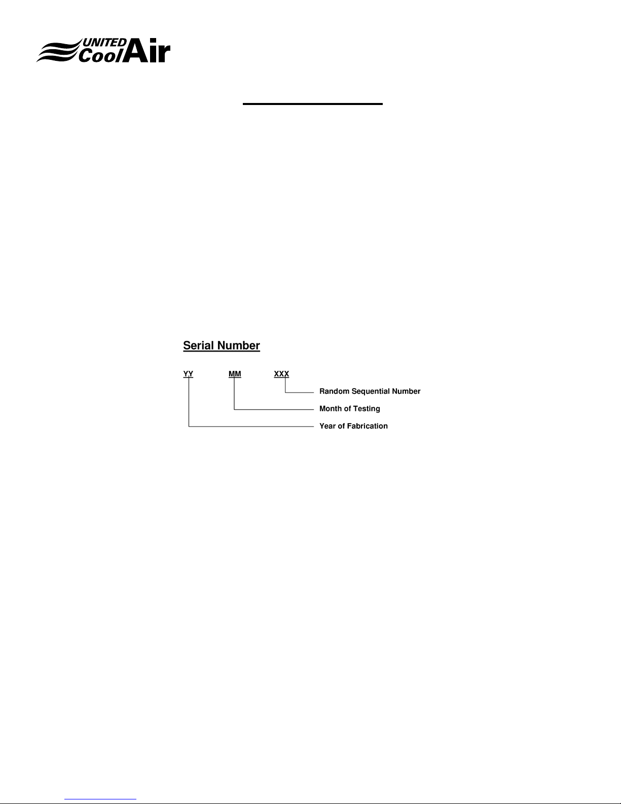
enter your serial number in the Serial Search eld and press return to retrieve your product-wiring diagram.
Your serial number is a combination of the year, month and sequential order of build date.
This action will return the Model number, Job Number and the wiring diagram for viewing as well as downloading.
NOTE: Only units shipped since November 2016 are available on the site, for older units please contact the factory directly
at 717-843-4311.
Subject to change without notice. 10.20-IM (0818)
4
Page 5
Installation, Operation and Maintenance Manual
Important Notice
This manual is the property of the owner�
Please be sure to leave it with the owner when you leave the job�
VariCool® VAV
NOTE: If the unit design was ordered specic to the
application or installation, please refer to the Addendum
at the end of this product literature� The unit may have
features or options specic to this job or application so
please refer to the addendum for details� The addendum
will also list the specic United CoolAir Job Number
or eld reference Job Name. Examples of unit design
specic to unit ordered will include product dimensions,
special control sequences and remote condenser /
condensing sections�
Use of Symbols
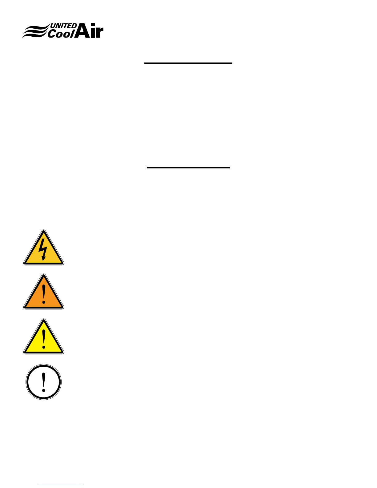
This publication includes warnings, cautions and information icons that point out safety related issues or conditions as well
as other pertinent information relative to a safe installation, service or maintenance situation. The following icons should be
interpreted as follows:
ELECTRICAL
HAZARD
WARNING
The electrical hazard icon indicates the presence of an electrical hazard which
could result in electrical shock or death.
The warning icon indicates a potentially hazardous situation which could result
in death or serious bodily injury if not avoided.
CAUTION
INFORMATION
Subject to change without notice. 10.20-IM (0818)
The caution icon indicates a potentially hazardous situation which may result in
minor or moderate injury if not avoided.
The information icon indicates a situation that may result in equipment or
property damage. The information provided alerts the reader to relevant facts
and/or conditions.
5
Page 6

Installation, Operation and Maintenance Manual
General Information
VariCool® VAV
VariCool units are cooling and optional heating systems
designed to effectively and efciently maintain tenant
occupied spaces within oor by oor building structures.
Each VariCool unit delivers continuous air ow at varied
air volumes and constant temperature to maintain tenant
occupied space settings through eld supplied VAV terminal
outlet boxes. Each unit is designed for optimal energy
efciency, reliability, IAQ, and lowered sound levels. Each
occupant then controls their specic zone by adjusting
temperature setting allowing the VAV terminal outlet box to
open to provide conditioned air. As the VAV box opens, the
VariCool automatically adjusts to maintain the systems static
pressure set point.
Multiple VariCool Systems may be networked together for
unit lead lag, back up/assist, and system rotation. Options
are available for linking each system through a facilities
Building Management System (BMS).
Each unit is shipped in two/three pieces (depends on model
size) for ease on movement to the location of installation.
EQUIPMENT INSPECTION
Upon receiving the unit, carefully inspect all sections for visible
or concealed interior/exterior damage. If damage occurred
during transit, contact the freight carrier immediately and le
a damage claim report. Inspect the unit data plate to verify
that the model unit that was ordered is the correct unit being
received. All accessory components for the application that
must be eld installed are shipped loose in one or several
boxes in the compressor section.
may be moved to the location of installation by crane, fork lift,
hand truck, or roller bars. Units are provided with lifting rings
for rigging and movement by crane. Spreader bars must be
used to protect section cabinet structure during movement.
Protection must be used so that damage to the cabinet
does not occur when using cables or slings. Be certain each
section is well supported when moving. When using dollies,
fork lifts, hand trucks, or roller bars, make sure the sections
base rails are well supported and the weight of the sections
are distributed evenly so that dropping or damage does not
occur during movement.
LOCATION AND CLEARANCES
The unit should be installed in an equipment room located
away from occupied tenant spaces. Careful consideration
should be taken during system layout and installation to allow
for minimum required service clearances for the VariCool
unit. Minimum clearances provided are worst case scenario.
If the clearances were less around the cooling coil section
and a cooling coil had to be replaced, it would be difcult to
maneuver the coil around the unit unless a service access
door(s) to the mechanical room were located next to the
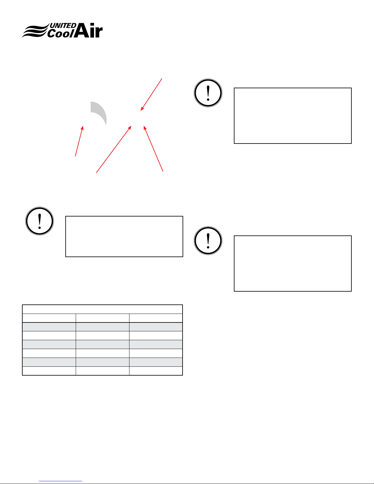
VariCool’s cooling coil end. Figure 1 – Service Clearances
and Table 1 show minimum clearance requirements for each
model unit. If the unit has an optional water side economizer
coil, the distance for service clearance must be maintained
from the edge of the lter rack which will mount onto the
economizer section on larger units but DX cooling coil
on smaller units as the economizer coil will be mounted
internally on smaller systems.
HANDLING
Use extreme caution so that damage does not occur when
moving each section to the location of installation. The unit
Subject to change without notice. 10.20-IM (0818)
6
Page 7
Installation, Operation and Maintenance Manual
VariCool® VAV
FIGURE 1 – Service Clearances
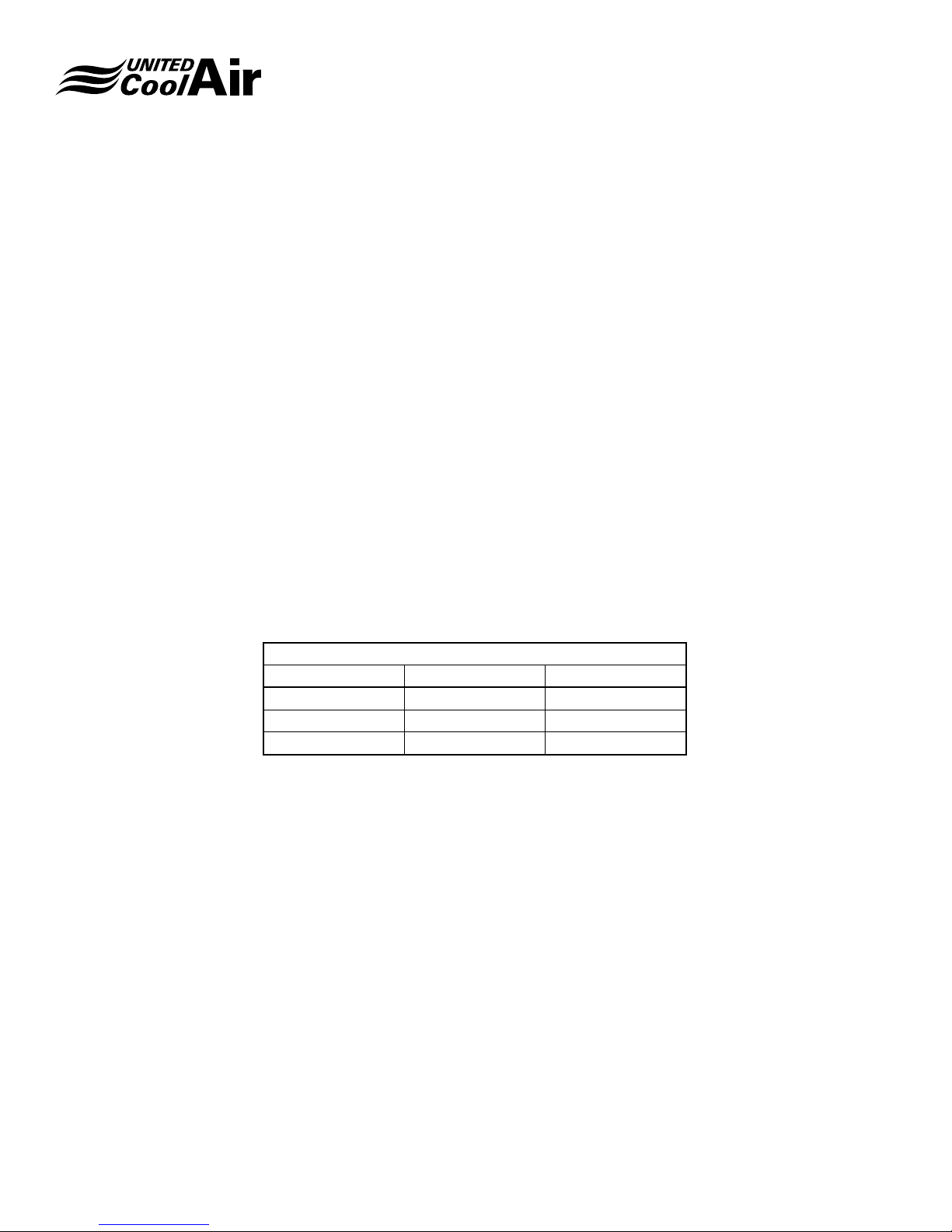
TABLE 1- SERVICE CLEARANCES
Unit Model (A) Dim (B) Dim
AV*8 – AV*16 30” 30”
AV*20-AV*30 42” 36”
AV*32-AV*60 50” 36”
UNIT DIMENSIONS
Figure 2 – Unit Dimensions and Table 2 show the dimensions
of each unit section. Note: If the System has the Water Side
Economizer Coil option, the unit will have a fourth section
that will be attached onto the Cooling Coil/Return Air Inlet
end of the unit. This has been labeled with the dimension
Tx on the diagram and it will vary depending on the lter
options desired.
Subject to change without notice. 10.20-IM (0818)
7
Page 8
Installation, Operation and Maintenance Manual
VariCool® VAV
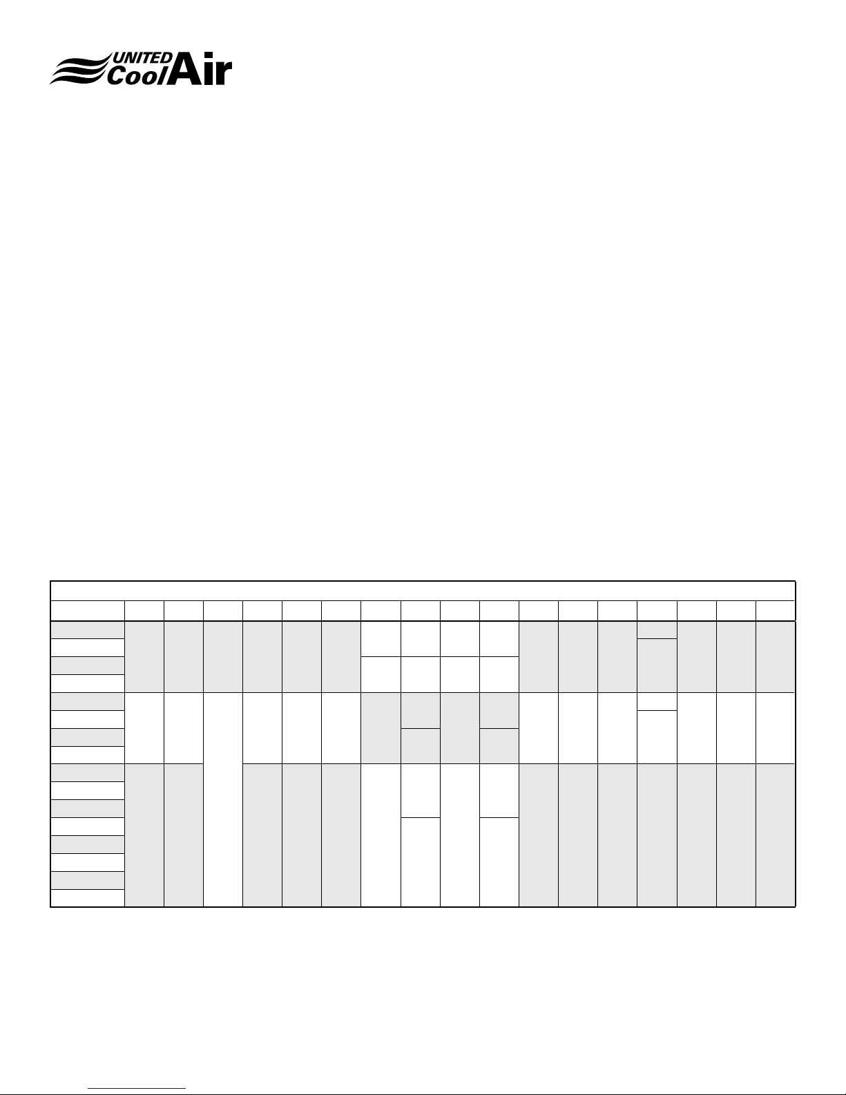
FIGURE 2 – Unit Dimensions
TABLE 2 – Unit Dimensions
MODEL A B C D E F G H I J K L M N P R S
AV*08
AV*10
AV*16
AV*20
AV*24
AV*30
68 68 32 32 38 30
80 80
35 48 32 20
16 26 8 21
18 32 7 18
36
7.5
44 18
AV*32
AV*36
AV*40
AV*44
AV*48
AV*52
35
98 100 52 62 36 30
42
11
52 24
AV*56
AV*60
Tx – Filter Rack dimensions are as follows:
T1 – 7” width when a standard 2” Filter is ordered
T2 – 9.5” width with extra ltration option includes a 2” plus 4” lter back to back
TBD TBD 21.5
22
TBD TBD 21
29
1.5 97 4 80 10.5 4.5 86
20
TBD 5 50
40AV*12
40
TBD 5 66
60AV*26
Subject to change without notice. 10.20-IM (0818)
8
Page 9
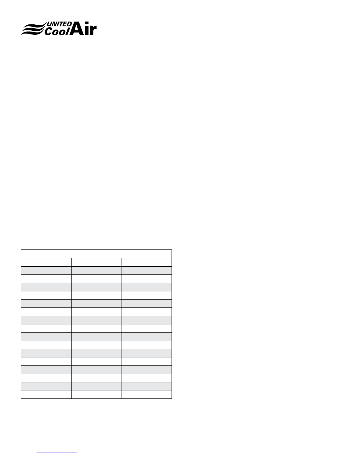
UNIT WEIGHT
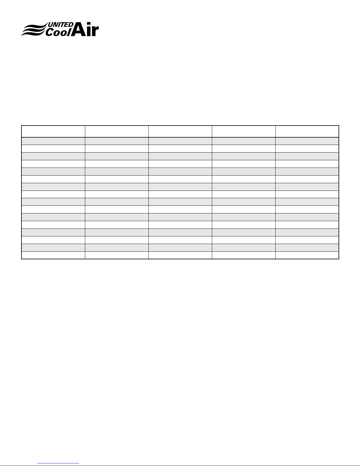
Table 3 – Unit Weight shows the weights of each model. The
weight of each unit is listed as a standard VariCool without
options. Table 4 – Optional Component Weight references
the weights of each optional component or upgrade package.
MODEL BLOWER (lbs) EVAPORATOR (lbs) CONDENSER (lbs) TOTAL (lbs)
AVW08 588 521 592 1701
AVW10 617 550 642 1809
AVW12 699 562 732 1993
AVW16 757 619 796 2172
AVW20 1134 856 910 2900
AVW24 1270 954 1046 3270
AVW26 1305 954 1196 3455
AVW30 1305 989 1216 3510
AVW32 1735 1256 1697 4688
AVW36 1787 1325 1673 4785
AVW40 1805 1387 1847 5039
AVW44 1953 1422 1899 5274
AVW48 1953 1479 1942 5374
AVW52 2087 1489 2227 5803
AVW56 2155 1535 2247 5937
AVW60 2155 1593 2287 6035
Installation, Operation and Maintenance Manual
VariCool® VAV
When calculating the weight for each unit, the weight of each
optional component must be added to the standard VariCool
unit weight shown in Table 3.
Table 3 – Unit Weight
Subject to change without notice. 10.20-IM (0818)
9
Page 10

Installation, Operation and Maintenance Manual
VariCool® VAV
UNIT INSTALLATION
Install the unit using the following procedures. Consideration
must be taken for proper condensate drain installation. Slight
elevation of the VariCool unit may be required for installation
of the condensate drain. Methods for elevating the VariCool
units are support rails, concrete pad(s), or spring isolators.
1� Once the unit’s sections have been moved to the
location of installation, locate the factory provided
mounting hardware, which has been pre-installed in the
holes where the sections will be connected together.
2� Using the appropriate size wrenches, remove the
mounting hardware and set in a safe location for
connecting the sections together during installation.
Vibration Absorbers
When installing the VariCool on a concrete pad, support
rails, or other methods other then spring isolation, use of
vibration absorbers is recommended to prevent transmission
of possible vibration.
3� Figure 3 – Vibration Pads shows the recommended
points for vibration absorbent pads (eld provided). We
recommend the use of a minimum 1” thick Neoprene
vibration absorbent pad under each point shown in
Figure 3. Models AV*09 through AV*16 only require the
pads under the corners only.
4� Place each vibration isolator into positions shown in
Figure 3, and then move the compressor and cooling
coil section into the location of installation being careful
not to damage the quick connect refrigerant piping.
5� Fasten the cooling coil section bottom half to the
compressor section using the mounting hardware
removed in Step 2.
6� Allow the hardware to remain only hand tight until the
Blower Section is installed.
INFORMATION
IMPORTANT: Before proceeding with
the installation of the Supply Air Blower
Section, we recommend connecting the
refrigerant quick connect connections
otherwise it may be difcult to make the
connections.
Refrigerant Connections
The DX Cooling Coil section refrigerant circuit is connected
to the compressor/condenser section using quick-connect
refrigerant connections. If the VariCool unit is a split system
with a Remote Air Cooled Condenser, refer to the section on
Split Systems. If the VariCool was ordered as a packaged
system, connecting refrigerant tubing will be fairly simple.
The quick connect ttings are self-sealing so they do not
permit refrigerant ow until they are completely tight. Follow
these steps for a packaged system:
7� Remove the caps on the quick connect refrigerant
lines.
8� Using a small amount of National 150 or 3G brand
refrigerant oil, lightly lubricate the threads of the
quick connect ttings. (5 to 6 droplets of oil are
recommended)
9� Align each quick connect tting and hand thread the
Female Quick Connect ttings onto the Male Quick
Connect ttings as shown in Figure 4 – Quick Connect.
FIGURE 3 – Vibration Pads
Subject to change without notice. 10.20-IM (0818)
10
Page 11
Installation, Operation and Maintenance Manual
VariCool® VAV
Female Fitting
Clockwise Rotation
Apply oil to male threads
Male Fitting
FIGURE 4 – Quick Connect
INFORMATION
NOTE: Be certain to count the number
of complete thread rotations. Observe
the number of turns reference Table 6 to
determine how tight to make the quick
connect couplings
10� Continue to hand thread until slight resistance is
observed.
11� Once slight resistance is evident, continue to tighten
the ttings using appropriate size wrenches listed in
Table 5.
TABLE 5
QC-Size Wrench # Full Turns
3/8” 1-3/16” 6
1/2” 1-3/16” 6
5/8” 1-5/8” 7-3/4
3/4” 1-5/8” 7-3/4
7/8” 1-5/8” 8
1-1/8” 2” 8
12� If the quick connect still feels loose, tighten just a bit
more until complete resistance is evident.
INFORMATION
NOTE: Once tight, refrigerant should be
able to pass through the quick connect
couplings. If problems with low refrigerant
pressure appear during system startup,
double check the tightness of these quick
connect couplings as loose ttings will
restrain full refrigerant ow.
13� Move the Blower Section into position of installation
making sure the side that the blower can be seen will
mate up with the large opening in the Cooling Coil
Section.
14� Lift the blower section up onto the Compressor Section.
15� Use the remaining mounting hardware to connect the
Blower Section to the Cooling Coil Section.
16� Using the appropriate size wrenches, hand-tighten all
mounting hardware.
INFORMATION
Note: seismic isolators are shipped
completely locked into position. Once
the blower section is installed the spring
isolators adjusted to loosen the blower on
isolators. The blower should be allowed to
oat on the isolators approximately ½" to
1" side to side and back and fourth.
17� Once the supply air blower is installed, the spring
isolators under the supply air blower must be
loosened. It is the responsibility of the installing
contractor to loosen the spring isolators. These
isolators are tightened for shipping purposes only.
They must be loosened for proper operation.
Subject to change without notice. 10.20-IM (0818)
11
Page 12
Installation, Operation and Maintenance Manual
VariCool® VAV
Duct Connections
A supply air plenum must be eld fabricated and attached
to the supply air outlet with a exible duct collar. Follow
appropriate guidelines for typical ducting installation.
Provide a duct length that is 3 to 4 times the diameter of
the plug fan wheel before making the rst transition. Provide
turning vanes when required. Attach the supply air plenum
Water Piping / Water Flow
As a standard, units shall have a shell and tube water cooled
condenser. The end plates of the shell and tube condenser
are fully removable for brush cleaning when soft deposits or
scale have formed internal to the condenser coil. Table 6 lists
the water ow and water pressure drops for each model unit.
Tube and tube water cooled condensers may be substituted.
Water Connections
Do not reduce water inlet and outlet connections as this will
restrain water ow and increase water pressure. The inlet
water line should have a strainer accessible for periodic
cleaning. Both the inlet and outlet water lines should have
eld installed water shut-off valves (Gate or Ball type valves).
The shutoff valves are required for maintenance, system
repairs, or long periods of system shut down.
TABLE 6 – Flow Rates/PSI Drop
Model GPM PSI
AVW8 24 4
AVW10 30 6
AVW12 36 7
AVW16 48 8
AVW20 60 6
AVW24 72 8
AVW26 78 10
AVW30 90 14
AVW32 96 8
AVW36 108 10
AVW40 120 6
AVW44 132 7
AVW48 144 8
AVW52 162 10
AVW56 168 12
AVW60 180 14
Recommended Field Installed
Externally
Condensate Drain Connection
Each VariCool unit has a condensate drain connection on
the Cooling Coil section. For systems with the Water Side
Economizer coil option, condensate drain connections are
provided
A condensate drain trap must be eld fabricated and
installed onto the 1" IPS drain connection. Each trap must
then be piped to a common waste drain. Refer to Figure
5 – Condensate Trap for reference dimensions. Units are
equipped with a 1" male IPS connection.
For systems with the Water Side Economizer coil option,
each individual section (Cooling Coil and Water Side
Economizer sections) must be piped individually with a
separate drain trap. Once each section has a drain trap, they
may be connected together by a tee and piped to a common
waste drain.
The depth of the condensate trap will vary due to the model of
the unit ordered and eld requirements. The purpose of the
trap is to neutralize the negative pressure created within the
blower cabinet. Refer to the order specications for external
static pressure (ESP) to calculate the depth required for the
“A” Dimension shown in Figure 5. The A Dimension must
equal or exceed the negative pressure developed by the
supply air blower. If it does not, the condensate will not drain
properly and may allow the drain pan to overow. The lower
leg of the trap must maintain a minimum depth of 3-1/2” to
maintain a water seal on during all operating conditions.
Plug each section’s (Cooling Coil and optional Water Side
Econo Coil) opposite side drain connection as shown.
Subject to change without notice. 10.20-IM (0818)
12
Page 13
FIGURE 5 – CONDENSATE TRAP
ELECTRICAL CONNECTIONS
All electrical wiring must be in accordance with NEC (National
Electrical Code) and state and local building codes. Refer to
the specications section or the unit’s data tag for the unit’s
power requirements. The main power entrance for each
VariCool unit is located directly above the electrical box.
SINGLE POINT DISCONNECT (OPTION)
If the VariCool unit has through the door single point power
disconnect option, turn the disconnect switch to the ON
position.
SERVICE DISCONNECT
A eld installed fused single point power service disconnect
is required. Install the service disconnect in accordance
with NEC, State, and Local building codes. NEC guidelines
require the unit’s disconnect be installed within sight of the
unit.
A factory provided power block is installed internal to the
VariCool’s electrical control panel. Route the main power
wires in accordance with electrical codes to the eld provided
unit disconnect and terminate them on the line side of the
disconnect. Route the power wires from the Load side of
the eld provided service disconnect to the unit power block
inside the electrical panel.
A ground termination point is located within the VariCool’s
electrical control panel.
Installation, Operation and Maintenance Manual
VariCool® VAV
INFORMATION
NOTE: Conduit is not an acceptable
ground source. A separate ground conduct
must be connected from Earth Ground to
the factory supplied ground lug internal to
the unit.
SENSOR FIELD MOUNTING & WIRING
All sensors and optional components that must be eld
installed and wired to the electrical control panel must be
wired as shown on the electrical diagram provided with the
unit and the instructions listed below.
Static Pressure Transducer
The static pressure transducer is factory installed internal to
the main electrical panel and wired back to the main control
board. Pneumatic tubing (eld supplied) must be connected
from the “HIGH” connection to a point approximately 2/3rds
the distance down the straightest length of supply air ducting.
NOTE: Make certain there are no kinks in the pneumatic
tubing.
1� Drill a hole into the ducting at a right angle. Place
approximately 1/8” of the high pressure tube into the
duct at a right angle. The end of the pneumatic tubing
must be cut at and make a right angle for the tube to
pick up the correct air pressure reading.
2� Use a clamp to secure the tube to the ducting.
3� Make certain the end of the tube is cut ush at a 90
degree right angle. This tube must be located in
ambient air.
The static pressure transducer is preset to read from 0”
to 2.5” W.C. The VariCool’s controller will read the preset
conguration. If a lower pressure conguration is desired,
use the manufacturer’s provided literature to re-congure for
the sensor to read the desired lower pressure setting.
INFORMATION
NOTE: The VariCool’s controller for sensor
calibration must also be readjusted. This
is explained under sensor calibration in
the Marvel Plus controller section.
Subject to change without notice. 10.20-IM (0818)
13
Page 14

Installation, Operation and Maintenance Manual
VariCool® VAV
Supply Air Temperature Sensor
The supply air temperature sensor is typically factory
installed. If the sensor is factory installed, it will be connected
to terminal strip TB2 terminals 3 and 4. It will have a
label around the sensor wire stating “SUPPLY SENSOR
FACTORY INSTALLED”.
In some cases, the sensor must be eld installed in the
straightest length of supply air duct for uniform air ow. The
location of the sensor must be relatively close to the duct
pressure transducer but must not impede the airow to the
inlet of the transducer. A few feet from the transducer is
recommended.
1� Cut out the mounting template provided with the
sensor.
2� Select the location to mount the sensor and drill a hole
through the supply air duct at least ¾” in diameter.
3� Using a 7/64” drill bit; drill the three fastening screw
holes located on the template for the fastening ring.
4� Remove the duct sensor’s mounting ring from the duct
probe and position it over the holes previously drilled in
the duct.
5� Use three #6 x ¾” Pan Head sheet metal screws and
fasten bracket to the duct.
6� Place the probe into the supply air duct.
7� Use the screw provided to tighten the clamping ring.
Using a minimum 18-20 AWG 300 volt rated two conductor
shielded cable with drain wire make the following electrical
connections.
8� The supply air temperature sensor is non-polarity
observant. Connect from one NTC terminal inside the
supply air temperature sensor to TB2-3.
9� Connect the other NTC terminal inside the temperature
sensor to TB2-4.
10� Connect the drain wire to ground at the VariCool’s
electrical control panel end only.
Airside Economizer option or optional Humidication/
Dehumidication, a Humidity Sensor will also be provided.
The unit Return Air Sensor must be eld installed in the return
air ducting, Return Air Plenum, Open Return Air Plenum as
close to the VariCool unit’s Filter Rack as possible. Since
United CoolAir may not know the application, please specify
the type of sensor (wall or duct mount) required for eld
installation. Typically if the return air is Open Plenum, a wall
mount sensor is recommended. If the return air is ducted
into the unit, a duct mount sensor is recommended.
BE AWARE: If the unit has optional humidity control,
polarity must be observed when making
electrical connections�
1� Cut out the mounting template provided with the
sensor.
Duct Mount Installation
2� Select the location to mount the sensor and drill a hole
through the supply air duct at least ¾” in diameter.
3� Using a 7/64” drill bit; drill the three fastening screw
holes located on the template for the fastening ring.
4� Remove the duct sensor’s mounting ring from the duct
probe and position it over the holes previously drilled in
the duct.
5� Use three #6 x ¾” Pan Head sheet metal screws and
fasten bracket to the duct.
6� Place the probe into the supply air duct.
7� Use the screw provided to tighten the clamping ring.
Wall Mount Installation
If mounting directly to drywall, use the enclosed template
and the screws and wall anchors enclosed with the sensor.
A switch box may also be used. A three position switch box
is recommended but a single position switch box rotated
90 degrees and mounted to a rigid surface will also sufce.
Return Air Temperature Sensor (Option)
The Return Air Temperature Sensor is provided for units
with the Morning Warmup option. If the unit has the
Subject to change without notice. 10.20-IM (0818)
14
Page 15

Installation, Operation and Maintenance Manual
VariCool® VAV
Return Air Sensor Wiring
Using a minimum 18-20 AWG 300 volt rated two conductor
shielded cable with drain wire make the following electrical
connections.
Note: Use a minimum two conductor cable for temperature
only. Use a minimum ve conductor for the temperature and
humidity sensor.
8� The supply air temperature sensor is non-polarity
observant. Connect from one NTC terminal inside the
supply air temperature sensor to TB3-NTC.
9� Connect the other NTC terminal inside the temperature
sensor to TB3-NTC.
10� Connect the drain wire to ground at the VariCool’s
electrical control panel end only.
Return Air RH Sensor (Option)
If the Return Air Sensor has the Humidity Sensor for optional
humidity control or Airside Economizer, continue with steps
11, 12, and 13.
11� Connect the terminal marked G+ to terminal TB3-G+.
12� Connect the terminal marked TB3- M to M.
13� Connect terminal Hout to terminal TB3-Hout.
Outdoor Air Sensor (Option)
The outdoor air temperature and humidity sensor is required
for Airside Economizer function. An outdoor air temperature
sensor is required for the Heat Pump option. The unit
Outdoor Air Sensor must be eld installed in the outdoor air
ducting.
BE AWARE: If the unit has optional humidity sensor
because of the Airside Economizer control,
polarity must be observed when making
electrical connections�
14� Cut out the mounting template provided with the
sensor.
Duct Mount Installation
15� Select the location to mount the sensor and drill a hole
through the supply air duct at least ¾” in diameter.
16� Using a 7/64” drill bit; drill the three fastening screw
holes located on the template for the fastening ring.
17� Remove the duct sensor’s mounting ring from the duct
probe and position it over the holes previously drilled in
the duct.
18� Use three #6 x ¾” Pan Head sheet metal screws and
fasten bracket to the duct.
19� Place the probe into the supply air duct.
20� Use the screw provided to tighten the clamping ring.
Outdoor Air Sensor Wiring
Using a minimum 18-20 AWG 300 volt rated two conductor
shielded cable with drain wire make the following electrical
connections.
Note: Use a minimum two conductor cable for temperature
only. Use a minimum ve conductor for the temperature and
humidity sensor.
21� The supply air temperature sensor is non-polarity
observant. Connect from one NTC terminal inside the
supply air temperature sensor to TB4-NTC.
22� Connect the other NTC terminal inside the temperature
sensor to TB4-NTC.
23� Connect the drain wire to ground at the VariCool’s
electrical control panel end only.
Return Air RH Sensor (Option)
If the Return Air Sensor has the Humidity Sensor for optional
humidity control or Airside Economizer, continue with steps
24, 25, and 26.
24� Connect the terminal marked G+ to terminal TB4-G+.
25� Connect the terminal marked TB4- M to M.
26� Connect terminal Hout to terminal TB4-Hout.
High Static Pressure Switch
The high static pressure switch is factory installed in the
electrical control box. This switch is factory wired into the
electrical controls for alarm if a high duct pressure condition
occurs. Pneumatic tubing must be eld installed from this
switch to a location ½ to 2/3rds the distance down the
straightest length of the supply air duct.
INFORMATION
Make certain there are no kinks in the
pneumatic tubing.
Subject to change without notice. 10.20-IM (0818)
15
Page 16

Installation, Operation and Maintenance Manual
VariCool® VAV
1� Drill a hole large enough to insert the pneumatic tubing
into the ducting at a 90 degree right angle.
2� Place approximately 1/8” of the high pressure tube into
the duct at the 90 degree right angle. The end of the
pneumatic tubing must be cut at and make a right
angle for the tube to pick up the correct air pressure
reading.
3� Use a clamp to secure the tube to the ducting and
route it back to the high static pressure switch.
4� Place the other end of this tubing onto the high
pressure end of the switch.
5� Install a second tube onto the low pressure side of the
pressure switch and route it to a room neutral pressure
location.
6� Again, make certain the end of the tube is cut ush at
a 90 degree right angle. This tube must be located in
ambient air.
Remote Alarm Output (Option)
A dry contact closure on alarm option may be provided
upon request. During an alarm condition, the Remote Alarm
output can be used to energize a eld provided and installed
alarm indicator light or buzzer.
If the system has this option, wire the electrical hot or
common side of the device being energized into terminals
TB2- 9 and TB2-10. The control circuit voltage must be 24
VAC and less than 1 amp inductive.
Remote Water Pump (Option)
If the system has the Remote Water Pump ON/OFF control
option, the hot or common side of the water pump’s starter
must be wired to terminals TB2-7 and TB2-8. The control
circuit voltage must be less than 250 VAC and not exceed
10 amps inductive loading.
O/A Damper Control (Option)
If the system has the Optional Outdoor Air Damper control,
the control signal to drive the eld provided damper actuator
must be wired through the factory provided terminals TB2-11
and TB2-12. The control circuit voltage must be 24 VAC and
not exceed1 amp inductive loading.
Smoke Detector/Fire Stat (Option)
If Smoke Detector or Fire Stat shutdown option is required,
a voltage free dry normally closed contact opens on alarm
must be eld provided from the device and wired back to the
VariCool’s Control Panel. Terminate from the device contact
termination points to the factory provided terminals TB2-18
and TB2-19.
Remote On/Off Control (Option)
With the Remote On/Off Control option, the unit will start
when a voltage free dry contact closure is provided to
Terminals TB2-20 and TB2-21. This closure may be provided
by a eld provided building management system or switch.
SEQUENCE OF OPERATION
DANGER: Be aware that fast moving fan drives and high
horsepower blowers/motors can cause injuries. Before
applying power to the VariCool unit, make sure all service
access doors are closed and latched to prevent injuries from
doors from blowing open or fast moving drives. Connect
power to the unit at the main power supply. Next, apply
power at the eld installed service disconnect switch and/
or optional factory supplied single point power disconnect.
MARVEL PLUS CONTROLLER
The VariCool system is designed to operate using a double
microprocessor design control system called a Marvel Plus.
The Marvel Plus control system incorporates a Marvel Plus
Main Board Control and a Marvel Plus Wall Mount Control
and display.
The Marvel Plus Main Board microprocessor is a 16 bit
microprocessor programmable controller with onboard
ash memory (6 Megabytes) to ensure better performance.
An onboard real time clock card allows for setting up of
occupancy schedules and recording of alarm occurrence for
storing of alarm history. Each Marvel Plus has the ability to
record up to 36 alarms/faults under an alarm history page to
allow technicians to view alarm history and temperatures
when the alarm occurred. Marvel Plus Main Boards allow
for connection some of the more widely used Building
Management Systems without requiring a Gateway to
interface.
The Marvel Plus Wall Controller is a terminal unit used to
interface with the Marvel Plus Main Board Controller through
the onboard display and keypad. The software stored in the
ash memory of the Marvel Plus Main Board was designed
with menu driven pages allowing customers to easily
navigate through the menus and submenus for setup of their
systems.
Note: See Our Marvel manual for operating instructions�
http://www.unitedcoolair.com/user-les/le/controls/
Marjiom.pdf
Subject to change without notice. 10.20-IM (0818)
16
Page 17

Installation, Operation and Maintenance Manual
Maintenance Procedures
VariCool® VAV
ELECTRICAL HAZARD
Turn OFF power and lockout service
before conducting any maintenance. Keep
hands, clothing and tools clear of electrical
terminals.
WARNING
Make sure to keep hands and clothing
clear of any moving belts, blowers and
motors while performing any maintenance.
Failure to do so could result in death or
serious bodily injury.
CAUTION
Any maintenance should be conducted
by qualied HVAC service personnel only.
Potentially hazardous situations which
may result in personal injury, equipment or
property damage.
Filters
Do NOT run unit without lters.
Throwaway lters are supplied which are pleated extended
surface type. Filters should be checked monthly for dirt
accumulation and changed when necessary. Replacement
lters must be the same type as originally supplied.
INFORMATION
Unit must be shut off at the disconnect
switch before the lters are serviced. Be
sure to check that the air ow direction
arrows on the lters point in the correct
direction of air ow.
Cleaning The Water-Cooled
Condenser
Any uid that is used to carry the heat away through the
condenser contains, minerals, dust from a cooling tower or
other foreign materials. Over time these contaminants will
build up on the walls of the heat exchanger.
This scale or fouling will result in a reduction in water ow,
less water temperature difference between inlet and outlet,
high condensing temperature and higher uid pressure drop.
All of these affect the operating performance and efciency
of the system and need to be addressed.
Cleaning a water-cooled condenser helps to improve the
heat transfer rate, reduce operational cost, restore efciency,
prolong heat exchanger life and reduce pressure drop
pumping costs. Deposits from water or water treatments,
such as scale, lime, rust or mud are removed.
Each installation is unique. Therefore, the uid quality and
operating conditions will dictate when the heat exchanger
needs to be cleaned.
During the start-up process record the water pressure drop
across the heat exchanger. Also record the inlet and outlet
water temperatures. After a period of time these values can
be checked to see how much loss of operating performance
has occurred. If a 10% or greater change has occurred, it
would be benecial to clean the heat exchanger.
There are a number of commercially available products for
cleaning a heat exchanger. Follow all industry practices to
safely and effectively clean the heat exchanger.
Blowers
Disconnect power and lockout the service before doing any
service or maintenance.
Air-cooled units are provided with adjustable belt drive
blower packages for both the evaporator and condensing
sections. Check that the blower wheel is tight on the shaft
and does not contact the housing. Bearings are permanently
sealed, but should be checked periodically for signs of wear.
Check for restrictions or foreign material in the air circuit.
The drive may be adjusted for different static pressures. If
such an adjustment is made, check that the motor current
draw does not exceed the motor nameplate current by more
than 10%.
Blower Motors
All blower motors are equipped with thermal overload
protectors.
WARNING
Open disconnects to unit before doing
any service or maintenance. A motor that
is off on thermal overload can start any
time when the automatic thermal overload
resets.
Subject to change without notice. 10.20-IM (0818)
17
Page 18

Installation, Operation and Maintenance Manual
VariCool® VAV
Blower Speed Adjustment
Blower speed may be changed by adjusting the variable
diameter sheave provided on the blower drive motor.
Sheave may be adjusted by removing the belt and loosening
the setscrew located in the hub of the outer ange. With the
setscrew loosened, the ange may be turned clockwise
to increase blower speed or counter-clockwise to reduce
blower speed.
Typically the motor and drive packages have been sized and
designed for the specic CFM and external static pressure
(ESP) of the application. Before making any changes conrm
what the performance was designed for and what the actual
performance is.
INFORMATION
Setscrew must be positioned directly
above the at section of the threaded
sheave shaft before tightening to hold
adjustment.
INFORMATION
Reduction of airow through excessive
external air friction losses, lowered blower
speed operation with dirty lters, or
obstructed air ow may result in excessive
condensation at air outlets, short cycling,
or total unit shut- down due to evaporator
coil icing.
INFORMATION
Verify that the motor current draw does
not exceed the motor nameplate current
by more than 10%.
Blower Bearing Lubrication
INFORMATION
Unit must be shut off at the disconnect
switch before the blowers are serviced.
Bearings on the smaller units are permanently sealed, but
should be checked periodically for signs of wear.
Larger units have pillow block bearings. Bearings will need
to be lubricated based on the use of the equipment.
Duty Grease Interval
Low Usage 12 Months
Periodic 6 Months
Continuous 1 – 2 Months
Use a high quality lithium grease for blower pillow block
bearings. Wipe off the “Zerk” tting with a rag before adding
grease so as not to introduce dirt into the bearing.
Slowly rotate the shaft while pumping it in. Pump the grease
in slowly so as not to blow out the bearing seal. When the
grease starts to “seep” out of the bearing you have put in
enough new lubricant.
Over lubricating can cause a bearing to fail from overheating
or it can blow out the seal.
Both excessive or inadequate grease may cause premature
failure. Provided there is some grease in the bearings for
lubrication, under lubrication is better than over lubrication
as grease can easily be added but not removed. Always
allow a slight bead around the circumference of the seals to
protect the bearing from foreign matter and helps ush out
the bearing as well.
Wipe off the “Zerk” tting with a rag after adding grease
Belts
Excessive belt tension is the number one cause for blower
bearing failure. Proper belt tension and pulley alignment are
essential for trouble free operation.
Deection is the amount the belt gives when force is applied,
usually by nger, to the belt at the approximate center point
to the belt span.
Insufcient deection indicates that the belt tension is
entirely too tight, and if not loosened somewhat, noise due
to excessive vibration, premature bearing failure, shortened
belt life, and a reduction in supply air blower performance
may result. Tight belts may also overload the motor and
cause the efciency to drop considerably or even premature
motor failure as well.
Excessive deection is an indication that the belt is not tight
enough. If not corrected, slippage may occur causing loss of
blower speed and belt failure. The belts will glaze then crack
or even break due to increased temperatures caused by
slippage. Belts may slip during start-up, but slipping should
stop as soon as the fan reaches full speed.
If the midpoint (midway between the blower and motor shaft)
of the belt is pressed inward, there should be about 1/2” to a
1” of deection when the belt is properly tensioned.
Subject to change without notice. 10.20-IM (0818)
18
Page 19

Installation, Operation and Maintenance Manual
VariCool® VAV
Refer to Figure 10 – Belt Tensioning below.
Deection Point
Belt Span
Figure 10 – Belt Tensioning
For proper tensioning, an excellent method to use is listed in
the following equation.
Deection = Belt Span
Belt span is in inches from center pulley to center pulley (see
Figure 10).
Belt tension is adjusted by using the adjusting bolt on the
end of the motor mounting frame.
Check the alignment of the sheaves to make sure that the
sheave faces are in the same plane. Check this by placing
a straight edge across the face of the sheaves. Any gap
between the edge and sheave faces indicates misalignment
64
If the color of this indicator is blue, the refrigerant is okay.
When the indicator is pink or purple, an abnormal condition
exists, servicing is required.
INFORMATION
After installation and during equipment
start-up, the sight glass may appear pink
or purple. This occurs during prolonged
periods of non-operation and should turn
blue after several hours (up to 12) of
operation.
Evaporator And Air-Cooled
Condenser Coils
The nned coils in a unit should be checked at least every
six (6) months or more frequently based on experience of
the specic application.
Evaporator nned coils can become “fouled” due to a build
up of contaminants in the air path that are not caught or
captured in the air lters. Over time this build up on the n
surface can reduce heat transfer and increased resistance
to air ow. The end result might be higher operating costs or
occupant discomfort
A dirty condenser coil will cause high condensing pressures,
resulting in higher power consumption and possibly system
shut-down by high pressure safety control. A dirty evaporator
coil will reduce unit capacity and eventually will cause system
shut-down by the low pressure safety control.
Finned Coil Cleaning
Note: This alignment method is only valid when the width of
the surfaces between the belt edges is the same for
both sheaves� When they are not equal or when using
adjustable pitch pulleys, adjust so that the belts have
approximately equal tension� Both shafts should be
at right angles to the belt� Check the setscrew and/or
bushing bolt tightness�
Belts tend to stretch somewhat after installation. Recheck
belt tension after several hours of operation.
Refrigerant Systems
All refrigerant circuits contain a liquid line sight glass. If
bubbles appear in the sight glass, the system is either
undercharged with refrigerant or there may be a restriction in
the liquid line upstream of the sight glass. However, bubbles
will appear every now and then in units with the hot gas
bypass option. Bubbles will also appear upon compressor
start up, but normally clear to pure liquid after a few minutes
of operation.
The sight glass contains a moisture indicator which changes
color when moisture is present in the refrigerant circuit. This
indicator is the circular dot in the center of the sight glass.
Subject to change without notice. 10.20-IM (0818)
Before cleaning any nned coils, remove the lters. Remove
any large debris or visible dirt accumulation.
WARNING
Make sure to follow all safety precautions
when cleaning any coil with a commercially
available coil cleaner. Follow all
recommendations for safety clothing and
gear. Failure to follow all safety instructions
could result in death or serious injury.
CAUTION
Clean coils only with cold water and a
suitable detergent or a commercially
available coil cleaner. DO NOT use hot
water or steam to clean a coil containing
refrigerant as this may cause a high
pressure situation that could damage
the coil and associated safety devices or
refrigerant components.
19
Page 20

Installation, Operation and Maintenance Manual
VariCool® VAV
CAUTION
Conrm that any coil cleaning agents,
detergents or solutions are suitable for
use on a copper tube/aluminum n coil. If
the cleaning agent is to acidic or alkaline,
damage to the coil ns may result.
Rinse all coils thoroughly after any coil cleaning.
Use a suitable n comb after the coil cleaning to straighten
any bent ns.
Water Side Economizer Coil
If a unit contains the optional water side economizer coil it
may also require a periodic cleaning. These coils will need
to be cleaned using a chemical solution. These are available
commercially. Follow all manufacturer recommendations
and safety warnings.
Water Valves
At least once a quarter check the water vales to make sure
that no leaks are present. Look at the valve stem and all
piping joints.
If any leaks are found follow the manufacturers
recommendations for tightening any seals or replacing any
gaskets.
Hard Start Kit
A start assist device is utilized on all single phase units. The
purpose of this device is to assist the compressor in starting
under low voltage conditions.
A capacitor in conjunction with a Positive Temperature
Coefcient (PTC) relay is installed across the run and
start windings of the motor. The PTC device utilizes a
ceramic element with a predictable thermal response to
the introduction of electric current. When the compressor is
called upon to start, the start capacitor provides a voltage
boost to the start winding of the motor and causes the motor
to turn. As the starting current is introduced across the start
windings, the PTC element begins to warm. When the PTC
device reaches approximately 250° F (corresponding to 0.6
- 0.8 seconds), the resistance in the element increases and
creates an open switch that releases the start winding from
the circuit and the motor continues to run. If the compressor
does not start before the device heats to 250° F, it will not
start until the PTC device cycles through a cool-down period
(usually 2 - 3 minutes). A compressor off-cycle timer is
included in the electrical circuit for this purpose.
The time delay also helps the refrigerant system pressures
to equalize at the end of the run cycle. This helps the
compressor during the starting process in that it is not
attempting to start against a high discharge pressure.
INFORMATION
Verify that this timer is set for 3 or more
minutes.
Checking Hot Gas Bypass Valve
1� Connect a calibrated thermocouple lead to the outlet
line at the hot gas bypass valve. Tie wrap and insulate
the lead.
2� Connect a low pressure refrigerant gauge to the suction
line.
3� Connect a high pressure refrigerant gauge to the liquid
line.
4� Operate the air conditioner in the cooling mode until the
system is stabilized. (Approximately 15 minutes)
5� If the high side pressure is not at or above 400 psig,
block off the condenser inlet air stream until the
pressure is above this threshold. This will simulate
system performance level close to the design condition
of 95° F ambient.
6� The hot gas bypass valve setting is 104 psig.
A� If the suction pressure is 104 psig the
thermocouple reading should be approximately
117° F or higher. Please note that it may be
necessary to block off some of the evaporator air in
order to check this condition.
B� If the suction pressure is above 104 psig the
thermocouple reading should be less than 117° F.
C� If the suction pressure is below 104 psig the hot
gas bypass valve should be adjusted to raise the
pressure.
Adjustment Of Hot Gas Bypass Valve
The function of the hot gas bypass valve is to prevent the
suction pressure from falling below a predetermined set
point, thereby balancing the system. The set point is typically
104 psig (R-410a).
1� Connect a low pressure refrigerant gauge to the suction
line.
2� Operate the air conditioner in the cooling mode until
system is stabilized. (Approximately 15 minutes)
3� Remove the seal cap that covers the adjustment screw
of the hot gas bypass valve.
4� Adjust the valve by turning the stem. A CLOCKWISE
turn will increase the pressure setting. A
COUNTERCLOCKWISE turn will decrease the
pressure setting. One complete turn is equal to
approximately 4 psi change.
Subject to change without notice. 10.20-IM (0818)
20
Page 21

Installation, Operation and Maintenance Manual
VariCool® VAV
Adjustments should be made in small increments,
allowing the system to stabilize after each turn�
5� Vary the evaporator load to test at various conditions
that the suction pressure does not fall below the set
point (104 psig for R-410a).
6� Replace the seal cap on the hot gas bypass valve.
Sequence Of Operation Cooling - - Air-Cooled
The following sequence is based on the unit being controlled
by a suitable room thermostat. If another control type is being
utilized, reference the instructions for that device.
a� Raise thermostat set point to highest level.
b� Set System switch to “OFF” position.
c� Set Fan switch to the “AUTO” position.
d� Moving the Fan switch to the “ON” position should
cause the evaporator blower motor to run. Moving the
Fan switch back to “AUTO” should stop the blower.
e� Move the System switch to the “COOL” position.
Slowly lower the thermostat setting to call for cooling.
The evaporator blower should start (assuming the
Fan switch is set to “AUTO”) and the System lead
compressor should start. The condenser blower on an
air-cooled unit should start when the compressor is
activated.
f� On those units with multiple compressors, if the
thermostat set point continues to be lowered, the
second compressor should then start. Please note that
there may be a time delay between stages.
g� Set room thermostat at desired space temperature and
the Fan switch to “AUTO” or “ON”. The unit will cycle as
required to maintain conditions.
Cooling - - Water-Cooled
A water-cooled unit sequence will be the same as above,
except that air-cooled blower will be replaced by a pump or
valve being activated for water ow through the condenser.
Cooling - - Chilled Water
Chilled water unit sequence is the same as the above,
except that the compressor and condenser blower activation
is replaced by the chilled water valve function.
Heating (Other Than Heat Pump)
The following sequence is based on the unit being controlled
by a suitable room thermostat. If another control type is being
utilized, reference the instructions for that device.
a� Lower thermostat set point to lowest level.
b� Set System switch to “OFF” position.
c� Set Fan switch to the “AUTO” position.
d� Moving the Fan switch to the “ON” position should
cause the evaporator blower motor to run. Moving the
Fan switch back to “AUTO” should stop the blower.
e� Move the System switch to the “HEAT” position. Slowly
raise the thermostat setting to call for heating. The
evaporator blower should start (assuming the Fan
switch is set to “AUTO”) and the heat type (electric, hot
water or steam) should start.
f� On those units with multiple heat stages, if the
thermostat set point continues to be raised, the
additional heat stages should then start. Please note
that there may be a time delay between stages.
g� Set room thermostat at desired space temperature and
the Fan switch to “AUTO” or “ON”. The unit will cycle as
required to maintain conditions.
Heating (Heat Pump, Water Source)
The following sequence is based on the unit being controlled
by a suitable heat pump room thermostat. If another control
type is being utilized, reference the instructions for that
device.
a� Lower thermostat set point to lowest level.
b� Set System switch to “OFF” position.
c� Set Fan switch to the “AUTO” position.
d� Moving the Fan switch to the “ON” position should
cause the evaporator blower motor to run. Moving the
Fan switch back to “AUTO” should stop the blower.
e� Move the System switch to the “HEAT” position.
Slowly raise the thermostat setting to call for heating.
The evaporator blower should start (assuming the
Fan switch is set to “AUTO”) and the System lead
compressor should start. A pump or valve should also
be activated for water ow through the condenser.
f� On those units with multiple compressors, if the
thermostat set point continues to be raised, the
additional heat stages should then start. Please note
that there may be a time delay between stages.
g� Set room thermostat at desired space temperature and
the Fan switch to “AUTO” or “ON”. The unit will cycle as
required to maintain conditions.
Subject to change without notice. 10.20-IM (0818)
21
Page 22

Installation, Operation and Maintenance Manual
Troubleshooting
WARNING
Turn OFF power to unit before conducting any troubleshooting, unless the tests you are performing require
system operation. Keep hands, clothing and tools clear of electrical terminals and rotating components.
ITEM CODE PROBLEM PROBABLE CAUSE SOLUTION
1 Control is erratic.
2 Blower fails to start.
3 Compressor fails to start.
4 Compressor short cycles.
Wired improperly or connections are broken Check wiring connections against schematic
diagram.
Defective contactor
Overload tripped
Marvel alarm
Thermostat set too high
Complete loss of refrigerant charge
Head pressure too high
(high pressure switch open)
PTCR will keep compressor OFF
for 3 - 5 minutes
Low line voltage causing compressor to
overheat and trip on thermal overload
Drain pan switch open
Low line voltage causing compressor to
overheat
Dry or icy evaporator coil (reduced air ow)
Lack of refrigerant (bubbles in sight glass)
Short cycling of conditioned air
Repair or replace contactor.
Reset and check cause.
Clear alarm(s) after correcting problem.
Adjust to desired temperature.
Repair leak and recharge refrigerant system.
Check condenser for obstructions and remove.
Check for the required water ow through the water
regulating valve and the condenser coil. Manually
reset thermostat. With Marvel, turn off alarm and
reset.
Wait for PTCR to cool off. Compressor should start
in 3 - 5 minutes.
Stop unit and troubleshoot power supply and
compressor circuit for low voltage. Please note that
it may take the compressor an hour or more for the
thermal overload to reset itself.
Check if the unit is draining properly.
Check power source for cause of electric variation
of line voltage.
Defrost and clean coil and replace dirty lters.
Check for leak. Repair and recharge the system
Make sure that duct connections are proper for
return air and supply air and ensure that they do not
mix with each other.
VariCool® VAV
NOTE: For operating and troubleshooting instructions for Marvel Controller or
humidier, refer to specic operating instructions that accompany the unit.
Subject to change without notice. 10.20-IM (0818)
22
Page 23

Installation, Operation and Maintenance Manual
ITEM CODE PROBLEM PROBABLE CAUSE SOLUTION
Lack of proper air quantity
Check lters: Clean or replace if necessary. Check
for obstruction across coil. Check rotation of evaporator blower to ensure correct rotation of evaporator
blowers.
5 Evaporator coil ices.
Low return air temperature
Raise return air set point or check for short cycling
of supply air.
Low refrigerant charge
Check for leaks and repair and recharge the
system.
VariCool® VAV
6 Noisy compressor
7 System short of capacity
Expansion valve stuck in open position
(cold suction line)
Broken compressor valve (compressor
knocking)
Worn or scarred compressor bearings
Liquid slugging
Excessive head pressure
Flash gas in liquid line
(bubbles in sight glass)
Expansion valve stuck open or possibly
obstructed
Clogged lter drier
Ice or dirt on evaporator coil
Head pressure control valve not fully open
Condenser coil dirty
Ensure thermal expansion valve bulb is tight on
suction line. Con- rm that bulb is located properly
on suction line. Check operation and superheat.
Replace compressor.
Replace compressor.
System overcharged. Reclaim excess refrigerant
from the high side of the system
Reduce head pressure (see item 8 below).
Check for leaks. Repair and re- charge the system.
Check sub- cooling.
Replace Valve.
Replace with new lter-drier.
Defrost or clean evaporator coil or replace dirty
lter.
Make sure that the required GPM of water ows
through the condensing section
Clean condenser coil
Subject to change without notice. 10.20-IM (0818)
23
Page 24

Installation, Operation and Maintenance Manual
ITEM CODE PROBLEM PROBABLE CAUSE SOLUTION
Air or other non-condensable gas in system
Evacuate system and recharge. Install new
lter-drier.
Condenser air intake blocked
Overcharge of refrigerant
Clean away debris.
Reclaim excess from high pressure side of the
system.
8 Head pressure too high
Condenser fan not operating
Check power to motor and ensure correct rotation
of blower.
Condenser water not circulating
Condenser blower running backwards
Check water regulating valve and adjust
Check phase of incoming power to unit (3 ph units
only). Reverse any two incoming power supply
wires (except ground).
9 Head pressure too low See Item 3, 4, & 7 above Correct as indicated
Flash gas in liquid line (bubbles in sight
Repair leak and recharge.
glass) due to a leak.
10 Suction pressure too low
Obstructed expansion valve
Loss of uid within expansion valve bulb.
Clogged lter-drier
Ice or dirt on evaporator coil
Evaporator blower running backwards
Repair or replace valve.
Replace power head and valve.
Replace with new lter-drier.
Defrost and clean evaporator coil and replace lter.
Check phase of incoming power to unit (3 ph units
only). Reverse any two incoming power supply
wires (except ground).
VariCool® VAV
Thermostat set too low
Circuit breaker tripped or blown
Adjust thermostat to the desired temperature.
Check for electrical short. . Replace breaker if
defective.
11 Heater inoperative
Heater high limit switch open
Insufcient air across heater elements. Check for
obstructed or dirty lters.
Heat elements burned out
Check continuity with OHM meter. Replace heater
element.
12 Water carry over Excessive air through unit Reduce CFM to unit specications.
Subject to change without notice. 10.20-IM (0818)
24
Page 25

Installation, Operation and Maintenance Manual
ITEM CODE PROBLEM PROBABLE CAUSE SOLUTION
13
System short of capacity in
free cool (water coil) mode
Check for control wiring to the free cool
solenoid valve.
Low water ow rate
Check wiring diagram and rewire.
Check source of water ow.
VariCool® VAV
14
15
Condensate Pump does
not run
Condensate Pump runs with
no discharge
16 Lock out relay tripped
Check to see that power to the pump is
Locate and repair electrical connection problem.
present.
Float not able to move freely.
Dirt or algae not allowing oat to activate
Clean pump and oat.
Clean pump and oat.
pump.
Tubing blocked or kinked
Check valve blocked
Inpeller blocked
Tubing elevation or run exceeds head
Inspect, clean or straighten as necessary.
Clean check valve.
Remove debris from pump impeller.
Verify tubing run is within pump head limitations.
capability
High or low pressure condition exists Refer to items 8 & 10 above.
Manually turn off system at thermostat and then
back on to reset. Manually reset high pressure
switch if tripped.
Subject to change without notice. 10.20-IM (0818)
25
Page 26

Installation, Operation and Maintenance Manual
Limited Warranty
VariCool® VAV
Important Notice!
This Limited Warranty specically provides that all installation,
operation and repairs of product and parts covered under
this limited warranty must be made with authorized parts
and by a licensed HVAC service provider. The product(s)
must be properly installed, and maintained by a licensed
HVAC service provider in accordance with the installation,
operation, and maintenance instructions provided by United
CoolAir Corporation. Failure to conform to such specications
and/or instructions shall void this limited warranty. United
CoolAir may request written documentation showing the
proper preventative maintenance.
United CoolAir warrants this product to be free from defects
in factory workmanship and material under normal use and
service and will, at its option, repair or replace any parts that
prove to have such defects within a period of one (1) year
from the date of product installation. This warranty extends
only to the original consumer purchaser in accordance
with the then current Terms and Conditions and is nontransferable.
For this warranty to apply, the product must be installed
according to United CoolAir recommendations and
specications, and in accordance with all local, state,
national and provincial codes. The product must not be
moved from its original place of installation. The replacement
part assumes the unused portion of this warranty.
This limited warranty applies only to products installed in the
continental United States, Alaska, Hawaii and Canada.
Exclusions
This Limited Warranty does not cover any:
1� Shipping, labor or material charges.
2� Damages resulting from transportation, installation or
servicing.
3� Damages resulting from accident, abuse, re, ood,
alteration or acts of God.
4� Tampering with, altering, defacing or removing the
product serial number will serve to void this warranty.
5� Damages resulting from use of the product in a
corrosive atmosphere (such as concentrations of acids
or halogenated hydrocarbons).
6� Damages resulting from inadequacy or interruption of
electrical service, improper voltage conditions, blown
fuses, or other like circumstances.
7� Cleaning or replacement of lters or belts.
8� Damages resulting from failure to properly and
regularly clean air and/or water side of condenser and
evaporator.
9� Damages resulting from: (I) freezing of condenser
water or condensate; (II) use of corrosive water; (III)
fouling or restriction of the air/water circuit by foreign
material or like causes.
10� Damages resulting from operation with inadequate or
interrupted supply of air or water.
11� Damages resulting from use of components or
accessories not approved by United CoolAir.
12� This warranty does not apply to the installation,
plumbing and wiring not integral to the product.
13� Damages resulting from improper application or sizing
of unit.
This warranty is in lieu of all other warranties, expressed or
implied, including the implied warranties of merchantability
and tness for a particular purpose.
Some states (provinces) do not allow the disclaimer of
implied warranty, so that the above disclaimer may not apply
to you.
Some states (provinces) allow only a partial limitation on
implied warranties to limit the duration of implied warranties
to the duration of the express warranty. In such states
(provinces), the duration of implied warranties is hereby
expressly limited to the duration of the express warranty on
the face hereof.
In no event, whether as a result of breach of warranty or
contract, tort (including negligence) strict liability or otherwise,
shall United CoolAir be liable for special, incidental, or
consequential damages, including but not limited to loss
of use of the equipment or associated equipment, lost
revenues or prots, cost of substitute equipment or cost of
fuel or electricity. The above limitations shall inure to the
benet of United CoolAir’s suppliers and subcontractors.
The above limitation on consequential damages shall not
apply to injuries to persons in the case of consumer goods.
Some states (provinces) do not allow the exclusion or
limitation of liability for consequential damages, or for strict
liability in tort, so that the above exclusions and limitations
may not apply to you.
United CoolAir does not assume, or authorize any other
person to assume for United CoolAir, any other liability for
the sale of this product.
This warranty gives you specic legal rights. You may also
have other rights which vary from state to state (province to
province).
To obtain warranty service
Contact the installing or servicing contractor with the details
of the problem. Provide the model number, serial number
and date of installation. Warranty requests directed to the
factory will be referred back through the local distribution
network.
Model: ______________ Serial Number: _______________ Date of Installation: ________
Subject to change without notice. 10.20-IM (0818)
26
Page 27

Installation, Operation and Maintenance Manual
Limited Warranty for Hermetic Compressors
VariCool® VAV
United CoolAir warrants the hermetic compressor in this
product to be free from defects in factory workmanship and
material under normal use and service and will, at its option,
repair or replace the hermetic compressor if it proves to
have such defects within a period of ve (5) years from the
date of product installation. This warranty extends only to
the original consumer purchaser in accordance with the then
current Terms and Conditions and is non-transferable. If a
United CoolAir unit is matched with another manufacturers
unit the compressor warranty is limited to 1 year form the
date of product installation.
For this warranty to apply, the product must be installed
according to United CoolAir recommendations and
specications, and in accordance with all local, state,
national and provincial codes. The product must not be
moved from its original place of installation. The replacement
part assumes the unused portion of this warranty.
This limited warranty applies only to products installed in the
continental United States, Alaska, Hawaii and Canada.
Exclusions
This Limited Warranty does not cover any:
1� Shipping, labor or material charges.
2� Damages resulting from transportation, installation or
servicing.
3� Damages resulting from accident, abuse, re, ood,
alteration or acts of God.
4� Tampering with, altering, defacing or removing the
product serial number will serve to void this warranty.
5� Damages resulting from use of the product in a
corrosive atmosphere (such as concentrations of acids
or halogenated hydrocarbons).
6� Damages resulting from inadequacy or interruption of
electrical service, improper voltage conditions, blown
fuses, or other like circumstances.
7� Cleaning or replacement of lters or belts.
8� Damages resulting from failure to properly and
regularly clean air and/or water side of condenser and
evaporator.
9� Damages resulting from: (I) freezing of condenser
water or condensate; (II) use of corrosive water; (III)
fouling or restriction of the air/water circuit by foreign
material or like causes.
10� Damages resulting from operation with inadequate or
interrupted supply of air or water.
Model: ______________ Serial Number: _______________ Date of Installation: ________
11� Damages resulting from use of components or
accessories not approved by United CoolAir.
12� This warranty does not apply to the installation,
plumbing and wiring not integral to the product.
13� Damages resulting from improper application or sizing.
This warranty is in lieu of all other warranties, expressed or
implied, including the implied warranties of merchantability
and tness for a particular purpose.
Some states (provinces) do not allow the disclaimer of
implied warranty, so that the above disclaimer may not apply
to you.
Some states (provinces) allow only a partial limitation on
implied warranties to limit the duration of implied warranties
to the duration of the express warranty. In such states
(provinces), the duration of implied warranties is hereby
expressly limited to the duration of the express warranty on
the face hereof.
In no event, whether as a result of breach of warranty or
contract, tort (including negligence) strict liability or otherwise,
shall United CoolAir be liable for special, incidental, or
consequential damages, including but not limited to loss
of use of the equipment or associated equipment, lost
revenues or prots, cost of substitute equipment or cost of
fuel or electricity. The above limitations shall inure to the
benet of United CoolAir’s suppliers and subcontractors.
The above limitation on consequential damages shall not
apply to injuries to persons in the case of consumer goods.
Some states (provinces) do not allow the exclusion or
limitation of liability for consequential damages, or for strict
liability in tort, so that the above exclusions and limitations
may not apply to you.
United CoolAir does not assume, or authorize any other
person to assume for United CoolAir, any other liability for
the sale of this product.
This warranty gives you specic legal rights. You may also
have other rights which vary from state to state (province to
province).
To obtain warranty service
Contact the installing or servicing contractor with the details
of the problem. Provide the model number, serial number
and date of installation. Warranty requests directed to the
factory will be referred back through the local distribution
network.
Subject to change without notice. 10.20-IM (0818)
27
Page 28

Installation, Operation and Maintenance Manual
Limited Warranty Condensing Section
VariCool® VAV
United CoolAir warrants this product to be free from defects
in factory workmanship and material under normal use and
service and will, at its option, repair or replace any parts that
prove to have such defects within a period of one (1) year
from the date of product installation, to begin no later than
six (6) months after product shipment from the factory. This
warranty extends only to the original consumer purchaser in
accordance with the then current Terms and Conditions and
is non-transferable.
For this warranty to apply, the product must be installed
according to United CoolAir recommendations and
specications, and in accordance with all local, state,
national and provincial codes. The product must not be
moved from its original place of installation. The replacement
part assumes the unused portion of this warranty.
This limited warranty applies only to products installed in the
continental United States, Alaska, Hawaii, Puerto Rico and
Canada.
EXCLUSIONS
This Limited Warranty does not cover any:
1� Shipping, labor or material charges.
2� Damages resulting from transportation, installation or
servicing.
3� Damages resulting from accident, abuse, re, ood,
alteration or acts of God.
4� Tampering with, altering, defacing or removing the
product serial number will serve to void this warranty.
5� Damages resulting from use of the product in a
corrosive atmosphere (such as concentrations of acids
or halogenated hydrocarbons).
6� Damages resulting from inadequacy or interruption of
electrical service, improper voltage conditions, blown
fuses, or other like circumstances.
7� Cleaning or replacement of lters or belts.
8� Damages resulting from failure to properly and
regularly clean air and/or water side of condenser and
evaporator.
9� Damages resulting from: (I) freezing of condenser
water or condensate; (II) use of corrosive water; (III)
fouling or restriction of the air/water circuit by foreign
material or like causes.
10� Damages resulting from operation with inadequate or
interrupted supply of air or water.
11� Damages resulting from use of components or
accessories not approved by United CoolAir.
12� This warranty does not apply to the installation,
plumbing and wiring not integral to the product.
13� Damages resulting from improper application or sizing
of unit.
14� In the event that the refrigerant type is changed, as
a result of a compressor failure and the same type of
compressor is not available, any subsequent refrigerant
circuit component failures will not be covered under the
Limited Warranty.
This warranty is in lieu of all other warranties, expressed or
implied, including the implied warranties of merchantability
and tness for a particular purpose.
Some states (provinces) do not allow the disclaimer of
implied warranty, so that the above disclaimer may not apply
to you.
Some states (provinces) allow only a partial limitation on
implied warranties to limit the duration of implied warranties
to the duration of the express warranty. In such states
(provinces), the duration of implied warranties is hereby
expressly limited to the duration of the express warranty on
the face hereof.
In no event, whether as a result of breach of warranty or
contract, tort (including negligence) strict liability or otherwise,
shall United CoolAir be liable for special, incidental, or
consequential damages, including but not limited to loss
of use of the equipment or associated equipment, lost
revenues or prots, cost of substitute equipment or cost of
fuel or electricity. The above limitations shall inure to the
benet of United CoolAir’s suppliers and subcontractors.
The above limitation on consequential damages shall not
apply to injuries to persons in the case of consumer goods.
Some states (provinces) do not allow the exclusion or
limitation of liability for consequential damages, or for strict
liability in tort, so that the above exclusions and limitations
may not apply to you.
United CoolAir does not assume, or authorize any other
person to assume for United CoolAir, any other liability for
the sale of this product.
This warranty gives you specic legal rights. You may also
have other rights which vary from state to state (province to
province).
To obtain warranty service
Contact the installing or servicing contractor with the details
of the problem. Provide the model number, serial number
and date of installation. Warranty requests directed to the
factory will be referred back through the local distribution
network.
Continued on Next Page
Model: ______________ Serial Number: _______________ Date of Installation: ________
Subject to change without notice. 10.20-IM (0818)
28
Page 29

Installation, Operation and Maintenance Manual
Limited Warranty for Hermetic Compressors
VariCool® VAV
United CoolAir warrants the hermetic compressor in this
product to be free from defects in factory workmanship
and material under normal use and service and will, at its
option, repair or replace the hermetic compressor if it proves
to have such defects within a period of one (1) year from
the date of product installation, to begin no later than six
(6) months after product shipment from the factory. This
warranty extends only to the original consumer purchaser in
accordance with the then current Terms and Conditions and
is non-transferable.
For this warranty to apply, the product must be installed
according to United CoolAir recommendations and
specications, and in accordance with all local, state, national
and provincial codes. The product must not be moved from
its original place of installation. A second compressor failure
in the same refrigerant circuit is indicative of an application
issue and will not be covered under the Limited Warranty.
This limited warranty applies only to products installed in the
continental United States, Alaska, Hawaii, Puerto Rico and
Canada.
EXCLUSIONS
This Limited Warranty does not cover:
1� Shipping, labor or material charges.
2� Damages resulting from transportation, installation or
servicing.
3� Damages resulting from accident, abuse, re, ood,
alteration or acts of God.
4� Tampering with, altering, defacing or removing the
product serial number will serve to void this warranty.
5� Damages resulting from use of the product in a
corrosive atmosphere (such as concentrations of acids
or halogenated hydrocarbons).
6� Damages resulting from inadequacy or interruption of
electrical service, improper voltage conditions, blown
fuses, or other like circumstances.
7� Cleaning or replacement of lters or belts.
8� Damages resulting from failure to properly and
regularly clean air and/or water side of condenser and
evaporator.
9� Damages resulting from: (I) freezing of condenser
water or condensate; (II) use of corrosive water; (III)
fouling or restriction of the air/water circuit by foreign
material or like causes.
10� Damages resulting from operation with inadequate or
interrupted supply of air or water.
11� Damages resulting from use of components or
accessories not approved by United CoolAir.
Model: ______________ Serial Number: _______________ Date of Installation: ________
12� This warranty does not apply to the installation,
plumbing and wiring not integral to the product.
13� Damages resulting from improper application or sizing.
14� Discharge air temperature control, if not provided by
the factory, will void the compressor Limited Warranty.
15� In the event that the refrigerant type is changed, as
a result of a compressor failure and the same type
of compressor is not available, any subsequent
compressor failures will not be covered under the
Limited Warranty.
This warranty is in lieu of all other warranties, expressed or
implied, including the implied warranties of merchantability
and tness for a particular purpose.
Some states (provinces) do not allow the disclaimer of
implied warranty, so that the above disclaimer may not apply
to you.
Some states (provinces) allow only a partial limitation on
implied warranties to limit the duration of implied warranties
to the duration of the express warranty. In such states
(provinces), the duration of implied warranties is hereby
expressly limited to the duration of the express warranty on
the face hereof.
In no event, whether as a result of breach of warranty or
contract, tort (including negligence) strict liability or otherwise,
shall United CoolAir be liable for special, incidental, or
consequential damages, including but not limited to loss
of use of the equipment or associated equipment, lost
revenues or prots, cost of substitute equipment or cost of
fuel or electricity. The above limitations shall inure to the
benet of United CoolAir’s suppliers and subcontractors.
The above limitation on consequential damages shall not
apply to injuries to persons in the case of consumer goods.
Some states (provinces) do not allow the exclusion or
limitation of liability for consequential damages, or for strict
liability in tort, so that the above exclusions and limitations
may not apply to you.
United CoolAir does not assume, or authorize any other
person to assume for United CoolAir, any other liability for
the sale of this product.
This warranty gives you specic legal rights. You may also
have other rights which vary from state to state(province to
province).
To obtain warranty service
Contact the installing or servicing contractor with the details
of the problem. Provide the model number, serial number
and date of installation. Warranty requests directed to the
factory will be referred back through the local distribution
network.
Subject to change without notice. 10.20-IM (0818)
29
Page 30

Air-Cooled Unit
Start-Up Procedures (R-410a Systems)
Some of the numbered items below are referenced on the
Start Up Form that needs to be completed.
This procedure has been created based on utilizing a
standard wall thermostat. If another controller is being
utilized some of the steps below may need to be altered.
1� Start up must be performed by a qualied HVAC
Technician.
2� Make certain that all power is disconnected at the main
power circuit breaker or service disconnect before
starting any of this procedure.
3� Check all electrical screw terminals and wiring lugs
for tightness internal to the equipment. Components
may have loosened due to vibration during transit
or handling. Verify that the main power block lug
connections made in the eld are tight and secure.
4� Conrm that the voltage rating of the equipment data
tag coincides with the power that will be delivered to
the unit.
5� Verify that the circuit protection for the unit satises
Local and National Codes according to the unit data
tag Minimum Circuit Ampacity (MCA) and Maximum
Fuse Size (MFS).
6� Locate the unit thermostat and check all electrical
terminations against the unit electrical diagram and for
the unit thermostat.
Note: If using a digital thermostat with a “C” (Common)
terminal, this terminal MUST be terminated to the “C”
terminal in the unit� Failure to do so will result in the
thermostat shorting out and being destroyed�
7� Leak check the refrigerant system. While the unit was
leak checked at the factory, leaks can develop during
transit and / or handling.
8� Conrm that the unit condensate has been adequately
trapped and taken to a suitable point for disposal.
9� Verify that the lters are in place, clean and usable.
10� Switch the unit thermostat to the “OFF” position.
11� Apply power to the unit. Switch the circuit breaker or
eld supplied electrical service disconnect switch to the
on position.
Note: If the unit has the ooded condenser option the scroll
compressors will have crankcase heaters� If the
outdoor ambient is 70˚ F or lower, let the compressors
sit for approximately 24 hours before proceeding�
Installation, Operation and Maintenance Manual
VariCool® VAV
12� Record the voltage at the unit terminals.
13� If possible with the thermostat provided, switch the
evaporator blower to the RUN position. Verify that the
evaporator blower is activated.
14� Verify that the evaporator blower is rotating in the
correct direction (three phase units only).
Note: If the evaporator blower motor runs backwards,
shut off all power to the unit� Switch any two of the
incoming power leads at the unit terminal block�
The unit has been wired and phased properly at the
factory� DO NOT change any factory wiring to correct
for a phase problem�
Note: Before conducting the following start up sections
connect a suitable refrigerant gauge set to the unit
Schrader connections� Install temperature sensors to
record the appropriate refrigerant line temperatures�
Service gauge access ports have been provided in
the cabinet corner posts so that the gauge line hoses
can be run outside the cabinet with the access panels
installed�
15� Set the thermostat switch to a temperature set point
approximately 5˚ lower than the space temperature. Set
the thermostat fan switch to the AUTO position. Set the
thermostat operating mode to the COOL position. This
should energize the compressor(s) and both blowers.
Note: Dependent upon the options and/or the thermostat,
there may be a delay for the compressor(s) operation�
16� Verify that the condenser blower rotation is correct.
17� While waiting for the compressor(s) to stabilize,
record the External Static Pressure (ESP) for both the
evaporator and condenser blowers.
Note: Make sure all the unit access panels are in place when
taking these readings�
18� Record the return air temperature to the evaporator coil
along with the supply air temperature. (The unit should
have operated for at least 15 minutes before taking
these readings).
19� Record the outdoor ambient entering the condenser
coil along with the discharge air temperature of the
condensing section.
20� Record the suction line pressure and the suction line
temperature for each circuit near the compressor.
Continued on next page
Subject to change without notice. 10.20-IM (0818)
30
Page 31

Start-Up Procedures (R-410a Systems) Continued:
21� Using an appropriate pressure / temperature chart for
R-410a refrigerant, look up and record the saturation
temperature corresponding to the suction pressure.
22� Calculate and record the suction superheat for each
circuit by taking the difference between the suction
line temperature and the saturation temperature
corresponding to the suction pressure.
23� Record the liquid line pressure and the liquid line
temperature for each circuit near the condenser coil
outlet.
24� Using an appropriate pressure / temperature chart for
R-410a refrigerant, look up and record the saturation
temperature corresponding to the liquid line pressure.
25� Calculate and record the liquid sub-cooling for each
circuit by taking the difference between the liquid
line temperature and the saturation temperature
corresponding to the liquid line pressure.
26� Record the Amps for the evaporator blower motor, each
compressor and the condenser blower motor. If the
system is single phase, use L1 and L2 only.
a� Make sure the pressures on each compressor circuit
are within the proper limits:
i� 290 – 550 Discharge
ii� 100 – 140 psig Suction
b� Compressor Amperage is below the RLA Amps
listed on the unit data tag.
i� The maximum compressor operating current
(amps) at start up depends a lot on the system
loading. The lower the load, the less the current.
The higher the load, the higher the current.
c� The blower motor FLA values should never be
exceeded.
i� If the FLA value is exceeded, shut the unit off
27� Document any additional information deemed
appropriate for the specic application or installation.
28� Shut the system down and remove all test instruments
and test sensors.
29� Leave the system in the operating mode as appropriate
for the customer and the application.
Optional Heating Start Up:
30� If the system has any optional heat, set the room
thermostat approximately 5° higher than the actual
room temperature. Set the controller operating mode to
the HEAT position.
31� Dependent upon the heating source the heating valve
or switch / contactor should be activated.
32� After several minutes of operation, record the return air
temperature and the supply air temperature.
33� Based on the heating source, document the
appropriate temperatures, pressures, voltage or amp
values.
Installation, Operation and Maintenance Manual
VariCool® VAV
and check the duct design, sheave turns open
or make sure there is no blockage / obstruction
in the duct or lters.
Subject to change without notice. 10.20-IM (0818)
31
Page 32

Installation, Operation and Maintenance Manual
VariCool® VAV
Air-Cooled Unit
Job Name: _________________________________ Date:____________
Start-Up Procedures
Complete the form by listing your
name, company name, phone and
fax number. Sign and date the form
and provide a copy as required to all
interested parties.
Screw Lugs & Terminals OK? ...............................................................................Yes ___________ No ___________
Describe any loose connections and action(s) taken:
_________________________________________________________________________________________________
_________________________________________________________________________________________________
Power Supply Correct Voltage and Phase? .........................................................Yes ___________ No ___________
If not in agreement with unit data tag contact the Distributor.
_________________________________________________________________________________________________
Is the Circuit Protection the correct type and does it meet
the unit data tag requirements? ............................................................................Yes ___________ No ___________
If not correct describe what action(s) have been taken to correct:
_________________________________________________________________________________________________
_________________________________________________________________________________________________
Unit controller wiring veried? ..............................................................................Yes ___________ No ___________
“C” Terminal hooked up if necessary? ..................................................................Yes ___________ No ___________
_________________________________________________________________________________________________
Unit leak checked OK? .........................................................................................Yes ___________ No ___________
If leak was located describe where and how repaired:
_________________________________________________________________________________________________
_________________________________________________________________________________________________
Condensate trapped & run to a suitable disposal point? ......................................Yes ___________ No ___________
_________________________________________________________________________________________________
Filters are in place, clean & usable?.....................................................................Yes ___________ No ___________
_________________________________________________________________________________________________
Single Phase Unit
Measured Voltage........................................................L1-L2 __________ L1-GND __________ L2-GND _________
Three Phase
Measured Voltage........................................................L1-L2 ____________ L2-L3 ____________ L1-L3 _________
_________________________________________________________________________________________________
Evaporator Blower Motor Rotation OK? ...............................................................Yes ___________ No ___________
If three phase power and rotation is not correct describe action(s) taken to correct:
_________________________________________________________________________________________________
_________________________________________________________________________________________________
Condenser Blower Motor Rotation OK? ...............................................................Yes ___________ No ___________
If three phase power and rotation is not correct describe action(s) taken to correct:
_________________________________________________________________________________________________
_________________________________________________________________________________________________
Address: ____________________________________________________
City: ___________________________ State: ________ZIP ____________
Country: ____________________________________________________
Unit Model No�: ______________________________________________
Unit Serial No�: _______________________________________________
Continued on Next Page
Subject to change without notice. 10.20-IM (0818)
32
Page 33

Installation, Operation and Maintenance Manual
VariCool® VAV
Evaporator External Static Pressure ..........................(ESP): ____________ In. WG ________________
_________________________________________________________________________________________________
Condenser External Static Pressure ..........................(ESP): ____________ In. WG ________________
_________________________________________________________________________________________________
Cooling Mode
_________________________________________________________________________________________________
System Air Temperatures .....................................Return: °F _________ Supply: °F _________________
_________________________________________________________________________________________________
Condenser Coil .....................................Outdoor Ambient: °F ___________ Condenser Discharge: °F ____________
Compressor 1 Compressor 2
Suction Pressure:
Suction Line Temperature:
Saturation Temperature: °F ________ °F ________
Suction Superheat: ° ________ ° ________
Liquid Line Pressure: psi _______ psi _______
Saturation Temperature:
Liquid Line Temperature:
Sub-cooling: ° ________ ° ________
psi _______
°F ________
°F ________
°F ________
psi _______
°F ________
°F ________
°F ________
Electrical
Evap. Motor Amps ............................................................ L1 ____________ L2 ___________ L3 ____________
Compressor 1 Amps ......................................................... L1 ____________ L2 ___________ L3 ____________
Compressor 2 Amps ......................................................... L1 ____________ L2 ___________ L3 ____________
Cond. Motor Amps ............................................................ L1 ____________ L2 ___________ L3 ____________
_________________________________________________________________________________________________
Heating Mode (Optional)
_________________________________________________________________________________________________
System Air Temperatures .....................................Return: °F _________ Supply: °F _________________
_________________________________________________________________________________________________
Entering Water Temperature:................................Return: °F _________ Fluid Type: _________________
Leaving Water Temperature: ................................Return: °F _________
Steam Pressure: ...............................................................psi _________
Electric:
kW: __________ Voltage: ___________
Amps: Stage1 .................................. L1 _____________ L2 ___________ L3 ____________
Stage2 .................................. L1 _____________ L2 ___________ L3 ____________
_________________________________________________________________________________________________
Misc. ____________________________________________________________________________________________
_________________________________________________________________________________________________
Technician (print name): _____________________________________________________________________________
Company: ________________________________________________________________________________________
Phone: __________________________________________________________ Fax: ____________________________
Signature: ______________________________________________________ Date: ____________________________
Subject to change without notice. 10.20-IM (0818)
33
Page 34

Water-Cooled Unit
Start-Up Procedures (R-410a Systems)
1� Start up must be performed by a qualied HVAC
Technician.
2� Make certain that all power is disconnected at the main
power circuit breaker or service disconnect before
starting any of this procedure.
3� Check all electrical screw terminals and wiring lugs
for tightness internal to the equipment. Components
may have loosened due to vibration during transit
or handling. Verify that the main power block lug
connections made in the eld are tight and secure.
4� Conrm that the voltage rating of the equipment data
tag coincides with the power that will be delivered to
the unit.
5� Verify that the circuit protection for the unit satises
Local and National Codes according to the unit data
tag Minimum Circuit Ampacity (MCA) and Maximum
Fuse Size (MFS).
6� Locate the unit thermostat and check all electrical
terminations against the unit electrical diagram and for
the unit thermostat.
Note: If using a digital thermostat with a “C” (Common)
terminal, this terminal MUST be terminated to the “C”
terminal in the unit� Failure to do so will result in the
thermostat shorting out and being destroyed�
7� Leak check the refrigerant system. While the unit was
leak checked at the factory, leaks can develop during
transit and / or handling.
8� Conrm that the unit condensate has been adequately
trapped and taken to a suitable point for disposal.
9� Verify that the lters are in place, clean and usable.
10� Switch the unit thermostat to the “OFF” position.
11� Apply power to the unit. Switch the circuit breaker or
eld supplied electrical service disconnect switch to the
on position.
Note: If the unit has crankcase heaters and the surrounding
ambient is 70˚ F or lower, let the compressors sit for
approximately 24 hours before proceeding�
12� Record the voltage at the unit terminals.
13� If possible with the thermostat provided, switch the
evaporator blower to the RUN or ON position. Verify
that the evaporator blower is activated.
Installation, Operation and Maintenance Manual
VariCool® VAV
14� Verify that the evaporator blower is rotating in the
correct direction (three phase units only).
Note: If the evaporator blower motor runs backwards,
shut off all power to the unit� Switch any two of the
incoming power leads at the unit main power terminal
block� The unit has been wired and phased properly
at the factory� DO NOT change any factory wiring to
correct for a phase problem�
Note: Before conducting the following start up sections
connect a suitable refrigerant gauge set to the unit
Schrader connections� Install temperature sensors to
record the appropriate refrigerant line temperatures�
15� Set the thermostat switch to a temperature set point
approximately 5˚ lower than the space temperature.
Set the thermostat fan switch to the AUTO position. Set
the thermostat operating mode to the COOL position.
This should energize the compressor(s) and evaporator
blower.
Note: Dependent upon the options and/or the thermostat,
there may be a delay for the compressor(s) operation�
16� While waiting for the compressor(s) to stabilize, record
the External Static Pressure (ESP) for the evaporator
blower.
Note: Make sure all the unit access panels are in place when
taking these readings�
17� Verify that the incoming water / uid pressure does not
exceed the rating for the water / uid control valves.
18� Verify that the unit piping and heat exchangers will not
be subjected to freezing conditions.
19� Conrm that no joints are leaking in the cooling uid
circuit(s).
20� Document the type of uid being used as the cooling
medium. If glycol is being used, make sure the mixture
is adequate for any low ambient conditions that may be
possible.
21� If possible, record the uid ow rate (GPM).
a� Make sure the ow rate is within the proper limits:
i� Minimum 2.5 GPM / Ton
ii� Maximum 3.5 GPM / Ton
Continued on next page
Subject to change without notice. 10.20-IM (0818)
34
Page 35

Start-Up Procedures (R-410a Systems) Continued:
22� Record the entering and leaving uid temperatures.
b� Make sure the leaving uid temperature is within the
proper limits:
i� Minimum 60˚ F
ii� Maximum 115˚ F
23� Record the pressure drop of the water / uid across the
unit.
24� Verify that all valves on each uid circuit function
properly.
25� Check the head pressure adjustment, DO NOT assume
that this has been set at the factory. Typically this value
is to be 360 psi when 85˚ F water is supplied to the unit
at 3 GPM/Ton.
26� Record the return air temperature to the evaporator coil
along with the supply air temperature. (The unit should
have operated for at least 15 minutes before taking
these readings).
27� Record the suction line pressure and the suction line
temperature for each circuit near the compressor.
28� Using an appropriate pressure / temperature chart for
R-410a refrigerant, look up and record the saturation
temperature corresponding to the suction pressure.
29� Calculate and record the suction superheat for each
circuit by taking the difference between the suction
line temperature and the saturation temperature
corresponding to the suction pressure.
30� Record the liquid line pressure and the liquid line
temperature for each circuit near the condenser heat
exchanger outlet.
31� Using an appropriate pressure / temperature chart for
R-410a refrigerant, look up and record the saturation
temperature corresponding to the liquid line pressure.
32� Calculate and record the liquid sub-cooling for each
circuit by taking the difference between the liquid
line temperature and the saturation temperature
corresponding to the liquid line pressure.
33� Record the Amps for the evaporator blower motor and
each compressor. If the system is single phase, use L1
and L2 only.
a� Make sure the pressures on each compressor circuit
are within the proper limits:
i� 290 – 550 Discharge
ii� 100 – 140 psig Suction
b� Compressor Amperage is below the RLA Amps
listed on the unit data tag.
i� The maximum compressor operating current
c� The blower motor FLA value should never be
exceeded.
i� If the FLA value is exceeded, shut the unit off
34� Document any additional information deemed
appropriate for the specic application or installation.
35� Shut the system down and remove all test instruments
and test sensors.
36� Leave the system in the operating mode as appropriate
for the customer and the application.
Optional Heating Start Up:
37� If the system has any optional heat, set the room
thermostat approximately 5° higher than the actual
room temperature. Set the thermostat operating mode
to the HEAT position.
38� Dependent upon the heating source the heating valve
or switch / contactor should be activated.
39� After several minutes of operation, record the return air
temperature and the supply air temperature.
40� Based on the heating source, document the
appropriate temperatures, pressures, voltage or amp
values.
Installation, Operation and Maintenance Manual
VariCool® VAV
(amps) at start up depends a lot on the system
loading. The lower the load, the less the current.
The higher the load, the higher the current.
and check the duct design, sheave turns open
or make sure there is no blockage / obstruction
in the duct or lters.
Subject to change without notice. 10.20-IM (0818)
35
Page 36

Installation, Operation and Maintenance Manual
VariCool® VAV
Water-Cooled Unit
Job Name: _________________________________ Date:____________
Start-Up Procedures
Complete the form by listing your
name, company name, phone and
fax number. Sign and date the form
and provide a copy as required to all
interested parties.
Screw Lugs & Terminals OK? ...............................................................................Yes ___________ No ___________
Describe any loose connections and action(s) taken:
_________________________________________________________________________________________________
_________________________________________________________________________________________________
Power Supply Correct Voltage and Phase? .........................................................Yes ___________ No ___________
If not in agreement with unit data tag contact the Distributor.
_________________________________________________________________________________________________
Is the Circuit Protection the correct type and does it meet
the unit data tag requirements? ............................................................................Yes ___________ No ___________
If not correct describe what action(s) have been taken to correct:
_________________________________________________________________________________________________
_________________________________________________________________________________________________
Unit controller wiring veried? ..............................................................................Yes ___________ No ___________
“C” Terminal hooked up if necessary? ..................................................................Yes ___________ No ___________
_________________________________________________________________________________________________
Unit leak checked OK? .........................................................................................Yes ___________ No ___________
If leak was located describe where and how repaired:
_________________________________________________________________________________________________
_________________________________________________________________________________________________
Condensate trapped & run to a suitable disposal point? ......................................Yes ___________ No ___________
_________________________________________________________________________________________________
Air Filters are in place, clean & usable? ...............................................................Yes ___________ No ___________
_________________________________________________________________________________________________
Single Phase Unit
Measured Voltage........................................................L1-L2 __________ L1-GND __________ L2-GND _________
Three Phase
Measured Voltage........................................................L1-L2 ____________ L2-L3 ____________ L1-L3 _________
_________________________________________________________________________________________________
Evaporator Blower Motor Rotation OK? ...............................................................Yes ___________ No ___________
If three phase power and rotation is not correct describe action(s) taken to correct:
_________________________________________________________________________________________________
_________________________________________________________________________________________________
Evaporator External Static Pressure ............................................................... (ESP): ________ In. WG ___________
_________________________________________________________________________________________________
Verify that incoming uid pressure does not exceed ............................................Yes ___________ No ___________
rating for the uid control valves.
_________________________________________________________________________________________________
Address: ____________________________________________________
City: ___________________________ State: ________ZIP ____________
Country: ____________________________________________________
Unit Model No�: ______________________________________________
Unit Serial No�: _______________________________________________
Continued on Next Page
Subject to change without notice. 10.20-IM (0818)
36
Page 37

Installation, Operation and Maintenance Manual
VariCool® VAV
Verify that unit piping and heat exchangers will not be
subject to freezing conditions. ..............................................................................Yes ___________ No ___________
No cooling uid leaks............................................... Circuit 1 ___________ Circuit 2 _________________
Cooling Fluid Type
If Glycol what percentage of mix:. ______________________ Good to a temperature of ______________________
Water / Fluid ow rate ................................................... GPM __________________
Entering Water Temperature (EFT): °F ___________ Leaving Water Temperature (LFT): °F _________
Water / Fluid Pressure Drop across unit: ........................ PSI _________
Verify that all valves on each circuit are functioning properly. ..............................Yes ___________ No ___________
Verify water/uid discharge pressure set point. ....................................................Yes ___________ No ___________
Cooling Mode
_________________________________________________________________________________________________
System Air Temperatures .....................................Return: °F _________ Supply: °F _________________
Compressor 1 Compressor 2
Suction Pressure:
Suction Line Temperature:
Saturation Temperature: °F ________ °F ________
Suction Superheat: ° ________ ° ________
Liquid Line Pressure: psi _______ psi _______
Saturation Temperature:
Liquid Line Temperature:
Sub-cooling: ° ________ ° ________
psi _______
°F ________
°F ________
°F ________
psi _______
°F ________
°F ________
°F ________
Electrical
Evap. Motor Amps ............................................................ L1 ____________ L2 ___________ L3 ____________
Compressor 1 Amps ......................................................... L1 ____________ L2 ___________ L3 ____________
Compressor 2 Amps ......................................................... L1 ____________ L2 ___________ L3 ____________
Heating Mode (Optional)
System Air Temperatures .....................................Return: °F _________ Supply: °F _________________
Entering Water Temperature:...............................Return: °F ________ Steam Pressure: psi __________
Leaving Water Temperature: ................................Return: °F _________
Electric kW: _________ Voltage: ___________
Amps: Stage1 .................................. L1 _____________ L2 ___________ L3 ____________
Stage2 .................................. L1 _____________ L2 ___________ L3 ____________
Misc. ____________________________________________________________________________________________
_________________________________________________________________________________________________
Technician (print name): _____________________________________________________________________________
Company: ________________________________________________________________________________________
Phone: __________________________________________________________ Fax: ____________________________
Signature: ______________________________________________________ Date: ____________________________
Subject to change without notice. 10.20-IM (0818)
37
Page 38

Installation, Operation and Maintenance Manual
VARICOOL - Model Number Designation
VariCool® VAV
EXAMPLE: AVaXbXXcG
a. “AV” Adjustable Air Volume (Variable air volume)
b. “W” or “A”
“W” Water-cooled Self Contained
“A” Remote Air Cooled Condenser being used
c. “XX” Nominal Cooling Capacity in Tons:
“08”, “10”, “12”, “16”, “20”, “24”, “26”, “30”, “32”,
“36”, “40”, “44”, “48”, “52”, “56”, “60”
d. “G” Common to all
e. “X” Indicate Voltage “3”, ”4”, or “5”
“3” 208-230V, 3 PH
“4” 460V, 3 PH
“5” 575V, 3 PH
f. “A” or “D” Indicates number of Refrigerant Circuits
“A” Two Refrigerant Circuits
“D” Four Refrigerant Circuits
g. “XXX” Indicates Nominal KW Rating for Electric Heaters
From 10 KW to 150 KW Electric Heaters
h. “T”, “L” or “R” Indicates Air Path Conguration
“T” Top Supply Air
“L” Left Side Supply Air (When facing return air inlet)
“R” Right Side Supply Air (When facing return air inlet)
EXAMPLE: AVW24G3A020T
X
XfXXXgX
d
e
h
Adjustable Air Volume, Water Cooled, 24 Tons, 208-230Volts 3 Phase, two Refrigerant Circuits, 20 KW Electric Heaters,
Top air Discharge.
All other options are lined by text.
Not all combinations of Basic Model Designations are valid. Check with the factory for correct model identication
10.20-IM (0818)
Page 39

Installation, Operation and Maintenance Manual
VariCool® VAV
NOTES:
________________________________________________________________________________________
________________________________________________________________________________________
________________________________________________________________________________________
________________________________________________________________________________________
________________________________________________________________________________________
________________________________________________________________________________________
________________________________________________________________________________________
________________________________________________________________________________________
________________________________________________________________________________________
________________________________________________________________________________________
________________________________________________________________________________________
________________________________________________________________________________________
________________________________________________________________________________________
________________________________________________________________________________________
________________________________________________________________________________________
________________________________________________________________________________________
________________________________________________________________________________________
________________________________________________________________________________________
________________________________________________________________________________________
________________________________________________________________________________________
________________________________________________________________________________________
________________________________________________________________________________________
________________________________________________________________________________________
________________________________________________________________________________________
________________________________________________________________________________________
________________________________________________________________________________________
________________________________________________________________________________________
________________________________________________________________________________________
________________________________________________________________________________________
________________________________________________________________________________________
________________________________________________________________________________________
________________________________________________________________________________________
Subject to change without notice. 10.20-IM (0818)
39
Page 40

Installation, Operation and Maintenance Manual
VariCool® VAV
NOTES:
________________________________________________________________________________________
________________________________________________________________________________________
________________________________________________________________________________________
________________________________________________________________________________________
________________________________________________________________________________________
________________________________________________________________________________________
________________________________________________________________________________________
________________________________________________________________________________________
________________________________________________________________________________________
________________________________________________________________________________________
________________________________________________________________________________________
________________________________________________________________________________________
________________________________________________________________________________________
________________________________________________________________________________________
________________________________________________________________________________________
________________________________________________________________________________________
________________________________________________________________________________________
________________________________________________________________________________________
________________________________________________________________________________________
________________________________________________________________________________________
________________________________________________________________________________________
________________________________________________________________________________________
________________________________________________________________________________________
________________________________________________________________________________________
________________________________________________________________________________________
________________________________________________________________________________________
________________________________________________________________________________________
________________________________________________________________________________________
________________________________________________________________________________________
________________________________________________________________________________________
________________________________________________________________________________________
________________________________________________________________________________________
Subject to change without notice. 10.20-IM (0818)
40
Page 41

Unique Solutions for All-Indoor HVAC Projects
VertiCool Classic
Vertical, 3 - 30 Ton
Portable Cooling and
Heating Units
3-30 Tons
Authorized Distributor:
VertiCool Aurora
Vertical, 3 - 35 Tons
C13-Series Horizontal
2 - 10 Tons
VariCool®
VAV, 9 - 70 Tons
C-Series Horizontal
1 - 15 Tons
Special Configuration
Engineered to Order
VariCool® EZ-Fit
VAV, 12 - 90 Tons
Alpha Aire
100 – 500 CFM
OmegaAir Horizontal and Vertical
100% Outside Air
150 – 3000 CFM
LIMITED WARRANTY
United CoolAir Units are backed by a 1 year limited warranty on
parts and a 5 year limited warranty on the compressor (labor not
included). Maintenance items such as lters and belts are excluded
under this limited warranty.
Scan to learn more
about all of our
products!
491 East Princess Street, York, PA 17403 Phone: 717-843-4311 Fax: 717-854-4462
email: uca@unitedcoolair.com web: www.unitedcoolair.com
Copyright © by United CoolAir Corporation 2018. All rights reserved.
Manufacturer reserves the right to make changes without notice.
FACTORY TESTED
All units are functionally run tested before shipment to ensure a
trouble-free start-up and unit commissioning. Industry proven
components are used throughout to enhance system reliability and
peace of mind.
10.20-IM (0818)
 Loading...