

United CoolAir VariCool EZ-Fit 15, VariCool EZ-Fit 35, VariCool EZ-Fit 25, VariCool EZ-Fit 30, VariCool EZ-Fit 40 Installation, Operation And Maintenance Manual
...
®
VariCool
EZ-Fit Series
Installation, Operation and Maintenance Manual
Effective January 2018
Water-Cooled and Chilled Water
Variable Air Volume

Contents
Installation, Operation and Maintenance Manual
VariCool EZ-Fit
Important Notice ������������������������������������������������������������������4
Use of Symbols �������������������������������������������������������������������4
General Information �������������������������������������������������������������5
Inspection of Equipment ������������������������������������������������5
Handling ������������������������������������������������������������������������5
Location �������������������������������������������������������������������������5
Application Data ������������������������������������������������������������5
Service Clearances �������������������������������������������������������������6
Condensate Drain����������������������������������������������������������������7
Physical Data������������������������������������������������������������������� 8-9
Mounting and Placement ���������������������������������������������������10
Suggested Assembly Sequence ����������������������������������������10
Mounting Options ��������������������������������������������������������������10
Evaporator Section ������������������������������������������������������������12
Gasket Material �����������������������������������������������������������������12
Compressor / Condenser Section �������������������������������������12
3D-Intelliclamps �����������������������������������������������������������������12
Refrigerant Connections ����������������������������������������������������16
Supply Air Blower Section �������������������������������������������������16
Duct Connections ��������������������������������������������������������������16
Water Piping ����������������������������������������������������������������������17
Water requirements �����������������������������������������������������������17
Transformer �����������������������������������������������������������������19
High Static Pressure Switch ����������������������������������������19
Inter-Module Control Power ����������������������������������������19
Evaporator Control Wiring �������������������������������������������19
Wall Display �����������������������������������������������������������������19
Static Pressure Transducer �����������������������������������������20
Supply Air Temperature Sensor �����������������������������������20
Return Air Temperature Sensor �����������������������������������20
Voltage Unbalance ������������������������������������������������������������20
Electric Heat ����������������������������������������������������������������������20
Maintenance Procedures���������������������������������������������������21
Filters ���������������������������������������������������������������������������������21
Blowers ������������������������������������������������������������������������������21
Lubrication �������������������������������������������������������������������������21
Belt Driven (DWDI) ������������������������������������������������������21
Frequency of Lubrication ���������������������������������������������21
Belt Tensioning ������������������������������������������������������������������22
Direct Drive Blowers ����������������������������������������������������������22
Drain Pan���������������������������������������������������������������������������23
Evaporator Coil ������������������������������������������������������������������23
Coil Cleaning ���������������������������������������������������������������23
Condenser Cleaning ����������������������������������������������������������23
Water Side Economizer Coil ����������������������������������������������23
Water Valves����������������������������������������������������������������������23
Refrigerant Systems ����������������������������������������������������������24
Operations Verication Check List�������������������������������������25
Troubleshooting Guide ������������������������������������������������������26
Limited Warranty ���������������������������������������������������������������29
Important Notice! ���������������������������������������������������������29
Exclusions �������������������������������������������������������������������29
To obtain warranty service �������������������������������������������29
Limited Warranty for Hermetic Compressors ��������������������30
Exclusions �������������������������������������������������������������������30
To obtain warranty service �������������������������������������������30
Limited Warranty Condensing Section ������������������������������31
EXCLUSIONS �������������������������������������������������������������31
To obtain warranty service �������������������������������������������31
Limited Warranty for Hermetic Compressors ��������������������32
EXCLUSIONS �������������������������������������������������������������32
To obtain warranty service �������������������������������������������32
Air-Cooled Unit �����������������������������������������������������������������33
Start-Up Procedures (R-410a Systems) ���������������������� 33-34
Optional Heating Start Up: ������������������������������������������34
Air-Cooled Unit �����������������������������������������������������������������35
Start-Up Procedures ����������������������������������������������������35
Cooling Mode ��������������������������������������������������������������36
Electrical ����������������������������������������������������������������������36
Heating Mode (Optional) ���������������������������������������������36
Water-Cooled Unit ������������������������������������������������������������37
Start-Up Procedures (R-410a Systems) ���������������������� 37-38
Water-Cooled Unit ������������������������������������������������������������39
Start-Up Procedures ����������������������������������������������������39
Cooling Mode ��������������������������������������������������������������40
Electrical ����������������������������������������������������������������������40
Heating Mode (Optional) ���������������������������������������������40
Subject to change without notice. 40.20-IM (0118)
3
Installation, Operation and Maintenance Manual
VariCool EZ-Fit
Important Notice
This manual is the property of the owner.
Please be sure to leave it with the owner when you leave the job.
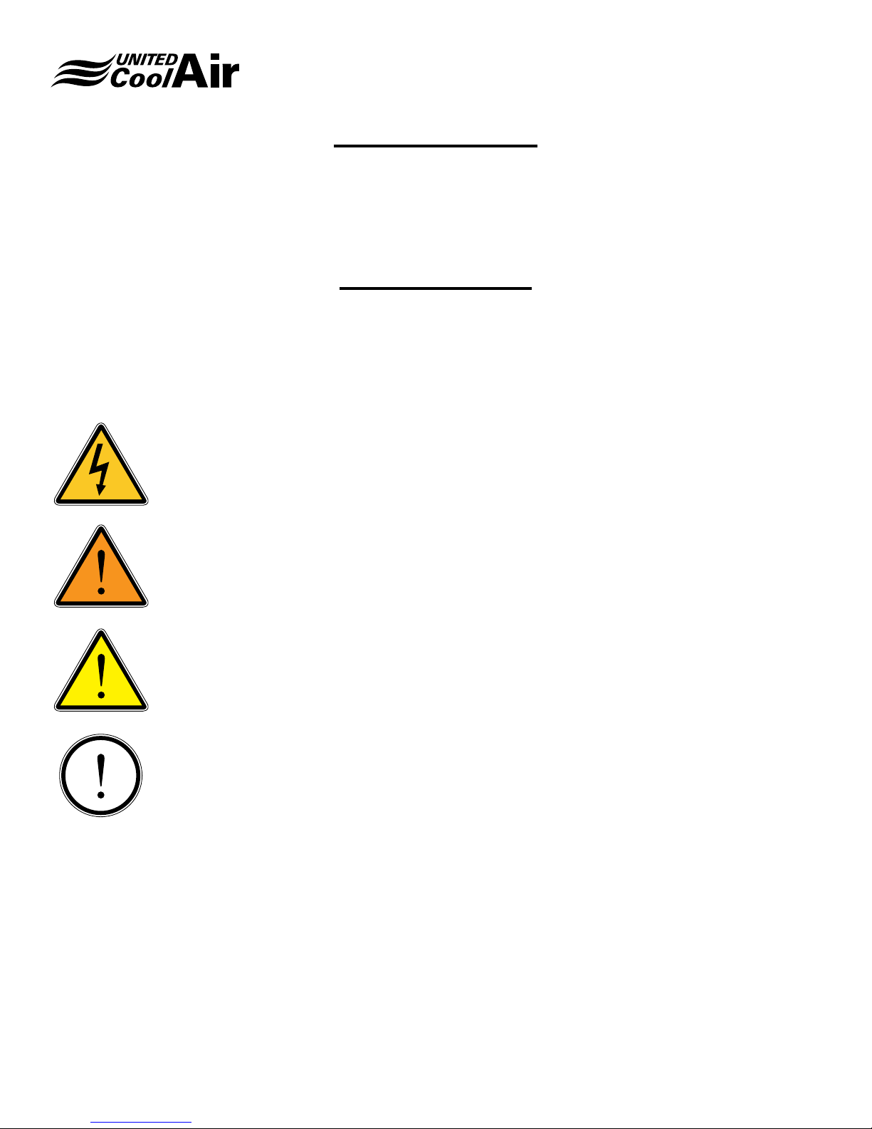
Use of Symbols
This publication includes warnings, cautions and information icons that point out safety related issues or conditions as well
as other pertinent information relative to a safe installation, service or maintenance situation� The following icons should be
interpreted as follows:
ELECTRICAL
HAZARD
WARNING
CAUTION
INFORMATION
The electrical hazard icon indicates the presence of an electrical hazard which
could result in electrical shock or death�
The warning icon indicates a potentially hazardous situation which could result
in death or serious bodily injury if not avoided�
The caution icon indicates a potentially hazardous situation which may result in
minor or moderate injury if not avoided�
The information icon indicates a situation that may result in equipment or
property damage� The information provided alerts the reader to relevant facts
and/or conditions�
Subject to change without notice. 40.20-IM (0118)
4
Installation, Operation and Maintenance Manual
General Information
VariCool EZ-Fit
NOTE: This manual covers the standard unit congurations.
Since many units are built-to-order some of the
information provided may not directly apply to this
specic unit.
Inspection of Equipment
Upon receiving of the unit, carefully inspect all sections for
visible or concealed interior / exterior damage� If damage
occurred during transit, contact the freight carrier immediately
and le a damage claim report.
Inspect the unit data plate to verify the model unit that was
ordered is what has been received�
Some options / accessory items may have been shipped
loose in one or more boxes� These may have been delivered
to another location, or possibly within the unit� If shipped with
the unit there will be a sticker that identies where in the
unit the shipped loose items are located. Conrm that all of
these options / accessory items are also available and that
no damage has occurred�
Handling
To help facilitate handling, most units or modules are set on a
wooden skid� Use caution when moving the unit or modules
so that damage does not occur when moving each piece to
the nal installation location within the structure.
The units or modules can be moved by the use of a crane,
fork lift, pallet jack or roller bars as appropriate� Under no
circumstances should the unit or modules be “walked” on
the corners of the skid or unit�
If a crane, cables or slings are used to move a unit or module,
spreader bars must be used to protect each section’s cabinet
structure�
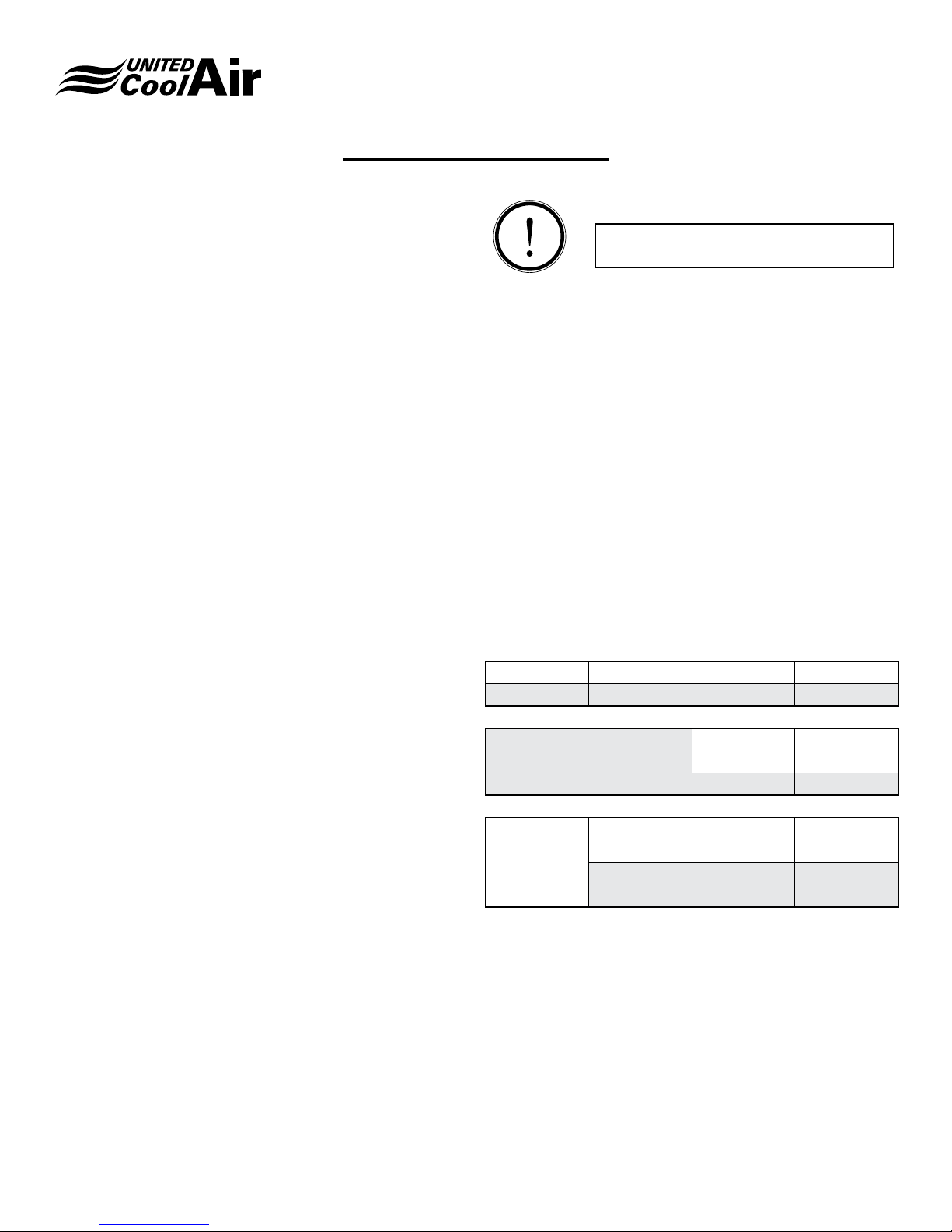
INFORMATION
Unit should NOT be located in space
subject to freezing temperatures�
Location
Before unit can be installed, a thorough study should be
made of the structure� Attention must be given to:
A. Floor, ceiling or wall load limitations as appropriate
B. Required service clearances
C. Condensate removal, trapping and disposal
D. Location of wiring and safety devices
E. Ductwork sizing and connections are per industry
standards
F. Maintenance access
G. Mounting location is level in both horizontal planes
H. If appropriate, water piping location and connection
conguration
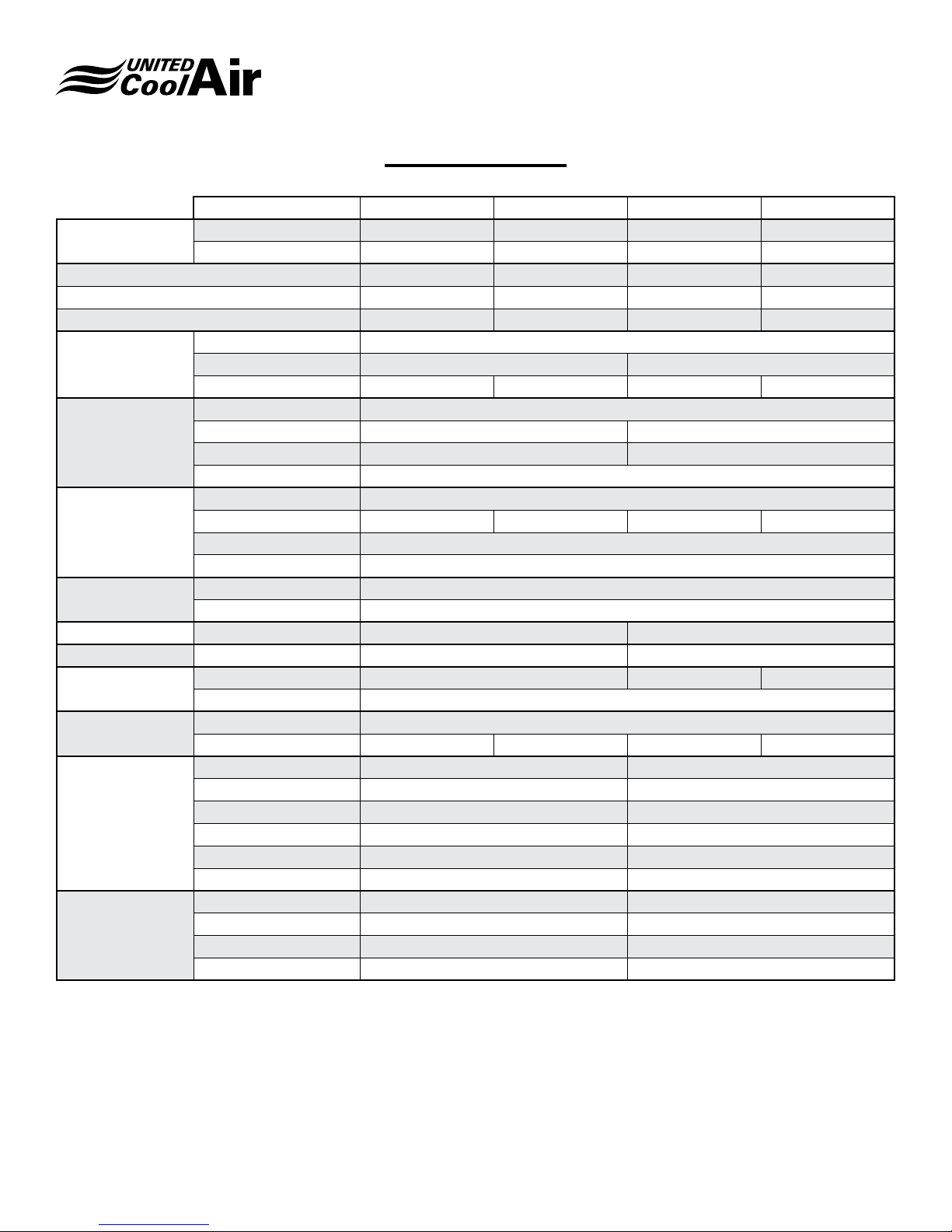
Application Data
Voltage 208 / 230 460 575
Variation 187 / 253 414 / 504 518 / 632
Cooling
(Air Entering Evaporator)
Water-Cooled
DB
(min./max.)
WB 57 / 72
GPM / Ton
(min./max.)
Leaving Water
(min./max.)
65 / 110
2.5 / 3.5
60 / 115
Subject to change without notice. 40.20-IM (0118)
Note: Not all combinations may be valid.
5

Installation, Operation and Maintenance Manual
Service Clearances
VariCool EZ-Fit
36
24
24
TOP
Single DWDI Modules
TOP
36
24
24
24
36
24
TOP TOP
36
24
242424
Dual Modules Single DDP Modules
Notes:
(a) Service clearances apply to all air path congurations.
(b) Service clearances apply to all size units�
(c) Service clearances apply to both DWDI and DDP blower models in dual module conguration.
Subject to change without notice. 40.20-IM (0118)
6

Condensate Drain
Each EZ-Fit evaporator has a condensate drain connection
in the base frame (Ref� Figure 1)� If the application contains
dual modules two (2) drain traps are required�
Traps will need to be connected to the 1-1/4” NPT drain
connection(s) (Ref� Figure 1)�
A condensate drain trap must be eld fabricated and
installed� The purpose of the trap is to neutralize the negative
pressure created within the blower cabinet�
The negative pressure can vary from less than 1” up to 3”
column. The condensate trap must be of sufcient depth
in water column to permit the condensate to ow from the
drain pan. Failure to have a sufcient drain trap will cause
the condensate to overow the drain pan or to cause the unit
to shut down on the drain pan overow safety.
The “A” dimension (Ref� Figure 2) must equal or exceed the
negative static pressure developed by the supply air blower�
The “A” dimension will be unique for each unit application�
The trap must be 2-1/2” deep to maintain a water seal under
all operating conditions, especially during blower start-up�
It is highly recommended that the trap be primed with water
prior to start-up�
Each trap must be piped to a suitable waste drain�
Installation, Operation and Maintenance Manual
VariCool EZ-Fit
1�047
Condensate Drain
1-1/4" NPT
4�276
Figure 1 - Condensate Drain Location
Plugged
Removable
Cleanout
A
2�5
Min
3�5
Figure 2 - Condensate Trap Dimensions
Subject to change without notice. 40.20-IM (0118)
7
Installation, Operation and Maintenance Manual
VariCool EZ-Fit
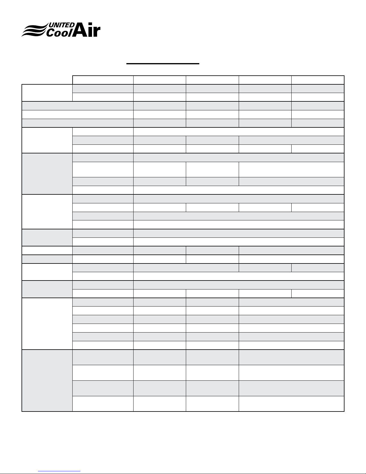
Physical Data
Model 12 15 20 25
Capacity (a) (MBH)
CFM 4800 6000 8000 9000
GPM 36.0 45.0 60.0 72.0
EER 15.1 14.4 14.8 14.1
Blower
Filter
Evaporator
Coil
Condenser
Return Air Duct Size 51-3/8” H x 40” W 55” H x 50-1/2” W
Supply Air Duct Size 16-1/4” H x 18-7/8” W 19” H x 22-3/16” W
Compressor
Refrigerant
Weight (b)
(Net Operating)
Dimensions
(a) Capacity based on 80° F DB / 67° F WB with 85° F EFT
(b) Basic unit only� Options will add weight for general purposes only actual charge may vary due to options and available heat
exchangers as ordered�
Total 165.8 202.0 260.2 300.9
Sensible 117.1 143.5 187.7 213.0
Type (QTY) DWDI
Size (Dia.) 15 - 15 18 - 18
CFM Range 2200-5800 2600-6900 3500-9500 3500-9500
Type Pleated Throwaway
Size (All 2” Thick.) 15 x 20 / 20 x 20 18 x 25
Qty 4 / 2 6
Efciency MERV 8
Type Interlaced
Face Area (Sq. Ft.) 10.6 12.7 17.3 17.3
Rows 4
FPI 12
Type Co-Axial
Working Pressure - Fluid 400 psig
Type Hermetic Scroll
Qty 2
Type R-410a
Lbs-Ozs 10.5 13 15 17
Evaporator 375 525
Condensing 800 1075
Blower (DWDI) 475 575
Blower (DDP) 500 650
Assembly w/ DWDI 1650 2175
Assembly w/ DDP 1675 2250
Evap. & Filter 54” W x 21-1/2” D x 56” H 64” W x 21-1/2” D x 59” H
Comp. & Cond. 54” W x 31-1/2” D x 56” H 64” W x 34” D x 59” H
Blower 54” W x 48” D x 32” H 64” W x 50-1/2” D x 34” H
Assembly 54” W x 53” D x 88” H 64” W x 55-1/2” D x 93” H
Subject to change without notice. 40.20-IM (0118)
8
Installation, Operation and Maintenance Manual
Physical Data continued
Model 30 35 40 45
Capacity (a) (MBH)
CFM 12000 14000
GPM 90.0 105.0
EER 14.0 14.0
Blower
Filter
Evaporator
Coil
Condenser
Return Air Duct Size 69” H x 60” W 69” H x 64” W
Supply Air Duct Size 24-7/8” H x 15-1/2” W 24-7/8” H x 19” W
Compressor
Refrigerant
Weight (b)
(Net Operating)
Total 382.2 451.6
Sensible 283.5 330.7
Type (QTY) DDP (2)
Size (Dia.) 16.5 18.2
CFM Range 4800-13000 5500 - 14900
Type Pleated Throwaway
Size (All 2” Thick.) 24 x 20 / 20 x 20
Qty 6 / 3 2 / 5 / 2
Efciency MERV 8
Type Interlaced
Face Area (Sq. Ft.) 23.9 27.1
Rows 5
FPI 10
Type Co-Axial
Working Pressure - Fluid 400 psig
Type Hermetic Scroll
Qty 2
Type R-410a
Lbs-Ozs 30 40
Evaporator 1000 1170
Condensing 1340 1570
Blower (DWDI) X X
Blower (DDP) 800 (2) 1040 (2)
Assembly w/ DWDI X X
Assembly w/ DDP 3940 4820
Evap. & Filter
69” W x 27-1/2”
D x 71” H
20 x 20 / 20 x 24
/ 24 x 24
76” W x 29-1/2”
D x 71” H
VariCool EZ-Fit
Comp. & Cond. 69” W x 34” D x 71” H 76” W x 34” D x 71” H
Dimensions
Blower
Assembly
(a) Capacity based on 80° F DB / 67° F WB with 85° F EFT
(b) Basic unit only� Options will add weight for general purposes only actual charge may vary due to options and available heat
exchangers as ordered�
Subject to change without notice. 40.20-IM (0118)
34-1/2” W x 56-1/2”
D x 34” H
69” W x 56-1/2”
D x 105” H
38” W x 58-1/2”
D x 34” H
76” W x 58-1/2”
D x 105” H
9

Installation, Operation and Maintenance Manual
Mounting and Placement
VariCool EZ-Fit
Suggested Assembly Sequence
1. Set Evaporator section in place�
2. Set Compressor / Condensing section in place�
a. On Dual Module systems connect the water pipes�
3. Connect resealable refrigerant ttings.
4. Attach tie plates
5. Set Blower section in place�
6. Attach tie plates�
a. On Dual Module systems connect the electrical from
one module to the other�
NOTE: If space is limited in the mechanical room it may
be advantageous to suspend the blower section(s)
temporarily as the initial step.
Each module has three or more sections� If the system is
comprised of dual modules, there will be left hand and right
hand sections�
Each section will be labeled as to which system it is� These
labels are typically something such as AC-1, AC-2 or AHU1, AHU-2, etc� Make sure when mating up the sections that
each section is correctly matched for the appropriate module�
Additionally, when a dual module system is being assembled
there will also be an indication as to which sections are
left hand (LH) or right hand (RH)� Left and Right hand is
determined when viewing the unit from the control box side
(side opposite the lters).
Each section is also alphabetically labeled so that each
section can be mated properly� Set the sections so that point:
A aligns to A
B aligns to B
C aligns to C
etc�
Please ensure that it is recognized that the ezt requires
support on the bottom middle of the unit� This means that
corner loading is insufcient for the task of placing an ez t
unit. The ez-t requires support on the corners, the middle
of each section, and wherever sections come together� This
observation is critically important, if these methods are not
followed refrigeration pipe breakage will occur and UCA will
refuse warranty of any kind of pipe breakage or leaks if an ez
t module is not supported by the means supplied herein this
section. The UCA Recommended way is shown on gure 3B
notice where the middle beam supports the mid-section of
the unit�
Figure 3A -Spring Isolation Base
Mounting Options
When installing any oor mounted unit, it is sometimes
desirable to include some form of vibration isolation� Please
note that the unit frames have not been designed for corner
point only loading with vibration isolation methods�
Vibration isolation can be achieved by use of wafe pads
or spring isolation. These are eld supplied and applied
accessory items� The selected choice of vibration isolation
should be placed as appropriate in the sequence of
placement of the unit sections�
Subject to change without notice. 40.20-IM (0118)
Figure 3B -Unit Positioned On Spring Isolation Base
10
Installation, Operation and Maintenance Manual
VariCool EZ-Fit
Another equally recognized and recommended base support
of the ez t is shown on gure 3C which is channel steel
of an approved gauge to support the weight, simply placed
underneath the unit in 4 locations per module or 7 locations
per dual module pairing. Place wafe pad type furnace pads
underneath the channel iron inside the C facing down for
sound dampening� It is important that the channel does not
touch the ground or sound dampening will not occur� It is
also important that all the channels are level before placing
the unit atop them� Please note the locations of the pads�
If height and other reasons prevent adequate space for
framing wafe pads alone may be used reference gure
3E� It is highly recommended that each pad be of identical
height and that the pads are kept no smaller than 4”x 4”� You
will need at minimum 30 pads to support the ezt properly.
Additional pads; more than the specied count can only help
the units support, the goal is to keep the middle of the unit
from sagging, support under the compressors and water
coils is key�
Figure 3E - Base Option 3 Bottom View
Figure 3C - Base Option 2 Bottom View
Figure 3D - Base Option 2 Unit View
Figure 3F - Base Option 3 Unit View
Subject to change without notice. 40.20-IM (0118)
11
Installation, Operation and Maintenance Manual
VariCool EZ-Fit
Evaporator Section
Start by locating the evaporator section rst. Set each section
as needed, making sure that in dual module applications the
evaporator sections are placed correctly as left hand and
right hand�
Gasket Material
Gasket material has been factory supplied for eld
installation between each unit section� The gasket material
must be installed to minimize air leakage and to help reduce
transmission of noise�
Before applying any gasket material make sure the surface
is clean and dry�
Gasket material, 3” wide, should be applied to those surfaces
identied as “3” in Figure 4 (evaporator and compressor /
condensing section)�
Gasket material, 2” wide, should be applied to those surfaces
identied as “2” in Figure 4 (evaporator and compressor /
condensing section)�
Blower
Section
Compressor / Condenser Section
Next, locate the compressor / condenser section(s)� Again,
make sure the labels align properly for either the single or
dual module applications�
On the refrigerant resealable ttings, apply a few drops of
refrigerant oil to the male coupling halves before starting the
assembly (Ref� to Figure 6)�
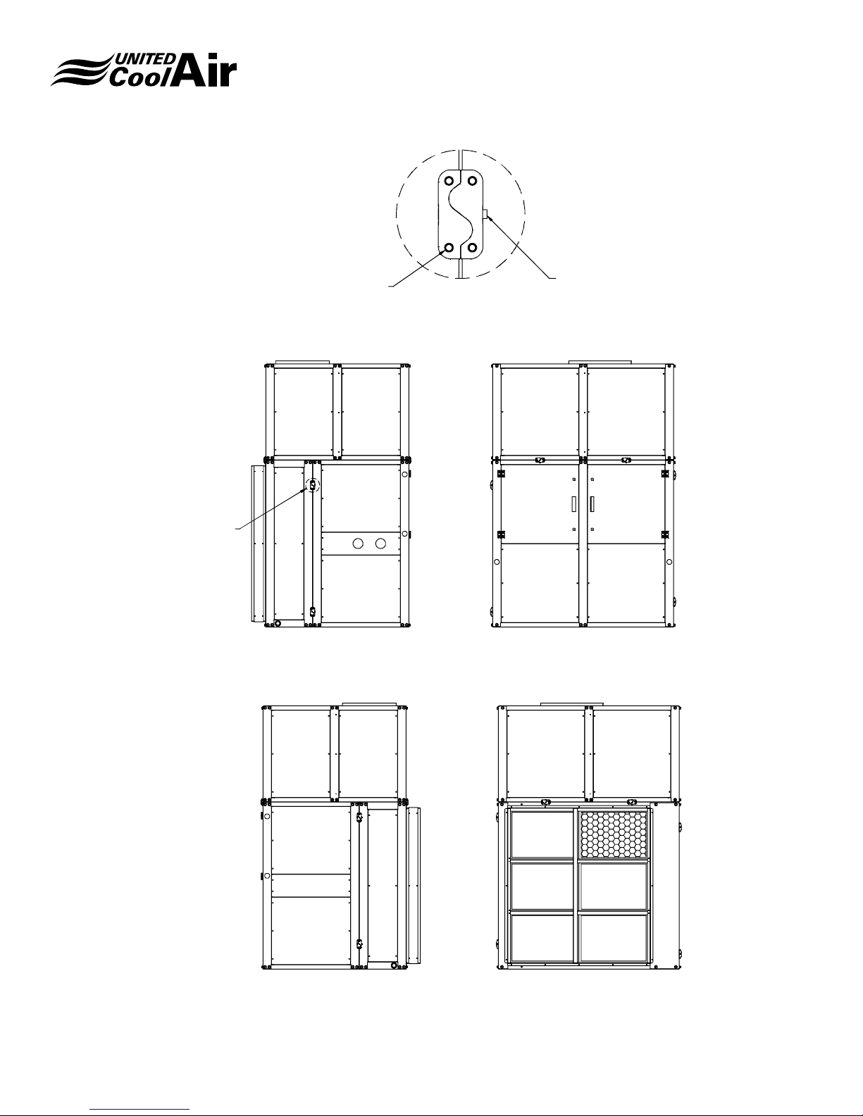
3D-Intelliclamps
Each section of a single module is furnished with
3D-Intelliclamps to facilitate connection to the adjacent
section� These have been installed at the factory during
production and consist of two interlocking halves that mate
and are then bolted together� Once tightened, they ensure
perfect alignment of the mating section surfaces�
Once adjacent sections have been put into place, use the
included hardware to pull sections together until the curved
surfaces of the 3D-Intelliclamps are completely mated�
Evaporator
Section
3
Figure 4 - Gasket Material
Subject to change without notice. 40.20-IM (0118)
2
Condensing
Section
3D-Intelliclamp
12
Installation, Operation and Maintenance Manual
VariCool EZ-Fit
DETAIL "A"
TYP 8 PLCS
MOUNTING SCREWS
MOTOR
IN OUT
LEFT
DETAIL "A"
TIGHTENING SCREW
ELECT
FRONT
VFD
Subject to change without notice. 40.20-IM (0118)
RETURN
AIR
REARRIGHT
Figure 5A 20 - 70 Ton Single
13

Installation, Operation and Maintenance Manual
TY
VariCool EZ-Fit
DETAIL "A"
P 16 PLCS
LEFT
MOUNTING SCREWS
MOTOR
IN OUT
DETAIL "A"
ELECT
TIGHTENING SCRE W
VFD
VFD
FRONT
ELECT
MOTOR
Subject to change without notice. 40.20-IM (0118)
NRUTERNRUTER
RIARIA
RAER THGIR
Figure 5B 20 - 70 Ton Dual
14
 Loading...