

Page 1

Marvel Plus
DISCONTINUED
For Reference Only
MICROPROCESSOR CONTROLLER
Installation, Operation and Maintenance Manual
Effective October 2018
***Interactive PDF***
Page 2
Contents
Installation, Operation and Maintenance Manual
Marvel Plus
Contents ������������������������������������������������������������������������������2
Use of Symbols �������������������������������������������������������������������3
ELECTRICAL HAZARD �������������������������������������������������������3
WARNING ���������������������������������������������������������������������������3
CAUTION ����������������������������������������������������������������������������3
INFORMATION ��������������������������������������������������������������������3
Display Mounting Location ��������������������������������������������4
Connecting Cable ����������������������������������������������������������4
OPERATING THE CONTROLLER ��������������������������������������5
Unoccupied Mode ���������������������������������������������������������6
Unoccupied Override Mode �������������������������������������������6
System Operation ����������������������������������������������������������6
Supply Air Temperature Control ������������������������������������6
Return Air Temperature Control (Option) �����������������������6
Sequence of Operation �������������������������������������������������6
Humidication (Option) ��������������������������������������������������7
Dehumidication (Option) ����������������������������������������������7
Reheat Mode (Option) ���������������������������������������������������7
Air Side Economizer (Option) ����������������������������������������7
Air Side Economizer - Compressor Assist Mode �����������7
Water Side Economizer (Option) �����������������������������������7
Water Side Economizer - Compressor Assist Mode ������7
STATIC PRESSURE TRANSDUCER
(DUCT MOUNT) WITH VAV OPTION ���������������������������������8
MOUNTING �������������������������������������������������������������������8
WIRING �������������������������������������������������������������������������8
Chilled Water Coil (Option) ��������������������������������������������9
Freezestat (Option) �������������������������������������������������������9
Marvel Plus Display Screen Information �����������������������9
System Status ���������������������������������������������������������������9
Blower / Motor Screen ���������������������������������������������������9
Compressor Discharge Pressure Screen ��������������������10
System Status Screen �������������������������������������������������10
Water Status Screen ���������������������������������������������������10
Compressor Status Screen �����������������������������������������10
Compressor Minimum On Status Screen �������������������� 11
Compressor Minimum Off Status Screen ��������������������11
Analog Outputs Status Screen ������������������������������������ 11
Occupied / Unoccupied Override Screen �������������������� 11
Menu and Sub-Menu Areas �����������������������������������������12
Enables �����������������������������������������������������������������������12
System Enables ����������������������������������������������������������12
Constant or Variable Air Flow Enables ������������������������12
Set Points ��������������������������������������������������������������������������12
Set Points (continued) �������������������������������������������������13
Cooling Mode ��������������������������������������������������������������13
Heating Mode ��������������������������������������������������������������13
Set Points (continued) �������������������������������������������������14
Morning Warm-up ��������������������������������������������������������14
Warm-Up Set Points ����������������������������������������������������14
Morning Cool Down �����������������������������������������������������14
Cool Down Set Points �������������������������������������������������14
Set Points (continued) �������������������������������������������������15
Alarm Set Points ����������������������������������������������������������15
Run Hours �������������������������������������������������������������������15
Day Min/Max Screen ���������������������������������������������������16
Alarm History Screen ��������������������������������������������������16
Set Day, Time, Date and Daylight Savings Screen �����16
Schedule ���������������������������������������������������������������������16
Morning Warm-up Time �����������������������������������������������17
Unoccupied Humidity Control Screen �������������������������17
BMS Setup Screen ������������������������������������������������������18
BMS Reset Function Screen ���������������������������������������18
Change Password Screen �������������������������������������������18
Technicians Menu ��������������������������������������������������������18
Temperature Unit Screen ��������������������������������������������18
Manual Analog & Digital Control ����������������������������������19
Sensor Calibration �������������������������������������������������������20
Digital Inputs ����������������������������������������������������������������22
Alarm Logic Manual Reset Screen ������������������������������22
Economizer Setup Screen �������������������������������������������22
BMS Economizer Interface Screen �����������������������������23
Water Flush Mode Screen �������������������������������������������23
Water Valve Position Screen ���������������������������������������23
Duct Static Pressure Screen ���������������������������������������23
High Duct Static Pressure Screen �������������������������������24
Change Passwords Screen �����������������������������������������24
Software Version Screen ���������������������������������������������24
Control Board Screen ��������������������������������������������������24
LIMITED WARRANTY �������������������������������������������������25
FACTORY TESTED ����������������������������������������������������25
Subject to change without notice. 120.5-IM (1018)
2
Page 3
Installation, Operation and Maintenance Manual
Marvel Plus
Use of Symbols
This publication includes warnings, cautions and information icons that point out safety related issues or conditions as well
as other pertinent information relative to a safe installation, service or maintenance situation� The following icons should be
interpreted as follows:
ELECTRICAL HAZARD
WARNING
CAUTION
INFORMATION
The electrical hazard icon indicates the presence of an electrical hazard which
could result in electrical shock or death�
The warning icon indicates a potentially hazardous situation which could result
in death or serious bodily injury if not avoided�
The caution icon indicates a potentially hazardous situation which may result in
minor or moderate injury if not avoided�
The information icon indicates a situation that may result in equipment or
property damage� The information provided alerts the reader to relevant facts
and/or conditions�
Subject to change without notice. 120.5-IM (1018)
3
Page 4
ELECTRICAL HAZARD
Only a qualied licensed electrician or other individual that
is properly trained in handling live electrical components
should perform the wiring installation� Failure to follow all
electrical safety precautions and industry accepted practices
when exposed to live electrical components could result in
death or serious injury�
INFORMATION
All electrical wiring must be in accordance with NEC
(National Electrical Code), NFPA (National Fire Protection
Agency) most current versions as well as any applicable
state or local codes�
INFORMATION
Unit wiring and components have been designed for the
specic unit application and factory assigned controls.
Do not use the unit transformers or alter the unit wiring to
interface any eld supplied accessories or controls.
Installation, Operation and Maintenance Manual
Marvel Plus
ash memory (4 Megabytes). An on-board real time clock
maintains programming during a loss of power� All critical
control points such as system set points, system schedules,
alarm set points, and alarm history are stored in non-volatile
memory� Each Marvel Plus controller has the ability to
record up to 50 alarms/faults under an alarm history page
to allow technicians to scroll through alarm history to view
critical operating data temperatures and optional discharge
refrigerant pressure (units with head pressure control option)
at the time of failure�
The Marvel Plus wall mount terminal is used to interface
with the Marvel Plus Main Board microprocessor through
the on-board display and keypad� The software stored in the
ash memory of the Marvel Plus Main Board microprocessor
was designed with menu/sub-menu driven dis- play screens
allowing customers to easily navigate through the menus
and sub-menus for setup of their systems�
Marvel Plus Main Board microprocessors allow for connection
to some of the more widely used Building Management
Systems without requiring a Gateway to interface� For
optional communications with BACnet™, Modbus, or
Lonworks®, an add-on Serial or IP based communications
card is required�
Display Mounting Location
The wall display does not provide any temperature or
humidity sensing functions� Therefore, the display can be
mounted either in the space being conditioned or in a remote
location�
Connecting Cable
The Marvel Plus is supplied with a factory provided
WARNING
Moving fan drives and high horsepower blowers/motors can
cause injuries� Before applying power to the unit, make sure
all service access panels/doors are closed and fastened/
latched to prevent injuries from the moving drives or from
blowing open� Connect power to the unit at the main power
supply. Next, apply power at the eld in- stalled service
disconnect switch�
The Marvel Plus controller is designed to control United
CoolAir Variable Air Volume congured units. The Marvel
Plus controller package consists of a double microprocessor
design control system made up of a Marvel Plus main control
board and a Marvel Plus wall mount terminal “display and
keypad” (standard conguration).
The Marvel Plus microprocessor main board is a 16 bit
microprocessor programmable controller with on-board
Subject to change without notice. 120.5-IM (1018)
communications cable� A factory supplied cable MUST be
used when connecting the Marvel Plus display to the Marvel
Plus control board�
The standard cable length provided is 100 feet� Any excess
length can be placed where practical� It should be noted
that any excess cable should not be coiled up as this may
generate EMF that could affect the control operation� As
always, care must be taken not to place this control cable in
proximity to any high voltage power wiring�
The maximum length of cable in the standard conguration
will be 500 feet� Beyond 500 feet a different type of cable
and cable gauge must be used�
If a longer length of cable (i�e� more than 100 feet) is required,
please contact a United CoolAir Distributor�
4
Page 5
Installation, Operation and Maintenance Manual
Marvel Plus
Please note that if at the time of installation or start-up it is
found that the 100 feet is not sufcient, the system can still
be started and set up� The required length of cable can then
be ordered as necessary from United CoolAir�
1. The display can be located next to the unit or other
suitable location temporarily�
2. The display is required for monitoring the system or for
making changes to the set points and also to have the
audible alarm function�
OPERATING THE CONTROLLER
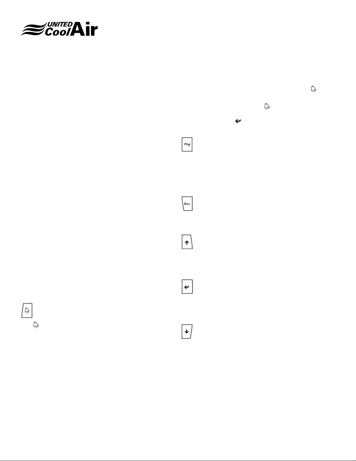
To operate the control system, there are six basic buttons
on the Marvel Plus wall mount terminal which are used to
change settings, time schedules, system setup, and view
alarms critical and non-critical alarms� (Refer to Figure 1)
Some alarms are just simple faults known as indicators
which are not harmful to the operation of the unit but may
require attention in the near future� Pressing the
will reveal what alarm caused the system to shut down�
To reset an alarm, press the
displays “NO MORE ALARMS, Press ENTER to RESET”�
Simply pressing the button will reset the alarm when on
the NO MORE ALARMS screen�
button until the screen
button
PROGRAM BUTTON
The Prg button is used to program the system’s set
points, alarm thresholds, view alarm history, adjust sensor
calibration, enable system operation, view run hours,
set occupied/unoccupied schedules, and much more� A
complete listing is under the section called menus�
ESCAPE BUTTON
The escape button is used to go back to the previous menu
screen�
UP BUTTON
The up button is used to scroll upward through the screens
and menus, increase the value of a setting, or to toggle a
component ON/OFF�
Figure 1 - Wall Display / Keypad
An explanation of each button is as follows:
ALARM BUTTON
The button is used for viewing the present alarms with
the system� There is a built in watch-dog alarm constantly
monitoring for alarm conditions with each of the system
safeties. It will constantly ash on and off to show that the
watch-dog alarm is operating� During an alarm condition, the
button illuminates a continuous Red� Depending on the type
of alarm, the system may shut down or continue to operate�
ENTER BUTTON
The enter button is used to conrm temperature, humidity,
or pressure settings, and conrm selected components. It is
also used to clear alarms once the alarm is viewed�
DOWN BUTTON
The down button is used to scroll downward through the
screens and menus, decrease the value of a setting, or to
toggle a component ON/OFF�
Subject to change without notice. 120.5-IM (1018)
5
Page 6
Installation, Operation and Maintenance Manual
Marvel Plus
Unoccupied Mode
When the unit is in the Unoccupied Mode, the supply air
blower will ramp back to minimum speed and the unit will
maintain the return air temperature between the High and
Low Temperature Night Set Back Temperature Set Points�
Any optional Outdoor Air Dampers and Airside Economizer
Dampers connected to the system are closed� When the unit
is in the Occupied Mode, the system will be fully operational�
Any interlocked fresh outdoor air dampers shall be open and
airside economizer dampers shall be modulated based on
economizer availability status demand�
Unoccupied Override Mode
Unoccupied Override is available to override the Unoccupied
Mode of operation during after hours tenant occupancy�
When activated, the system returns to the Occupied mode
for the specied adjustable (1 hour increments) time period.
System Operation
There are two methods of control depending on the
application, options ordered, and functions of the system�
The two methods of control are Supply Temperature Control
and Return Temperature Control� Please refer to each
specic method of control for details of operation of each
function within the system� The method of control is preset
at United CoolAir specic to customer ordered application.
Supply Air Temperature Control
Supply Temperature Control monitors the supply
temperature to determine if the supply air temperature is
above the supply air temperature set point� If the supply
air temperature is above the supply temperature set point
plus Band set point, mechanical cooling, optional waterside
economizer, or optional airside economizer is sequenced to
maintain the supply air temperature based on a percentage
of cooling demand required� The amount of cooling demand
is determined by how far the supply air temperature is above
the supply air temperature set point�
If the system has the Morning Warm Up Option, morning
Warm Up is sequenced based on return air temperature and
morning Warm Up set points�
If the system has the Morning Cool Down Option, morning
Cool Down is sequenced based on the return air temperature
and morning cool down set points�
sensor is factory provided but must be eld installed. The
return air sensor will be used to determine the mode of
operation Cooling, Heating, Humidication, Dehumidication
and/or Reheat�
Sequence of Operation
After power is applied to the system from the main power
supply, the unit must be started through the Marvel Plus wall
mount terminal� To start the unit, press and hold the ENTER
button for 5 seconds� To stop the unit, press the ENTER
button again and hold for 5 seconds�
Once the system is started through the Marvel Plus Wall
Control, the supply air blower will start after the factory
default 15 second time delay (eld adjustable) times out.
When the unit is in the occupied mode, the supply air
blower will start at the minimum blower speed to supply the
minimum required amount of air ow. Once at the minimum
speed, the controller will verify that the blower is operating by
checking the airow proving switch. The high duct pressure
safety switch is also veried for possible high duct pressure
conditions� If both safety switches are closed, the controller
will ramp the VFD to maintain the supply air blower at the
static pressure set point�
If the pressure in the ducting increases above the high duct
static pressure switch setting, the system will shut down all
modes of operation� The supply air blower will be shut down
and an audible alarm will be generated and displayed in text
on the Marvel Plus wall mount terminal under the
The bottom line of the opening screen for System Status
will also display “Off by High Press AL” before entering the
button�
At any time, if the Marvel Plus controller monitors that there
is a loss of air ow, the controller will shut down all modes
of operation to protect the system� The supply air blower will
shut down and an audible alarm is generated and displayed
in text on the Marvel Plus wall mount terminal under the
button� The bottom line of the opening screen for System
Status will also display “Off by Airow Alarm” before entering
the button�
If both switches are veried and no alarms exist, the controller
will continue with the cooling or optional modes of operation
heating, humidication, dehumidication, morning warm up
or morning cool down�
button�
Return Air Temperature Control (Option)
If the application requires both cooling and heating or
requires humidication or dehumidication, a return air
Subject to change without notice. 120.5-IM (1018)
6
Page 7
Installation, Operation and Maintenance Manual
Marvel Plus
Humidication (Option)
If the system has the Humidication Option, humidication
will operate based on return air humidity� When the return air
humidity is less then the return air humidity set point minus
the Band set point, humidication is enabled. Humidication
is then sequenced ON and OFF based on the return
air humidity requirement or humidication demand. The
percentage of humidication demand is determined by how
far the return air humidity is below the return air humidity set
point�
Dehumidication (Option)
If the system has the Dehumidication Option,
dehumidication is sequenced based on return air humidity.
When the return air humidity is greater than the return air
humidity set point plus the Band set point, dehumidication
mode is enabled. Dehumidication is then sequenced /
staged ON and OFF by cycling compressors based on the
dehumidication requirement or dehumidication demand.
The percentage of dehumidication demand is determined
by how far the return air humidity is above the return air
humidity set point�
Reheat Mode (Option)
If the system has the Dehumidication Option and the
optional factory provided heaters or hot gas reheat coil and
valve, the heaters/hot gas reheat coils are available for the
Reheat Mode Option� The heater(s) will be activated for the
Reheat Function during the Dehumidication Mode. Reheat
function is based on both Return Air Temperature and
Supply Air Temperature and their respective set point� If the
return air temperature falls below the return air temperature
set point or the supply air temperature falls below the supply
air temperature set point, the reheat is brought on and
applied based on whichever demand for heating is greater�
The reheat demand is based on how far the temperature is
from the set point and whichever demand is greater (reheat
demand based on supply air temperature or reheat demand
based on return air temperature)� For systems with multiple
stages of heater, the quantity of heaters for Reheat Mode
is determined by the heating demand based on return air
temperature�
Air Side Economizer (Option)
If the system has the Airside Economizer Option, the system
will utilize the airside economizer when the outdoor air
enthalpy is less than return air enthalpy and the outdoor
air temperature is less than the outdoor air temperature set
point minus the Band set point� Once the outdoor air enthalpy
is veried, the Marvel Plus controller sends a modulating
signal (0-10vdc) to the eld interlock terminal strip as shown
on the electrical diagram provided with the unit� The signal
provided will maintain the supply air temperature as close
to the supply air temperature set point as possible until the
return air temperature (cooling requirement) is satised.
INFORMATION
The minimum position damper setting may in some
instances affect system operation if too much outdoor air is
continuously introduced to the space being controlled�
Air Side Economizer - Compressor Assist Mode
Mechanical Cooling Assist is a function available for
applications where the outdoor air temperature cannot meet
the cooling demand requirements� The Mechanical Cooling
Assist function has an adjustable time delay (minutes) before
mechanical cooling compressor stages are energized to
assist with the Airside Economizer option�
Water Side Economizer (Option)
The Water Side Economizer Option provides an economical
method of cooling when a free-cool coil can be utilized� If the
system has a free-cool coil and a cooling tower available,
the system will use free cooling when the water temperature
is below the free-cool temperature setting� If the water
temperature is above the free-cool setting, the system will
use mechanical cooling� If the water temperature is below
the free-cool setting, the water valve for free-cool mode will
modulate open to satisfy the cooling requirement�
Water Side Economizer - Compressor Assist Mode
Mechanical Cooling Assist is a function available for
applications where the waterside economizer function cannot
meet the cooling demand requirements� The Mechanical
Cooling Assist function has an adjustable time delay
(minutes) before mechanical cooling compressor stages are
energized to assist with the Water Side Economizer option�
Subject to change without notice. 120.5-IM (1018)
7
Page 8

Installation, Operation and Maintenance Manual
Marvel Plus
STATIC PRESSURE TRANSDUCER (DUCT MOUNT) WITH VAV OPTION
MOUNTING
The static pressure transducer shown in Figure 3 – Pressure
Transducer must be installed in the main supply air ducting
at a location approximately two-thirds of the distance down
the straightest duct run from the supply air outlet of the unit�
The location must be a non-turbulent area of supply air ow.
Mount the pressure transducer as follows:
1. Remove the pressure transducer’s cover plate screws
using a Phillips head screw driver�
2. Select the mounting location� Install the sensor at the
approximate mid-point/center of the vertical plane of
the ducting�
3. The sensor must be mounted vertically with the
electrical entrance/strain relief facing downward�
4. Drill a 1/2” hole through the face of the duct�
5. Before installing the duct pressure transducer, make
sure the gasket at the base where the duct probe
meets the transducer housing is intact and sealed to
the sensor (so that it will seal the perimeter of the hole
drilled)�
6. Insert the probe into the duct and mount the pressure
transducer using two (2) eld provided #8 sheet metal
screws�
WIRING
Using a minimum 18-20 AWG 300 volt rated two conductor
shielded cable with drain wire make the following electrical
connections�
IMPORTANT: Please observe polarity of this sensor� The “+”
is +24 vdc and the “–“ is the output (4-20 mA) to the Analog
Input of the controller�
7. Connect from the positive terminal “+” inside the
pressure transducer to the unit’s electrical terminal
block TB-DMPT +�
8. Connect from the negative terminal “–” inside the
pressure transducer to the unit’s electrical terminal
block TB-DMPT –�
9. Connect the drain wire to ground at the unit end only�
FIGURE 1 – PRESSURE TRANSDUCER
Subject to change without notice. 120.5-IM (1018)
8
Page 9
Installation, Operation and Maintenance Manual
Marvel Plus
Chilled Water Coil (Option)
If the system has the Chilled Water Coil Option, the chilled
water valve (optional) will be controlled (cycled On / Off
or Modulated) to maintain the supply air temperature set
point based on the cooling demand� The entering water
temperature must be below the chilled water temperature
set point� Cooling Demand is determined by how far the
supply air temperature is above the supply air temperature
set point� The chilled water valve is opened or modulated to
maintain the supply air temperature as close to the supply
air temperature set point as possible�
Freezestat (Option)
Units equipped with the Freezestat option have a freezestat
connected to the refrigerant suction line to monitor outlet
suction temperature from the evaporator coils� If the
temperature falls below the Freezestat xed set point, a
Freezestat Alarm will be present on the Marvel Plus controller�
This is an auto reset type alarm and will continue to reset
to provide cooling� The alarm on the controller is used to
notify the customer of the evaporator coil frosting/freezing
condition and that technical service/ system maintenance is
required�
Marvel Plus Display Screen Information
Each screen listed below has been described for function
within the system� The screens are only representative
of the possible combinations of functions and will change
depending on whether the various options are enabled�
System Status
Home Screen
This screen shows the time and date, return air humidity
option, return air temperature, supply air temperature, and
the status of the system (Occupied/Unoccupied, System ON
or OFF, HEAT, COOL, HUMIDIFY, DEHUM, etc�)�
Press the or buttons to allow navigation through the
main status display screens�
Blower / Motor Screen
U01
Blower VFD
Pressure > 0.12iwc
Frequency > 47.2Hz
This screen shows the readings for blower and motor
conditions� The pressure reading is the static pressure
reading within the duct system� The Frequency reading is
the position or operating point of the supply air blower motor�
The frequency is the VFD output frequency to the motor
based on the static pressure reading and static pressure
set point� As the static pressure decreases, the VFD will be
modulated by the Marvel Plus Main Board microprocessor
to increase the frequency to the motor which will increase
the air volume bringing it closer to the air pressure set point�
Outdoor Sensor Screen
U01
Outdoor Sensors
U01 13:48 05/01/13
Temperature > 061.5°F
Return Hum > 050.0%
Return Temp > 068.1°F
Humidity > 042.2%
Air Economizer > 100%
Supply Temp > 048.2°F
This screen shows the outdoor air conditions� It shows
Occupied
System ON HEAT
Subject to change without notice. 120.5-IM (1018)
the outdoor air temperature and outdoor air humidity� The
Outdoor Sensors information screen will appear only with
the Air Side Economizer option
9
Page 10
Installation, Operation and Maintenance Manual
Marvel Plus
Compressor Discharge Pressure Screen
U01 Refrigerant
Pressure Control
Control Press > 351psi
Compressor 1 > 351psi
Compressor 2 > 307psi
Compressor 3 > 251psi
Compressor 4 > 180psi
This screen is used with the electronic discharge pressure
control option� It shows the refrigerant liquid pressure
readings of all compressors and adjusts the pressure based
on the highest operating pressure of all compressors� The
Control Pressure is determined by the compressor with the
highest operating pressure� The pressure is then adjusted
by modulating the discharge pressure control water valve to
maintain the refrigerant pressure set point�
Water Status Screen
U01 Water
Water Pump ON
Temperature > 40.8°F
Water Econ Dem > 000%
This screen shows the status of the water pump option and
the reading for entering water temperature and percentage
of demand for water economizer mode of operation� This
screen only appears with the water side economizer option�
Compressor Status Screen
U01 Compressor Status
System Status Screen
U01 System Status
Cooling Off
Heating Off
Reheat 100%
Humidify 000%
Dehumidify 100%
This screen shows the amount of demand for cooling,
heating, humidication, dehumidication, and reheat. The
status of cooling, heating, humidication, dehumidication,
and reheat shown on the screen is the amount of cooling/
heating required to meet the set point required�
Compressor 1 > ON
Compressor 2 > ON
Compressor 3 > OFF
Compressor 4 > OFF
This screen monitors the status of the systems compressors�
When the on-board or wall control displays ON, the particular
compressor that has the ON listed next to it should be
operating� The amount of compressors displayed is based
on the number of compressors the unit has available� For a
two compressor system, only compressor 1 and Compressor
2 enable points will appear�
Subject to change without notice. 120.5-IM (1018)
10
Page 11
Installation, Operation and Maintenance Manual
Marvel Plus
Compressor Minimum On Status Screen
U01
Compressor Status
Minimum ON:
Compressor 1 > 000s
Compressor 2 > 000s
Compressor 3 > 000s
Compressor 4 > 000s
There are minimum operating times for the compressors�
The compressors must operate for the minimum time period
before turning off unless there is a critical alarm such as
high or low pressure or condensate overow, etc. that would
require an immediate shut down of the compressor�
Compressor Minimum Off Status Screen
U01
Compressor Status
Minimum OFF:
Compressor 1 > 000s
Compressor 2 > 000s
Compressor 3 > 000s
Compressor 4 > 000s
This screen shows the output status of the VFD/Blower,
the DPC (Discharge Pressure Control) valve, Modulated
Heaters, and the WSE (waterside economizer) valve�
Occupied / Unoccupied Override Screen
U01
Thursday 08:34
May 02, 2013
OVERRIDE MODE
Mode THU OCCUPIED
Override Status OFF
Override Time 2hrs
This screen shows the status of the system’s Occupied/
Unoccupied and Override states� Mode indicates the present
day of the week and occupancy status for that particular day�
Override Status allows the customer to change the occupancy
status during the unoccupied state to the Occupied state�
Override Time is the length of time the system will remain in
the occupied state during Override Mode�
To change the occupancy status to be in occupied override,
press the button� Next, press the or button one
time then press the button again to store the change as
overriding the unoccupied mode� Then press the or
button to set the length of time for the system to remain in
occupied override mode� Press the button one nal time.
There are minimum off times for the compressors� The
compressors must remain off for minimum time period so
that the compressor does not immediately re-energize
based on rapidly rising duct temperature�
Analog Outputs Status Screen
U01 Analog Outputs
VFD/Blower 07.6vdc
DPC Valve 03.5vdc
Heating 00.0vdc
WSE Valve 06.5vdc
Subject to change without notice. 120.5-IM (1018)
11
Page 12
Installation, Operation and Maintenance Manual
Marvel Plus
Menu and Sub-Menu Areas
To enter the menu area, press the Prg button one time� The
active menu ready for selection will be the one with all capital
letters� Each menu item may or may not have submenus�
The “SYSTEM STATUS” menu is the rst menu displayed
when pressing the Prg button� To go into the System
Enables screen, press the
Enables screen appears in capital letters, “SYSTEM
ENABLES”, press the button to enter the system enables
submenu, or to go into another menu, press the or
button until the preferred menu is selected (appears
in capital letters) and press the
menus for each main menu will appear once entered�
button and once the System
button� All additional sub
Enables
U01 System Enables
System ON/OFF ON
Compressor 1 > ON
Constant or Variable Air Flow Enables
U01 System Enables
Enable > VAV
Control by > Supply
This screen allows the user to enable either CAV (Constant
Air Volume) or VAV (Variable Air Volume) control based
on the type of unit and to enable either Supply or Return
Temperature control modes�
Set Points
Return Air
Temperature
Compressor 2 > ON
This screen is the main screen to turn the unit on or off and
enable or disable the compressors� To turn the unit on or
off, or to enable or disable a component on these screens,
press the button to relocate the cursor to the component
to enable or disable� Next, press the or button one
time to toggle the setting on or off; then press the button
again to initiate the change�
System Enables
U01 System Enables
Dehumidification > OFF
Humidification > OFF
Heater 1 > ON
Heater 2 > ON
Heater 3 > ON
Setpoint > 075.0°F
Band > 02.0°F
The Set Points menu is used to adjust the settings for
the specic modes of operation to maintain Return Air
Temperature, Supply Air Temperature, Duct Static Pressure,
etc�
This screen is used to turn dehumidication, humidication
and heater stages on and off�
Subject to change without notice. 120.5-IM (1018)
12
Page 13
Installation, Operation and Maintenance Manual
Marvel Plus
Set Points (continued)
These are the set points for changeover between Cooling
and Heating Modes (when unit is used for heating in
applications without perimeter heat)�
Setpoint is the setting the return air control will maintain�
Band is the setting used to adjust the on/off points�
In applications without perimeter heating/VAV terminal box
heaters, the Return Air Temperature Set Point and Band are
used for changeover between Cooling and Heating modes
of operation�
Cooling Mode
The Return Air Temperature must be above the Return Air
Temperature Set Point plus the Band Set Point for Cooling
Mode to become active� Cooling Mode shall then remain
active until the Return Air Temperature falls below the
Re-turn Air Temperature Set Point� Compressors and/or
Economizer shall then be controlled by the cooling demand
which is determined by the Supply Temperature Cooling
Mode Set Points� The amount of compressors on or off is
determined by the cooling demand�
Heating Mode
Likewise, when the Return Air Temperature falls below the
Return Air Temperature Set Point minus the Band Set Point,
Heating Mode will become active� Once Heating Mode is
activated, heating mode shall remain active until the Return
Air Temperature rises above the Return Air Temperature Set
Point� The amount of heating stages or modulated heating
is then determined by the heating demand� Heating demand
is determined by the Supply Temperature Heating Mode Set
Point and Band�
Return Air
Humidity
Setpoint > 050.0°F
Band > 05.0°F
Return Air Humidity is used to set the control points for
optional dehumidication and humidication functions.
Setpoint is the setting for the humidity control to try to
maintain�
Band is the setting used to adjust the on/off points of the
dehumidication mode or humidication mode.
If the system has humidication, the humidier is energized
when the Return Air Humidity falls below the Return Air
Humidity Set Point minus ½ the band set point�
If the system has dehumidication, the compressors are
energized when the Return Air Humidity rises above the
Return Air Humidity Set Point plus ½ the band set point�
Supply Temperature
Cooling Mode
Setpoint > 055.0°F
Band > 40.0°F
Heating Mode
Setpoint > 090.0°F
Band > 20.0°F
If the system is being used as a cooling/heating unit
(applications with perimeter/VAV box heaters), the Supply
Temperature screen is used to select the Supply Air
Temperature set points for both Cooling and Heating Modes
of operation� The Cooling Mode set point and Band are used
to determine the cooling demand� Cooling Demand will be
100% when the supply sir temperature equals the Cooling
Mode set point plus ½ of the Band setting� Example: Cooling
Mode set point is 55�0° F and the Band is 40�0° F� When the
Supply Air Temperature is equal to or greater than 75�0° F,
the Cooling Demand is 100%�
The Heating Mode set point and Band are used to determine
the Heating Demand� Heating Demand will be 100% when
the supply air temperature equals the Heating Mode Set
Point minus ½ of the Band setting�
Example: Heating Mode Set Point is 90.0° F and the Band
is 20.0° F. When the supply air temperature is equal to or
less than 80.0° F, the Heating Demand is 100%.
Subject to change without notice. 120.5-IM (1018)
13
Page 14
Installation, Operation and Maintenance Manual
Marvel Plus
Set Points (continued)
U01
Static Pressure
Set Point > 1.00iwc
Dead Band > 0.10iwc
Band > 0.15iwc
Reset to > 1.00iwc
This set point is used to adjust static pressure within the
ducting�
Set Point for static pressure is the setting that the VFD will
change the speed for the motor/blower to try to maintain�
Dead Band is the point where no adjustments are made to
the VFD�
Band is the activation point plus or minus ½ of the band
setting before adjustments are made to adjust the static
pressure in the ducting�
Reset is the actual static pressure control set point based
on the amount of static pressure reset applied� The amount
of static pressure reset applied is determined by either the
BMS Static pressure reset or by system static pressure reset
when these features are enabled�
point� Air side economizer will be available as long as the
out- door air enthalpy is less than the return air enthalpy and
the outdoor air temperature is less than the OA set point
plus the OA Band set point� If the outdoor temperature
continues to rise above the OA set point plus the OA Band,
the controller will lock out the air side economizer and revert
to mechanical cooling�
Morning Warm-up
Warm-Up Setpt
Warmup Setpt > 60.0°F
Warmup Band > 04.0°F
Warm-Up Set Points
On Set Point: If the Return Air Temperature falls below the
Warm-up Setpt minus the band when morning warm-up
mode is enabled, the warm-up heaters are energized�
Off Set Point: As the Return Air Temperature rises above the
warm-up Setpt plus the band when morning warm-up mode
is active, the warm-up heaters are de-energized�
Morning Cool Down
U01
Economizer Setpt
OA SetPoint > 55.0°F
OA Band > 05.0°F
This is the Air Side Economizer set point� If the Outdoor Air
Enthalpy is less than the Return Air Enthalpy, the system will
utilize air side economizer as long as the outdoor temperature
is below the economizer set point minus the band set point�
If the outdoor air temperature falls below the OA set point
minus the OA band, the outside air dampers are modulated
open to maintain the cooling demand� If the outdoor air
temperature rises above the outdoor air temperature
set point plus O/A Band, the outside air dampers are
modulated closed or to the minimum damper position set
Subject to change without notice. 120.5-IM (1018)
14
U01
Cool Down Mode
SetPoint > 070.0°F
Band > 04.0°F
Cool Down Set Points
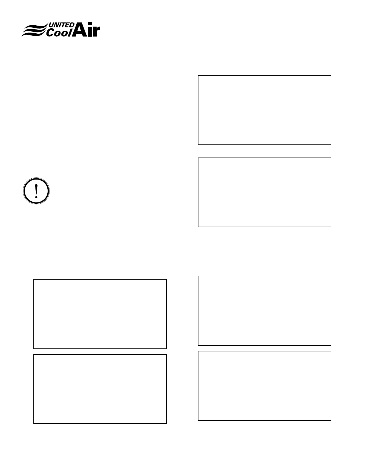
On Set Point: If the Return Air Temperature rises above
the Cool Down Setpt plus the band when morning cool
down mode is enabled, the cool down cycle is energized�
Compressors are brought on to bring the Return Air
Temperature below the cool down set point�
Page 15
Set Points (continued)
Off Set Point: As the Return Air Temperature falls below the
cool down Setpt minus the band when morning cool down
mode is enabled, the cool down mode compressors are
deenergized�
Installation, Operation and Maintenance Manual
Marvel Plus
U01
Supply Temp
High Alarm > 150.0°F
Alarm Set Points
The following alarm set point screens are used to monitor
fault points� The high and low settings are used to monitor
and generate a fault when the temperature or pressure rises
above the high or falls below the low settings� During
the fault, the system will continue to operate�
INFORMATION
Please note that the refrigerant pressure transducer is only
used to monitor head pressure� Each refrigerant circuit has
its own high pressure switch that will lock out its particular
compressor if the discharge pressure rises above the
discharge pressure switches xed trip point.
Alarm delay is the time delay allowed before the system will
show up as a fault� This is used as a means of allowing the
system to recover before a fault is initiated�
U01
Return Temperature
Low Alarm > 038.0°F
Alarm Delay > 030sec
U01
Refrigerant Press
High Alarm > 600psi
Low Alarm > 08psi
Alarm Delay > 005sec
Run Hours
The following screens show the actual run hours of each
component as tracked by the controller� If any of the screens
listed here do not appear, the system does not have that
particular option�
U01
Run Hours (hrs)
High Alarm > 090.0°F
Low Alarm > 090.0°F
Alarm Delay > 120sec
U01
Static Pressure
High Alarm > 3.20iwc
Low Alarm > 0.00iwc
Alarm Delay > 060sec
Subject to change without notice. 120.5-IM (1018)
15
Blower > 01045
Compr 1 > 00121
Compr 2 > 00096
U01
Run Hours (hrs)
Heater 1 > 00247
Heater 2 > 00247
Heater 3 > 00247
Page 16
Installation, Operation and Maintenance Manual
Marvel Plus
Day Min/Max Screen
U01
Current 24/HR
Period
Low High
Temp: 047°F 077°F
Hum: 040% 067°F
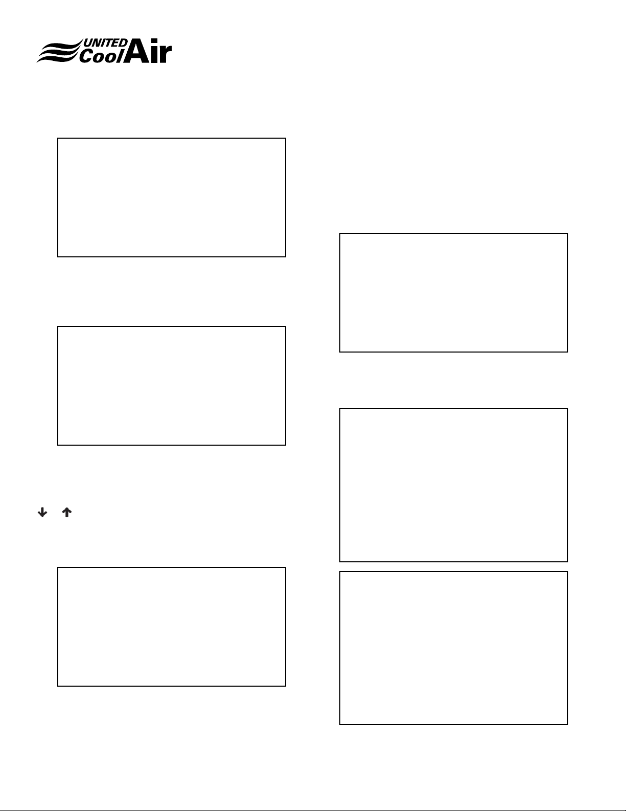
The day min/max screen shows the high and low return air
temperature and humidity for the current 24 hour period�
Alarm History Screen
Alarm History
D: 05/10/13 T: 12:07
HIGH SUPPLY TEMP
Supply Temp: 150
Return Temp: 77
Schedule
For the system to follow an occupancy schedule, a Start
and End period must be set for each day of the week� If
the control schedule is set to 00:00 for both start and end
schedules, the system will remain constantly occupied�
Up to 20 Holiday occupancy schedules may be programmed
into the system� For the holiday schedule, a start date is
programmed and end date is programmed�
Occupied Control
Enable Schedule > Yes
This screen is used to enable or disable the occupancy
schedule�
U01 OCCUPIED
Monday > 07:00
The alarm history screens document the alarms that
occurred, supply and return air temperatures at the time the
alarm occurred and the time and date of alarm� Up to 50
alarms may be stored in the alarm history pages� Use the
or buttons to page through the alarm history pages�
Set Day, Time, Date and Daylight Savings Screen
U01 Real Time Clock
Day: Saturday
Time: 12:16
Date: 05/10/2013
Daylight Savings: Yes
Sets the appropriate day of the week, time, date and daylight savings time� Set up of the real time clock is important
to be able to record alarm history or for following scheduled
occupied and unoccupied times�
Tuesday > 07:00
Wednesday > 07:00
Thursday > 07:00
Friday > 07:00
Saturday > 00:00
Sunday > 00:00
U01 UNOCCUPIED
Monday > 17:00
Tuesday > 17:00
Wednesday > 17:00
Thursday > 17:00
Friday > 17:00
Saturday > 00:00
Sunday > 00:00
Subject to change without notice. 120.5-IM (1018)
16
Page 17
Installation, Operation and Maintenance Manual
Marvel Plus
U01 Holidays 01–07
01 > 00-00 to 00-00
02 > 00-00 to 00-00
03 > 00-00 to 00-00
04 > 00-00 to 00-00
05 > 00-00 to 00-00
06 > 00-00 to 00-00
07 > 00-00 to 00-00
U01 Holidays 15–20
15 > 00-00 to 00-00
16 > 00-00 to 00-00
17 > 00-00 to 00-00
18 > 00-00 to 00-00
19 > 00-00 to 00-00
20 > 00-00 to 00-00
MORNING WARMUP OFF
Monday > 06:30
Tuesday > 06:30
Wednesday > 06:30
Thursday > 06:30
Friday > 06:30
Saturday > 00:00
Sunday > 00:00
Unoccupied Temperature Control Screen
U01
Unoccupied Control
Temp Control > ON
High Temp > 079.0°F
Low Temp > 062.0°F
U01 Holidays 15–20
15 > 00-00 to 00-00
16 > 00-00 to 00-00
17 > 00-00 to 00-00
18 > 00-00 to 00-00
19 > 00-00 to 00-00
20 > 00-00 to 00-00
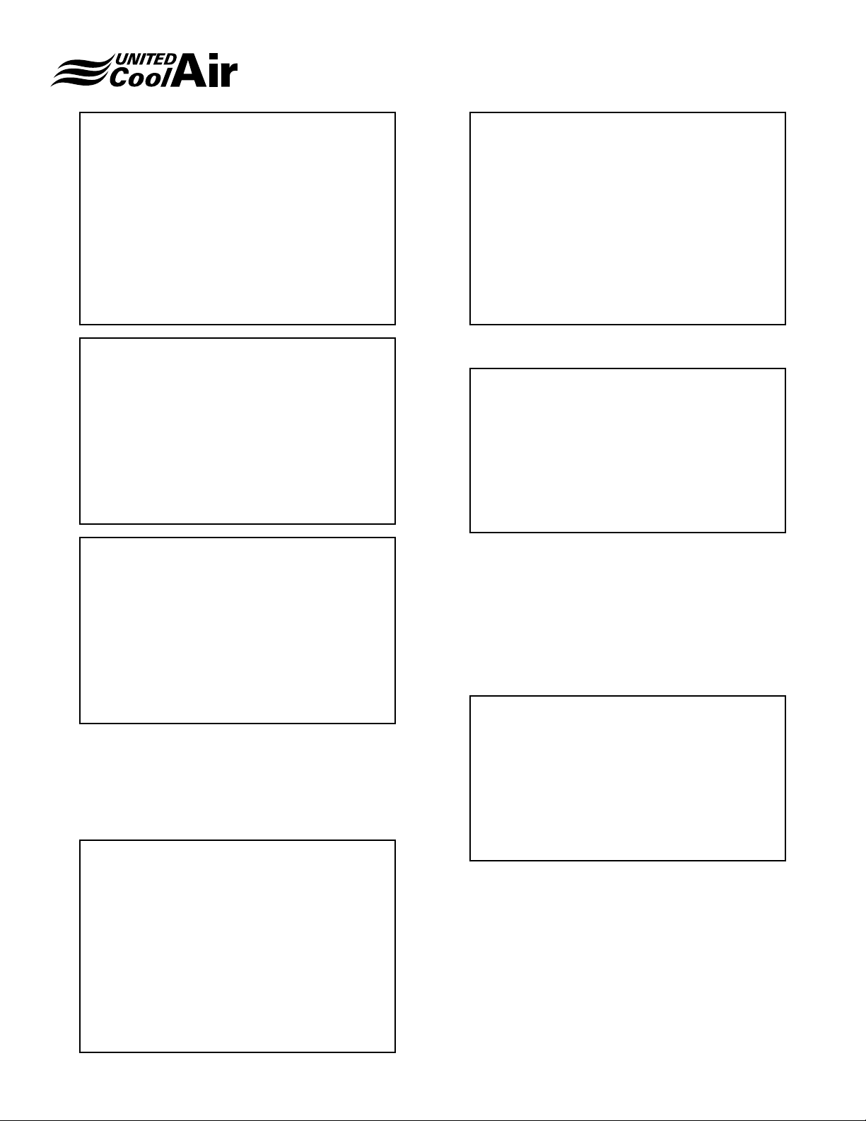
Morning Warm-up Time
Morning warm-up is activated at the times in the ON schedule
screen� Warm-up is deactivated at the times in the OFF
schedule screen�
MORNING WARMUP ON
Monday > 06:00
Tuesday > 06:00
Wednesday > 06:00
The unoccupied control screen sets the temperature swing
that is allowed during the unoccupied time� A temperature
high and a temperature low must be set and Temp control
must be set to ON in order for Unoccupied Control to operate
during unoccupied hours programmed in the previous
section�
Unoccupied Humidity Control Screen
U01
Unoccupied Control
Humidity > ON
High Humidity > 070.0°F
Low Humidity > 035.0°F
High Humidity and Low Humidity set points must be set and
Humidity control must be set to ON in order for Unoccupied
Control to operate during unoccupied hours programmed in
the previous section�
Thursday > 06:00
Friday > 06:00
Saturday > 00:00
Sunday > 00:00
Subject to change without notice. 120.5-IM (1018)
17
Page 18
Installation, Operation and Maintenance Manual
Marvel Plus
BMS Setup Screen
U01
Communications
Protocol : BACnet
Unit Ident : 001
Baud Rate : 19200
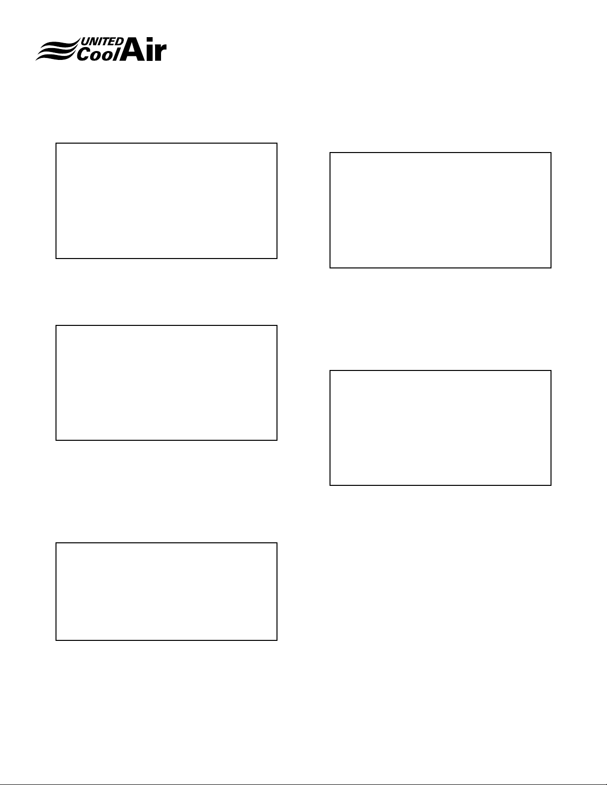
The Communications screen is used to set the type of
communications protocol to be used�
BMS Reset Function Screen
U01
BMS Reset
Function Enable
Supply Temp Setpt > NO
Duct Press Setpt > NO
Technicians Menu
Fan Delays Screen
U01
Fan Delays
Startup > 005s
Airflow Proof > 030s
Unit OFF Delay > 10s
The Fan Delays screen allows customer to set the amount of
delay in seconds for system startup, proof of air ow based
on the amount of time it takes the VFD to ramp up, and the
amount of time in seconds for the unit to turn off (allows for
dissipation of heat energy before shut down)�
Temperature Unit Screen
U01
Temperature Units
If either function on the BMS Reset Function Enable screen
is set to yes, it will allow BMS communications to perform
that function� The Reset would then be performed based on
the reset communications points in the communication point
list�
Change Password Screen
U01
Change Passwords
Level 1 > 0000
Mode > FAHRENHEIT
The Temperature Units screen allows customers to select
the temperature unit to be either Fahrenheit or Centigrade�
Subject to change without notice. 120.5-IM (1018)
18
Page 19
Installation, Operation and Maintenance Manual
Marvel Plus
Manual Analog & Digital Control
Manual control is used to manually operate the digital and
analog inputs and outputs of the system� Selecting ON will
force the input or output to operate� Selecting OFF will force
the input or output to the OFF position� Selecting AUTO will
force the component to operate only with the sequence of
operation�
U01 Manual Dig-In
C1 High Press > Auto
C1 Low Press > Auto
C2 High Press > Auto
C2 Low Press > Auto
Morning Warmup > Auto
Airflow > Auto
U01 Manual Dig-In
WFDP > AUTO
C3 High Press > Auto
C3 Low Press > Auto
C4 High Press > Auto
C4 Low Press > Auto
U01 Manual Analog-In
Water T > OFF 000.0°
O/A Hum > OFF 000.0
O/A Temp > OFF
Return Hum > OFF 000.0%
Return Temp > OFF 000.0°
U01 Manual Dig-Out
Blower > Auto
Water Pump > Auto
Compr 1 > Auto
Compr 2 > Auto
U01 Manual Dig-Out
Heater 1 > Auto
Heater 2 > Auto
Heater 3 > Auto
Manual Dig-In
Filter > AUTO
Hi-Heat > Auto
U01 Manual Dig-Out
Freezestat > Auto
Fan Ovld 2 > Auto
Warm Up > Auto
U01 Manual Analog-In
VFD Input > OFF 00.0Hz
Static Pr > OFF 0.0iwc
Supply T > OFF 000.0°F
Subject to change without notice. 120.5-IM (1018)
19
Page 20
U01 Manual Analog-Out
VFD Input Auto 00.0vdc
Dig Cmpr1 Auto 0.0vdc
Installation, Operation and Maintenance Manual
Marvel Plus
U01 Calibrate Sensor
Ambient Temperature
Dig Cmpr2 OFF 0.0vdc
DPC Valve OFF 00.0vdc
Air Econo OFF 00.0vdc
WSE Valve Auto 00.0vdc
Sensor Calibration
The sensor screens allow for calibration of temperature,
humidity, and pressure sensors� The sensor screens are
also used to adjust sensor ranges so that for instance if the
low end of a static pressure transducer is 0�0” w�c�, and it
starts at 4 mA, then the start point would be 4 mA is 0�0” w�c�
U01 Calibrate Sensor
Return Temperature
Calibration > 000.0°F
Actual > 000.5°F
Calibration > 000.0°F
Actual > 041.2°F
U01 Calibrate Sensor
Ambient Humidity
Calibration > 000.0%
Actual > 051.9%
U01 Calibrate Sensor
Water Temperature
Calibration > 000.0°F
U01 Calibrate Sensor
Return Humidity
Calibration > 000.0%
Actual > 050.1%
U01 Calibrate Sensor
Supply Temperature
Calibration > 000.0°F
Actual > 054.5°F
Actual > 043.6°F
U01 Sensor Setup
Duct Pressure
Calibration > 0.00iwc
Actual > 0.69iwc
4ma > 0.00iwc
20ma > 5.00iwc
Subject to change without notice. 120.5-IM (1018)
20
Page 21
Installation, Operation and Maintenance Manual
Marvel Plus
U01 Sensor Setup
Liquid Pressure 1
Calibration > 00psi
Actual > 136psi
4ma > 003psi
20ma > 664psi
U01 Sensor Setup
VFD Frequency
Calibration > 00.0Hz
Actual > 08.4Hz
0ma > 00.0Hz
20ma > 60.0Hz
U01 Sensor Setup
VFD
Action Direct
Minimum 00.0vdc
Maximum 10.0vdc
U01 Sensor Setup
Dig Cmpr1
Action Direct
Minimum 00.0vdc
Maximum 10.0vdc
U01 Sensor Filters
AI1 > 07
AI2 > OFF
AI3 > 07
AI4 > 07
AI5 > 07
U01 Sensor Setup
VFD
Action Direct
Minimum 00.0vdc
Maximum 10.0vdc
U01 Sensor Setup
Dig Cmpr2
Action Direct
Minimum 00.0vdc
Maximum 10.0vdc
U01 Sensor Setup
DPC Valve
Action Direct
Minimum 00.0vdc
Maximum 10.0vdc
Subject to change without notice. 120.5-IM (1018)
21
Page 22
Installation, Operation and Maintenance Manual
Marvel Plus
U01
Air Econo
Action Direct
Minimum 00.0vdc
Maximum 10.0vdc
U01
WSE Valve
Action Direct
Minimum 00.0vdc
Maximum 10.0vdc
Digital Inputs
All digital input active states may be viewed by these
screens� Act are the Active states� The Alarms On is the
state where the input will signal the Marvel Plus to initiate
an alarm condition� The Alarms On state can be changed to
activate either on Open or Close depending on the device
being connected to its particular input�
U01 Digital Inputs
Alarms ON: Actual
Filter OPEN CLOSE
Hi-Heat OPEN CLOSE
Freeze OPEN CLOSE
Fan Ovld2 OPEN CLOSE
Alarm Logic Manual Reset Screen
U01 Alarm Logic
Manual Reset
Fire Alarm > NO
The Alarm Logic Manual Reset allows each listed function to
be set up as either automatic or manual reset type� In either
case, the alarm still appears on the display screen�
Economizer Setup Screen
U01 Digital Inputs
Alarms ON: Actual
C1 HP OPEN CLOSE
C1 LP OPEN CLOSE
C2 HP OPEN CLOSE
C2 LP OPEN CLOSE
Airflow OPEN CLOSE
Mrn Wrn CLOSE OPEN
U01 Digital Inputs
Alarms ON: Actual
WF/DP OPEN CLOSE
C3 HP OPEN CLOSE
C3 LP OPEN CLOSE
C4 HP OPEN CLOSE
U01 Economizer
Type: Enthalpy
Assist Mode: On
Damper Minimum: 010%
CompressorAssist Delay: 000min
The Economizer setup screens allow setup of economizer
related functions�
The economizer screen is used to set the type of economizer
control (off, chilled water, free-cool, enthalpy, or dew point)�
Assist Mode allows compressors to assist the economizer
mode of operation� Damper Minimum is the minimum
position set point for the Outdoor Air Economizer Damper
to be open for minimum fresh air requirements during the
occupied mode� Compressor Assist Delay is the time delay
in minutes before the compressor is allowed to assist the
Economizer function�
Subject to change without notice. 120.5-IM (1018)
22
Page 23
Installation, Operation and Maintenance Manual
Marvel Plus
BMS Economizer Interface Screen
U01 Economizer
Enable/Disable
by BMS > OFF
This screen allows building management systems to disable
economizer mode of operation when Enable/Disable by
BMS is set to ON�
Water Flush Mode Screen
U01
Water Flush Mode
Enable: Yes
Time: 22:00
Duration: 30 min
Pump On: Yes
The setup of water ush mode allows customer to set a
water ush cycle to purge water lines within the units when
the assist with periods of unit/system inactivity�
Enable must be set to Yes for the controller to initiate the
water ush cycle. Time is the time of day for the ush cycle
to occur� Duration is the length of time in minutes for the
system to operate in ush mode. Pump ON energizes the
water pump to start the water ow as required to purge the
water lines with fresh water�
Water Valve Position is used for systems with Water
Economizer Coils and Discharge Pressure Control Valves�
Setting a valve between greater than 1% will force the unit
off and open the water valves to the specied set positions.
It is designed to ush the water lines.
Duct Static Pressure Screen
U01
Static Pressure
Rate>01s Step>003%
Min>000% Max>100%
Pressure Reset > Yes
Reset Offset > 0.02iwc
The Static Pressure screen is used to adjust the VFD control
functions�
Rate is the amount of time in seconds that the system will
compare the actual static pressure to the static pres- sure
set point before incrementing the output per the step value�
Step is the incremented output applied� If the static pressure
must be increased or decreased it will adjust the specic
amount set into the set point at the Rate interval in seconds�
With a step value of 10% on a 0-10 vdc output, 1 vdc will be
applied to the output�
Output Min percentage set point is used to hold at least the
percentage of output set into the minimum setting�
Output Max is the maximum amount the control will output
that can be applied to maintain the static� If a setting less
than 100% is set into the maximum, then the controller will
only apply up to the Output Max even though the static
pressure set point may never be reached�
Water Valve Position Screen
U01
Water Valve
Position
DPC: 000.0%
WSE: 000.0%
Subject to change without notice. 120.5-IM (1018)
23
Page 24
Installation, Operation and Maintenance Manual
Marvel Plus
High Duct Static Pressure Screen
U01
Static Pressure
Hi Duct Pres En>NO
Overpress Alm> 0.25iwc
Alarm Delay > 15sec
Hi Duct Pres EN is a High Duct Pressure Warning� When
enabled, it will present an Alarm if the Duct Pressure rises
above the Static Pressure Set Point plus the Overpress Alm
Set Point for the Alarm Delay in seconds�
Overpress Alm is the amount the duct pressure is allowed
to rise above the Static Pressure Set Point before the alarm
becomes active�
Alarm Delay is the amount of delay in seconds that the Duct
Pressure must be above the Static Pressure Set Point plus
the Overpress Alm Set Point before the High Duct Pressure
Warning alarm is activated� This delay adds the buffer
to make sure that when the duct pressure is high due to
overshoot that it starts to fall below the alarm activation point
of Static Pressure Set Point plus Overpress Alm Set Point�
Software Version Screen
U01 Information
Version: 04.8
Vers Date: 03/06/2013
Bios: 6:00 22/03/02
Boot: 4:00 22/03/02
This screen displays the Marvel Plus Software Version
number, Controller BIOS and Boot Revision numbers and
the dates that each was created�
Control Board Screen
U01 Information
Board type: pCO3
Board size: Large
Total flash: 2048KB
RAM: 1024KB
Built-in type:
Change Passwords Screen
U01
CHANGE PASSWORDS
LEVEL 1=0000
LEVEL 2=0000
There are two levels of passwords that may be set into the
system�
Level 1 password is used to lock out the set points area�
In the event someone tries to change a standard set point,
the controller will require them to enter a password before
accepting the change�
Level 2 password is used to lock out Technician settings
from being changed unless a password is provided�
Main cycle:
66.3cycle/s 0015ms
This screen provides additional information of the controller�
Subject to change without notice. 120.5-IM (1018)
24
Page 25
Unique Solutions for All-Indoor HVAC Projects
VertiCool Classic
Vertical, 3 - 30 Ton
Portable Cooling and
Heating Units
3-30 Tons
Authorized Distributor:
VertiCool Aurora
Vertical, 3 - 35 Tons
C13-Series Horizontal
2 - 10 Tons
VariCool®
VAV, 9 - 70 Tons
C-Series Horizontal
1 - 15 Tons
Special Configuration
Engineered to Order
VariCool® EZ-Fit
VAV, 12 - 90 Tons
OmegaAir Vertical
100% Outside Air, 1 - 15 Tons
OmegaAir Horizontal,
100% Outside Air, 1 - 15 Tons
LIMITED WARRANTY
United CoolAir Units are backed by a 1 year limited warranty on
parts and a 5 year limited warranty on the compressor (labor not
included). Maintenance items such as lters and belts are excluded
under this limited warranty�
FACTORY TESTED
All units are functionally run tested before shipment to ensure a
trouble-free start-up and unit commissioning� Industry proven
components are used throughout to enhance system reliability and
peace of mind�
Scan to learn more
about all of our
products!
491 East Princess Street, York, PA 17403 Phone: 717-843-4311 Fax: 717-854-4462
email: [email protected] web: www.unitedcoolair.com
Copyright © by United CoolAir Corporation 2018. All rights reserved.
Manufacturer reserves the right to make changes without notice.
120.5-IM (1018)
 Loading...