

Page 1

MARVEL MINI HVAC
MICROPROCESSOR CONTROLLER
Installation, Operation and Maintenance Manual
Effective December 2018
Building Management System
***Interactive PDF***
Page 2

CONTENTS
Installation, Operation and Maintenance Manual
Marvel Mini
GENERAL PURPOSE . . . . . . . . . . . . . . . . . . . . . . . . . . . 3
Marvel Mini™ - Controllable System Component
Information . . . . . . . . . . . . . . . . . . . . . . . . . . . . . . . . . . 4
AVAILABLE FUNCTIONS . . . . . . . . . . . . . . . . . . . . . . 5
HARDWARE AND ARCHITECTURAL LAYOUT. . . . . . . 6
MARVEL MAIN BOARD. . . . . . . . . . . . . . . . . . . . . . . . 7
MARVEL TERMINAL (WALL CONTROL) . . . . . . . . . . 8
MARVEL WALL DISPLAY BUTTONS . . . . . . . . . . . . . 9
PROGRAMMING AND OPERATING SCREENS . . . 10
DISPLAY DIMENSIONS. . . . . . . . . . . . . . . . . . . . . . . .11
CONNECTING CABLE . . . . . . . . . . . . . . . . . . . . . . . 13
SENSOR INSTALLATION AND ELECTRICAL
TERMINATIONS . . . . . . . . . . . . . . . . . . . . . . . . . . . . 13
Static Pressure Transducer
(Duct Mount) . . . . . . . . . . . . . . . . . . . . . . . . . . . . . . . 13
MARVEL MULTIAPP CONTROLLER – SEQUENCE OF
OPERATION . . . . . . . . . . . . . . . . . . . . . . . . . . . . . . . 21
STANDARD SYSTEM SAFETIES . . . . . . . . . . . . . . . 29
OPTIONAL SYSTEM SAFETIES. . . . . . . . . . . . . . . . 31
Marvel Terminal Keypad and Display Operation . . . . 32
Controller Operation. . . . . . . . . . . . . . . . . . . . . . . . . . 32
Changing Set Points, Parameters, And Values . . . . . 33
SYSTEM ENABLES. . . . . . . . . . . . . . . . . . . . . . . . . . 39
SET POINTS . . . . . . . . . . . . . . . . . . . . . . . . . . . . . . . 40
ALARM SET POINTS . . . . . . . . . . . . . . . . . . . . . . . . 44
Run Hours . . . . . . . . . . . . . . . . . . . . . . . . . . . . . . . . . 46
Clock Settings . . . . . . . . . . . . . . . . . . . . . . . . . . . . . . 47
Schedule . . . . . . . . . . . . . . . . . . . . . . . . . . . . . . . . . . 47
Set-Back. . . . . . . . . . . . . . . . . . . . . . . . . . . . . . . . . . . 49
CHANGE PASSWORD . . . . . . . . . . . . . . . . . . . . . . . 51
Technician Menu . . . . . . . . . . . . . . . . . . . . . . . . . . . . 51
FAN DELAYS . . . . . . . . . . . . . . . . . . . . . . . . . . . . . . . 53
SYSTEM UNITS. . . . . . . . . . . . . . . . . . . . . . . . . . . . . 54
NETWORK. . . . . . . . . . . . . . . . . . . . . . . . . . . . . . . . . 54
SENSOR SETUP . . . . . . . . . . . . . . . . . . . . . . . . . . . . 55
MANUAL CONTROL . . . . . . . . . . . . . . . . . . . . . . . . . 56
DIGITAL INPUTS . . . . . . . . . . . . . . . . . . . . . . . . . . . . 57
ECONOMIZER. . . . . . . . . . . . . . . . . . . . . . . . . . . . . . 57
BLOWER VFDS . . . . . . . . . . . . . . . . . . . . . . . . . . . . 58
CHANGE PASSWORDS . . . . . . . . . . . . . . . . . . . . . . 58
SYSTEM INFORMATION . . . . . . . . . . . . . . . . . . . . . 58
INPUT WIRING . . . . . . . . . . . . . . . . . . . . . . . . . . . . . 59
OPTIONAL BOARDS. . . . . . . . . . . . . . . . . . . . . . . . . 60
SYSTEM NETWORKING. . . . . . . . . . . . . . . . . . . . . . 61
Subject to change without notice. 120.9-IM (1218)
2
Page 3

Installation, Operation and Maintenance Manual
GENERAL PURPOSE
Marvel Mini
The Marvel Mini™ is a microprocessor based electronic
programmable controller with a multi-tasking operating
system used to control United CoolAir manufactured
HVAC systems using a newly developed Multi-Application
software package. With this new system all of the previous
applications provided by United CoolAir are all now bundled
into one software package. So this one Multi-Application
software package can now handle standard heating, cooling,
dehumidication, humidication, as well as the heat pump,
Variable Air Volume, and Outdoor Air applications. The only
difference will be the size of the hardware controller installed
in each unit. Since this is a mini controller package, options
are limited so please inquire with sales and marketing when
there are questions. The basis of design for the Marvel
Mini Controller is for a maximum of one compressor and/or
one heater with two modulating analog outputs to regulate
optional devices based on demand. All available device
options are listed starting on page 4.
Each Marvel Mini™ controller comprises of two ash drives
“volume 0”, having 32MB in which the main application
program resides and cannot be accessed by the user and
an additional drive “volume 1”, having 96MB of NAND ash
memory available to the user and accessed through the
USB port or FTP Protocol. Volume 1 is useful to the end
user as there is free space to add unit-operating literature,
web pages, and system logs. The microprocessor is based
on 32 bit, 100 MHz so now variables can be communicated
in 32bit data-type format.
Since the Marvel controller has a multi-tasking operating
system, it now supports networking of additional
programmable controllers, remote user terminals,
communicating devices as well as interfacing with Building
Management Systems much easier than its predecessors
that had BIOS rmware.
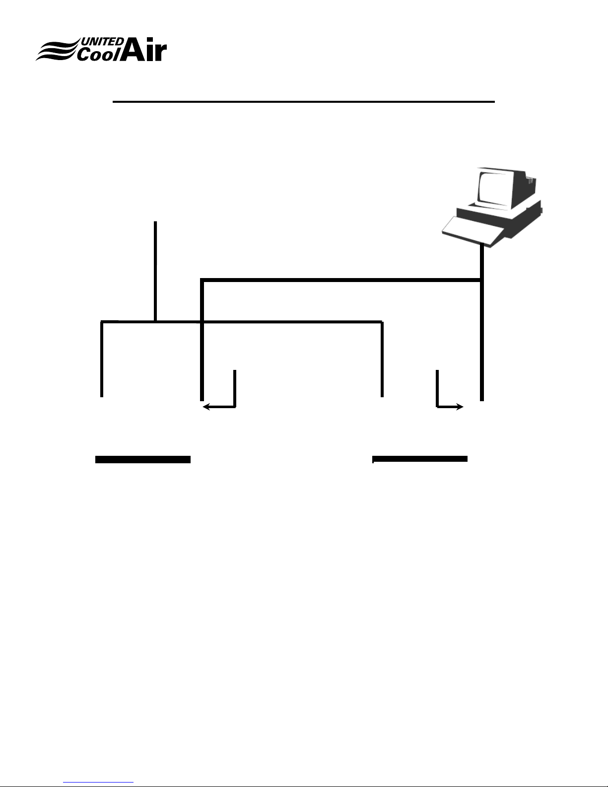
Figure 1 – System Layout is made up of the Marvel Mini™
main control board showing options for communicating
devices, networking, building management and supervisory
system setups. Customers have the option of either a builtin or wall mount display and keypad or even both of these if
desired. The Marvel Mini™ system also contains common
required standard sensors as well as optional sensors that
must be eld installed and wired to the factory provided eld
interface terminal blocks in the air handlers electrical control
box.
Each Marvel Mini™ has numerous standard setups built
for interfacing with ECM Fans and VFDs for low ambient
and duct pressure control and/or Humidier controllers
through serial communication ports saving additional I/O for
system sensors. The Universal Input channels have been
developed so that a customer can replace or add a sensor
in the eld and set up the characteristics of the sensor
under a sensor setup menu however, it is recommended
to contact the local distributor or factory before doing so for
detailed information.
The Marvel Mini™ is equipped with a set of plug in terminal
block connectors used to connect the Main Board to the
controlled devices (i.e. solenoid valves, compressor
contactor(s), blower contactors, heater contactors, VFDs,
etc.). The application program is stored in Flash Memory
of the controller and the unit’s hardware setup and control
set points and parameters are stored in permanent memory
(even in case of power failure). The software program is
designed for “smart control”, to automatically predict and
project required changes based upon present readings over
time intervals in efforts to proactively adjust to changing
conditions. The Marvel Mini™ can be linked with Building
Management Systems RS485 serial or Ethernet connections
with customer provided communication protocol details.
As a standard unless otherwise specied, the Marvel Mini™
microprocessor-based Remote User Terminal unit comes
complete with LCD Display and Keypad for viewing and
setting of the control parameters (set points, proportional
bands, dead bands, and alarm set points, system run hours.
etc.). The Terminal also allows viewing of the operating
parameters, staging of system components, and system
demands. Connection between the Marvel Mini™ main
board and remote user terminal is only required for viewing
or changing of the operating conditions and set points.
Subject to change without notice. 120.9-IM (1218)
3
Page 4

Installation, Operation and Maintenance Manual
Marvel Mini
Marvel Mini™ - Controllable System Component Information
With this new format, one of the key benets of the Marvel Mini™ application software is set up universally so that any of the
following functions could literally be added to any of the corresponding channels. This means for example, any of the listed
functions under Analog/Universal Inputs could be placed onto any of the Universal Channels U1 though U10 whereas in
the past and with most control vendors, a software modication would be required. In addition now all of the Analog Inputs,
Digital Inputs, Analog Outputs, and Digital Outputs are all selectable for any of their corresponding channels. So for instance
the digital output for Compressor 1 could be congured on any of the Digital Outputs NO1 through NO18 (example of large
controller maximum number of Digital Outputs). These Universal Functions for each of the four I/O Groups are:
ANALOG/UNIVERSAL INPUTS
Return Temperature Compressor 1 Liquid Temperature Compressor Liquid Pressure
Space Temperature Compressor 1 Suction Temperature Space Humidity
Outdoor Air Temperature Water Temperature Outdoor Air Humidity
Supply Air Temperature 1 Return Humidity
ANALOG OUTPUTS
Modulating Hot Gas Bypass Modulating Waterside Economizer Discharge Pressure Valve 1
Airside Economizer Modulating Reheat
Modulating Heater Modulating Humidifier
DIGITAL INPUTS
Compressor 1 High Pressure Remote ON/OFF Heater High Limit
Compressor 1 Low Pressure Dirty Filter Water Flow
Loss of Airflow Compressor Freeze Stat Smoke Purge
Drain Pan Overflow Fire/Smoke Alarm Heat Pump Defrost Switch
DIGITAL OUTPUTS
Supply Blower Heater Global Alarm Output
Outdoor/Fresh Air Damper Reversing Valve
Compressor Reheat
Subject to change without notice. 120.9-IM (1218)
4
Page 5

Installation, Operation and Maintenance Manual
Marvel Mini
AVAILABLE FUNCTIONS
The following is a listing of available functions please inquire with the local United CoolAir Distribution for unit design
congurations with these functions:
● One Compressor Staged ON/OFF or Digital.
● One Heater Staged ON/OFF or Modulating or Hot Water Coil or Steam Coil for modulating control
valves at 0-10vdc output.
● Modulating Humidier controlled via Modbus Communications.
● Modulating Hot Gas Bypass for system capacity control.
● Modulating Blower control for Variable Air Volume applications with VFDs communication via
Modbus to display critical information from the VFD to the Display where as previously important
information such as motor current, motor speed, voltage, kw hours was not supplied due to hard wire
congurations.
● Modulating Blower for Variable Air Volume applications via ECM motors.
● Hot Gas Reheat either by Stage or Modulating.
● Compressor safeties for high and low pressure are wired independently for true notication of which
failure High or Low Pressure.
● An Air Switch has been incorporated to turn off cooling, heating, dehumidication, and humidication in
the event of a loss of air ow due to a broken v-belt or other means.
● On a heater high limit failure the heaters are locked out, but automatically reset when the safety resets.
The display and alarm button will indicate an alarm occurred with the heating function.
● Airside or Waterside Economizer.
● Integrated Economizer function that allows Mechanical Cooling Compressors to assist is also available.
● Networking of multiple units with Unit Lead Lag and Backup unit assist is built into the main software
platform so if multiple units are shipped to the eld and the customer decides to network the units
together at a later date the software is already capable of networking up to 16 total units.
● Building Management Systems via the following BMS Protocols is available: BACnetTM Modbus®,
Lonworks®, HTML Web Pages
Subject to change without notice. 120.9-IM (1218)
5
Page 6
HARDWARE AND ARCHITECTURAL LAYOUT
HARDWAREANDARCHITECTURALLAYOUT
Terminal /
Wall Mount
Control
Interface Wiring
Interface
RS485
Installation, Operation and Maintenance Manual
Marvel Mini
Building
Management
System
BMS - Interface
Networking Cable
RS485
Interface
Marvel Premium
Mini Main Board 1
FIGURE 1 – HARDWARE / ARCHITECTURE LAYOUT
Subject to change without notice. 120.9-IM (1218)
6
Marvel Premium
Mini Main Board 2
Page 7

Installation, Operation and Maintenance Manual
Marvel Mini
MARVEL MAIN BOARD
Figure 2 – Marvel Mini™ Main Board is the layout of the main control board. The reference designator Jxx specically lists
the functions of each location on the board. These references are as follows:
FIGURE 2 – MARVEL MAIN BOARD
J1 Control Voltage connection terminals. 24 VAC required.
J2 Universal Inputs used for sensor readings. Each channel can handle any of the Analog/Universal Input
functions.
J3 Used for connecting the Remote Display/Wall Terminal
J4 Fieldbus Device Connections.
J6 BMS Interface RS-485 or Ethernet based on model ordered.
J7 No Function for the Marvel Mini™ controller.
J8 Digital Inputs used for safety and alarm devices and Analog Outputs used for optional modulating devices.
J9 Power supply +5 vdc or +24 vdc to power sensor devices.
J10 Normally Open Digital Outputs 1 and 2.
J11 Normally Open Digital Outputs 3 through 5.
J12 Normally Open/Normally Closed Digital Output 6.
Subject to change without notice. 120.9-IM (1218)
7
Page 8
Installation, Operation and Maintenance Manual
Marvel Mini
MARVEL TERMINAL (WALL CONTROL)
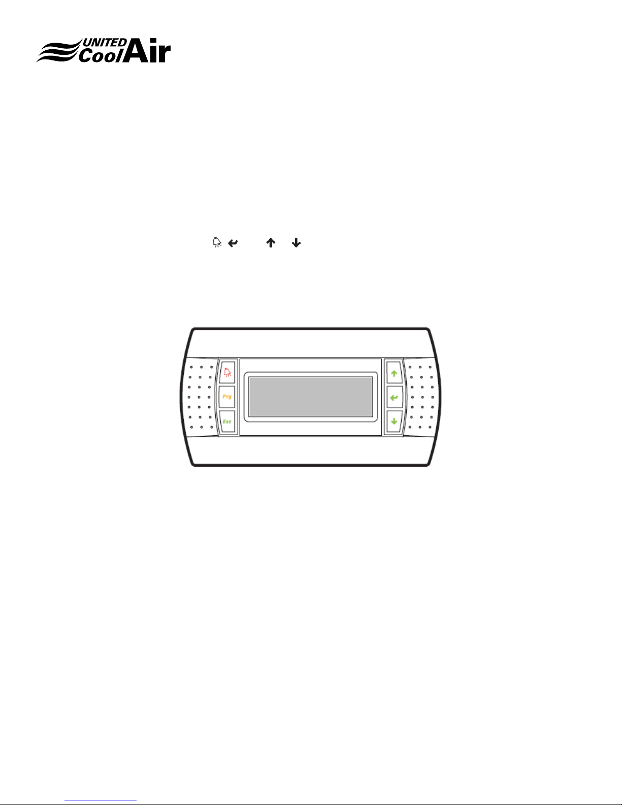
The Marvel Terminal is complete with LCD Display and Keypad. The Terminal has LED indicators integral to the buttons. A
description of each indicator light is discussed with the function of the each button starting on page 11.
The Marvel Terminal contains no sensors and does not need to be located in the building’s space that is being conditioned.
The Terminal can be mounted up to 1000 feet from the equipment. See Figure 3 – Terminal below for reference. The
Terminal is made up of the following components:
A. External buttons Prg, Esc, , , and or (adjustment buttons) with integral LED indicators.
B. Submenus include System ON/OFF, System Status, System Enables, Set Points, Alarm Set Points, Run
Hours, Day Min/Max, Clock Settings, Schedule, Setback, Unocc Control, Change Passwords, Technician
Menu, Factory Menu
C. A 22 character by 8 row LCD Display with English text for ease of understandability for adjustment.
FIGURE – 3 TERMINAL (WALL MOUNT) CONTROL
Subject to change without notice. 120.9-IM (1218)
8
Page 9

MARVEL WALL DISPLAY BUTTONS
See Figure 4 – Control Buttons for reference.
Installation, Operation and Maintenance Manual
Marvel Mini
ALARM BUTTON
PROGRAM BUTTON ENTER BUTTON
ESCAPE BUTTON DOWN BUTTON
UP BUTTON
FIGURE 4 – CONTROL BUTTONS
ALARM BUTTON
The button is used for viewing the present alarms with the system. During an alarm condition, the button is illuminated
a continuous Red. Depending on the type of alarm, the system may shut down or continue to operate. Some types of alarms
are just simple faults known as indicators which are not harmful to the operation of the unit but may require attention in the
near future. Pressing the button will reveal what alarm caused the system to shut down. To reset an alarm, press the
button until the screen displays “NO MORE ALARMS; To reset the alarm, simply press the button again to reset the alarm.
PROGRAM BUTTON
The Prg button is used to enter into menus and sub menus. On controllers with built in displays, the is the program button.
ESCAPE BUTTON
The Esc button is used to return to the main system status from a menu or sub-menu or escape to the previous menu from
a sub-menu. On controllers with built in displays, the is the escape button.
UP BUTTON
The up button is used to scroll upward through status screens, menus, sub-menus and change the value of parameters or
settings.
ENTER BUTTON
Upon application of power to the system, the splash screens appear then the main status home screen will appear. Use the
enter button to move the cursor to the next eld (set points or parameters) where the change is desired. Also use the Enter
button to initialize/save changed parameters and set points into memory.
DOWN BUTTON
The down button is used to scroll downward through status screens, menus, sub-menus and change the value of parameters
or settings.
Subject to change without notice. 120.9-IM (1218)
9
Page 10

Installation, Operation and Maintenance Manual
Marvel Mini
PROGRAMMING AND OPERATING SCREENS
As shown in Figure 4 previous, each of the buttons are used to access specic locations to Read or Change (such as set
point) values. Below is a list of the menus that are accessible from the wall mount controller. By pressing the Prg button
multiple times, the following menus will appear:
4. SET POINTS menu – Used for changing temperature and humidity settings. It is also used to set temperature
high and low alarm set points as well as humidity high and low alarm set points. If customers have the pressure
control option, settings will also appear to adjust duct or room pressure.
5. TIME CLOCK SETTINGS menu – Used for changing the Time Clock Readings to the current Time and Date.
This menu is also used for setup of Daylight Savings Time based on region and enabling of the Night Set Back
Function. Once the Night Set Back Function is enabled, the type of control (Temp/Humidity Setback) is enabled
and Set Points for Temperature and Humidity Setback Control shall appear as well as the day of the week to
enable Night Set Back and time of day for occupied and unoccupied period.
6. SYSTEM ENABLES menu – This sub-menu allows for re-enabling of system functions (System ON/OFF,
Humidication/Dehumidication, Compressors, Heaters, ON/OFF and Modulating Reheat, etc.) after an alarm
condition has occurred.
7. EQUIPMENT RUN HOURS menu – Displays the operational run hours of system components such as Fan,
Humidier, Compressors, Heaters, etc.).
8. ANALOG/DIGITAL INPUTS/OUTPUTS menu – This sub-menu is used to calibrate sensors and alarm input setup
settings.
9. PRG & ESC (Factory Setup menu) – Used for changing the Factory Default System settings. It is used to
change control functions with their equipment.
LCD Display
The Terminal provides eight lines of twenty-two characters per line LCD Display. The character is 5 mm in height. See Figure
5 – LCD Display.
U01 Mon 07:21 03/19/17
Return Hum > 55.0%
Return Temp> 74.7 °F
Supply Temp> 57.2 °F
One Compressor ON
FIGURE 5 – LCD DISPLAY
Subject to change without notice. 120.9-IM (1218)
10
Page 11

Installation, Operation and Maintenance Manual
DISPLAY DIMENSIONS
Refer to Figure 6 – Terminal Dimensions for dimensional data. Dimensions shown are in inches.
Marvel Mini
FIGURE 6 – TERMINAL DIMENSIONS
Marvel Display (Terminal) – Wall Mounting
Refer to Figure 7 – Wall Mounting for instructions to mount the Terminal to a wall.
FIGURE 7 – WALL MOUNTING
Components of the Wall Controller:
A. Faceplate
B. Wall Controller
C. Mounting Plate
Subject to change without notice. 120.9-IM (1218)
11
Page 12

Installation, Operation and Maintenance Manual
Marvel Mini
For best results in mounting of the wall controller, obtain an single position Receptacle/Switch Electrical Box which typically
measures approximately 3.75” high x 2.25” wide x 2.83” deep. Install the box sideways (90 degrees) internal to the wall
from the original upright position. The box may be installed on metal or wood studded framing. Route the eld provided
connecting cable to the box.
1. Remove the Faceplate “A” from the Wall Controller.
2. Using a small straight screw driver, remove the two screws which secure the Wall Controller “B” to the Mounting
Plate “C”.
3. Route the connector/cable through the back of the Mounting Plate “C” then screw the mounting plate to the
electrical box.
4. Plug the eld provided Connecting Cable to the Wall Controller “B” then reinstall the Wall Controller “B” back onto
the Mounting Plate “C”.
5. Connect the eld supplied standard phone cable into the coupler at the Main Board end.
Subject to change without notice. 120.9-IM (1218)
12
Page 13

Installation, Operation and Maintenance Manual
Marvel Mini
CONNECTING CABLE
The Marvel Terminal (Wall Control) connects to the Marvel
Main Board using a factory provided 100-foot phone cable.
Install the factory supplied 6-conductor cable from the
Marvel Main Board located inside the control box to the
location the Marvel Terminal shall be installed.
CAUTION: The factory provided is a special cable. If
longer or shorter cable is desired, please contact the local
Distributor for a longer/shorter length making sure to provide
the desired length. NEVER ATTEMPT TO LENGTHEN THE
FACTORY SUPPLIED CABLE as this cable specic pin
connections. The Marvel Terminal will not work if the pin
terminations are not correct and may damage the Marvel
Main Board or blow the fuse due to improper connections.
SENSOR INSTALLATION AND
ELECTRICAL TERMINATIONS
ELECTRICAL CONNECTIONS
All electrical wiring must be in accordance with NEC
(National Electrical Code)/NFPA (National Fire Protection
Agency), as well as state and, local building codes. Refer to
the specications section or the unit’s data tag for the unit’s
power requirements.
SERVICE DISCONNECT
A eld installed fused single point power service disconnect
is required. Install the service disconnect in accordance
with NEC, State, and Local building codes. NEC guidelines
require the unit’s disconnect be installed within sight of the
unit.
A factory provided power block is installed internal to the
unit’s electrical control panel. Route the main power wires
in accordance with electrical codes to the eld provided unit
service disconnect and terminate them on the line side of
the disconnect. Route the power wires from the Load side
of the eld provided service disconnect to unit power block
inside the electrical control panel.
A ground termination point is located within the unit’s
electrical control panel. All units must have a hard wired
ground from a source Earth Ground.
IMPORTANT: Metal Conduit is not an acceptable source
of ground as there may be air gaps between
connection points.
SENSOR FIELD MOUNTING & WIRING
All sensors and optional components that must be eld
installed and wired to the electrical control panel must be
wired as shown on the electrical diagram provided with
the unit. The installation instructions correspond with the
electrical diagram for the eld installable components.
For special order options which are not listed within these
sensor installation instructions, please refer to unit’s factory
provided electrical diagram and the installation instructions
provided with each component for proper installation
requirements.
Static Pressure Transducer
(Duct Mount)
Mounting
The static pressure transducer shown in Figure 8 – Pressure
Transducer must be installed in the main supply air ducting
at a location approximately two-thirds of the distance down
the straightest duct run from the supply air outlet of the unit.
The location must be a non-turbulent area of supply air ow.
Mount the pressure transducer as follows:
1. Remove the pressure transducer’s cover plate screws
using a Phillips head screw driver.
2. Select the mounting location. Install the sensor at the
approximate mid-point/center of the vertical plane of
the ducting.
3. The sensor must be mounted vertically with the
electrical entrance/strain relief facing downward.
4. Drill a ½” hole through the face of the duct.
5. Before installing the duct pressure transducer, make
sure the gasket at the base where the duct probe
meets the transducer housing is intact and sealed to
the sensor (so that it will seal the perimeter of the hole
drilled).
6. Insert the probe into the duct and mount the pressure
transducer using two (2) eld provided #8 sheet metal
screws.
Wiring
Using a minimum 18-20 AWG 300 volt rated two conductor
shielded cable with drain wire make the following electrical
connections.
Subject to change without notice. 120.9-IM (1218)
13
Page 14
Installation, Operation and Maintenance Manual
Marvel Mini
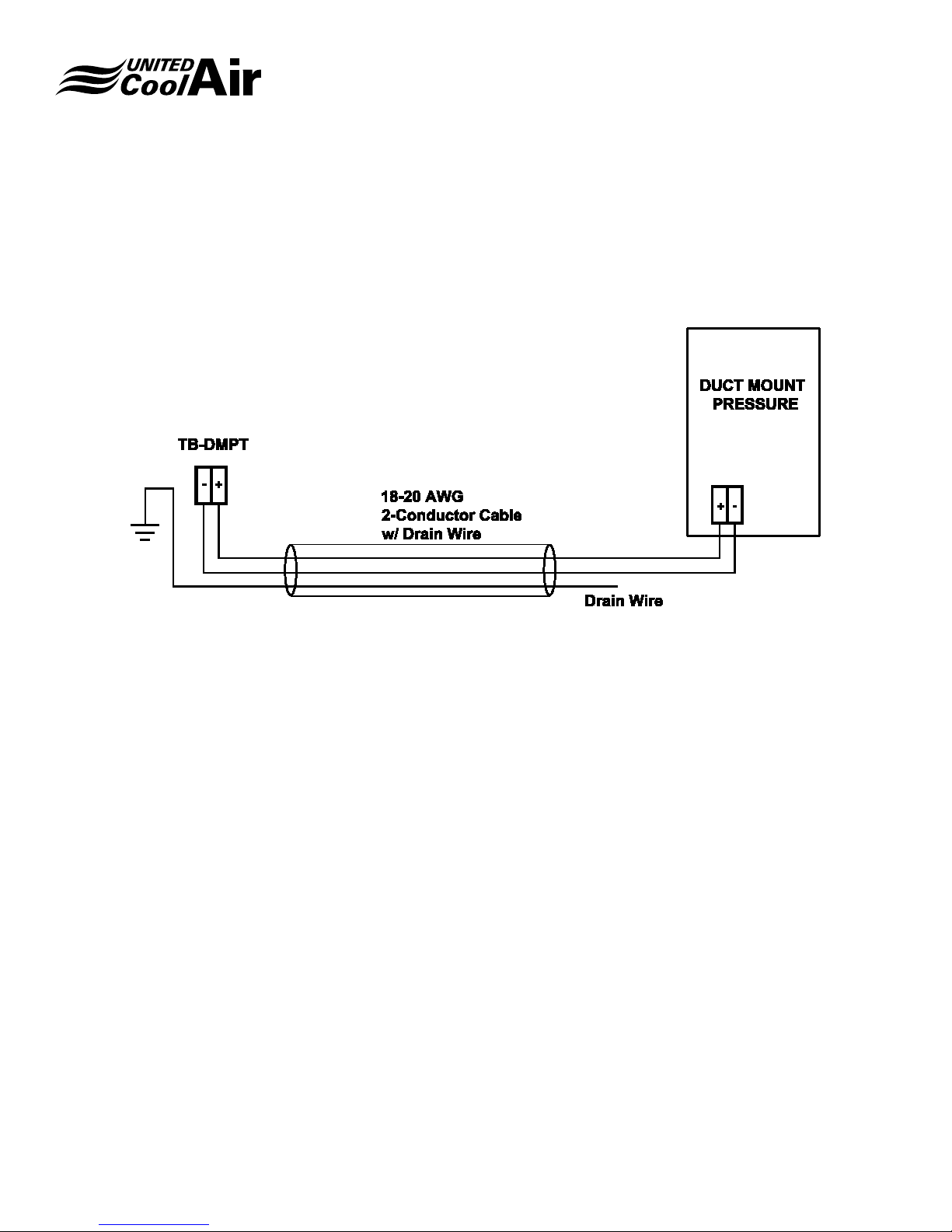
IMPORTANT: Please observe polarity of this sensor. The “+”
is +24 vdc and the “–“ is the output (4-20 mA)
to the Analog Input of the controller.
7. Connect from the positive terminal “+” inside the
pressure transducer to the unit’s electrical terminal
block TB-DMPT +.
FIGURE 8 – PRESSURE TRANSDUCER
8. Connect from the negative terminal “–” inside the
pressure transducer to the unit’s electrical terminal
block TB-DMPT –.
9. Connect the drain wire to ground at the unit end only.
The factory provided static pressure transducer is preset
for application requirements. The unit’s controller will read
the preset conguration. If a higher or lower pressure
conguration is required, use the manufacturer’s provided
literature to re-congure the sensor to read the desired
lower or higher pressure setting.
NOTE: When changing the conguration of the pressure
transducer, the range for the sensor must also be changed
within the unit’s controller/sensor setup area. Refer to the
Marvel Controller’s Technician’s Menu – Sensor Setup area
for setting up the range of the sensor.
Duct Mount Supply Air Temperature Sensor
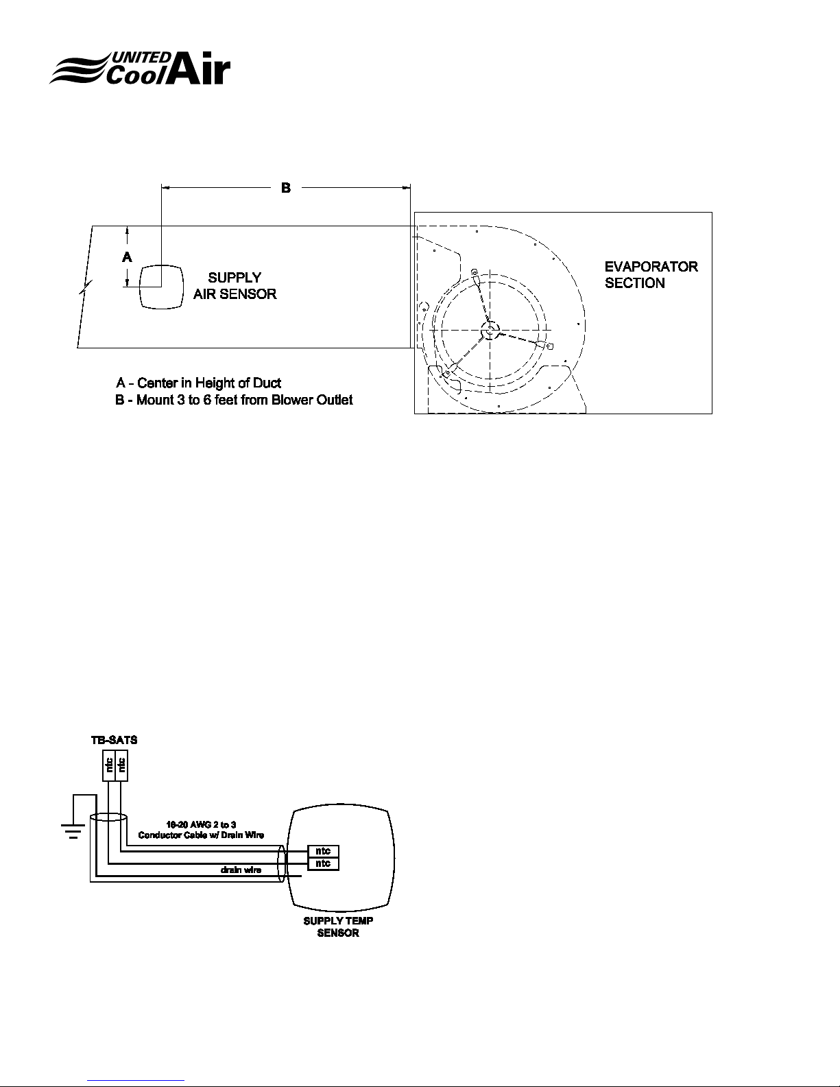
The duct mount supply air temperature sensor(s) shown
in Figure 9 – Supply Air Sensor must be eld installed in
the supply air ducting. The location of the sensor must be
relatively close to the duct pressure transducer and must
not impede with airow to the inlet of the transducer. A few
feet (2/3 feet) from the transducer is recommended.
Mounting
1. Cut out the mounting template provided with the
sensor.
2. Select the location to mount the sensor and drill a hole
through the supply air duct at least ¾” in diameter.
3. Using a 7/64” drill-bit, drill the three fastening screw
holes located on the template for the fastening ring.
4. Remove the duct sensor’s mounting ring from the duct
probe being careful not to lose the sealing gasket.
5. Position the mounting ring over the ¾” hole drilled in
step 2.
6. Use three (3) eld provided #6 x ¾” Pan Head sheet
metal screws and fasten bracket to the duct.
7. Place the probe through the mounting bracket and into
the supply air duct.
8. Using the screw provided with the sensor installation
kit, place the screw into the clamping ring and tighten
the ring to secure the sensor to the clamping ring.
Subject to change without notice. 120.9-IM (1218)
14
Page 15
Installation, Operation and Maintenance Manual
FIGURE 9 – SUPPLY AIR SENSOR
Marvel Mini
Wiring
Figure 10 – Supply Air Sensor Wiring shows how the sensor
is wired. Using a minimum 18-20 AWG 300 volt rated two
conductor shielded cable with drain wire make the following
electrical connections. The supply air temperature sensor is
non-polarity observant.
1. Connect from one NTC terminal inside the supply air
temperature sensor to terminal block TB-SATS – NTC
inside the unit’s electrical control box.
2. Connect the other NTC terminal inside the supply air
temperature sensor to terminal block TB-SATS – NTC
inside the unit’s electrical control box.
3. Connect the drain wire to ground inside the unit’s
electrical control box.
FIGURE 10 – SUPPLY AIR SENSOR WIRING
Duct Mount Return Air Temperature Sensor (Optional
Humidity)
The return air temperature sensor shown in Figure 11 –
Return Air Sensor must be eld installed in the return air
ducting close to the unit. The return air sensor must be
located relatively close to the Filter Rack of the unit.
IMPORTANT: If the unit has optional humidity control,
please observe when making electrical connections.
Mounting
1. Cut out the mounting template provided with the
sensor.
2. Select the location to mount the sensor and drill a hole
through the supply air duct at least ¾” in diameter.
3. Using a 7/64” drill bit; drill the three fastening screw
holes located on the template for the fastening ring.
4. Remove the duct sensor’s mounting ring from the duct
probe being careful not to lose the sealing gasket.
5. Position the mounting ring over the ¾” hole drilled in
step 2.
6. Use three (3) eld provided #6 x ¾” Pan Head sheet
metal screws and fasten bracket to the duct.
7. Place the probe through the mounting bracket and into
the supply air duct.
8. Using the screw provided with the sensor installation
kit, tighten the clamping ring.
Subject to change without notice. 120.9-IM (1218)
15
Page 16
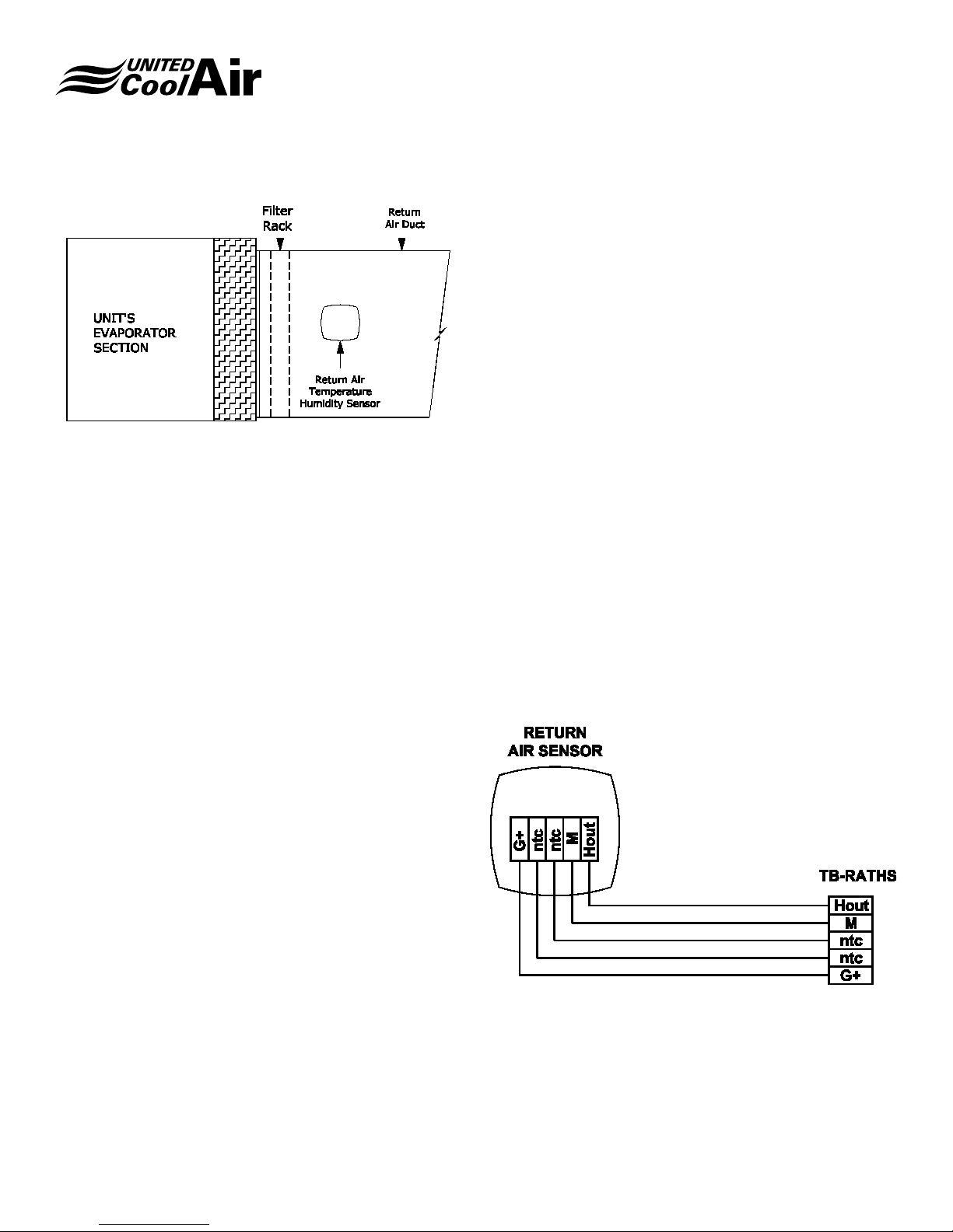
NOTES: 1. Return Temp & RH Sensor is Factory Provided &
Field Installed.
FIGURE 11 – RETURN AIR SENSOR
Wiring
Figure 12 – Return Air Temperature/Humidity Sensor Wiring
shows how the sensor is wired. Using a minimum 18-20
AWG 300 volt rated two conductor shielded cable with drain
wire make the following electrical connections.
NOTE: Use a minimum two conductor cable for temperature
only. Use a minimum ve conductor for temperature
and humidity control.
1. The return air temperature sensor is non-polarity
observant.
2. Connect from one NTC terminal inside the return air
temperature sensor to TB – RATS - NTC.
3. Connect the other NTC terminal inside the temperature
sensor to TB – RATS - NTC.
4. Connect the drain wire to ground at the unit’s electrical
control panel end only.
Installation, Operation and Maintenance Manual
Marvel Mini
FIGURE 11.5 – CONNECTING THE TERMINAL
Optional Humidity Control
If the sensor for Return Air has the optional humidity sensor,
continue with steps 7, 8, and 9.
7. Connect from the terminal marked G+ inside the
sensor to terminal TB-RATHS – G+ inside the unit’s
electrical box.
8. Connect from the terminal marked M inside the sensor
to terminal TB-RATHS – M inside the unit’s electrical
control box.
9. Connect from the terminal marked Hout inside the
sensor to terminal TB-RATHS – Hout inside the unit’s
electrical control box.
c.pCOmini
Use the accessory cable P/N S90CONN0S0, connected
as shown in the gure. The maximum distance allowed
between controller and terminal is 10 m.
Subject to change without notice. 120.9-IM (1218)
FIGURE 12 – REUTRN AIR TEMPERATURE/HUMIDITY
SENSOR WIRING
(Example shown with TB-RATHS humidity connections
option)
16
Page 17

Installation, Operation and Maintenance Manual
Marvel Mini
Room/Space Wall Mount Temperature and
Optional Humidity Sensor
The room temperature with humidity sensor option must be
eld installed in the room being conditioned. Never install
the sensor at a location that can be inuence by solar gain
such as sunlight or by drafts such as doors opening/closing
or direct movement of conditioned air such as from supply
air outlet grills. The location of this sensor should be reading
mixed air, which means the best location should be close to
a return air grille. The installation height should be between
40” to 60” above the room’s oor.
BE AWARE: If the unit has optional humidity control, polarity
must be observed when making electrical
connections.
NOTE: Use a minimum two-conductor cable for temperature
only. Use a minimum ve conductor for temperature
and humidity control. It may be required to preinstall
this wire (addition of drywall, paneling, ceilings, etc.)
if the interior room shall be completed before this
sensor will be installed. If the interior is complete,
install the cable as required being careful not to
damage the cable during installation.
Mounting
1. Cut out the mounting template provided with the
sensor.
2. Select the location to mount the sensor and drill the
appropriate size holes (for the factory supplied wall
anchors) into the surface the sensor is being installed
on.
3. Install the wall anchors as required for installation of
the sensor.
4. Drill a through hole approximately 3/8” to 1/2” in
diameter for the cable as required.
5. Place the cable through the back of the sensor.
6. Using the screws provided, screw the sensor to the
wall.
Wiring
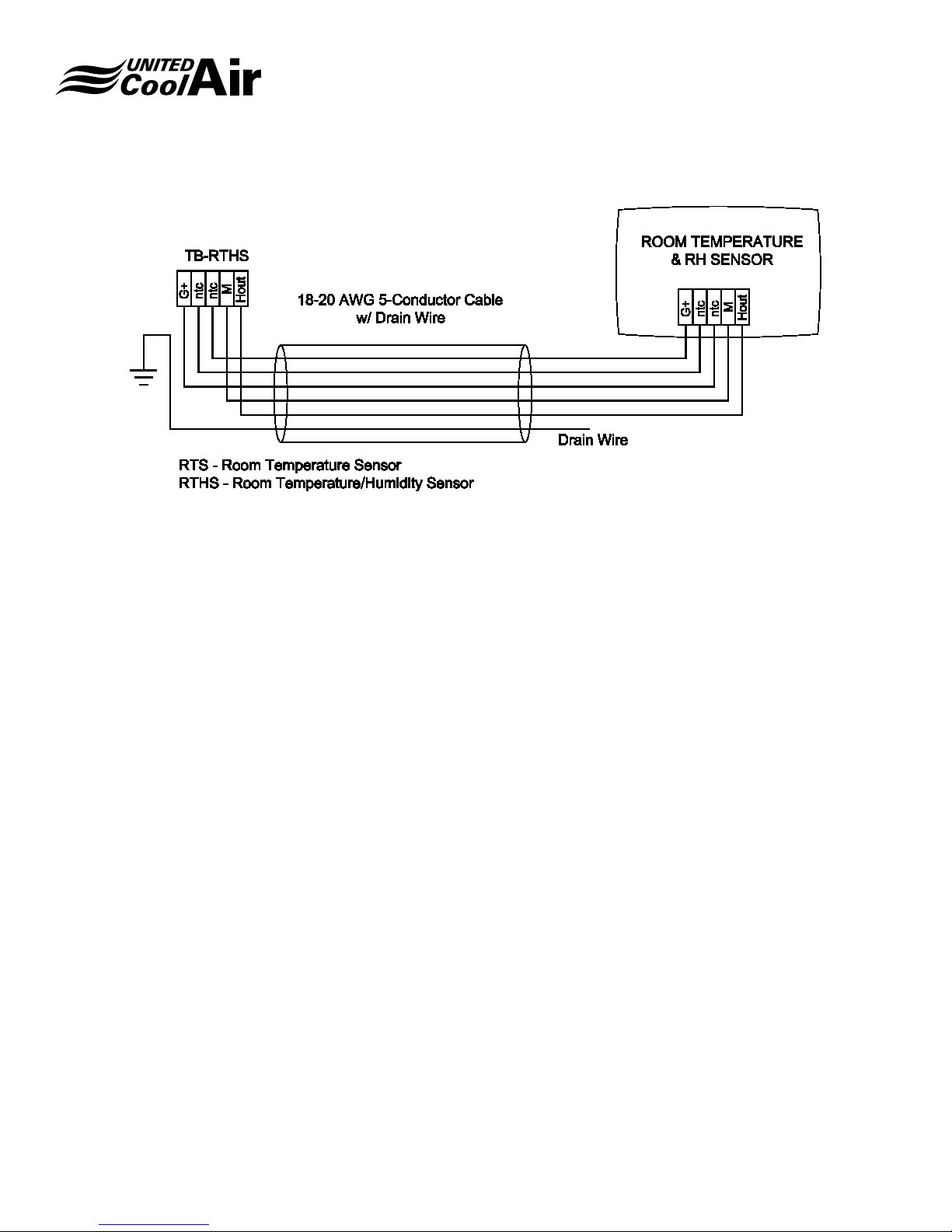
Figure 13 – Room Temperature Humidity Sensor Wiring
shows the electrical connections for the sensor. Using
a minimum 18-20 AWG 300 volt rated two conductor
shielded cable with drain wire make, the following electrical
connections.
NOTE: Use a minimum two-conductor cable for temperature
only. Use a minimum ve conductor for temperature
and humidity control.
1. The room air temperature sensor is non-polarity
observant.
Room/Space Wall Mount Temperature
Sensor Only
2. Connect from one NTC terminal inside the room
air temperature sensor to TB-RTS – NTC (room
temperature only)
3. Connect the other NTC terminal inside the room
air temperature sensor to TB-RTS – NTC (room
temperature only).
Or
Room/Space Wall Mount Temperature /
Humidity Sensor
4. Connect from one NTC terminal inside the room
temperature/humidity sensor to TB-RTHS – NTC
(room temperature and humidity sensor)
5. Connect the other NTC terminal inside the room
temperature/humidity sensor to TB-RTHS – NTC
(room temperature and humidity sensor).
6. Connect the drain wire to ground at the unit’s electrical
control panel end only.
Optional Humidity Control
If the Room Temperature and Humidity Sensor for Room
Air has the optional humidity sensor, continue with steps 7,
8, and 9.
7. Connect from the terminal marked G+ inside the
sensor to terminal TB-RTHS – G+ inside the unit’s
electrical box.
8. Connect from the terminal marked M inside the sensor
to terminal TB-RTHS – M inside the unit’s electrical
control box.
9. Connect from the terminal marked Hout inside the
sensor to terminal TB-RTHS – Hout inside the unit’s
electrical control box.
Subject to change without notice. 120.9-IM (1218)
17
Page 18
Installation, Operation and Maintenance Manual
FIGURE 13 – ROOM TEMPERATURE HUMIDITY SENSOR WIRING
Marvel Mini
(Example shown with TB-RTHS humidity connections
option)
Duct Mount Outdoor Air Temperature
Sensor
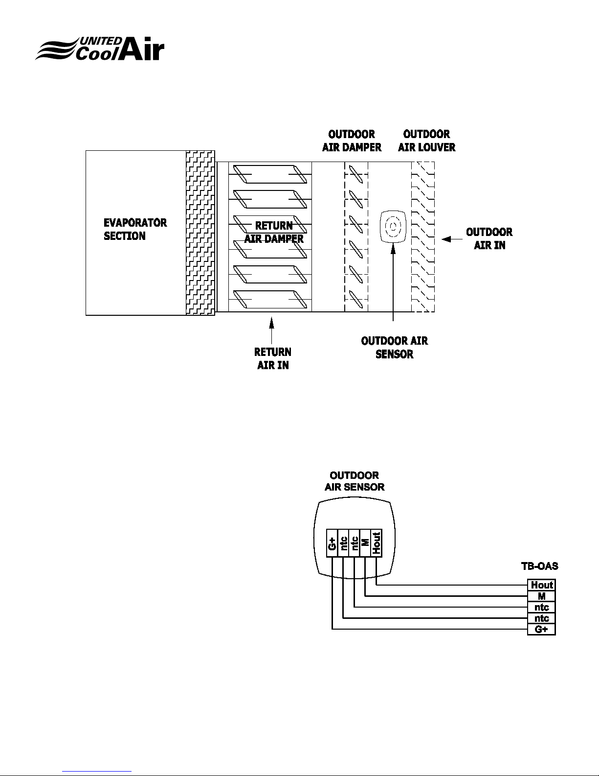
The duct mount outdoor air temperature sensor shown in
Figure 14 – Outdoor Air Temperature / Humidity Sensor
must be eld installed in the outdoor air ducting close to an
outdoor air louver but back inside of the ducting far enough
that it does not rain onto the sensor. It should also be located
before the outdoor air inlet damper in order to always
monitor the outdoor air temperature and humidity correctly
unless the unit will always be providing a minimal amount of
outdoor air when occupied (in this case the sensor could be
located between the outdoor air louver and the unit).
IMPORTANT: If the unit has humidity control for airside
economizer, polarity must be observed when making
electrical connections.
1. Cut out the mounting template provided with the
sensor.
2. Select the location to mount the sensor and drill a hole
through the supply air duct at least ¾” in diameter.
3. Using a 7/64” drill bit; drill the three fastening screw
holes located on the template for the fastening ring.
4. Remove the duct sensor’s mounting ring from the duct
probe being careful not to lose the sealing gasket.
5. Position the mounting ring over the ¾” hole drilled in
step 2.
6. Use three #6 x ¾” Pan Head sheet metal screws and
fasten bracket to the duct.
7. Place the probe through the mounting bracket and into
the supply air duct.
8. Using the screw provided with the sensor installation
kit, tighten the clamping ring.
Subject to change without notice. 120.9-IM (1218)
18
Page 19
Installation, Operation and Maintenance Manual
Marvel Mini
FIGURE 14 – OUTDOOR AIR TEMPERATURE / HUMIDITY SENSOR
Wiring
Using a minimum 18-20 AWG 300 volt rated two conductor
shielded cable with drain wire make the following electrical
connections. Use a minimum ve conductor for temperature
and humidity control. Refer to Figure 15 – Outdoor
Temperature/Humidity Sensor Wiring.
1. The return air temperature sensor is non-polarity
observant.
2. Connect from one NTC terminal inside the outdoor
temperature/humidity sensor to TB-OTHS – NTC.
3. Connect the other NTC terminal inside the outdoor
temperature/humidity sensor to TB-OTHS – NTC.
4. Connect the drain wire to ground at the unit’s electrical
control panel end only.
5. Connect from the terminal marked G+ inside the
outdoor temperature/humidity sensor to terminal TBOTHS – G+ inside the unit’s electrical box.
6. Connect from the terminal marked M inside the
outdoor temperature/humidity sensor to terminal TBOTHS – M inside the unit’s electrical control box.
7. Connect from the terminal marked Hout inside the
outdoor temperature/humidity sensor to terminal TBOTHS – Hout inside the unit’s electrical control box.
FIGURE 15 – OUTDOOR TEMPERATURE/HUMIDITY
SENSOR WIRING
Subject to change without notice. 120.9-IM (1218)
19
Page 20

Installation, Operation and Maintenance Manual
Marvel Mini
Remote Alarm Output Option
On systems without BMS Communications, an option can
be provided for Remote/Global Alarm Output, which closes
a set of voltage free dry contacts on global alarm to terminals
TB-RA – 1 and TB-RA – 2. With this option, look for terminal
block TB-RA. The device must not exceed 10 amps at 240
VAC or 10 Amps at 24 VDC. Install two conductors 14 – 18
AWG 600 volt rated from the Remote Alarm device to the
unit’s terminal blocks TB-RA. Whether connecting a buzzer
or an indicator light, the device must have a separate power
source. Determine which side of the device to disconnect
(hot or common/neutral) through the factory provided dry
contact terminal blocks and wire as follows:
Wiring the Remote/Global Alarm Output
1. Remove one wire from the Coil of the Alarm Device
and wire nut or splice cap this wire with one of the two
wires going to the Remote Alarm interlock wiring.
2. Connect the other wire of the Remote Alarm interlock
wiring to the location of the wire removed from Remote
Alarm device.
3. At the unit, connect one wire to terminal TB-RA – 1.
4. Connect the other wire to TB-RA – 2.
3. At the unit, connect one of the wires to TB-WP – 1.
4. Connect the other wire to TB-WP – 2.
Optional Airside Economizer Damper
Control
If the customer’s system has optional Airside Economizer
Dampers that must be modulated for free cooling, the
terminal blocks for interlocking this function are TB-ASE –
1, TB-ASE – 2, and TB-ASE – 3. Install three conductors
16 – 18 AWG minimum 300 volt rated from the Airside
Economizer Damper Actuators’ location to the unit’s terminal
blocks TB-OAD.
Connect the wires as follows:
Wiring of the Airside Economizer Damper
Actuators
1. Connect the Common wire at the Damper Actuator to
terminal TB-ASE – 1 inside the unit’s electrical box.
2. Connect the 24 vac wire at the Damper Actuator to
terminal TB-ASE – 2 inside the unit’s electrical box.
3. Connect the 0-10 vdc wire at the Damper Actuator to
terminal TB-ASE – 3 inside the unit’s electrical box.
Remote Water Pump ON/OFF Option
If the customer’s system has an ON/OFF Water Pump that
must be commanded on when there is a call for cooling,
and the unit has the optional Remote Water Pump ON/
OFF terminal blocks, the terminal blocks for interlocking
this function are TB-RWP – 1 and TB-RWP – 2. Determine
whether the Hot or Common/Neutral shall be wire through
the contacts for Remote Water Pump interlock. Next,
install two conductors 14 – 18 AWG 600 volt rated from
the Remote Water Pump’s Contactor/Starter location to
the unit’s terminal blocks TB-RWP. Connect the wires as
follows:
Wiring at the Pumps Contactor/Starter
1. Remove one wire from the Coil of the Water Pump’s
Contactor/Starter and wire nut or splice cap this wire
with one of the two wires going to the Remote Water
Pump interlock wiring.
2. Connect the other wire of the Remote Water Pump
interlock wiring to the location of the wire removed
from the Contactor/Starter Coil.
Optional Outdoor Air Damper Control
If the customer’s system has an Outdoor/Fresh Air Damper
that must be opened or closed by the unit during system
start and occupancy schedule, the terminal blocks for
interlocking this function are TB-OAD – 1 and TB-OAD –
2. Determine whether the Hot or Common/Neutral shall be
wired through the contacts for Outdoor Air Damper interlock.
Next, install two conductors 16 – 18 AWG minimum 300 volt
rated from the Outdoor Air Damper Actuator’s location to
the unit’s terminal blocks TB-OAD. Connect the wires as
follows:
Wiring at the Outdoor Air Damper
1. Connect the Common wire at the Damper Actuator to
terminal TB-OAD – 1 inside the unit’s electrical box.
2. Connect the 24 vac wire at the Damper Actuator to
terminal TB-OAD – 2 inside the unit’s electrical box.
Optional Smoke Detector
If the factory ordered smoke detector option is provided,
four terminations shall be required. Follow the installation/
Subject to change without notice. 120.9-IM (1218)
20
Page 21

Installation, Operation and Maintenance Manual
Marvel Mini
mounting instructions provided with the device. Install a
four conductor cable minimum 18 AWG 300 volt rated from
the smoke detector to the terminal blocks labeled TB-SD
provided inside the unit.
Wiring
1. Terminate from the device terminal number 9 to the
factory provided terminal TB-SD – 9.
2. Terminate from the device terminal number 10 to the
factory provided terminal TB-SD – 10.
3. Terminate from the device terminal number 6 to the
factory provided terminal TB-SD – 6.
4. Terminate from the device terminal number 16 to the
factory provided terminal TB-SD – 16.
On units with both a supply and return smoke detectors,
these terminals shall have terminal designations of TB-SSD
for Supply Smoke Detector and TB-RSD for Return Smoke
Detector instead of TB-SD. The terminal number pattern is
the same. Terminal 9 inside the Smoke Detectors terminate
to terminal 9, 10 inside the smoke detector terminates to 10
inside the unit and so on. The only difference is the location
of the smoke detectors (supply or return air streams). Please
remember to account for this during installation.
Optional Fire Stat Terminations
For a Field Supplied Fire Stat, two terminations shall be
required. Follow the installation/mounting instructions
provided with the device. Install a two-conductor cable
minimum 18 AWG 300 volt rated from the smoke detector/
re stat to the terminal blocks provided inside the unit.
Wiring
1. Locate the Normally Closed dry contact terminations,
which open on alarm, inside of the Firestat.
2. Terminate from one of the terminals inside of the Fire
Stat to the factory provided terminal TB-FS – 1.
3. Terminate from the other terminal inside of the Fire
Stat to the factory provided terminal TB-FS – 2.
Optional Remote On/Off Control
With the optional Remote On/Off Control, the unit will start
when a voltage free dry contact closure is provided to
Terminals TB-RMTO – 1 and TB-RMTO – 2. This closure
should be provided by a dry contact closure switch installed
at a remote location. Install two conductors minimum 18
AWG 300 volt rated from the Remote ON/OFF Switch
location to the unit’s terminal blocks TB-RMTO. Connect
the wires as follows:
Wiring
1. Connect one wire at the Remote ON/OFF switch to
one termination pole of the switch.
2. Connect the other wire of the Remote ON/OFF switch
to the other termination pole of the switch.
3. At the unit, connect one of the wires to TB-RMTO – 1.
4. Connect the other wire to TB-RMTO – 2.
MARVEL MULTIAPP CONTROLLER –
SEQUENCE OF OPERATION
Outdoor Air Damper (option)
On units without the Airside Economizer option, the system
has an option for a Fresh Air Damper Output. If the Fresh Air
Damper Output is enabled and the system is in the Occupied
Mode, the output will open the outdoor air damper once the
System ON/OFF is set to the ON position. After the initial
startup delay of 5 seconds (default and eld adjustable),
the output for the fresh air damper will supply a dry contact
closure to start the Fresh Air Damper. This option allows the
damper to drive open based on two methods.
1. Outdoor Air Damper Time Delay – Allows the Outdoor
Air Damper to drive open for the adjustable damper
time delay before starting the Supply Air Blower.
2. Outdoor Air Damper End Switch – Allows the Outdoor
Air Damper to drive open but will not start the unit’s
Supply Air Blower(s) until the Outdoor Air Damper End
Switch provides contact closure back to the Marvel
Multi-Application controller verifying that the Outdoor
Damper is open.
Outdoor Air Damper End Switch (option)
On units with the optional Outdoor Air Damper End Switch
enabled, the Marvel Multi-Application Controller will not
start the Supply Air Blower until there is contact closure
on the Outdoor Air Damper End Switch proving that the
Outdoor Air Damper is open. If the controller does not
receive proof that the outdoor air damper is open within the
specied adjustable time delay, the Marvel Multi-Application
controller will provide and Alarm to alert personnel that the
Outdoor Air Damper failed to open.
Subject to change without notice. 120.9-IM (1218)
21
Page 22

Installation, Operation and Maintenance Manual
Marvel Mini
Supply Air Blower
Once the Outdoor Air Damper is open either by time delay
timeout or by proof of the damper end switch contact closure,
the controllers blower output for the Supply Air Blower
energize the blower contactor for the Supply Air Blower
Motor. During the Occupied Mode, the blower will operate
continuously unless the system is set to operate based on
system demands (Cooling, Heating, Dehumidication, or
Humidication). The unit controller has a selection to set
the blower(s) to operate solely based on System Demands
(Cooling, Heating, Dehumidication, or Humidication) only
on units with Constant Air Volume and non-Outdoor Air
systems.
Supply Air Blower – Variable Air Volume
(option)
Once the Outdoor Air Damper is open either by time delay
timeout or by proof of the damper end switch contact
closure, the output for the Supply Air Blower is energized
to the Variable Frequency Drive (VFD). The supply air
blower will provide a percentage of air volume based on
change in duct pressure. As the duct static pressure falls
due to VAV boxes connected to tenant occupied spaces
opening for their requirement to provide conditioned air,
the controller will increase the output demand to the VFD
causing the Supply Air Blower(s) to speed up thus providing
an increase in airow. As tenant occupied VAV boxes close
requiring less conditioned air, the duct static pressure starts
to increase causing the controller to decrease the output
demand to the VFD which slows down the speed supply air
blower(s).
Upon startup of the Supply Air Blower the blower(s)
will ramp to the Minimum Speed (eld adjustable set to
18 Hertz default) set into the Marvel Multi-Application
controller provided for the VFD. After a Sixty (60) second
eld adjustable time delay the VFD starts to follow the
static pressure demand to increase (increase on startup)
or decrease based on the Static Pressure Set Point 1.00
inches of water column (iwc) (default but eld adjustable).
As the Duct Static Pressure increases or decreases above
or below the Duct Pressure Set Point ± the Duct Pressure
Proportional Band Set Point 0.2 iwc (default but eld
adjustable) the controller starts to increase or decrease
the output demand to the VFD causing the blower to speed
up or slow down. If the Duct Pressure is within the Duct
Pressure Dead Band Set Point range Duct Pressure Set
Point and Duct Pressure Dead Band Set Point ±0.15 iwc
there is no output adjustment the VFD so the blower speed
will remain constant.
On units with Electronically Commutated Blower Motors,
the output adjustment is the same only without the VFD
interface since Electronically Commutated Motors have
motor speed control built directly into the housing of the
motor. Duct pressure is maintained by regulating the speed
of a supply air blower by increasing or decreasing the
demand to the Electronically Commutated “EC” Motor to
increase or decrease the blower speed.
Room Pressure Control (option)
Typical applications for this type of control are Clean
Rooms and Isolation Rooms. Room Pressure Control is
an option designed to maintain the air pressure within a
room at a Room Pressure Set Point. This option requires
a factory provided wall mountable, eld installed, pressure
transducer to monitor air pressure within the room being
controlled against any adjoining room(s). The room
pressure is then maintained as close to the pressure set
point as possible using factory or eld provided damper and
damper actuators.
When the Room Pressure rises above the Room Pressure Set
Point plus Room Pressure Band Set Point, the controller will
modulate eld provided-eld installed damper(s) actuator(s)
closed until the Room Pressure Set Point is achieved. If the
Room Pressure falls below the Room Pressure Set Point,
the controller will modulate the damper(s) actuator(s) open
to increase the room pressure until the room pressure set
point is achieved.
Airside Economizer Mode (option)
Airside Economizer is an optional feature for free cooling
that requires a factory-provided duct mount type, eld-
installed, Outdoor Air Temperature and Humidity sensor,
a factory provided wall or duct mountable Return Air
Temperature and Humidity sensor, and a factory supplied
duct mount Supply Air or Mixed Air Temperature sensor.
With the Airside Economizer Option, there is a minimum
damper position set point to maintain a minimum amount of
fresh outdoor air based on regional code requirements. Also
with the Airside Economizer Option, there is a maximum
damper position set point to maintain a maximum amount of
outdoor air based on maximum outdoor air and airow limits
required. The minimum and maximum outdoor air damper
set points are eld adjustable under the Technician Menu -
Economizer Setup.
Subject to change without notice. 120.9-IM (1218)
22
Page 23

Installation, Operation and Maintenance Manual
Marvel Mini
If the Cooling Demand rises above minimum damper
position set point, and the Outdoor Air Enthalpy is less than
the Return Air Enthalpy, and the Outdoor Air Temperature
is below the Outdoor Air Temperature Set Point minus
the Outdoor Air Temperature Band Set Point, the unit will
perform Airside Economizer mode of operation. The amount
of demand for Airside Economizer can be viewed by looking
at the System Demands screen for Air Side Economizer x%.
When operating in airside economizer mode, the outdoor air
dampers are modulated to the position that the Economizer
demand is calling for. If the outdoor air temperature is
less than the Mixed/Supply Air Temperature Set point, the
system will regulate the Outdoor and Return Air Dampers
to maintain the Mixed Air/Supply Air Temperature Set point.
Waterside Economizer Mode (option)
Waterside Economizer Mode is an option available for a
more energy efcient method of cooling when customers
have cooling towers available that can periodically supply
water at a temperature of 55.0°F or lower. The Waterside
Economizer option requires a factory-provided, factoryinstalled, water temperature sensor to monitor the inlet water
temperature to the unit. If the entering water temperature is
below the Water Temperature Set Point minus the Water
Temperature Band Set Point, the controller regulates the
water valve position in an effort to maintain the cooling set
point.
Waterside Economizer Mode will stop when the Cooling
Demand is 0% or the entering water temperature rises
above the Water Temperature Set Point plus the Water
Temperature Band Set Point. When the Water Temperature
rises above the Water Temperature Set Point plus the Water
Temperature Band Set Point and there is still a demand for
cooling, the unit will revert back to mechanical cooling with
compressors to provide the required cooling to meet the
cooling demand.
Waterside Economizer plus Mechanical
Cooling Assist (option)
The Mechanical Cooling plus Waterside Economizer
Assist option follows the same sequence of operation as
the Waterside Economizer option. If the customer selects
the Waterside Economizer plus Mechanical Cooling Assist
Option, the water piping shall be piped internally so that
mechanical cooling will be able to assist the waterside
economizer operation. The controller shall be enabled for
the mechanical cooling assist option. The Compressors
will be staged when the Waterside Economizer Demand is
equal to 100% for greater than the Economizer Assist (eld
adjustable) time delay. The amount of compressors shall be
limited based on the water temperature.
Chilled Water Mode (option)
Should the system have the Chilled Water Mode option, the
control valve for chilled water mode could be either ON/OFF
or Modulating depending on customer preference at the
time of order. If the Chilled Water Valve is ON/OFF (open/
close) type, the valve will energize/de-energize based on
start and hysteresis points much like a compressor (refer
to the next paragraph of Cooling Mode for example of
“start and hysteresis points”). If the Cooling Demand is
greater than the Chilled Water Valve Start Set Point plus
the Chilled Water Valve Hysteresis Set Point, the valve
will open completely. Should the Cooling Demand be less
than the Chilled Water Start Set Point minus the Chilled
Water Hysteresis Set Point, the valve will be closed. Should
the Chilled Water Valve type be modulating, the valve is
modulated open or closed based on the percentage of
Cooling Demand so if the Cooling Demand is 60% of the
0 to 100% cooling demand cooling range, then the chilled
water valve will be 60% open.
Cooling Mode by Return Air Temperature
Cooling by Return Air Temperature is based on the Cooling
Demand. This Cooling Demand is calculated by the Return
Air Temperature, Return Air Temperature Set point, and
Return Air Temperature Band Set Point. If the Return Air
Temperature is greater than or equal to the Return Air
Temperature Set Point plus ½ of the Return Air Temperature
Band Set Point, the Cooling Demand shall be 100%.
Compressors are then staged based on Compressor Start
and End points. Each compressor starts when the Cooling
Demand rises above its Start point. Each compressor
stops when the Cooling Demand falls below the previous
compressors start point. The Compressor Start and End
points are based on the maximum number of compressors
enabled.
Example: In a two-stage compressor system, the Start
point for Compressor 1 is 33.3% and the End point is 0.0%.
Compressor 1 energizes when the Cooling Demand rises
above the Start point of 33.0% and stops at 0.0%. These
Start and End points are determined by the program and
are not eld adjustable.
Subject to change without notice. 120.9-IM (1218)
23
Page 24

Installation, Operation and Maintenance Manual
Marvel Mini
Important: Cooling Start and End points also allow for a
buffer around the Temperature Set Point to help prevent
overshoot.
Cooling Mode by Supply Air Temperature
Cooling by Supply Air Temperature is based on the Cooling
Demand. This Cooling Demand is calculated by the Supply
Air Temperature, Supply Air Temperature Cool Set point,
and Supply Air Temperature Band Set point. If the Supply
Air Temperature is greater than or equal to the Supply Air
Temperature Set point plus ½ of the Supply Air Temperature
Band Set Point, the Cooling Demand shall be 100%.
Compressors are then staged upon Compressor Start
and End points. Each compressor starts when the Cooling
Demand rises above its start point. Each compressor
stops when the Cooling Demand falls below the previous
compressors start point. The Start and End points are
calculated based on the maximum number of compressors.
Example: Compressor Start and End points are calculated
by the controller as previously stated and are not eld
adjustable.
Important: Cooling Start and End points also allow for a
buffer around the Temperature Set Point to help prevent
overshoot.
Heating Mode by Return Air Temperature
Heating by Return Air Temperature is based on the
Heating Demand. This Heating Demand is calculated
by the Return Air Temperature; Return Air Temperature
Set point and Return Air Temperature Band Set point.
If the Return Air Temperature is less than or equal to the
Return Air Temperature Set point minus ½ of the Return Air
Temperature Band Set Point, the Heating Demand shall be
100%.
Heaters are then staged based on Heater Start and
Hysteresis Set points. Each heater starts when the Heating
Demand rises above its Start Set point plus the Hysteresis
Set point. Each heater stops when the Heater Demand falls
below its Start Set point minus the Hysteresis Set point. The
Start and Hysteresis Set points are based on the maximum
number of heaters enabled.
Example: In a two-stage heater system, the Start Set point
for Heater 1 is 33.3% and the Hysteresis Set point is 33.0%.
Heater 1 energizes when the Heating Demand rises above
66.3% and stops at 0.3%. These Start and Hysteresis Set
points are adjustable but it is not recommended unless
consulting with United CoolAir’s support team rst.
Important: Heating Start and End points also allow for a
buffer around the Temperature Set Point to help prevent
overshoot.
Heating Mode by Supply Air Temperature
Heating by Supply Air Temperature is based on the
Heating Demand. This Heating Demand is calculated by
the Supply Air Temperature; Supply Air Temperature Heat
Set point and Supply Air Temperature Band Set point.
If the Supply Air Temperature is less than or equal to the
Supply Air Temperature Set point minus ½ of the Supply Air
Temperature Band Set Point, the Heating Demand shall be
100%. Heaters are then staged upon a start and hysteresis
set point. Each heater starts when the Heating Demand
rises above its start set point plus its hysteresis set point.
Each heater stops when the Heating Demand falls below its
start set point minus its hysteresis set point. The Start and
Hysteresis set points are based on the maximum number
of heaters.
Example: In a two heater system, the Start Set point for
Heater 1 is 33.3% and the Hysteresis Set point is 33.0%.
Heater 1 energizes when the Heating Demand rises above
66.3% and stops at 0.3%. These Start and Hysteresis Set
points are adjustable but it is not recommended unless
consulting with United CoolAir’s support team rst.
Important: Heating Start and End points also allow for a
buffer around the Set Point to help prevent overshoot.
Modulating Heat by Return Air Temperature
Modulating Heat by Return Air Temperature is based on
the Heating Demand. This Heating Demand is calculated
by the Return Air Temperature; Return Air Temperature
Set point and Return Air Temperature Band Set Point.
If the Return Air Temperature is less than or equal to the
Return Air Temperature Set Point minus ½ of the Return Air
Temperature Band Set Point, the Heating Demand shall be
100%.
The amount of modulating heat applied parallels the Heating
Demand. A total of 50% Heating Demand equals 5.0 vdc on
the analog output controlling the Modulated Heating device.
Important: Heating Start and End points also allow for a
buffer around the Set Point helping to prevent overshoot.
These Start and Hysteresis Set points are adjustable but it
is not recommended unless consulting with United CoolAir’s
support team rst.
Subject to change without notice. 120.9-IM (1218)
24
Page 25

Installation, Operation and Maintenance Manual
Marvel Mini
Modulating Heat by Supply Air Temperature
Modulating Heat by Supply Air Temperature is based on
the Heating Demand. This Heating Demand is calculated
by the Supply Air Temperature; Supply Air Temperature
Heat Set point and Supply Air Temperature Band Set Point.
If the Supply Air Temperature is less than or equal to the
Supply Air Temperature Set Point minus ½ of the Supply Air
Temperature Band Set Point, the Heating Demand shall be
100%.
The amount of modulating heat applied parallels the Heating
Demand. A total of 50% Heating Demand equals 5.0 vdc on
the analog output controlling the Modulated Heating device.
Modulating Heater outputs are only 0 to 10 vdc type.
Important: Heating Start and End points also allow for a
buffer around the Set Point helping to prevent overshoot.
These Start and Hysteresis Set points are adjustable but it
is not recommended unless consulting with United CoolAir’s
support team rst.
Heat Pump – Option
For systems with the Heat Pump option, Heat Pump mode
is available for heating if the heat rejection type (air cooled
or water cooled) temperature is above the Low Temperature
Lockout Set Point (applies to both air and water cooled
systems). United CoolAir strongly recommends Auxiliary
Heaters for those systems located within geographical
regions with inclement climates that heat pump mode will
not always be available due to low ambient conditions.
As a standard, the heat pump mode of operation shall
operate down to low ambient lockout temperature. Once the
Outdoor Temperature or Water Temperature is below the
Low Temperature Lockout Set Point, the heat pump mode
will be locked out from operation until the temperature rises
back above the Low Temperature Lockout Temperature Set
Point plus the Low Temperature Lockout Temperature Band
Set Point.
Heat Pump Option with Supplemental
Heating (option)
If the Heat Pump option was ordered with the Supplemental
Heating Option, if the heat pump mode of operation is
locked out due to the Temperature of the Outdoor Air or
Water being colder than the Low Temperature Lockout Set
Point, the Supplemental Heaters are Staged or Modulated
to maintain the demand for Heating. As the Temperature of
the Outdoor Air or Water rises above the Low Temperature
Lockout Set Point plus the Low Temperature Lockout Band
Set Point, the Supplemental Heaters are staged off or
modulated down to allow the Heat Pump Mode to restart.
Defrost Cycle
Heat Pump systems have a defrost cycle that performs
defrost mode based on a temperature switches connected
to the refrigerant lines of the outdoor coil of each
compressor circuit. Should one of these switches close due
to the temperature of the refrigerant line falling below the
switches low temperature cutout set point, the compressors
which are currently in operation will continue to remain on
and the reversing valves will be energized to cycle cooling
long enough to bring the temperature of the refrigerant line
back above the Defrost Switches reset set point. Once the
Defrost Switch(s) reset, the Reversing Valves are then deenergized placing the system back into heat pump mode of
operation.
Should the system go into the defrost cycle and supplemental
heating is available, the supplemental heaters are brought
on to maintain the heating requirement.
Modulating Hot Gas Bypass for Lightly
Loaded Compressor Management (option)
Modulating Hot Gas Bypass for Lightly Loaded Compressor
Management is an option used to false load the evaporator
coil and compressor system during reduced loading
conditions to the evaporator coil. Since the cooling demand
has not been completely satised the compressor will
continue to operate and the evaporator coil may start to
freeze. The unit’s controller regulates the amount of hot gas
applied to the evaporator coil to prevent the evaporator coil
from freezing based on the cooling demand.
As the Cooling Demand increases, compressors are
staged ON based on the percentage of demand for each
Compressor as well as the overall Cooling Demand. As the
Cooling Demand decreases to a point where the demand
for cooling required is less than the hot gas bypass start set
point, Hot Gas shall be modulated through the electrically
modulated Hot Gas Bypass Valve into the Evaporator Coil.
If the cooling demand should then rise above the hot gas
bypass start point, the Modulating Hot Gas Bypass will
modulate closed and if the demand becomes high enough,
Compressor(s) 2 and/or 3 will stage on.
Subject to change without notice. 120.9-IM (1218)
25
Page 26

Installation, Operation and Maintenance Manual
Marvel Mini
Modulating Hot Gas Bypass by Supply
Temperature (option)
Modulating Hot Gas Bypass for Supply Air Temperature
control is an option used to control the Supply Air
Temperature as close to the Supply Air Temperature set
point as possible. This option requires a factory provided
Supply Air Temperature Sensor and a factory provided
Modulating Hot Gas Bypass Valve. The Cooling Demand
will increase or decrease based on the Discharge Air
Temperature Set Point and Discharge Air Temperature
Band Set Point. The compressors are then staged up/down
based on Cooling and Compressor Demands. As the Supply
Air Temperature falls below the Supply Air Temperature Set
Point, the controller will modulate the hot gas bypass valve
open to regulate the amount of hot gas to the evaporator
coil in order to maintain the supply air temperature as close
to the supply air temperature set point as possible.
If the Supply Air Temperature starts to increase, less hot
gas will be required to maintain the Supply Air Temperature.
At that point, the controller will modulate the hot gas valve
closed as much as required to maintain the supply air
temperature as close to the supply air temperature set
point as possible. Likewise if the load in the space starts to
decrease, the supply air temperature may start to decrease.
At that point, the modulating hot gas valve will be modulated
open again to maintain the supply air temperature at or as
close to the supply air temperature set point as possible.
Dehumidication Mode (option)
If the Room/Return Air Humidity is above the Room/Return
Humidity Set point plus ½ the Room/Return Air Humidity
Band Set point, the dehumidication demand will be 100%.
The Demand for Dehumidication is placed into the Cooling
Demand in order to stage the compressors ON/OFF based
on each Compressor’s Start and Hysteresis Set points.
Dehumidication plus Reheat Mode (option)
If the Room/Return Air Humidity is above the Room/
Return Humidity set point plus ½ the band set point,
the dehumidication demand will be 100% and the
compressor(s) will energize for dehumidication.
If the Room/Return Air Temperature falls below the Room/
Return Air Temperature Set Point minus ½ the band set point
during dehumidication, the heating demand will become
100%. The compressor(s) will continue operating and
reheat will stage on/off or modulate to satisfy the optional
reheat function. The reheat type could be Hot Gas Reheat,
Electric Reheat, or a Hot Water or Steam Coil.
Humidication (option)
Each system with the Humidication option will have a
Modulating Humidier controlled through the controller
via Modbus Communications. Humidication is based on
the Humidication Demand. The Humidication Demand
is based on Room/Return Air Humidity, Room/Return Air
Humidity Set Point, and Room/Return Air Humidity Band
Set point. The Humidication Demand shall be 100% when
the Room/Return Air Humidity is equal to or greater than
the Room/Return Humidity Set point plus ½ of the Room/
Return Air Humidity Band Set Point.
Dedicated Outdoor Air System Control
(option)
For the Dedicated Outdoor Air System Control to control the
system correctly, the unit must be purchased as a DOAS
system. This means the unit is designed with the coils and
refrigeration system as well as a cabinet structure designed
to handle 100% Outdoor Air. Even though the control
software has the ability to operate the unit as a Dedicated
Outdoor Air System if the unit is not designed for this, it
will most likely not dehumidify and reheat to condition the
outdoor air properly.
In order to understand the system’s dehumidication mode,
it is important to understand there are several factors
involved in the dehumidication process.
Dehumidication is based on the following set point values:
(a) Outdoor Dry Bulb Temperature
(b) Outdoor Wet Bulb Temperature
(c) Supply Air Dew Point Temperature
(d) Supply or Space Air Dry Bulb Temperature
Dehumidication mode is based on seasonal outdoor
air, dry bulb temperature and wet bulb temperature
averages. The average seasonal temperatures vary
signicantly throughout different geographic regions. Since
dehumidication is based upon these temperatures, it will
be important for United CoolAir to know the location where
the unit will be installed because each controller is set up
with the Outdoor Air Dry Bulb and Wet Bulb, Temperature
Set Points for the particular region of installation.
Though these set points are preset, they are not xed set
points as they may be readjusted by service technicians
under the technician’s menu. It is important to understand
that changes to these set points may affect the performance
of the system so minor adjustments at a time are strongly
recommended. These set points are located under a
Subject to change without notice. 120.9-IM (1218)
26
Page 27

Installation, Operation and Maintenance Manual
Marvel Mini
password protected Technicians Menu to prevent easy
access.
Once the outdoor air, dry bulb and wet bulb temperatures
are set, dehumidication will operate based on the supply
air dew point set point as selected by the customer. When
the controller is set up for a Dedicated Outdoor Air System,
the default Supply Air Dew Point Set Point is 55 degrees.
If the outdoor air dew point as calculated by the outdoor
temperature and humidity sensor is greater than the supply
air dew point set point, the Dedicated Outdoor Air System
controller setup shall enable dehumidication mode.
Compressors 1 and 2 are sequenced ON/OFF based on
the settings previously described. Compressor 1 is always
cycled ON if the Outdoor Air Dew Point is greater than the
Supply Air Dew point Set point. Compressor 2 is cycled
on based on a pre-calculated set point called an enthalpy
set point. This set point is calculated by the outdoor air dry
bulb and outdoor air wet bulb, temperature set points for
the geographic location of installation. If the outdoor air
enthalpy is lower than the enthalpy set point, the controller
shall operate Compressor 1 only. If the outdoor air enthalpy
is above the enthalpy set point, Compressor 2 is sequenced
ON with a delay between the stages.
Modulating Hot Gas Reheat (Dedicated
Outdoor Air System - option)
While the system is dehumidifying, since the leaving air
temperature will be much colder leaving a Dedicated
Outdoor Air System’s Evaporator Coil, Compressor 1 shall
always have Hot Gas Reheat as a Standard. Compressor
1 and Modulating Hot Gas Reheat shall be used to temper
the leaving air temperature back to either the Supply Air
Temperature Set point or the Space Temperature Set point.
Cooling Assist (Dedicated Outdoor Air
System - option)
The controller has the ability to provide primary cooling
assistance utilizing Compressor 2. There are two key
components required to provide primary cooling assistance
with this dedicated outdoor air system.
(a) a) System has to be sized appropriately.
(b) b) Cooling Assist must be enabled.
When the system is set up for Cooing Assist, Compressor 1
will operate to provide cooling. If Compressor 1 cannot meet
the demand for cooling and the Cooling Demand remains
equal to 100% for greater than 10 minutes, Compressor
2 shall be cycled on to provide Cooling Assistance. The
Cooling Demand is calculated by the Space or Supply
Temperature (based on system setup for control method by
supply or return temperature); Space or Supply Temperature
Set Point and Space or Supply Temperature Band Set Point.
The Cooling Demand is equal to 100% when the Space or
Supply Temperature is greater than or equal to the Space
or Supply Temperature Set point plus ½ of the Space or
Supply Temperature Band Set Point.
Unoccupied Mode
During Unoccupied Mode, all outputs are de-energized. The
Supply Air Blower has an option to operate continuously
during the unoccupied period. The system also has the
capability for both a Night Set Up and a Night Set Back
function to maintain minimum temperature and humidity
settings during the unoccupied mode. These Temperature
and Humidity Set Points are located under the Unoccupied
Control menu. Temperature and/or Humidity Control are
based on the options ordered with the equipment. For
instance in order to maintain a Return Air Temperature Set
Point of greater than 60 degrees Return Air Temperature,
when the temperature falls below 60 degrees, the system
will require some form of heating option.
Unoccupied Override
There are three methods of Unoccupied Override that may
be utilized to override the Unoccupied Mode, temporarily
starting the unit to continue the conditioning process. The
methods for Unoccupied Override are initiated 1) by User
Interface, 2) by Digital Input, or 3) by BMS point interlock.
The system will accept all three methods for Unoccupied
Override mode so if connected to either a digital input or
a BMS system, Unoccupied Override can be initiated from
any of the three methods.
Unoccupied Override by User Interface
The User Interface has an Unoccupied Override trigger
built in on the last page of the main System Status screens.
Simply press the Up Arrow button one time to get to this
page quickly then enable the Override to the ON position.
Set the Unoccupied Override timeout time for the system to
go back into Unoccupied Mode. Press the Enter button to
drop the cursor under the Override Time and change it to the
desired Override Time by pressing the UP/DOWN buttons.
Press the Enter button to initiate the time into memory. The
Subject to change without notice. 120.9-IM (1218)
27
Page 28

Installation, Operation and Maintenance Manual
Marvel Mini
cursor will now be at the Override ON/OFF point. Press the
UP/DOWN buttons to set Override to ON and then press
the Enter button. Unoccupied Override will start and follow
the Override Timeout Time. To reset the Override Time,
simply move the cursor back to the Override ON/OFF point
and set the eld to the Reset position and press enter which
will send the unit back into Unoccupied mode.
Unoccupied Override by Digital Input
(Requires available digital input and a voltage free dry
contact closure momentary push button)
A digital input can be set up to receive a momentary
pushbutton contact closure to initiate the start period of
the Unoccupied Override function. The Unoccupied Time
period will follow the time that is set into the wall display just
as it would by initiating it at the wall controller.
Unoccupied Override by BMS (Requires the
BMS Communications option)
A BMS Point is available and requires the BMS Option to
initiate the Unoccupied Override function. The time period
for Unoccupied Override mode is also adjustable through
BMS. Simply set the unoccupied override time period in
minutes. Then Enable/Disable the Unoccupied Override
point to start the Unoccupied Override process. If terminating
Unoccupied Override before time expiration is desired then
a reset point is also available.
Morning Warm-Up
Morning Warm-Up is a function typically found in Variable
Air Volume applications. There are numerous methods of
enabling the Morning Warm-Up function. The three basic
methods available through the controller are:
1. By Time
2. By BMS Communications (Building Management
System)
Morning Warm-Up by Time
When selected to Morning Warm-Up by Time, the Warm-Up
Schedule is located and setup under the Schedule menu.
The Morning Warm-Up Set Points are adjusted through
the Set Points menu. Warm-Up should be scheduled to
operate during the Unoccupied Mode just before the start of
the occupied day. Morning Warm-Up shall start the heating
cycle and heat until either the Return Air Temperature rises
above the Morning Warm-Up Set point or the Morning
Warm-Up Time period expires. Once this occurs, the start
of the occupied day becomes active.
Morning Warm-up by BMS (Requires BMS
Communications option)
Should the controller have the BMS option, Morning WarmUp by BMS can be enabled. Morning Warm-Up by BMS
simply enables the Morning Warm-Up Mode when the BMS
point for Morning Warm-Up is enabled ON. Once active,
the Morning Warm-Up Mode will start the heating process
based on the Morning Warm-Up Set points located under
the Set Points menu. These set points are also adjustable
via BMS points.
NOTE:
Control of Heaters
If the system has staged heaters, there will be a Morning
Warm-Up ON Temperature Set point and a Morning
Warm-Up OFF Temperature Set point. If the system has
modulating type heaters, the amount of modulation is based
the Morning Warm-Up Return Air Temperature Set point and
Morning Warm-Up Return Air Temperature Band Set point.
Morning Cool-Down
Morning Cool-Down is a function typically found in Variable
Air Volume applications. There are numerous methods of
enabling the Morning Cool-Down function. The three basic
methods available through the controller are:
1. By Time
2. By BMS Communications (Building Management
System)
Morning Cool-Down by Time
When selected to Morning Cool-Down by Time, the CoolDown Schedule is located and setup under the Schedule
menu. The Morning Cool-Down Set Points are adjusted
through the Set Points menu. Cool-Down should be
scheduled to operate during the Unoccupied Mode just
before the start of the occupied day. Morning Cool-Down
shall start the cooling cycle and cool until either the Return
Air Temperature falls below the Morning Cool-Down Set
point or the Morning Cool-Downtime period expires. Once
this occurs, the start of the occupied day becomes active.
Subject to change without notice. 120.9-IM (1218)
28
Page 29

Installation, Operation and Maintenance Manual
Marvel Mini
Morning Cool-Down by BMS
(Requires BMS Communications option)
Should the controller have the BMS option, Morning CoolDown by BMS can be enabled. Morning Cool-Down by
BMS simply enables the Morning Cool-Down Mode when
the BMS point for Morning Cool-Down is enabled ON. Once
active, the Morning Cool-Down Mode will start the cooling
process based on the Morning Cool-Down Set points
located under the Set Points menu. These set points are
also adjustable via BMS points.
NOTE:
Control of Compressors
If the system has staged compressors, there will be a
Morning Cool-Down ON Temperature Set point and a
Morning Cool-Down OFF Temperature Set point. If the
system has modulating type compressors (Digital Scrolls or
Variable Compressors), the amount of modulation is based
the Morning Cool-Down Return Air Temperature Set point
and Morning Cool-Down Return Air Temperature Band Set
point.
Preheat Heater – Option
Preheat heating option is used to preheat the outdoor air
before it enters the unit. Heaters for the Preheat Heaters can
be either factory or eld provided. Control of this function
requires a factory provided preheat temperature sensor to
monitor the air temperature entering the return air inlet of
the unit. The Preheat Heater supplies heat based on the
Preheat Temperature, Preheat Temperature Set Point and
Preheat Temperature Band Set Point. These set points are
eld adjustable but do have low and high limits.
Should the preheat heater be a Hot Water or Steam Coil
and the temperature leaving the coil is lower than the
Freeze Limit Set Point, output to the control valve will be
100% demand so that ow will remain at 100% to prevent
the system from freezing.
Remote Start/Stop
Remote Start/Stop is a standard feature with all units. The
Remote Start/Stop feature allows customers to tie in a
eld provided external Voltage Free Dry Contact Switch to
Remotely Start and Stop the unit based on their own time
of day schedule.
Global Alarm
As a standard, Interlock Terminal Blocks are provided for
eld connection to the Global Alarm dry contact closure
output. Should the unit go into an alarm condition on any
of the following items listed below, a relay will be energized
to provide a dry contact closure to control a eld provided
alarm buzzer or indicator light to alert the customer of the
alarm condition with the unit. The power required to drive
the eld provided device shall be 24VAC powering a device
of less than 3 amps maximum through the factory provided
relay.
● Loss of Airow
● Drain Pan Overow
● Dirty Air Filter
● Heater High Limit
● Damper Failed to Open
● Fan Motor Overload
● High Duct Pressure
● Water Flow
● Fire/Smoke Detected
● Freeze Stat Alarm (with Freeze Stat
option)
● Preheat Coil Freeze Protection (with
Preheat Coil option)
● Compressor High and Low Pressure
● Sensor Failure
● Temperature High or Low Alarms
● Humidity High or Low Alarms
STANDARD SYSTEM SAFETIES
Proof of Airow (Air Flow Switch)
Each system has a switch to monitor for loss of airow. The
output for the Supply Air Blower must be energized for a
minimum 60 seconds (eld adjustable) before any modes
of operation are enabled. Should the airow switch remain
open after the time delay expires or the airow switch opens
while any system modes are in operation, the system shuts
down the modes of operation and the supply air blower and
provides a loss of airow alarm.
Subject to change without notice. 120.9-IM (1218)
29
Page 30

Installation, Operation and Maintenance Manual
Marvel Mini
Fire/Smoke Detection
The Fire/Smoke Detection shut down is a factory standard
feature (electrical termination points only). This Fire/Smoke
Detector can either be factory provided as an option or eld
provided. The electrical termination points require a voltage
free (dry) normally closed (opens on alarm) contact which
must be connected to the factory provided terminal blocks.
If the Fire/Smoke Detector is factory provided, the detector
will be shipped loose for eld installation.
If the Fire Stat/Smoke Detector goes into alarm, the normally
closed contact opens, all functions of the system will be shut
down, and the controller will provide a Fire/Smoke Alarm.
The system will reset based on the setup for reset of the
Fire/Smoke Alarm. There are two types of reset for a Fire/
Smoke Alarm “Automatic or Manual”.
Automatic reset will automatically reset and restart the
system without resetting the audible or visual alarm so
the customer knows when the unit tripped on a Fire Stat/
Smoke Detector Alarm. Manual reset requires the customer
to manually reset the Fire Stat/Smoke Alarm condition
before the unit will restart the functions of the system. The
default setup for Fire/Smoke Alarm is to lock the system out
from operation requiring a manual reset/restart at the unit’s
Interface Controller. The eld has the ability to set the unit to
auto-reset/auto-restart once the Fire/Smoke Alarm resets.
Compressor High Pressure Switch
Each Compressor is protected with a high pressure cutout
switch. The switch may vary in pressure range based on
the type of refrigerant within the refrigerant circuit. For ON/
OFF Type Compressors, the high-pressure switch is wired
in series with the digital output that controls the ON/OFF
function of the corresponding compressor.
For instance Compressor 1 High Pressure switch connected
to Digital Output 2 will start and stop Compressor 1 by
whether the switch is open or closed. The High-pressure
switch will open if the refrigerant pressure is greater than the
refrigerant pressure set point. The open Compressor 1 High
Pressure Switch will de-energize the relay that energizes
and de-energizes the Compressor 1 Contactor. One contact
energizes and de-energizes the compressor contactor and
the other relay contact sends the alarm signal back to the
controller to let the control know that Compressor 1 High
Pressure switch tripped. The high-pressure switch will take
the compressor ofine as it is wired to the relay that controls
the contactor for the compressor but it will also allow the
relay to provide the alarm signal.
Once the High Pressure Trip occurs, the compressor must
be re-enabled under the System Enables menu in the
controller.
NOTE: R410A Refrigerant Systems also require a manual
reset of the switch due to higher operating pressures
within the system.
Compressor Low Pressure Switch
Each Compressor is protected by a Low Pressure cutout
switch. The switch may vary in pressure range based on the
type of refrigerant within the refrigerant circuit. Unlike the
high-pressure switch, the low-pressure switch is connected
directly to a digital input on the controller. Should the Low
Pressure Switch open during a compressor run cycle, the
corresponding compressor will trip on low-pressure safety. If
this occurs, the controller will de-energize the corresponding
digital output to the compressor contactor.
Once the Low Pressure Trip occurs, the compressor must
be manually re-enabled under the System Enables menu
in the controller. The low-pressure switches automatically
reset once the pressure at switch rises above the switches
reset point.
Heater High Temperature Cutout
Factory provided heating banks are supplied with a heater
high temperature cutout switch that trips as the surrounding
air temperature at the switch causes the temperature on the
switch to rise above the cutout point. The switch is bimetallic
auto reset type. Should the switch trip; an alarm will be
displayed on the controller alerting the customer to Heater
High Temperature Cutout. If a heater high temperature
cutout occurs, the heaters automatically restart once the
surrounding air temperature cools the surface of the switch
enough to allow the switch to reset.
Sensor Failure
There are two methods for sensor failure. One method is
when the reading is above or below minimum and maximum
range of the sensor. With this method, the sensor should
be displaying a value on the display of the controller. The
other method is a mis-wired or sensor that simply was not
installed during installation. This method will display a ###.#
output for the failed sensor on the wall controller along with
the label of the sensor.
High and Low Limit Alarms
Each controller has adjustability for High and Low set point
Subject to change without notice. 120.9-IM (1218)
30
Page 31

Installation, Operation and Maintenance Manual
Marvel Mini
alarms for the following sensors. The High and Low Limit
Set Points are available under the Alarm Set Points menu.
The sensors must be enabled for the High and Low Alarm
Set Point display screens to appear. The following sensors
have high and low alarm set point capability:
● Return Air Temperature
● Return Air Humidity
● Supply Air Temperature
● Duct Pressure
● Room Pressure
● Refrigerant Pressure
● Room Temperature
● Room Humidity
● Space Temperature
● Space Humidity
High Duct Pressure (VAV only)
On system with the VAV option, a factory provided high
duct pressure switch will open when the duct pressure
rises above the eld adjustable trip point. If this occurs, all
modes of operation are de-energized and the supply air
blower is de-energized. A manual reset of the High Duct
Pressure Switch as well as a manual reset of the Alarm on
the controller is required.
OPTIONAL SYSTEM SAFETIES
Outdoor Air Damper End Switch
If the eld provided Outdoor Air Damper Actuator has
a Damper End Switch, the Damper End Switch could be
connected to the unit’s controller for Alarm notication and
shut down if the outdoor air damper does not open. The
damper and damper actuator must be eld installed and
wired back to the optional factory terminal blocks for the
Outdoor Damper End Switch option.
If the actuator fails to drive the damper open, an alarm
notication will alert the customer of the damper actuator
failure and the system is locked out from operation. There
is a delay for the contact closure that should allow ample
time for the actuator to drive completely open. This time
delay has a factory default of 3 minutes. Please refer to the
Factory Settings section for details on adjusting this time
delay. Once the problem is corrected, the system must be
manually reset through the controller’s user interface.
Drain Pan Overow Switch
The drain pan overow switch is an optional factory supplied
component. The drain pan overow switch is water level
detection switch that opens when the water level is too high
in the unit’s drain pan indicating that the condensate drain
may be blocked. If there is a blockage in the condensate line,
the rising water level in the condensate drain pan will open
the drain pan switch creating an alarm at the controller. The
drain pan overow switch shuts down cooling preventing
the condensate from overowing the drain pan. The alarm
will notify the customer of the drain pan overow condition.
Once the blockage is removed from the condensate drain
line, the system must be manually reset at the controller’s
user interface.
Dirty Filter Switch
The dirty lter switch is an optional factory supplied
component. When the air lter becomes dirty and should be
replaced, the contacts on the lter switch will open causing
an alarm at the controller. The alarm will be in the form of a
notication recommending that the air lter be changed for
preventive maintenance. The system will continue to run in
its current mode of operation. The alarm notication can be
reset through the units user interface.
Freeze Stat (Compressor)
If the Compressor Freeze Stat option is ordered, the freeze
stat switch is factory provided, factory installed and wired to
the unit’s controller. If the temperature of the evaporator coil
falls below the temperature set point of the freeze stat, the
switch contacts open to the controller providing an alarm
and the controller shuts down the cooling mode of operation.
The Freeze Stat switch automatically resets once the
temperature of the evaporator coil rises above the reset
temperature set point of the switch.
The system will reset based on the controller’s setup for
reset of the Freeze Stat Alarm. The controller’s set-up
for reset to the Freeze Stat Alarm is selectable for either
automatic reset or manual reset. As a standard, cooling
mode restarts to provide cooling. The controller will retain
the alarm to alert the customer of the coil freezing condition
and that the system should be checked by a technician to
ensure proper operation of the cooling cycle.
Automatic reset will automatically reset and restart cooling
mode without resetting the audible or visual alarm so the
customer knows when the unit tripped on Freeze Stat.
Cooling will automatically restart once the Temperature
Subject to change without notice. 120.9-IM (1218)
31
Page 32
on the Freezestat rises above the Freeze stat’s reset
temperature setting. Manual reset requires the customer to
manually reset the Freeze Stat Alarm condition before the
unit will restart the functions of the system.
Freeze Stat (Hot Water/Steam Preheating
Coil)
If the Hot Water/Steam Coil Freeze Stat option is ordered,
the freeze stat switch is factory provided, factory installed
and wired to the unit’s controller. If the temperature freeze
stat falls below the Freeze Stat Set point, the Freeze Stat
sends the system into a Freeze Protection Mode.
The output to the Hot Water/Steam Coil will drive the valve
completely open to send full ow through the coil to assist
with freeze protection. All of the system outputs will be deenergized to prevent operation of the system while preheat
is not available and all modes of operation are shut down.
A Freeze Protection Active alarm will appear on the display
of the controller to alert the customer of the freeze condition
and that the system requires service.
Installation, Operation and Maintenance Manual
Marvel Mini
Marvel
Controller by :
United CoolAir Corp.
Information at:
www.unitedcoolair.com
Controller Operation
Up Button
The button is used to scroll upward through status
screens, menus, sub-menus and change the value of
parameters or settings.
Water Flow Switch (option)
This option prevents compressors from operating on Water
Cooled units when there is no water ow. Factory provided
dry contacts are provided for a eld provided eld installed
water ow switch. If there is no water ow after the alarm time
delay time out an alarm notication shall be provided and
the compressors will remain off until water ow is restored.
This is only a notication type alarm and the compressors
will automatically restart once water ow is restored to the
unit. The alarm notication can be reset at the controller or
by optional BMS.
Marvel Terminal Keypad and Display
Operation
This section is provided as a guide to explain the functions
of each of the display screens associated with the operation
of the unit. Upon application of power, there will be two
screens called splash screens identifying United CoolAir
with a Logo (not pictured) then transferring it to the name
of the controller being developed by United CoolAir
Corporation as well as information for further reference.
Alarm Button (Alarms and Resetting)
When an Alarm occurs, an audible alarm buzzer will sound
off to alert the customer of the alarm condition. The LED
indicator inside the button will illuminate ashing on and
off Red. Present Alarms are displayed in English text in
order of occurrence. Press the button one time to display
the present and most recent alarm condition. Press the
button to display all remaining alarms that may be present.
When the button is pressed one time, the audible alarm
will silence. In an alarm condition, the appropriate system’s
stage or mode of operation is shut down preventing the
particular stage or mode from operation to protect it. Once
repairs are made to the particular mode or stage, pressing
the button and then pressing the button until the screen
Press ALARM for 3 seconds appears and then physically
pressing and holding the button will clear the alarm. The
Red LED inside the button will disappear.
For example, if the low pressure switch for Compressor
1 opens due to a low refrigerant pressure condition,
Compressor 1 Low Pressure will be displayed when the
button is pressed. Compressor 1 will be shut down
and locked out from operation until repairs are made to
Compressor 1’s refrigerant system.
Subject to change without notice. 120.9-IM (1218)
32
Page 33
DANGER: BEFORE ATTEMPTING TO TROUBLESHOOT
A SYSTEM ALARM, BE AWARE THAT REFRIGERANT
CONTAINED IN EACH COMPRESSOR SYSTEM AND
HOT WATER OR STEAM FROM HEATING COILS
CAN CAUSE SEVERE BURNS. HIGH VOLTAGE AND
OPERATING FAN DRIVES ALSO PRESENT HAZARDOUS
CONDITIONS. BE AWARE OF THE DANGERS AND
CONTACT APPROPRIATE PERSONNEL OR CERTIFIED
TECHNICIANS TO SERVICE THE EQUIPMENT.
Pressing the alarm button enters the Alarms menu. If there
is an Alarm present, the displayed Alarm will look similar to
this example showing time and date of occurrence. Press
the
Installation, Operation and Maintenance Manual
Marvel Mini
Alarm Logger Record>01
15:35 04/05/17
Comp 2 Low Pressure
Alarms 0 1 / 0 1
15:35 04/05/17
Comp 1 Low Pressure
If there are no present alarms the NO ALARMS will be
displayed. Pressing the enter button with No Alarms
present will enter the Alarm Log. The alarm log simply is
a record of the alarms that occurred. A total of 64 previous
alarms will be stored into memory. If there are no alarm logs
present, the system will not enter the Alarm Logger. Press
the Esc button to return to the main status loop.
Changing Set Points, Parameters, And
Values
Set points, Parameters, and changeable values are known
as Fields. Press the enter button to move the cursor to
the eld for the desired change. Press the (up) or
(down) button to change the value within that eld, and then
press the enter button to save the change into memory.
System Status
By default the system remains within the System Status
menu loop if no one has accessed the unit for greater than
ve (5) minutes. Simply pressing the (up) or (down)
buttons, scrolls through the available screens within the
System Status menu. Each screen in the Status menu
displays the operating conditions or Status of the system.
Listed below are the Screens that will appear under System
Status for particular setups based on application setup and
available options.
U01 Mon 07:21 03/19/17
Return Hum > 55.0%
NO ALARMS
Press ENTER to
enter ALARM LOGS
Subject to change without notice. 120.9-IM (1218)
Return Temp> 74.7 °F
Supply Temp> 57.2 °F
One Compressor ON
33
Page 34
This is the home screen within the System Status. If no
buttons are pressed within 5 minutes, the displayed screen
will revert back to this displayed screen showing Day of the
Week, Time of Day and Date. The main readings are also
displayed here as well as operating status. The displayed
readings may change based on system setup. For instance,
if Space Temperature and Space Humidity are selected
instead of Return Temperature and Return Humidity, then
Space Hum and Space Temp will be displayed. If there
are two supply temperature sensors installed, then Supply
Temp Avg will be displayed on this page and both Supply
Temperature 1 and Supply Temperature 2 will be displayed
on another screen.
U01 Blower Status
Supply Blower>ON
Start Delay >000sec
Minimum Run >000sec
Stop Delay >030sec
Mode Start >060sec
Damper Delay >000sec
This screen displays information about the blower status
and all of the time delays for the blower, Fresh Air Damper
and Mode Start Delay. The Damper Delay is the time it takes
for a Fresh Air Damper to open and will only be displayed if
the damper actuator does not have an End Switch for proof
that the damper is open. The Mode Start must time out
before any modes of operation will occur. The start delay
and damper delay take precedence so once the system
is on, the start delay must time out and then the damper
output is energized. Once the output for the damper is on
for the length of the damper delay, then the blower output is
energized. Once the blower is on for the length of the mode
start delay, then the mode of operation (cooling, heating,
humidication, or dehumidication) will start if required.
Installation, Operation and Maintenance Manual
Marvel Mini
U01 Air Economizer
Econ Demand > 037.9%
Outdoor Temp> 45.7 °F
Outdoor Hum > 48.2%
Enthalpies:
Outdoor>22.3btu/ lb
Indoor >29.3btu/lb
Depending on the type of Air Economizer setup, the
information displayed on this screen may appear like this
or with less information. The output voltage to the actuators
will be the air economizer demand divided by 10 so from
the displayed value, the Analog Output voltage to the
damper actuators will be 3.79 vdc. A damper minimum and
maximum output can also be added under Economizer
Setup within the Technician Menu which will be discussed
later in this manual. When set up as Enthalpy Type, the
Outdoor Air Enthalpy must be less than the Indoor Air
Enthalpy and the Outdoor Air Temperature must be less
than the Outdoor Temperature Set Point for Air Economizer
for the system to go into air economizer mode of operation.
The Econ Demand will match the Cooling Demand. If a
Minimum Damper position set point is added, the dampers
will always maintain that position when the system is on and
in occupied or set back mode and they will be closed when
the system is off or unoccupied.
U01 Cooling Status
Demand> 067.2%
Compressor 1 >ON
Subject to change without notice. 120.9-IM (1218)
34
Page 35
Installation, Operation and Maintenance Manual
Marvel Mini
This screen shows the demand for Mechanical Cooling
Compressors and total number of compressors in operation.
U01 Stage Start Delay
Compressor 1>000sec
This screen will only appear if the head pressure control
water valve option is installed on water cooled units and if
there is a Demand for cooling on the Cooling Status page
otherwise this screen is hidden until there is again a demand
for cooling.
U01 Minimum ON
Compressor 1>000sec
Any alarms that occur within compressor circuits will bypass
the minimum on time(s) for the particular compressor with
the alarm. This screen only appears if there is a Demand for
cooling on the Cooling Status page otherwise this screen is
hidden until there is again a demand for cooling.
U01 Minimum OFF
Compressor 1>000sec
The minimum off time is the amount of time before the
particular compressor that has a time greater than zero can
restart. This screen only appears if there is a Demand for
cooling on the Cooling Status page or the Minimum OFF
Delay of one of the compressors is greater than zero,
otherwise this screen is hidden until there is again a demand
for cooling.
This screen displays the minimum run time required for
the compressor. The default is 120 seconds of Run Time.
Once the time delay returns to 0 seconds, and if there is no
requirement for each particular compressor to be on, the
compressor will turn off. Should there be a requirement for
the compressor to turn off due to the demand decreasing
too rapidly, the compressor must remain on the minimum
on time before it can turn off. Typically if something like this
occurs where a compressor turns on and then immediately,
there is no longer a demand for that particular compressor
to run, it indicates that the Proportional Band of the Set
Point should be adjusted to prevent short cycling of the
compressor(s).
U01 Supply Blower
Press Demand> 79.2%
Duct Press > 0.891iwc
This screen shows the status of the supply air blower and
duct pressure on units with the Variable Air Volume option.
Subject to change without notice. 120.9-IM (1218)
35
Page 36
Installation, Operation and Maintenance Manual
Marvel Mini
U01 Liquid Pressure
Liquid Pres 1> 311psi
The Head Pressure/Liquid Pressure control screen shows
the liquid pressure for the compressor stage with water
cooled units having the Electronic Head Pressure Control
option. The default Discharge Pressure Set Point is 325
psig.
U01 Analog Outputs
Mod Heating > 9.6v
Air Econo > 0.0v
U01 Unoccupied
Override
Duration>000090min
Elapsed >000025min
Override>On
The Unoccupied Override screen displays the following
information and settings. Duration is the time in minutes
for to unit to continue to run when it is supposed to be
unoccupied. The unit continues to run in the Occupied state
during the override time until the Unoccupied Override
“Duration” time has “Elapsed”. So the Elapsed time is the
amount of time that has passed with the unit operating in the
Unoccupied Override period. The Override On/Off/Reset is
the setting is the enable point to start or stop the Override
time. Once the Override Duration has Elapsed, the Override
On returns to Off automatically. Should the occupant(s) wish
to vacate before the Override time has elapsed, the Override
setting can be set to the Reset position which automatically
terminate the Override Duration time and returns the unit to
the Unoccupied state.
Main Menu System
The Main Menu is the menu system used to navigate
The Analog Outputs screen displays information about the
modulating outputs to control modulated devices. Presently
the Marvel controller controls the any of the devices listed
within the Analog Output list shown on page 4. Please
inquire with a United CoolAir local distributor for additional
options desired.
Subject to change without notice. 120.9-IM (1218)
through the controller’s statuses and settings. The following
Menu items are available within the Main Menu System:
System ON/OFF, System Status (previously documented),
System Enables, Set Points, Alarm Set Points, Run Hours,
Day Min/Max, Clock Settings, Schedule, Setback, Unocc
Control, Change Passwords, Technician Menu, and Factory
Menu.
Simply pressing the (up) or (down) buttons, scrolls
through the available screens within the System Status
menu. Press the (enter) button to enter any of the SubMenus listed in the Main Menu. Press the Esc (escape)
button to return to the System Status loop.
36
Page 37
Main Menu 01
Installation, Operation and Maintenance Manual
Marvel Mini
It is also used to re-enable compressors after a Compressor
Safety (high pressure, low pressure, digital compressor
module alarm) has disabled a compressor.
>>>System ON/OFF <<<
/ Scroll Up/Down
Enter Selected Menu
Esc to Previous
Enter into the System ON/OFF to turn the unit ON/OFF
Switch to the ON or OFF position.
Main Menu 02
>>>System Status <<<
/ Scroll Up/Down
Enter Selected Menu
Esc to Previous
The System Status can be entered either by pressing the
enter button while this main menu item is displayed or by
continuing to press the escape button.
Main Menu 03
Main Menu 04
>>>Set Points <<<
/ Scroll Up/Down
Enter Selected Menu
Esc to Previous
The Set Points sub-menu is used to change any changeable
set point other than Alarm Set Points.
Main Menu 05
>>>Alarm Set Points <<<
/ Scroll Up/Down
Enter Selected Menu
Esc to Previous
Likewise the Alarm Set Points menu only has Set Points for
Alarming Functions. There are no regular set points in this
sub-menu.
>>>System Enables <<<
/ Scroll Up/Down
Enter Selected Menu
Esc to Previous
The System Enables is used to Enable or Disable
Compressors, Heaters, Humidication, and Dehumidication.
Subject to change without notice. 120.9-IM (1218)
Main Menu 06
>>>Run Hours <<<
/ Scroll Up/Down
Enter Selected Menu
Esc to Previous
37
Page 38
The Run Hours sub-menu displays the total amount of run
hours for each component. The hours counter for each
component is resettable if that particular component has
been replaced. Press the enter button to move the cursor
next to the hours then press up or down to set the function
to R for Reset. CAUTION: Do not press the enter button
when R appears unless there is truly a need to reset the
hours counter of a component, otherwise the Reset is
almost instantaneous and cannot be stopped.
Main Menu 07
Installation, Operation and Maintenance Manual
Marvel Mini
Main Menu 09
>>>Schedule <<<
/ Scroll Up/Down
Enter Selected Menu
Esc to Previous
>>>Day Min/Max <<<
/ Scroll Up/Down
Enter Selected Menu
Esc to Previous
The Day Min/Max sub-menu records the highest and lowest
Temperatures for Return/Space Temperature and highest
and lowest humidity for Return/Space Humidity (if humidity
sensor is installed) over a 24 hour period.
Main Menu 08
>>>Clock Settings <<<
/ Scroll Up/Down
Enter Selected Menu
The Schedule sub-menus allows customer to congure an
Occupancy Schedule for their system.
Main Menu 10
>>>Setback <<<
/ Scroll Up/Down
Enter Selected Menu
Esc to Previous
The Setback sub-menu allows customers to set their SetBack schedule so that if full operation is not required, the
system can be placed into a Set-Back mode to increase/
decrease the Set Point values to the Set Point Values listed
in the Set-Back sub-menu. Set-Back assists with saving
energy as it reduces load on the system. During Set Back
mode, any interconnected Outdoor Air Dampers remain
open until the system goes into Unoccupied mode.
Esc to Previous
The Clock Settings sub-menu allows the customer to adjust
time zone, time of day, day of the week, and date.
Subject to change without notice. 120.9-IM (1218)
38
Page 39
Main Menu 11
>>>Unocc Control <<<
/ Scroll Up/Down
Enter Selected Menu
Esc to Previous
Installation, Operation and Maintenance Manual
Marvel Mini
The Technician Menu sub-menu allows Technicians to
access the following sub-menus: Fan Settings, System
Units (Unit of Measure), Network (sets up network units),
Manual Control, Sensor Setup, Digital Inputs, Economizer,
Blower VFDs, Change Passwords, and Information. The
Technician Menu password is 9995. Once the password
is installed, the sub-menu will remain actively open until a
button has not been pressed for ve (5) minutes. After ve
minutes, the password must be reinserted.
Main Menu 14
Unoccupied Control is similar to the Set-Back control with
the exception that any interconnected Outdoor Air Damper
will close. Typically the Unoccupied Control Set Points are
reduced even further to lighten the load on the system even
further to assist with saving energy.
Main Menu 12
>>>Change Passwords <<<
/ Scroll Up/Down
Enter Selected Menu
Esc to Previous
The Change Passwords sub-menu allows customers to
install a Basic Password to lock out portions of the Main
Menu that have adjustable settings. Read Only variables
with the Main Menu sub-menus can still be displayed
without requiring a password.
>>>Factory Menu <<<
/ Scroll Up/Down
Enter Selected Menu
Esc to Previous
The Factory Menu sub-menu is the application parameters
setup area. Please consult United CoolAir Technical
Services Department before making any changes within
this sub-menu.
SYSTEM ENABLES
This sub-menus allows for enabling and disabling of main
system components.
U01 Compressor Enables
Compressor 1>Yes
Main Menu 13
>>>Technician Menu <<<
/ Scroll Up/Down
Enter Selected Menu
Esc to Previous
Subject to change without notice. 120.9-IM (1218)
Compressor Enables allows for Enabling and Disabling of
installed compressors. Compressor Enables will only appear
up to the maximum compressors installed. If a Compressor
Fails on High or Low Pressure or a Digital Compressor Fails
39
Page 40
Installation, Operation and Maintenance Manual
Marvel Mini
on a Module Alarm, the Compressor will be disabled. This is
the screen that the compressor must be re-enabled to allow
the compressor to restart. If a compressor trips on safety,
the compressor must be re-enable on this screen to restart
the compressor that tripped.
IMPORTANT: If a compressor tripped on safety, it must be
re-enabled before the alarm can be cleared.
U01 Humidity Control
Dehumidify >Yes
Humidify >Yes
The Humidity Control Enable screen allows for systems
that have a humidity sensor installed to enable or disable
dehumidication. Also if a humidier is installed, it allows for
enabling and disabling of humidication.
U01 Heater Enables
Heater 1>Yes
Heater 2>Yes
Heater 3>Yes
Heater 4>Yes
The Heater Enables screens allows for enabling and
disabling of heater banks. The amount of heaters displayed
on the screen will be up to the total amount of heaters
installed.
SET POINTS
The following Set Point Screens are available based on how
the system is set up and type of sensors installed. Unlike
in the past where customers only had a single set point
available, the Marvel Controller allows for either a single
control Temperature Set Point and single control Humidity
Set Point or separate control set points for Temperature and
Humidity. The standard will be separated set point control.
This will be clear in the Set Points sub-menu by seeing the
Cool Set Point and Heat Set Point as well as if a humidity
sensor is installed, there will be a Dehumidify Set Point
and a Humidify Set Point (only if the Humidier option is
installed).
Explanation of Set Point Screens:
Set Point Set Point is the desired setting that the
customer would like the unit function to
maintain for specic comfort level.
Prop Band Prop Band is the proportional band setting that
over the range of demand 0 to 100% for the
function (cooling, heating, dehumidication,
humidication, etc.). Example of the
Proportional Band: For the Return Cooling
Set Point with a Set Point of 72.0˚F and
a Proportional Band of 5.0˚F, the Cooling
Demand will be 100% when the Temperature
is at 77.0˚F. It will be 50% Cooling Demand at
74.5 degree.
Unlike previous Marvel Controllers, the Marvel now
uses this Proportional Band as total band vs in the
past having to divide the band in two and adding or
subtracting it from the Set Point. This meant the demand
was 100% at ½ of the proportional band.
Dead Band Dead Band is the region of comfort level
that is acceptable and no output adjustment
to the Demand for (Cooling, Heating,
Dehumidication, Humidication, etc.) is
required. Setting this to zero means that the
controller will continue to output a demand till
the Demand required meets the set point.
IMPORTANT: Systems may have Proportional and Integral
control set up within a Set Points function
block. Each of the settings above is input to
a PID Function Block. Should the Set Point
method be set up with a value installed in the
Integral setting, the specic function block of
the Set Points that have a value greater than
zero set in the Integral set point will continue
to increase or decrease the demand output
Subject to change without notice. 120.9-IM (1218)
40
Page 41
in an effort to maintain the exact set point
value. Should a Dead Band setting have a
value installed, the output adjustment will
remain the same and no updates applied
within the Dead Band region above or below
the set point. Should the Dead Band setting
be a value of 0.0, the output demand shall
continue to increase or decrease in an effort
to maintain the exact set point value.
NOTE: Though the separate set points are adjustable, there
is a built set point buffer to auto increase or decrease
the opposite set point to prevent simultaneous
Cooling and Heating or Humidication and
Dehumidication.
CHANGING SET POINTS
To change a Set Points, press the enter button to move
the cursor to the eld of the desired set point change. Press
the (up) or (down) buttons to change the present value
of the set point to the newly desired set point. Press the
enter button to save the change into memory.
U01 Return Cooling
Installation, Operation and Maintenance Manual
Marvel Mini
U01 Return Dehumidify
Set Points
Setpoint > 50.0%
Prop Band> 4.0%
Dead Band> 2.0%
U01 Return Humidify
Set Points
Setpoint > 45.0%
Prop Band> 4.0%
Dead Band> 2.0%
Set Points
Setpoint > 73.0 °F
Prop Band> 5.0 °F
Dead Band> 1.0 °F
U01 Return Heating
Set Points
Setpoint > 68.0 °F
Prop Band> 2.0 °F
Dead Band> 0.0 °F
The above Set Point screens are available with a duct
mount Return Temperature and Humidity Sensor. Return
Heating Set Points will only appear if heaters are enabled
under Factory Menu. Return Dehumidify Set Points will only
appear if a duct mount Return Humidity Sensor is installed
and Dehumidify is enabled. Return Humidify Set Points
will only appear if a duct mount Return Humidity Sensor is
installed as well as the Humidier option and Humidify is
enabled.
U01 Space Cooling
Set Points
Setpoint > 73.0 °F
Prop Band> 5.0 °F
Dead Band> 1.0 °F
Subject to change without notice. 120.9-IM (1218)
41
Page 42
U01 Space Dehumidify
Set Points
Setpoint > 50.0%
Prop Band> 4.0%
Dead Band> 2.0%
U01 Supply Cooling
Set Points
Setpoint > 55.0 °F
Prop Band> 2.0 °F
Dead Band> 0.0 °F
U01 Supply Heating
Set Points
Installation, Operation and Maintenance Manual
Marvel Mini
In variable air volume applications in the past with heat pump
or cooling/heating applications, it was required to enable a
variable for Cool/Heat option for an automatic cooling and
heating unit changeover. This placed the Cooling or Heating
mode independently on the Return Air Temperature to make
the determination of Cooling/Heating mode based on being
above or below the Return Air Temperature Set Point. The
system then controlled the amount of stages for cooling or
heating by the Supply Cooling and Heating Set Points.
This is no longer the case as now the system will work as
follows: Should the Heating Set Point remain less than
the Cooling Set point, Heating will heat the supply air
temperature back to set point and allow the individual VAV
Terminal outlet boxes with their own eld supplied heaters
bring the air temperature of the tenant occupied zone back
up to the set point required. Should the Supply Heating Set
Point be increased above the Supply Cooling Set Point, the
previously mention Cool/Heat enable point is automatically
enabled. Once the Supply Heat Set Point is increased
above the Supply Cool Set Point, the system then looks to
Cool or Heat based on the Return Air Temperature being
above or below the Return Cool or Return Heat Set Points.
Once the determination is made by the Return Temperature
and Return Temperature Cooling and Heating Set Points,
The amount of stage applied are based on the Demand
for Cooling or Heating by the Supply Cooling and Supply
Heating Set Points and Prop Band settings.
If the system does not have heaters, only Supply Cooling
Set Points will appear.
Setpoint > 50.0 °F
Prop Band> 2.0 °F
Dead Band> 0.0 °F
The above Set Point screens are available with a wall
mount Space Temperature and Humidity Sensor. Space
Heating Set Points will only appear if heaters are enabled
under Factory Menu. Space Dehumidify Set Points will only
appear if a wall mount Space Humidity Sensor is installed
and Dehumidify is enabled. Space Humidify Set Points
will only appear if a wall mount Space Humidity Sensor is
installed as well as the Humidier option and Humidify is
enabled.
Subject to change without notice. 120.9-IM (1218)
U01 Air Economizer
Set Points
Outdoor Temperature:
Setpoint > 60.0 °F
Band > 5.0 °F
42
Page 43
Installation, Operation and Maintenance Manual
Marvel Mini
U01 Water Economizer
Set Points
Return Temp > 76.0 °F
Water Temp > 66.0 °F
Differential > 5.0 °F
The Air Economizer and Water Economizer Set Point
screens are used to change the activation points of Airside
Economizer and Waterside Economizer operation.
For Air Economizer, the Outdoor Air Temperature must fall
below the Outdoor Temperature Set Point minus the band
Set Point before Airside Economizer will start. Once in Airside
Economizer, as long as there is a demand for cooling or the
Outdoor Air Temperature is above the Outdoor Temperature
Set point plus the Band Set Point or if the Outdoor Air
Enthalpy is worse than the Indoor Air Enthalpy (depending
on type of Air Economizer setup) the system will remain in
Air Economizer mode of operation. See Airside Economizer
sequence for full explanation of operation.
For Water Economizer, the Water Temperature entering the
unit must be less than the Return Air Temperature minus
the Differential Set Point. If the entering water temperature
is greater than the Return Air Temperature minus the
differential, the system will only use the Mechanical Cooling
Compressors to satisfy the cooling demand.
U01 Space Temperature
Set Points
Setpoint > 73.0 °F
Prop Band> 2.0 °F
Dead Band> 0.0 °F
U01 Return Humidity
Set Points
Setpoint > 50.0%
Prop Band> 10.0%
Dead Band> 2.0%
U01 Space Humidity
Set Points
Setpoint > 50.0%
U01 Return Temperature
Set Points
Setpoint > 73.0 °F
Prop Band> 5.0 °F
Dead Band> 1.0 °F
Subject to change without notice. 120.9-IM (1218)
Prop Band> 4.0%
Dead Band> 2.0%
As discussed previously, the system could be set up to use
single set points to control both cooling and heating modes
or dehumidication and humidication. Shown above, the
system will be at 100% Cooling Demand when the Return
Temperature is greater than the Return Temperature Set
Point plus the Prop Band setting. The system will be at
43
Page 44
Installation, Operation and Maintenance Manual
Marvel Mini
100% Heating Demand when the Return Temperature is
less than the Return Temperature Set Point minus the Prop
Band setting. Shown above, the system will be at 100%
Dehumidication Demand when the Return Humidity is
greater than the Return Humidity Set Point plus the Prop
Band setting. The system will be at 100% Humidication
Demand when the Return Humidity is less than the Return
Humidity Set Point minus the Prop Band setting.
The Space Temperature and Space Humidity Set Point
screens work the exact same as the Return Temperature
and Return Humidity screens. The only difference is type
of sensor installed Return is duct mount and Space is wall
mount. The other difference is terminology.
U01 Morning Warm-Up
Set Points
Setpoint > 80.0 °F
Prop Band> 10.0 °F
U01 Morning Cool-Down
Set Points
The Prop Band setting for each is the same as others. If
the Return Temperature is less than the Warm-Up Set Point
minus the Prop Band, the system will be at 100% heating
demand for Morning Warm-Up. If the Return Temperature is
greater than the Cool-Down Set Point plus the Prop Band,
the system will be at 100% cooling demand for Morning
Cool-Down.
U01 Duct Pressure
Set Points
Setpoint > 1.000iwc
Prop Band> 0.250iwc
Dead Band> 0.075iwc
The Duct Pressure Set Point is used in Variable Air Volume
applications. Since the fan/blowers modulate, the system
uses Proportional and Integral control as a default. The
Static Pressure Demand is based on the rate of change
over a period of time. The fan/blower tries to maintain the
exact set point and when a VAV Terminal Box opens or
closed causing a change in pressure within the duct work
the fan/blower needs to be increased or decreased to try to
maintain the Duct Pressure Set Point.
ALARM SET POINTS
Setpoint > 70.0 %
Prop Band> 10.0 %
The Morning Warm-Up screen is the Set Point screen for
the heaters to control to during Morning Warm-Up Mode.
Morning Warm-Up will terminate after the Warm-Up duration
has expired or the Warm-Up Set Point is met.
The Morning Cool-Down screen is the Set Point screen for
the compressors to control to during Morning Cool-Down
Mode. Morning Cool-Down will terminate after the CoolDown duration has expired or the Cool-Down Set Point is
met.
Subject to change without notice. 120.9-IM (1218)
U01 Return Temperature
Alarm Set Points
High Setpoint > 85.0 °F
Low Setpoint > 60.0 °F
Enable High > Yes
Enable Low > No
Alarm Delay > 060sec
44
Page 45
Installation, Operation and Maintenance Manual
Marvel Mini
U01 Space Temperature
Alarm Set Points
High Setpoint > 85.0 °F
Low Setpoint > 60.0 °F
Enable High > Yes
Enable Low > No
Alarm Delay > 060sec
Depending on the setup, Return Temperature or Space
Temperature, there are specic High and Low Alarm Set
Points both having enable points for high and low alarm.
The Enable High and/or Enable Low must be set to Yes
in order to the High and/or Low Alarm to trigger when the
temperature rises above or falls below the Alarm Set Point.
The Temperature must also remain above or below the
Alarm Set Point for the Alarm Delay before the Alarm will
occur.
U01 Return Humidity
Alarm Set Points
U01 Space Humidity
Alarm Set Points
High Setpoint > 60.0 °F
Low Setpoint > 20.0 °F
Enable High > Yes
Enable Low > No
Alarm Delay > 060sec
Depending on the setup, Return Humidity or Space
Humidity, there are specic High and Low Alarm Set Points
both having enable points for high and low alarm. The
Enable High and/or Enable Low must be set to Yes in order
to the High and/or Low Alarm to trigger when the humidity
rises above or falls below the Alarm Set Point. The Humidity
must also remain above or below the Alarm Set Point for the
Alarm Delay before the Alarm will occur.
U01 Supply Temperature
Alarm Set Points
High Setpoint > 60.0 °F
Low Setpoint > 20.0 °F
Enable High > Yes
Enable Low > No
Alarm Delay > 060sec
High Setpoint > 80.0 °F
Low Setpoint > 40.0 °F
Enable High > Yes
Enable Low > Yes
Alarm Delay > 060sec
For Supply Temperature there are specic High and Low
Alarm Set Points both having enable points for high and low
alarm. The Enable High and/or Enable Low must be set to
Yes in order to the High and/or Low Alarm to trigger when
the temperature rises above or falls below the Alarm Set
Point. The Temperature must also remain above or below
the Alarm Set Point for the Alarm Delay before the Alarm
will occur.
Subject to change without notice. 120.9-IM (1218)
45
Page 46
Installation, Operation and Maintenance Manual
Marvel Mini
U01 Duct Pressure
Alarm Set Points
High Setpoint > 3.00iwc
Low Setpoint > -0.05iwc
Enable High > Yes
Enable Low > Yes
Alarm Delay > 060sec
For Duct Pressure there are specic High and Low Alarm
Set Points both having enable points for high and low alarm.
The Enable High and/or Enable Low must be set to Yes in
order to the High and/or Low Alarm to trigger when the duct
pressure rises above or falls below the Alarm Set Point. The
Duct Pressure must also remain above or below the Alarm
Set Point for the Alarm Delay before the Alarm will occur.
Run Hours
U01 Run Hours
Life Hours > 008579
Supply Blower > 005502
Compressor 1 > 004105
Compressor 2 > 003790
Compressor 3 > 002420
U01 Run Hours
Heater 1 > 002321
Heater 2 > 002100
Heater 3 > 000000
Heater 4 > 000000
The Run Hours screens above shows Total Run Hours
for specic components installed. The Run Hours section
tracks total Life Hours of the unit, Supply Blower total run
hours and total run hours of compressors and heaters.
Should a component be replaced for example, Compressor
2 was just replaced. The total run hours for Compressor 2 is
capable of being reset to 000000 hours.
To reset the Run Hours of a component, press the enter
button to move the cursor to the eld “blank space” next
to the desired reset. Press the (up) or (down) button
and an R will appear. Warning: Make sure the correct
component selected is the desired reset required. Should
the wrong component be selected and Reset is initiated,
the Run Hours of that component will be reset to 0 without
a method to set the correct hours of the component back
to the true hours. Once this is veried and the R appears,
press the enter button to conrm the Reset. All digits
within Run Hours for that component are reset to 0 hours.
24 Hour Minimum/Maximum Values
Subject to change without notice. 120.9-IM (1218)
U01 24 Hour Period
Minimum/Maximum
Min Max
Temp > 69.7 °F 73.7 °F
Humid> 46.9% 54.2%
46
Page 47
Installation, Operation and Maintenance Manual
Marvel Mini
The values recorded for Minimum and Maximum take
into consideration the setup for Return Temperature and
Humidity or Space Temperature and Humidity. Even though
it is not displayed, the recorded value is based on the type
of sensor listed in the main status menu Return or Space.
Clock Settings
U01 Date/Time change
Format > MM/DD/YY
Date > 03/23/17
Hour > 08:47:45
Day > Thursday
As show in the Date/Time change, the Format of the Date,
Present Date, Present Time, and Day of the Week can all
be changed. Press the enter button to move the cursor
to the eld of the desired change. Press the (up) or
(down) button to change the value and then press the
enter button to save the change into memory.
Schedule
U01 Schedule Enables
Mon>Yes Tue>Yes
Wed>Yes Thu>Yes
Fri>Yes Sat>Yes
Sun>Yes
In order to add an Occupancy Schedule the Schedule must
rst be enabled. Press the enter button to move the
cursor to the Enable eld. Press the (up) or (down)
button to change the value to Yes to Enable the Schedule
and No to Disable the Schedule and then press the enter
button to save the change into memory.
U01 Schedule
Enable> Yes
U01 Timezone
US EASTERN STANDARD
TIME
Update Timezone: No
Press the enter button to move the cursor to the time
zone eld. Select the appropriate time zoned using the
(up) or (down) button to change the value and then
press the enter button move the cursor to the Update
Timezone. Selecting Yes and pressing the enter button
again will save the change into memory.
Subject to change without notice. 120.9-IM (1218)
It is possible to set up for specic days to enable only a
schedule for those particular days of Occupancy. Press the
enter button to move the cursor to the Enable eld for
the desired day. Press the (up) or (down) button to
change the value to Yes to Enable the Schedule and No
to Disable the Schedule for that day and then press the
enter button to save the change into memory.
47
Page 48
Installation, Operation and Maintenance Manual
Marvel Mini
U01 Schedule Monday
(hh:mm)
Occupied > 7:00
Unoccupied > 20:00
Once the Day of the Week has been enabled for the
Occupancy Schedule to occur, the screen for that day will
appear within the Schedule sub-menu. Simply setting the
Occupied and Unoccupied times will allow the controller
to follow the schedule for that day of the week. Should
Monday and Wednesday have an Occupied Times but
Tuesday is disabled, the unit will go into occupied during the
occupied start time and then go into unoccupied and remain
unoccupied until the occupied start time on Wednesday.
Set Back ON and OFF Times
Should Set Back be enabled under the Set Back Menu, the
Set Back Schedule will appear here under the Schedule
sub-menu.
Morning Warm-Up
U01 Warm-Up Start Time
(hh:mm)
Monday > 6:00
Tuesday > 6:00
Wednesday > 6:00
Thursday > 6:00
Friday > 6:00
U01 Warm-Up Start Time
(hh:mm)
Saturday > 6:00
Sunday > 6:00
Duration > 60min
U01 Set-Back Monday
(hh:mm)
Setback ON >18:00
Setback OFF>20:00
If Morning Warm-Up is enabled, the Morning Warm-Up Start
Time will appear under the Schedule sub-menu for each
Day of the Week. There is also a Duration Time in minutes
that needs to be set. The Morning Warm-Up then starts at
the Warm-Up Start Time for that particular Day and be in
Morning Warm-Up Mode until either the Warm-Up Set Point
is achieved or until the Duration Time expires.
Morning Cool-Down
U01 Cool-down Start Time
(hh:mm)
The Set Back ON is the Start time for the unit to be in the
Set Back Mode. The Set Back OFF is the stop time for Set
Back Mode. The unit will either go back into Occupied Mode
or into Unoccupied Mode depending on how the Schedule
is set up. The Set Back Set Points for Cooling, Heating,
Humidication, and Dehumidication all appear under the
Set Back Menu.
Monday > 6:00
Tuesday > 6:00
Wednesday > 6:00
Thursday > 6:00
Friday > 6:00
Subject to change without notice. 120.9-IM (1218)
48
Page 49
Installation, Operation and Maintenance Manual
Marvel Mini
U01 Cool-down Start Time
(hh:mm)
Saturday > 6:00
Sunday > 6:00
Duration > 60min
If Morning Cool-Down is enabled, the Morning Cool-Down
Start Time will appear under the Schedule sub-menu for
each Day of the Week. There is also a Duration Time in
minutes that needs to be set. The Cool-Down then starts at
the Cool-Down Start Time for that particular Day and be in
Morning Cool-Down Mode until either the Cool-Down Set
Point is achieved or until the Duration Time expires.
Set-Back
Under the Set Back sub-menu, the following screens appear
to allow set up of the Set Back feature to allow each Mode
of Operation to work in the Set Back Mode.
U01 Set-Back
Cooling
Setpoint > 76.0 °F
Prop Band > 02.0 °F
U01 Set-Back
Dehumidification
Setpoint > 55.0%
Prop Band> 05.0%
U01 Enable Set - Back
Control
Cooling >Yes
Heating >Yes
U01 Set-Back
Heating
Setpoint > 70.0 °F
Prop Band> 02.0 °F
Dehumidify >Yes
Humidify >Yes
Enable each of the Modes of Operation that should operate
during the Set-Back Mode. The enable points and set points
follow the same principle. Cooling will automatically appear.
Heating will only appear if heaters are enabled within the
Factory Menu. Dehumidication will appear when either
the Return Humidity or Space Humidity Sensor is enabled,
and Humidication will only appear when either the Return
Humidity or Space Humidity is enabled and a Humidier is
installed.
Subject to change without notice. 120.9-IM (1218)
49
Page 50
Installation, Operation and Maintenance Manual
Marvel Mini
U01 Set-Back
Humidification
Setpoint > 45.0%
Prop Band> 05.0%
Shown above are the Set-Back screens available for change
Set Points for the Modes of operation for Set-Back control.
U01 Enable Unoccupied
Control
Blower ON >Yes
Cooling >Yes
Heating >Yes
U01 Unoccupied
Cooling
Setpoint > 78.0 °F
Prop Band> 02.0 °F
U01 Unoccupied
Heating
Setpoint > 68.0 °F
Prop Band> 02.0 °F
Dehumidify >Yes
Humidify >Yes
Enable each of the Modes of Operation that should operate
during the Unoccupied Control Mode. The enable points
and set points follow the same principle. Cooling will
automatically appear. Heating will only appear if heaters
are enabled within the Factory Menu. Dehumidication will
appear when either the Return Humidity or Space Humidity
Sensor is enabled, and Humidication will only appear when
either the Return Humidity or Space Humidity is enabled
and a Humidier is installed.
U01 Unoccupied
Dehumidification
Setpoint > 58.0%
Prop Band> 05.0%
Subject to change without notice. 120.9-IM (1218)
50
Page 51
Installation, Operation and Maintenance Manual
Marvel Mini
U01 Unoccupied
Humidification
Setpoint > 40.0%
Prop Band> 05.0%
Shown above are the Unoccupied Control screens available
for changing Set Points for the Modes of operation for
Unoccupied Control.
CHANGE PASSWORD
U01 Basic Password
Basic >Disable
Password >0000
Technician Menu 01
>>>Fan Settings <<<
/ Scroll Up/Down
Enter Selected Menu
Esc to Previous
The Fan Settings sub-menu allows technicians to adjust
Time Delays with Fans and Blowers as well as Damper
Delays.
Technician Menu 02
>>>System Units <<<
/ Scroll Up/Down
Enter Selected Menu
The Change Password screen allows for a Basic Password
to be installed for protection of set points and other Main
Menu items from unauthorized users. The password must
rst be enabled and then the Password can be changed to
a value between 0 and 9999.
Technician Menu
The Technician Menu is a sub menu of the Main Menu
that allows Technicians to access the system for minor
adjustments of settings and parameters of the system and
view functions of specic components to troubleshoot/
diagnose problems with components.
Esc to Previous
The System Units sub-menu allows technicians to adjust
the type of data displayed as either Imperial or System
International.
Technician Menu 03
>>>Network <<<
/ Scroll Up/Down
Enter Selected Menu
Esc to Previous
The Network sub-menu allows technicians to set up the
network based on the application primarily from an alarms
and unit transfer stand point. It also allows them to set the
Subject to change without notice. 120.9-IM (1218)
51
Page 52
number of days between rotations to the next unit. And
allow the system to know in applications with 3 or greater
units in a network if any units should remain on continuously
without rotating to the off or stand-by position.
Installation, Operation and Maintenance Manual
Marvel Mini
Technician Menu 06
Technician Menu 04
>>>Manual Control <<<
/ Scroll Up/Down
Enter Selected Menu
Esc to Previous
The Manual Control sub-menu allows technicians the ability
to manually turn components on or off, manually adjust
modulating output devices, and manually adjust sensor
readings all to be able to test a unit and/or system.
Technician Menu 05
>>>Sensor Setup <<<
/ Scroll Up/Down
Enter Selected Menu
Esc to Previous
>>>Digital Inputs <<<
/ Scroll Up/Down
Enter Selected Menu
Esc to Previous
The Digital Inputs sub-menu is used to set the direction
(normally open or normally closed) any interconnected
devices are desired to alarm, be active, or inactive.
IMPORTANT! Please do not adjust factory provided
devices. Primarily only eld provided components should
be adjusted based on the direction the component is active
(open or closed).
Technician Menu 07
>>>Economizer <<<
/ Scroll Up/Down
Enter Selected Menu
Esc to Previous
Sensor Setup is a sub-menu that allows technicians to
calibrate sensor readings, set up custom sensors, add a eld
purchased (consult factory rst) sensor in the event that the
customer has a failed sensor and a critical application that
the unit needs to be running that same day and they cannot
wait for a factory supplied original sensor. It also allows
adjustment of Minimum and Maximum output settings for
the Modulating Analog Output devices connected to the
controller.
Subject to change without notice. 120.9-IM (1218)
The Economizer sub-menu allows customer to adjust the
settings with Airside and Waterside Economizer.
Technician Menu 08
>>>Blower VFDs <<<
/ Scroll Up/Down
Enter Selected Menu
Esc to Previous
52
Page 53
Installation, Operation and Maintenance Manual
Marvel Mini
The settings for Blower VFDs sub-menu are only available
with factory provided VFD’s that are interconnected to the
controller via Modbus control. It allows technicians to view
status and make minimal adjustments to the VFDs.
Technician Menu 09
>>>Change Passwords <<<
/ Scroll Up/Down
Enter Selected Menu
Esc to Previous
The Change Passwords sub-menu under the Technician
Menu allows the technician/customer the ability to Enable
Basic and or Technician Passwords.
Technician Menu 10
FAN DELAYS
U01 Damper Delays
Unit Start > 015sec
Damper Delay > 060sec
U01 Blower Delays
Blower Start >015sec
Blower Min ON >030sec
Blower Min OFF >030sec
Airflow Check >060sec
>>>Information <<<
/ Scroll Up/Down
Enter Selected Menu
Esc to Previous
The Information sub-menu provides information about
the software version, operating system version and other
detailed information about the installed controller.
The Damper Delays and Blower Delays allow adjustment
of system delays. The Unit Start delay is the length of time
between the Unit ON/OFF switch and when the Damper
starts. The Damper Delay is the length of time that the
damper output must be on before the Supply Air Blower can
start. The Blower Min ON delay is the amount of time that
the blower must be on before it can turn off. The Airow
Check delay is the amount of time that the blower must
be on before any mode(s) of operation (Cooling, Heating,
Humidication, and Dehumidication) can start. Once this
delay has elapsed, the system is veried for air ow and
if the air ow is proven good, the modes of operation and
start. If air ow is not proven, the Loss of Airow Alarm
will be posted, no modes of operation will start and the
blower output will de-energize. The Blower Min OFF is the
amount of time that the blower must remain off once it is
de-energized.
Subject to change without notice. 120.9-IM (1218)
53
Page 54
Installation, Operation and Maintenance Manual
Marvel Mini
SYSTEM UNITS
U01 Units Setup
Unit Type>Imperial
The Units Setup is the screen to apply the type of units
preferred Imperial or SI.
NETWORK
U01 Network Setup
Total Units >0
Standby Units >0
U01 Network Setup
Continuous Units
U01>Yes U05>No
U02>Yes U06>No
U03>Yes U07>No
U04>No U08>No
U01 Network Setup
Continuous Units
U09>No U13>No
U10>No U14>No
U11>No U15>No
U12>No U16>No
Enable Rotate >No
Rotate Now >No
Shift Delay ON >020sec
The Network Setup screens are used to setup interconnected
units in a networking application. Typically this rst screen
will be set up by the factory and normally does not require
adjustment(s). Total Units is the Total number of units
connected within the networking application. Standby
Units is the total number of units to remain in stand-by
mode within the total number of units within the network.
Enable Rotate allows the units within the Total Units and
Standby Unit to rotate on or off within the network. Rotate
Now allows technicians to force a Rotation to make sure
a unit that is presently operating goes into stand-by mode
and brings the next unit required out of stand-by to the on
position. Shift Delay is the amount of time between the time
a unit presently operating shuts down and goes into standby mode and the start of the next unit from the stand-by
mode to the on position.
The System Rotations allows technicians or customers to
adjust the amount of days between rotating to the next unit
in line. The Rotate Time is the time of day in 24-hour format
that the unit rotation is supposed to occur.
U01 Network Setup
System Rotations
Between Rotate>007 days
Rotate Time >01:00
If the number of units networked is greater than three (3),
the screens above for Continuous Units will appear. If any
units are supposed to remain on continuously, setting each
of the units required to remain on to Yes will allow them
to remain on continuously within the existing networked
Subject to change without notice. 120.9-IM (1218)
54
Page 55
Installation, Operation and Maintenance Manual
Marvel Mini
application. The total amount of units that appear here will
match the Total Units in the network.
U01 Network Setup
Rotate on Alarm>Yes
Unit OFF>Yes
The Rotate on Alarm will allow the units to shut down when
an alarm occurs within a unit that is operating. If a unit shuts
down due to an alarm, another unit within the network (if
available) will be brought on. Unit OFF when set to Yes will
turn off the unit that went into alarm.
U01 Network Setup
Alarm Transfers:
SENSOR SETUP
U01 Return Temp
Actual > 073.00 °F
Offset > 000.00 °F
Custom > Yes
Type > 0-10vdc
Minimum >-050.00 °F
Maximum > 150.00 °F
U01 Supply Temp
Actual> 073.00 °F
Offset> 000.00 °F
Custom> No
Airflow >Yes
Drain Pan >Yes
Comp 1 HP or LP >Yes
Comp 2 HP or LP >Yes
Comp 3 HP or LP >Yes
Comp 4 HP or LP >Yes
Setting any of the Alarm Transfers listed above will
automatically transfer the unit with alarms to the standby
mode and bring the next unit in line within the network out
of stand-by to the on position.
The screens above are two variations of setups. The Offset
is that calibration adjustment for the sensor.
One of the biggest benets of the Marvel controller is the
ability to add a eld replacement sensor when a sensor has
failed and it is imperative to get the unit back up and running
immediately. Typically Factory Supplied Sensors are not
custom sensors. If a eld replacement was purchased
locally (Please consult the factory about types before doing
so), Setting the Custom to Yes will allow the adjustments for
Type of Sensor and Range of sensor (Minimum/Maximum)
to appear. These settings must be congured for the sensor
that was purchased.
Subject to change without notice. 120.9-IM (1218)
55
Page 56
U01 Sensor Filtering
AIN 01>7 AIN 06>5
AIN 02>5 AIN 07>5
AIN 03>9 AIN 08>5
AIN 04>5 AIN 09>5
AIN 05>5 AIN 10>5
Installation, Operation and Maintenance Manual
Marvel Mini
Analog Output. In the examples above, Analog Output 1
is enabling for ECM Press or ECM Blower for variable air
volume duct pressure control. The Minimum Output voltage
to the Electronically Commutated Motor is 3.0 volts dc. This
means the blower will always be 30% of the maximum when
the blower is on. Airside Economizer is enabled on Analog
Output 2. The minimum output is adjusted to 2.0 volts
dc. This is simply because the type of damper actuators
installed is a 2.0 to 10.0 vdc type.
MANUAL CONTROL
The sensor ltering value takes a number of readings over a
period of time and outputs the average value over a period
of time for the number of readings. The higher the number,
the more readings will be allowed over a period of time.
U01 Analog Output 1
ECM Press
Minimum> 3.0vdc
Maximum> 10.0vdc
U01 Analog Output 2
Air Econo
Minimum> 2.0vdc
U01 Manual Dig-Out
01>Compressor 1 >Auto
02>Compressor 2 >Auto
03>Compressor 3 >Auto
04>Compressor 4 >Auto
05>Unassigned
06>Unassigned
U01 Manual Dig-Out
07>Supply Blower >Auto
08>O/A Damper >Auto
09>Unassigned
10>Unassigned
11>Unassigned
12>Water Pump >Auto
Maximum> 10.0vdc
The Analog Output screens above allow for component
adjustment of Minimum and Maximum allowable vdc
output for that component enabled under that particular
Subject to change without notice. 120.9-IM (1218)
In the screens above for Manual Control, Manual Control
allows any of the above devices to be turned on manually.
Under Manual Dig-Out, AUTO means that the device will
turn on or off based on the demand for the device to be on
or off. OFF means that the component will be off until either
set to ON or AUTO mode. ON means that the component
will be on until either set to the OFF or AUTO position.
56
Page 57
Installation, Operation and Maintenance Manual
Marvel Mini
U01 Analog Outputs
ECM Press OFF 0.0v
Air Econo OFF 0.0v
DPC Valve 1 OFF 0.0v
Dig Comp 1 OFF 0.0v
Under the Analog Outputs, OFF means the analog output
will be modulated up or down automatically based on
the demand for the component. Setting the OFF to ON
means that the modulation can be increased or decreased
between 0.0 and 10.0 vdc based on requirement to test the
component.
DIGITAL INPUTS
U01 Dig-Inputs Setup
ECONOMIZER
U01 Economizer Setup
Type:
>Air& Mod Water Valve
Assist>Enable
Damper Minimum> 000%
Damper Maximum> 100%
U01 Economizer Assist
Delay > 15min
Start > 100%
End > 50%
Comps > 3
State Alarm
Duct Hi-Lim cl op
Fire/Smoke cl op
Ext ON/OFF cl op
Filter cl op
Water Flow cl op
The Digital Inputs Setup screen allows devices such as
Ext ON/OFF (Remote ON/OFF), eld provided Fire/Smoke
Detectors, etc. to be set for the proper switching state. Some
devices can be congure to work on contact closure, other
require open contacts. The Alarm column may be changed
to Alarm on cl or (contact closure) depending on the eld
device installed. IMPORTANT: Never change the Alarm
position of the compressor high and low pressure switches
unless it is desired to test the digital input for failure. When
doing so, please remember to set the Alarm back to the op
position.
(Comps-Total comps
allowed to assist)
The above screens for Economizer Setup and Economizer
Assist allow for setup of the Economizer package. The
parameter for Type of Economizer can be set. If mechanical
cooling assist is required, Assist can be Enabled so that
Mechanical Cooling Compressors can assist economizer
mode. CAUTION: Please consult the factory for Assist
requirements as not all units may be capable of having
compressor run while economizer mode is on).
If the Economizer Type is Airside Economizer, the
Minimum output and Maximum outputs can be set for
Economizer Dampers to meet fresh air and maximum air
ow requirements. Economizer Assist requires that the
demand for economizer must be equal to the compressor
Start Demand for the Delay Time before the compressors
can assist. The total number of compressors applied
will sequence on with a delay between stages up to the
maximum number of compressors allowed to assist as set
into the Comps-Total compressor allowed to assist setting.
The End setting is the Economizer Demand value set point
where compressors will stop assisting and only Economizer
mode will operate.
Subject to change without notice. 120.9-IM (1218)
57
Page 58
Installation, Operation and Maintenance Manual
Marvel Mini
BLOWER VFDS
U01 Duct Pressure
Proportional > 0.030
Integrations > 30sec
Derivative > 5sec
Cycle Time > 1500msec
Low Limit > 30.0%
High Limit > 100.0%
The Blower VFDs sub-menus allow for adjustment of
the settings for variable air volume duct pressure control
settings. Low Limit is the minimum speed in percent that
the blowers will operate. The Low Limit must be a minimum
of 30% and not less than 30% as the system requires a
minimum 30% for proper cooling. The High Limit may be
limited to a value less than 100% due to the blower size.
Please consult United CoolAir before adjusting these
settings.
U01 Enable Passwords
Basic User>0000
Technician>9995
SYSTEM INFORMATION
U01 Information
United CoolAir
Marvel Premium Controller
Version >1.1.00 1 Op
CHANGE PASSWORDS
The Enable Password screens allow for enabling of the
Basic and/or Technician Passwords. The passwords can be
a value between 0 and 9999. Please record the passwords
if installed.
U01 Enable Passwords
Basic User>Disable
Technician>Enable
System>4.1.005
U01 Information
United CoolAir
Marvel Premium Controller
Job Number>026479 Op
System >4.1.005
The Information Screens above are displayed based on
either a Version Number or by a Job Number. If the software
is a standard version, the verbiage “Version” will be displayed
followed by the version number. Should the system have
custom software, the verbiage “Job Number” followed by
the United CoolAir Job Number will be displayed. On the
last line, the Operating System version is displayed.
Subject to change without notice. 120.9-IM (1218)
58
Page 59
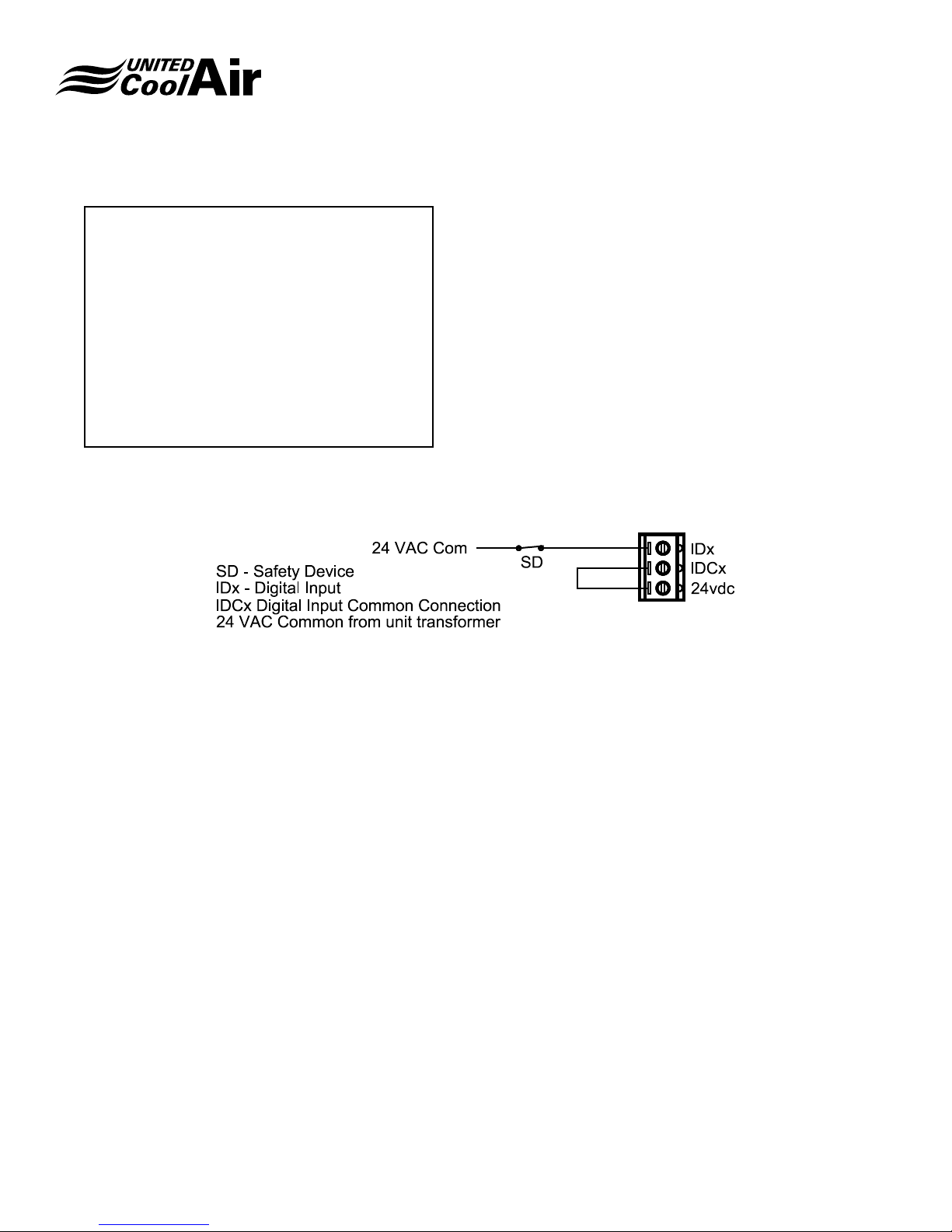
Installation, Operation and Maintenance Manual
Marvel Mini
U01 Information
System Info
Board Type> c.pCO
Board Size> Large
Board Temp> 104 °F
PermMem Writes>0005400
Main Status:
150ms 5.6cycles/sec
The last screen within the Information sub-menu provides
details about the installed controller.
FIGURE 16 – DIGITAL INPUT TERMINATION REFERENCES
INPUT WIRING
Digital Inputs
The Digital Inputs on the Marvel can accept and perform
any of the control functions listed for Digital Inputs on page
4. The digital inputs are designed to work with 24 VAC or
24 VDC. When using the digital inputs with a dc voltage
source, a 24 V AC/DC common must be wired to the actual
digital input, and must also be the same as the connection
to the G0 terminal which is normally referenced to ground.
The +24 VDC would then be wired directly to the IDCx or
common for the digital input. Refer to Figure 16 – Digital
Input Termination References for further details.
Analog Inputs
The Universal Inputs on the Marvel controller are provided
for reading any of the listed Universal/Analog Input sensors
listed on page 4.
The NTC temperature sensors are connected as shown in
Figure 17 – Temperature Sensor Termination References.
There is no polarity to the NTC temperature sensors.
FIGURE 17 – TEMPERATURE SENSOR TERMINATION
REFERENCES
Subject to change without notice. 120.9-IM (1218)
59
Page 60
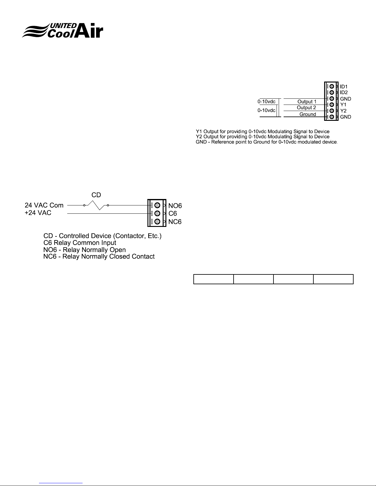
For all other sensor terminations, please refer to the
electrical diagrams provided with the units for electrical
connections.
Digital Outputs
Relays on a Marvel controller are capable of handling up to
10 Amps Resistive at 1 Amp Inductive loading at 250 VAC to
control any of the Digital Output functions listed on page 5.
To power a control device (contactor, starter, solenoid coil,
etc.) connect the neutral side of the 24 VAC power supply
to the control device. Connect the hot side of the 24 VAC
power supply through the common C(x) of the digital output
relay as shown in Figure 18 – Digital Output Termination
References.
Installation, Operation and Maintenance Manual
Marvel Mini
FIGURE 19 – ANALOG OUTPUT TERMINATION
REFERENCES
OPTIONAL BOARDS
FIGURE 18 – DIGITAL OUTPUT TERMINATION REFERENCES
Analog Outputs
The Analog Outputs on a Marvel controller are capable of
providing modulating output voltage of 0 – 10 VDC to control
any of the following Analog Outputs listed on page 4. The
analogs outputs must be powered externally using 24 VAC.
The neutral side of the 24 VAC power supply is connected to
terminal VG0. The 24VAC hot side is connected to terminal
VG1. Analog Output 1 through Analog Output 6 (Y1 through
Y6 respectively) connects to the modulating output for the
device being controlled. Refer to Figure 19 – Analog Output
Termination References for connection details.
Building Management Systems (BMS
Systems)
Several methods of supervisory systems may be used to
communicate with the Marvel Main Board which allow for
monitoring of the systems readings, changing/offsetting of
set points and remotely view alarm status. The following is
a list of BMS Systems the Marvel Control can interface with:
BACnet
TM
ModBus® LonWorks® pCOWeb
Subject to change without notice. 120.9-IM (1218)
60
Page 61
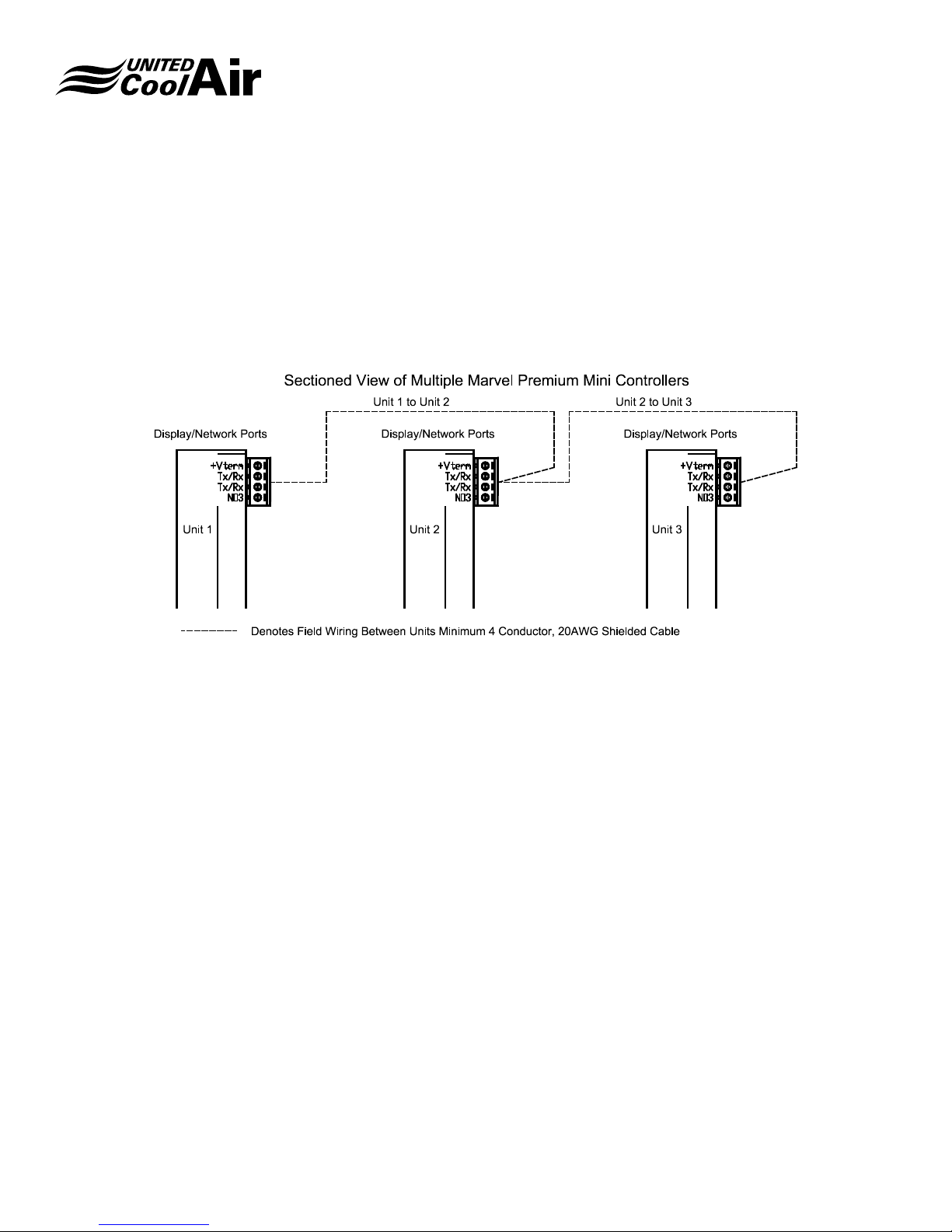
Installation, Operation and Maintenance Manual
Marvel Mini
SYSTEM NETWORKING
Two or multiple units may be networked as shown in Figure
1 previously. The networks are precongured during the
operational testing at the factory using Ethernet Cables.
1. Connect eld supplied Ethernet Cables between
the controllers as shown in Figure 20 – System
Networking below.
FIGURE 20 – SYSTEM NETWORKING
a. Network wiring between each unit must be installed
between each unit as follows:
i. Unit 1 connects to Unit 2
ii. Unit 2 to Unit 3
iii. Unit 3 to Unit 4 and so on.
b. Network wiring must be 4 Conductor Minimum 20
AWG shielded cable.
2. Should there be a need to re-order the number of unit
identication, Figure 21 – Adjusting pLAN Addresses
below displays the location and momentary push
button access for renumber the plan networking
addresses.
a. Simply insert a very small screw drive in through
the momentary pushbutton opening.
b. Depress the button one time and the LEDs shown
at 31 will illuminate to a higher intensity.
c. Once they are brighter, keep pressing the button
until the desired plan address is achieved.
d. Stop depressing the button to save the plan
address into memory.
FIGURE 21 – ADJUSTING PLAN ADDRESSES
Subject to change without notice. 120.9-IM (1218)
61
Page 62
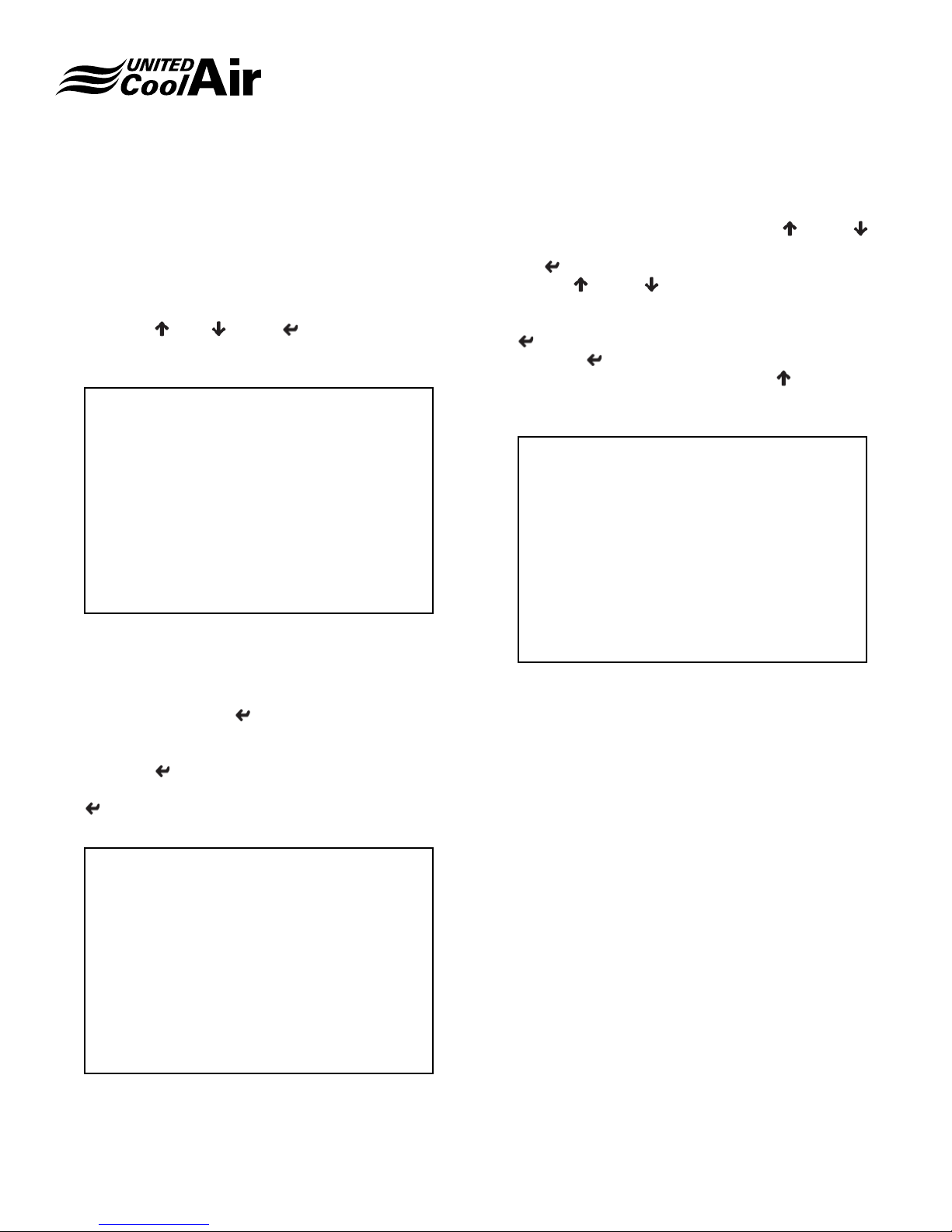
Installation, Operation and Maintenance Manual
Marvel Mini
3. If the units were ordered from the factory as a
networking system, the following procedure will have
already been completed and tested. Each unit must be
shared with the Marvel Terminal/Wall Display. In order
to do this, disconnect power to all but one unit. Each
unit will be updated one at a time.
4. Press the
simultaneously for 5 seconds until the following screen
appears.
(up), (down) (enter) and buttons
Display address
setting............ :32
I/O Board address: 01
5. Make sure the display address it set to a 32. On the
present unit being updated, the I/O Board address
should automatically appear. If it does not appear, a
-- will appear. Simply position the blinking cursor over
the -- by pressing the (enter) it is positioned at this
location. Press the up or down button until the pLAN
address shown in Figure 20 appears at this location.
Press the (enter) button until the next screen
appears and then once this screen appears, press the
(enter) button again till the Priv/Shared Screen as
shown appears.
6. Trm1 must be a value of 32 to match the value
previously set. If it is not a 32, use the
(down) buttons to change the value to a 32 then press
the (enter) button to save it into memory. Next,
use the
value under Priv to make sure that if Pr is displayed,
the value must be Sh for Shared and then press the
(enter) button to save it into memory. Continue to
press the (enter) button until the blinking cursor is
positioned under the NO and use the
to change the value to Yes. Once this is nished, the
main status screen will reappear.
(up) or (down) buttons to change the
(up) or
(up) button
P:01 Adr Priv/Shared
Trm1 32 Sh
Trm2 None --
Trm3 None -- ok?NO
7. At this point, power this unit down and repeat the
previous steps to share each unit with the Marvel
Terminal. It is easiest to do one unit at a time making
sure that power is applied only to the unit being
updated. Once all units have been updated, power can
be applied to all units.
Terminal config
Press ENTER
To Continue
Subject to change without notice. 120.9-IM (1218)
62
Page 63
NOTES:
Installation, Operation and Maintenance Manual
Marvel Mini
Subject to change without notice. 120.9-IM (1218)
63
Page 64
Unique Solutions for All-Indoor HVAC Projects
VertiCool Classic
Vertical, 3 - 30 Ton
Portable Cooling and
Heating Units
3-30 Tons
Authorized Distributor:
VertiCool Aurora
Vertical, 3 - 35 Tons
C13-Series Horizontal
2 - 10 Tons
VariCool®
VAV, 9 - 70 Tons
C-Series Horizontal
1 - 15 Tons
Special Configuration
Engineered to Order
VariCool® EZ-Fit
VAV, 12 - 90 Tons
OmegaAir Vertical
100% Outside Air, 1 - 15 Tons
OmegaAir Horizontal,
100% Outside Air, 1 - 15 Tons
LIMITED WARRANTY
United CoolAir Units are backed by a 1 year limited warranty on
parts and a 5 year limited warranty on the compressor (labor not
included). Maintenance items such as lters and belts are excluded
under this limited warranty.
FACTORY TESTED
All units are functionally run tested before shipment to ensure a
trouble-free start-up and unit commissioning. Industry proven
components are used throughout to enhance system reliability and
peace of mind.
Scan to learn more
about all of our
products!
491 East Princess Street, York, PA 17403 Phone: 717-843-4311 Fax: 717-854-4462
email: [email protected] web: www.unitedcoolair.com
Copyright © by United CoolAir Corporation 2018. All rights reserved.
Manufacturer reserves the right to make changes without notice.
120.9-IM (1218)
 Loading...