

Page 1
Marvel BMS
communications
Installation, Operation and Maintenance Manual
Effective April 2019
DISCONTINUED
For Reference Only
***Interactive PDF***
Page 2

Installation, Operation and Maintenance Manual
Contents
General Purpose �����������������������������������������������������������������������������������������������������������3
Components ������������������������������������������������������������������������������������������������������������������4
Architectural Layout �������������������������������������������������������������������������������������������������������5
General Serial Card Installation�������������������������������������������������������������������������������������6
Initial installation� �����������������������������������������������������������������������������������������������������6
Connection Setup from Marvel to Serial Card ���������������������������������������������������������6
Network Connection Settings and Access ���������������������������������������������������������������6
Accessing Bacnet network settings� ������������������������������������������������������������������������6
PCONET adjustable parameters for Bacnet protocol� Bacnet MS/TP setup� ����������7
PCOWEB adjustable parameters for Bacnet protocol� Bacnet IP setup� ����������������7
LonWorks setup ������������������������������������������������������������������������������������������������������7
Modbus setup ����������������������������������������������������������������������������������������������������������7
Points list’s referencing �������������������������������������������������������������������������������������������7
CSV Files ����������������������������������������������������������������������������������������������������������������8
Troubleshooting �������������������������������������������������������������������������������������������������������������9
Marvel BMS
Subject to change without notice. 120.5-IM (0419)
2
Page 3
Installation, Operation and Maintenance Manual
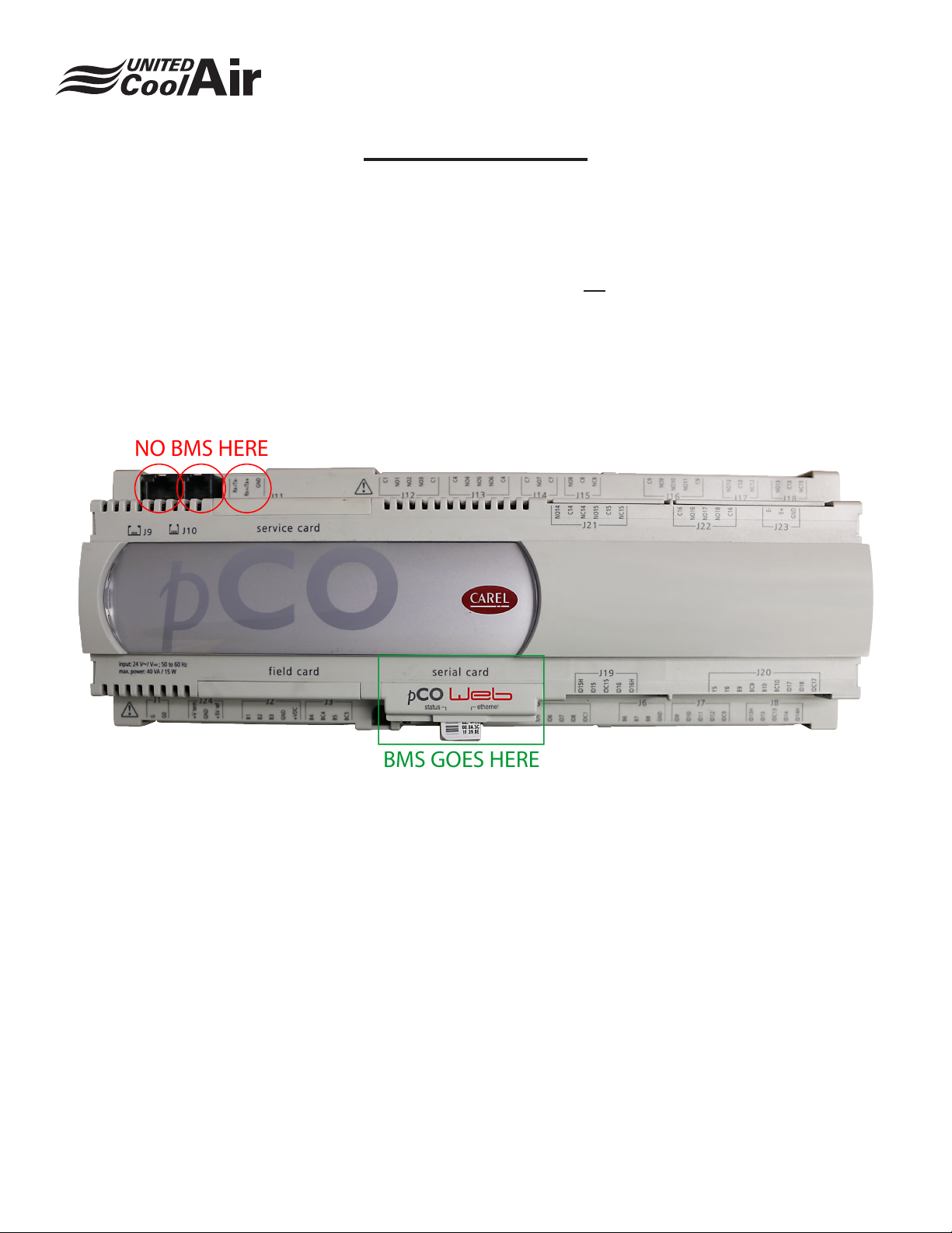
NO BMS HERE
BMS GOES HERE
General Purpose
Marvel BMS
The Marvel BMS communications availability is designed to
give a general control and monitoring ability to any of the
Marvel controllers� It is not designed to control the actual
individual components of the units� The Marvel controls
program is designed to maximize efciency of the unit and
will follow through with its own sequence of operations�
The BMS communications can be used on all of the existing
Marvel controllers and although some may have more ability
than others they all have ability’s that are most commonly
associated with a BMS management system such as system
on off, Alarm monitoring, status monitoring, conditions
monitoring, and set points access�
All Marvel equipment can communicate via Bacnet, Modbus,
and LonWorks� All controllers require a serial communications
card which is not a standard option for a Marvel controller
to communicate to a BM system� The only exception is the
Marvel controllers utilizing the pCO 5 controller� The pCO
5 controller can communicate via Modbus without a serial
card� All other types of BMS communication will require a
serial card for the pCO 5�
Subject to change without notice. 120.5-IM (0419)
3
Page 4
Installation, Operation and Maintenance Manual
Components
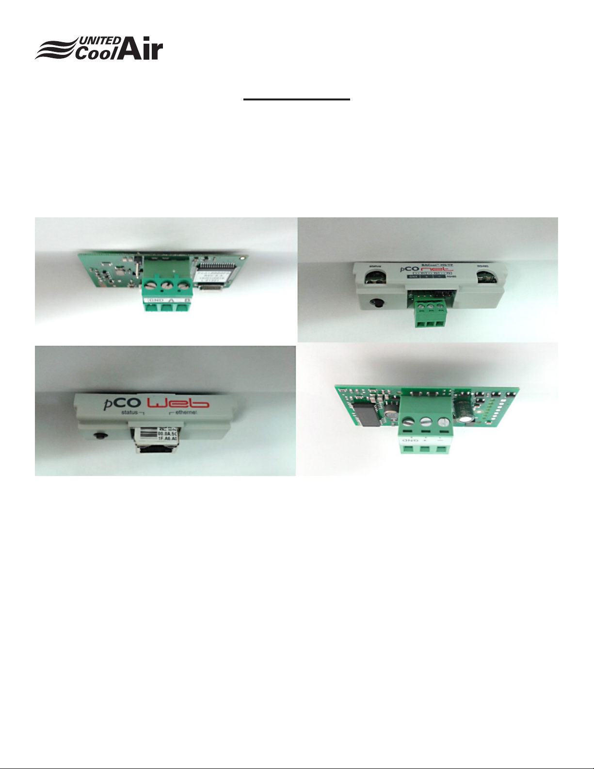
There are several different types of communication cards available to communicate via BMS�
LonWorks (FIG1)
Bacnet mstp (FIG2)
Bacnet/Modbus IP (FIG3)
Modbus mstp (FIG4)
Marvel BMS
Fig 1
Fig 3
Fig 2
Fig 4
Subject to change without notice. 120.5-IM (0419)
4
Page 5
Installation, Operation and Maintenance Manual
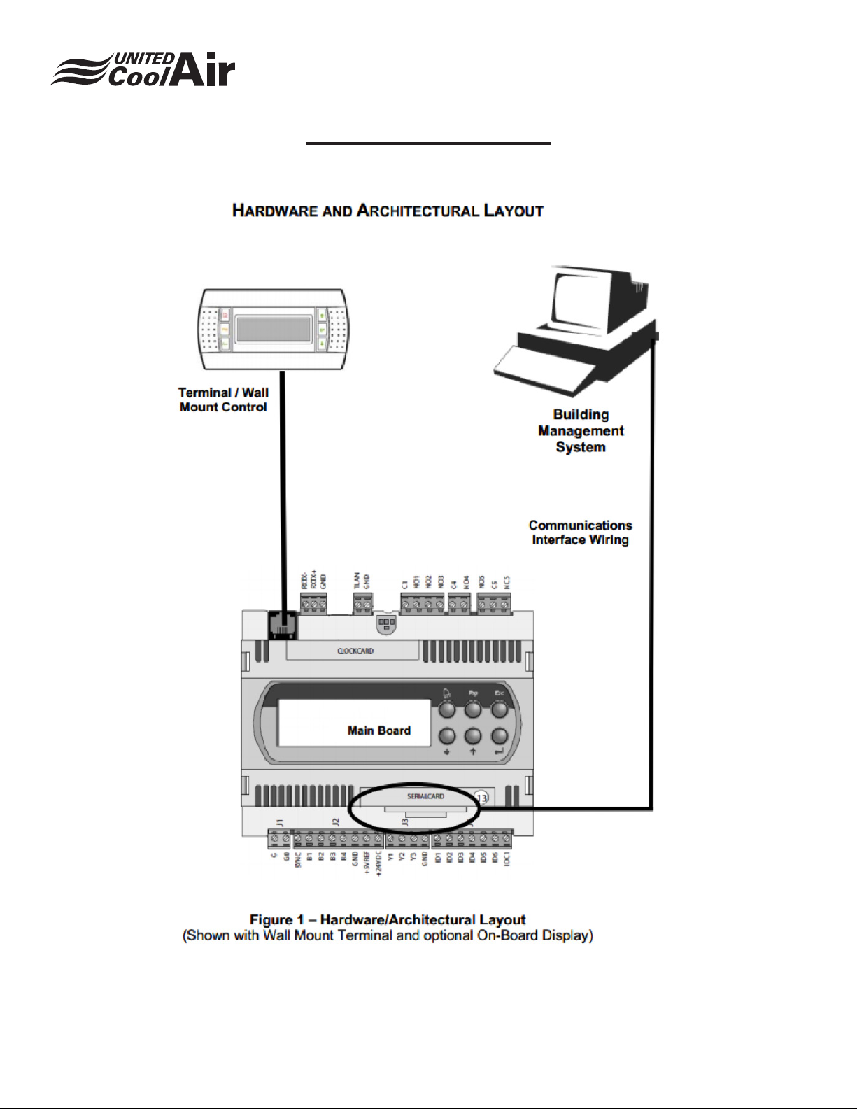
Architectural Layout
Marvel BMS
Subject to change without notice. 120.5-IM (0419)
5
Page 6
General Serial Card Installation
Initial installation.
It’s important to know what type of communications will
be required at the building and or what the Marvel will be
required to connect to� It’s important to understand the
architecture rst before installing a serial card or attempting
to connect via your BMS communications� Once you know
what card you are going to be installing you can remove the
cover from the serial card bay� Then you can insert the card
carefully into the bay and dock it to the connection� Place
the new serial card cover in place of the stock cover you
removed in the rst step.
The serial cards have their own wiring connections built
in and those will be the connections utilized for the proper
operation and communication of the Marvel controller over
BMS�
To verify the installation is complete reference the operation
lights on the serial cards when the controller is turned on to
verify it was loaded into the bay properly�
Connection Setup from Marvel to Serial Card
Once your serial card is in the Marvel Controller, you will need
to setup the communication between the Marvel Controller
and the Serial card that was installed� Boot the controller
and use the keypad provided to access the main menu list�
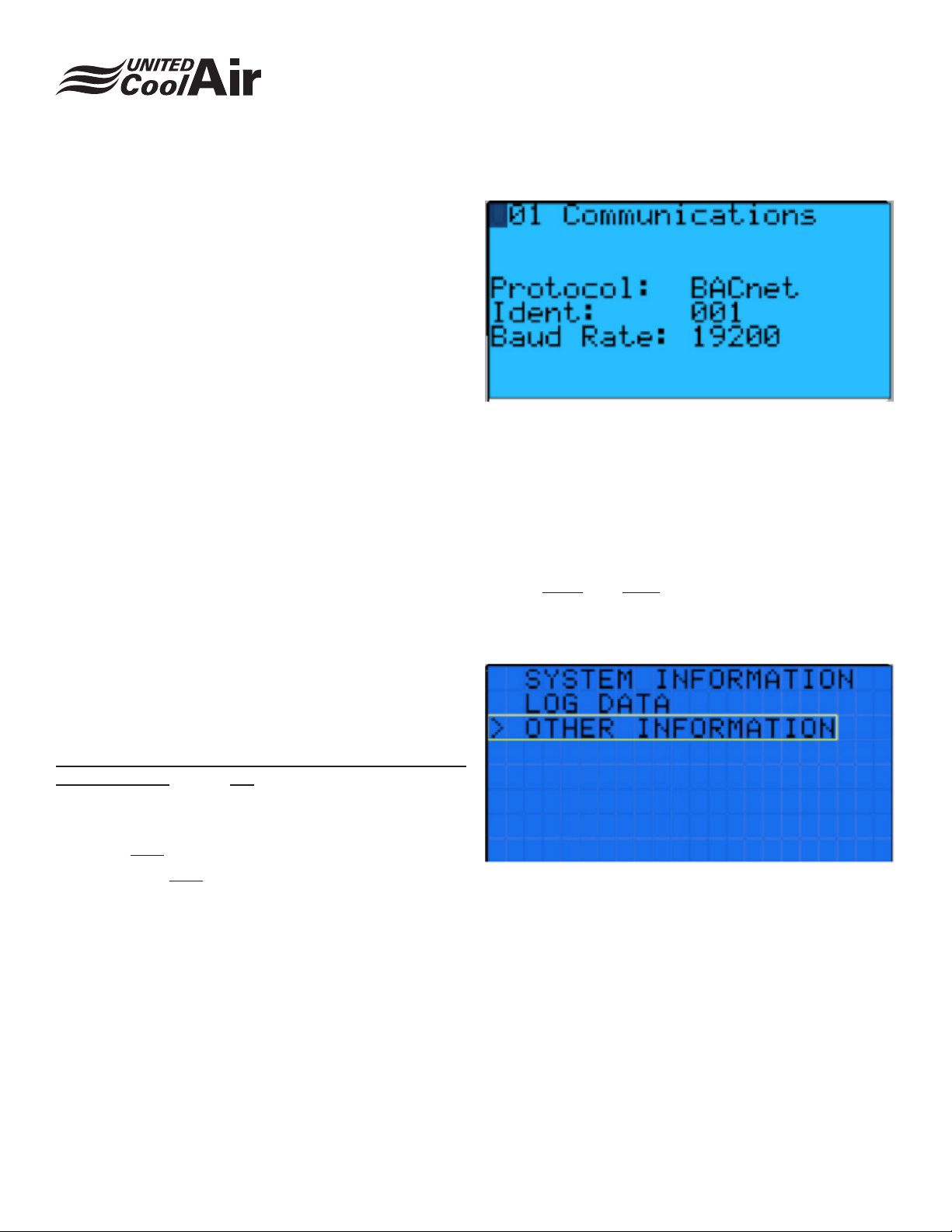
Scroll down to the BMS setup� Inside the BMS setup there
are only 3 options to setup� These settings pertain to the
communication between the Marvel Controller and the
Serial card only. This is not setting up any connection in
regards to the BMS server and its network.
The Protocol: set this to the desired BMS protocol�
The Ident: Must stay at 001 for all BMS protocols
The Baud Rate: Must stay at 19200 for Bacnet and Modbus
and must be at 4800 for LonWorks�
Installation, Operation and Maintenance Manual
Marvel BMS
Network Connection Settings and Access
To access settings that will be used by the network, follow the
appropriate protocol� The steps may be different depending
on the type of BMS protocol to be used�
Accessing Bacnet network settings.
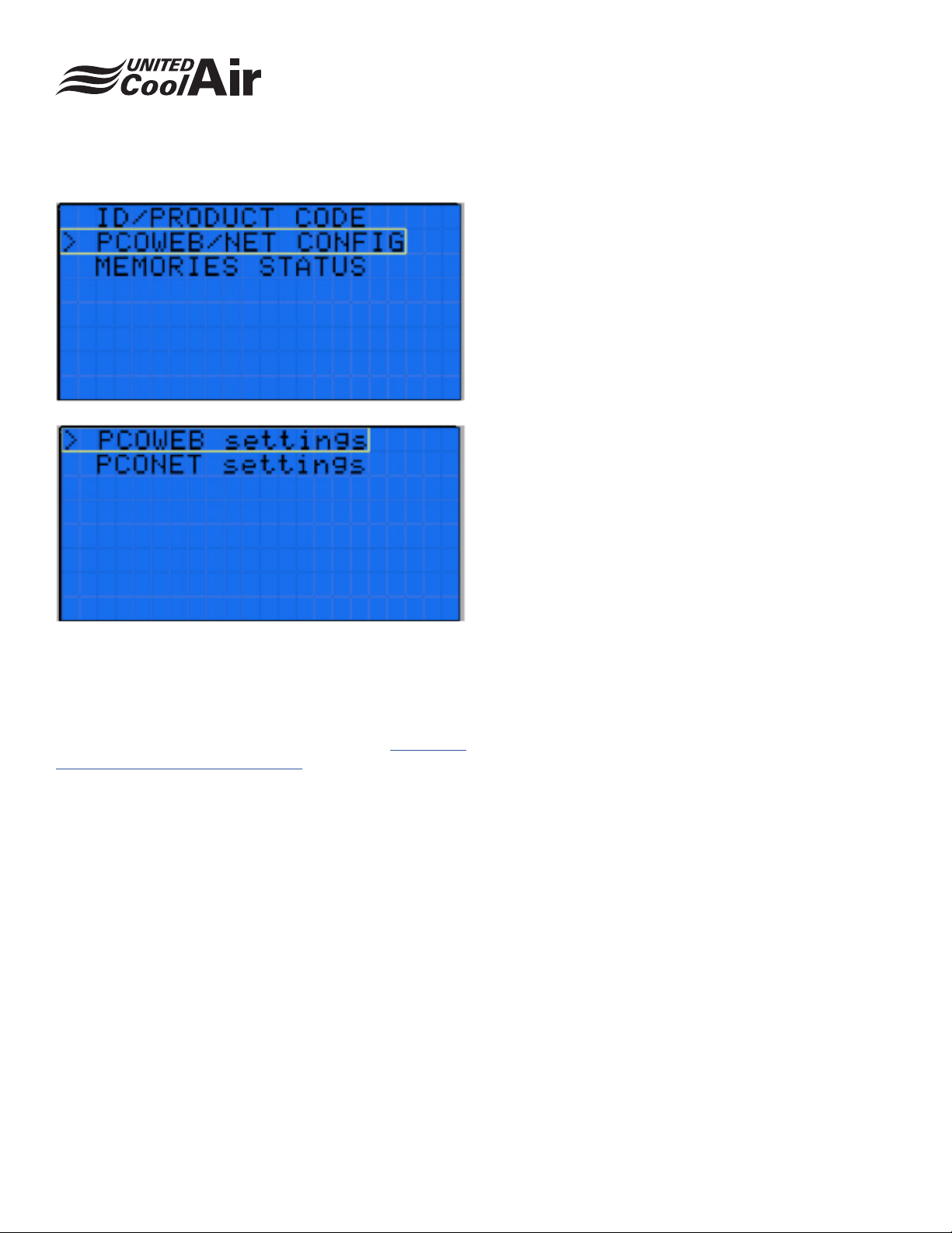
For new units with the PGD1 display you will [hold in the
buttons Alarm and Enter] until you see a screen change�
Once you see the screen change you have pressed the
buttons correctly and can release them� The next step is to
scroll to the “Other information”�
Subject to change without notice. 120.5-IM (0419)
6
Page 7
Installation, Operation and Maintenance Manual
Marvel BMS
the information in the rare case of saving trouble repeat the
steps above it will eventually save your settings�
PCONET adjustable parameters for Bacnet
protocol. Bacnet MS/TP setup.
You can setup various aspects of the Bacnet protocol for
your network in this page� You can adjust options such as the
Bacnet ID, the Bacnet Baud, The Bacnet MAC address, the
max masters and the max frames� The last menu option is
the update current info option� You simply have to select NO
to restart at the top or YES to save the information entered
on this page�
PCOWEB adjustable parameters for Bacnet
protocol. Bacnet IP setup.
For Bacnet WEB applications you can set up options like
your DHCP MODE, IP address, and Net mask, Gateway,
DNS1, DNS2, Bacnet ID and Bacnet Type of IP or Ethernet�
The last menu option is the update current info option� You
simply have to select NO to restart at the top or YES to save
the information entered on this page�
Select the PCOWEB/PCONET settings next� The next menu
will allow you to choose the most appropriate selection based
on the type of BMS you are using� WEB for IP or Ethernet
and NET for rs-485 applications� The pCO web application
is more complicated to initially start up� The CAREL manual
specically for the pCO web can be found here. http://www�
carelusa�com/product/pcoweb-card/�
Sometimes it is difcult to get the changes to save. If this
happens revert the settings back to factory and then try to
save� Factory settings usually save then go back to your
settings� It saves with a higher percentage when the wiring
is OFF of the controller’s BMS card� Continue to try to save
LonWorks setup
LonWorks requires factory setup of the LonWorks cards�
The cards rstly must all have the same SPID number to
communicate on the same network� This is crucial� UCA
facility’s handle the setup and conguration of the LonWorks
card itself. Some eld adjustment will likely be required.
Modbus setup
Modbus only requires the setup as shown in Connection
Setup from Marvel to Serial Card, once the protocol is set
to Modbus, it will be ready to communicate�
Subject to change without notice. 120.5-IM (0419)
7
Page 8
Points list’s referencing
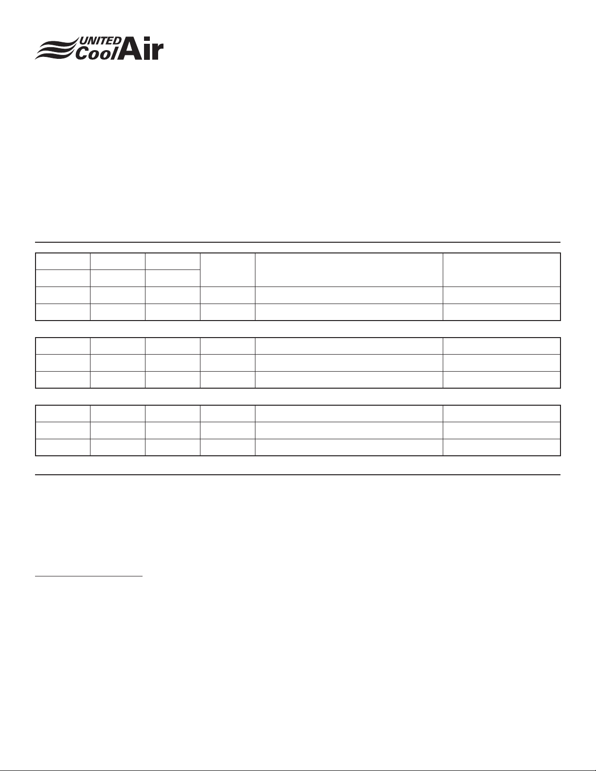
UCA will provide points list’s for the different programs on
the website� www�unitedcoolair�com/ the points lists are laid
out in a table� The table can be navigated as such in the
example below� Notice the following from left to right� On
the top of the page there is the header information� It has
listed the different protocols and what their programmed
access point number is for the variable� R/W stands for read
write capability� If there is an R/W you can write and read the
Installation, Operation and Maintenance Manual
Marvel BMS
values� If there is only an R you can only read the values�
The description lists a description of what the variable is
based on its operation or control. The rst row there it is
understood that the variable will turn the system on and off�
The Value range column simply shows the available values
and if necessary what those values represent� LonWorks
has their own specic tables but are laid out the same way.
Bacnet Modbus Carel
Binary Digital Digital
1 10002 1 R/W Keypad - System On/Off 0=Off, 1=On
2 10003 2 R Operating Mode - Cooling 1=Cooling
Analog Analog Analog
1 40002 1 R Room/Return Air Temperature -450 - 1850
2 40003 2 R Outdoor Air Temperature -450 - 1850
Integer Integer Integer
1 40130 1 R Supply Blower Run Hours
2 40131 2 R Compressor 1 Run Hours
R/W United CoolAir Description Value Range
CSV Files
At the current time ALL programs have the BMS descriptions
built into the Bacnet communications� These descriptions
can be pulled from the card under “Discovery Mode”� This
means that a points list will not be necessary for marvel
point’s description assignment�
TIPs on points to control�
There must be a great deal of thought when choosing how to
control the unit� UCA units can be independently controlled
entirely on their own. They are setup to be as efcient as
possible, the efciency setup is kept intact when the system
maintains its sequence of operations that are carefully
programmed by the factory� There is a vast amount of manual
control points that can be controlled by a BMS system� Their
main function is for testing of equipment not for operating
them on a daily bases� It is a must to read and understand
the computer controller IOM for your unit prior to attempting
to control/monitor anything other than your system on off
and occupied unoccupied control�
Subject to change without notice. 120.5-IM (0419)
8
Page 9
Installation, Operation and Maintenance Manual
Marvel BMS
Troubleshooting
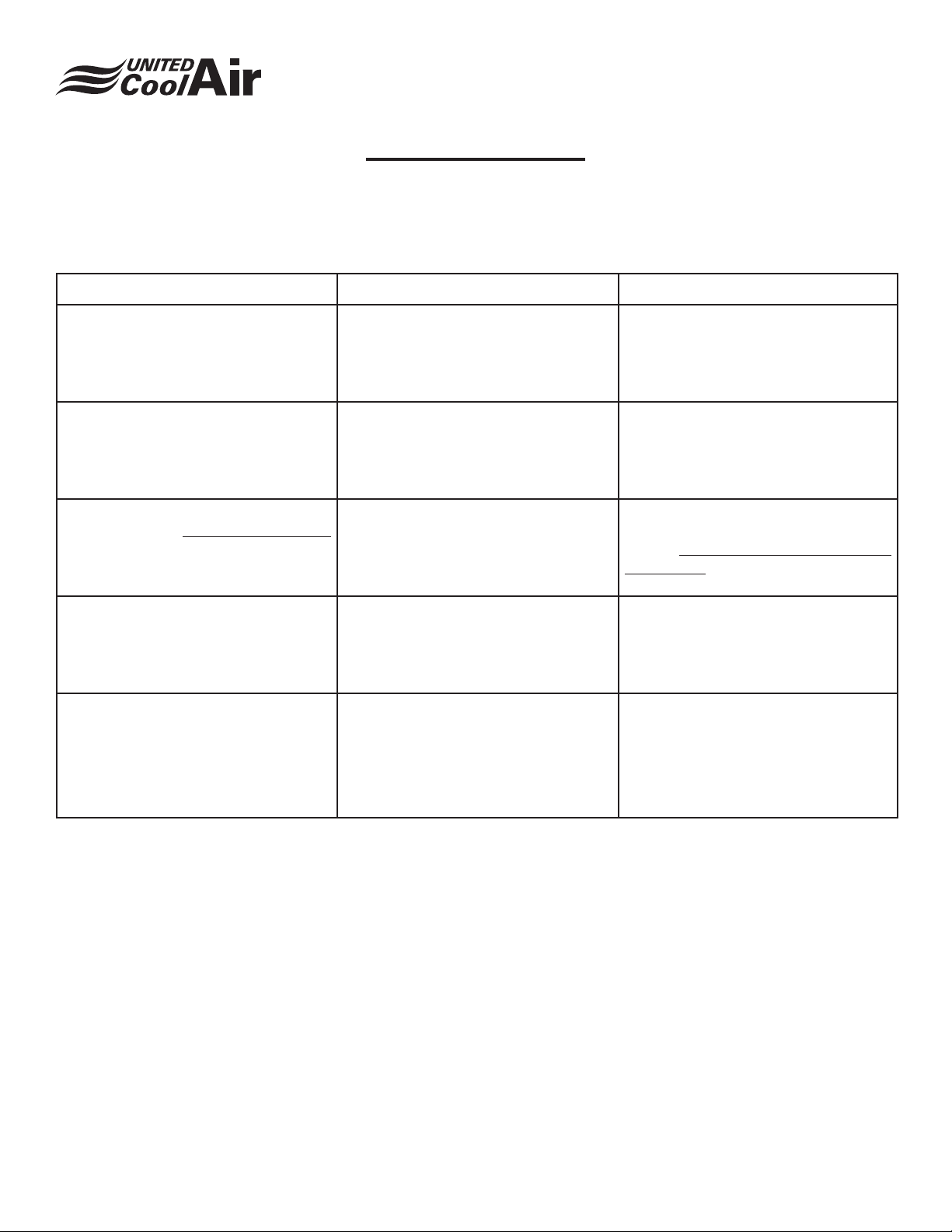
It is very important to eliminate possibility of eld errors before adjusting the controller. No eld
wiring, network, or BMS server programming are addressed here.
Issue Possible cause Remedy
Failure to communicate to the board
entirely Attempt1
Failure to communicate to the board
entirely Attempt2
Failure to communicate to board
entirely Attempt3 Bacnet protocols only
BMS communication is connected but
no values or points can be pulled
BMS cannot read certain units in the
network
BMS connection placed on the control
board’s communication ports and not
the serial card communication ports
BMS setup is not properly set for the
protocol in the controller
Pco net/web may not be properly setup
in the eld conguration area.
BMS setup is not properly set for the
protocol in the controller because the
serial card can’t read the boards output
The individual addresses may be setup
improperly or not at all�
For Bacnet mstp, the termination
jumpers on the serial card are not
installed properly for the installation of
the eld setup.
Verify the bms cable is landed ONLY on
the serial card ports and not the Rxtx
on the CAREL board or the Ethernet
port on the control board�
Enter the BMS setup in the programs
main menu and verify the protocol and
baud rate is setup as prescribed�
Verify the Pcoweb/Pconet settings
were congured properly as specied
in the Network Connection Settings
And Access section
Enter the BMS setup in the programs
main menu and verify the protocol and
baud rate is setup as prescribed�
Verify the Pcoweb/Pconet settings
were congured properly as specied
in the Network Connection Settings
And Access section
Adjust jumpers on Bacnet mstp cards
correctly per eld requirements
Subject to change without notice. 120.5-IM (0419)
9
Page 10
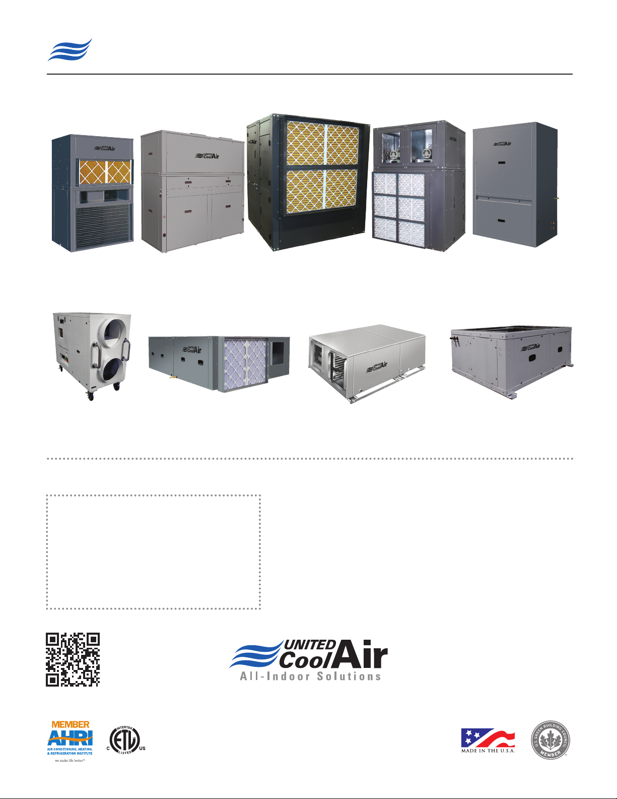
Unique Solutions for All-Indoor HVAC Projects
VertiCool Classic
Vertical, 3 - 30 Ton
Portable Cooling and
Heating Units
3-30 Tons
Authorized Distributor:
VertiCool Aurora
Vertical, 3 - 35 Tons
C13-Series Horizontal
2 - 10 Tons
VariCool®
VAV, 9 - 70 Tons
C-Series Horizontal
1 - 15 Tons
Special Configuration
Engineered to Order
VariCool® EZ-Fit
VAV, 12 - 90 Tons
OmegaAir Vertical
100% Outside Air, 1 - 15 Tons
OmegaAir Horizontal,
100% Outside Air, 1 - 15 Tons
LIMITED WARRANTY
United CoolAir Units are backed by a 1 year limited warranty on
parts and a 5 year limited warranty on the compressor (labor not
included). Maintenance items such as lters and belts are excluded
under this limited warranty�
FACTORY TESTED
All units are functionally run tested before shipment to ensure a
trouble-free start-up and unit commissioning� Industry proven
components are used throughout to enhance system reliability and
peace of mind�
Scan to learn more
about all of our
products!
491 East Princess Street, York, PA 17403 Phone: 717-843-4311 Fax: 717-854-4462
email: [email protected] web: www.unitedcoolair.com
Copyright © by United CoolAir Corporation 2015. All rights reserved. Manufacturer
reserves the right to make changes without notice.
120.5-IM (0419)
 Loading...