

United cool air C13-Series Installation, Operation And Maintenance Manual
C13-Series
Installation, Operation and Maintenance Manual
Effective August 2018
Air-Cooled, Water-Cooled, Chilled Water and Heat Pump
Horizontal

Contents
Installation, Operation and Maintenance Manual
C13-Series
Contents � � � � � � � � � � � � � � � � � � � � � � � � � � � � � � � � � � � � � � 3
Wiring Diagram � � � � � � � � � � � � � � � � � � � � � � � � � � � � � � � � 4
Important Notice� � � � � � � � � � � � � � � � � � � � � � � � � � � � � � � � 5
Use of Symbols� � � � � � � � � � � � � � � � � � � � � � � � � � � � � � � � � 5
C13-Series Air-Cooled Package � � � � � � � � � � � � � � � � � � � 6
C13-Series Water-Cooled Package� � � � � � � � � � � � � � � � � 7
General Information � � � � � � � � � � � � � � � � � � � � � � � � � � � � � 8
Inspection Of Equipment � � � � � � � � � � � � � � � � � � � � � � � � 8
Handling � � � � � � � � � � � � � � � � � � � � � � � � � � � � � � � � � � � � � 8
Location � � � � � � � � � � � � � � � � � � � � � � � � � � � � � � � � � � � � � 8
Mounting And Setting In Place� � � � � � � � � � � � � � � � � � � � 8
Installation� � � � � � � � � � � � � � � � � � � � � � � � � � � � � � � � � � � � � 9
Split Systems � � � � � � � � � � � � � � � � � � � � � � � � � � � � � � � � � � 9
Separation Of Sections � � � � � � � � � � � � � � � � � � � � � � � � � � 9
Interconnecting Refrigerant Tubing � � � � � � � � � � � � � � � 10
Single Package Unit Wiring� � � � � � � � � � � � � � � � � � � � � � 13
Split System Wiring � � � � � � � � � � � � � � � � � � � � � � � � � � � � 13
Duct Connection� � � � � � � � � � � � � � � � � � � � � � � � � � � � � � � 13
Pressure Switches � � � � � � � � � � � � � � � � � � � � � � � � � � � � � 13
High Pressure � � � � � � � � � � � � � � � � � � � � � � � � � � � � � � � 13
Low Pressure � � � � � � � � � � � � � � � � � � � � � � � � � � � � � � � � 13
Water-Cooled Condensing Units � � � � � � � � � � � � � � � � � 13
Water-Cooled Condenser� � � � � � � � � � � � � � � � � � � � � � � 13
Water Piping and Connections� � � � � � � � � � � � � � � � � � � 13
Hook Up � � � � � � � � � � � � � � � � � � � � � � � � � � � � � � � � � � � � 14
Water Connection� � � � � � � � � � � � � � � � � � � � � � � � � � � � � 14
Condensate Drain Connection � � � � � � � � � � � � � � � � � � � 14
Maintenance Procedures� � � � � � � � � � � � � � � � � � � � � � � � 15
Filters� � � � � � � � � � � � � � � � � � � � � � � � � � � � � � � � � � � � � � � � 15
Cleaning The Water-Cooled Condenser� � � � � � � � � � � � 15
Blowers � � � � � � � � � � � � � � � � � � � � � � � � � � � � � � � � � � � � � � 16
Blower Motors� � � � � � � � � � � � � � � � � � � � � � � � � � � � � � � � � 17
Blower Speed Adjustment � � � � � � � � � � � � � � � � � � � � � � � 17
Blower Motor Lubrication � � � � � � � � � � � � � � � � � � � � � � � 17
Belts� � � � � � � � � � � � � � � � � � � � � � � � � � � � � � � � � � � � � � � � � 18
Refrigerant Systems� � � � � � � � � � � � � � � � � � � � � � � � � � � � 18
Evaporator And Air-Cooled Condenser Coils � � � � � � � 18
Minimum Service Access � � � � � � � � � � � � � � � � � � � � � � � 18
Application Data � � � � � � � � � � � � � � � � � � � � � � � � � � � � � � � 18
Hard Start Kit � � � � � � � � � � � � � � � � � � � � � � � � � � � � � � � � � 18
Sequence Of Operation � � � � � � � � � � � � � � � � � � � � � � � � � 19
Cooling Sequence Of Operation � � � � � � � � � � � � � � � � � � 19
Heating Sequence Of Operation (Other Than Heat
Pump) � � � � � � � � � � � � � � � � � � � � � � � � � � � � � � � � � � � � � � � 19
Heat Pump Heating Sequence Of Operation � � � � � � � � 20
Options � � � � � � � � � � � � � � � � � � � � � � � � � � � � � � � � � � � � � � 20
Condensate Pump � � � � � � � � � � � � � � � � � � � � � � � � � � � � � 20
Thermostat � � � � � � � � � � � � � � � � � � � � � � � � � � � � � � � � � � � 21
Checking Hot Gas Bypass Valve� � � � � � � � � � � � � � � � � � 21
Adjustment Of Hot Gas Bypass Valve � � � � � � � � � � � � � 22
Microprocessor Controller � � � � � � � � � � � � � � � � � � � � � � 22
Humidier � � � � � � � � � � � � � � � � � � � � � � � � � � � � � � � � � � � � 22
Electric Heat � � � � � � � � � � � � � � � � � � � � � � � � � � � � � � � � � � 22
Electric Reheat � � � � � � � � � � � � � � � � � � � � � � � � � � � � � � � � 22
Steam Coil� � � � � � � � � � � � � � � � � � � � � � � � � � � � � � � � � � � � 22
Hot Water Coils� � � � � � � � � � � � � � � � � � � � � � � � � � � � � � � � 23
Flooded Condenser � � � � � � � � � � � � � � � � � � � � � � � � � � � � 23
Buck/Boost Transformer � � � � � � � � � � � � � � � � � � � � � � � � 23
Chilled Water Valves Or Hot Water Valves � � � � � � � � � � 24
Head Pressure Control Valves � � � � � � � � � � � � � � � � � � � 24
Economizer Operation (Airside) � � � � � � � � � � � � � � � � � � 24
Economizer Operation � � � � � � � � � � � � � � � � � � � � � � � � � 24
Economizer Operation – (Waterside) � � � � � � � � � � � � � � 24
Condensing Section Outdoor Modication Kit � � � � � � 24
Split Condenser / Condensing Sections � � � � � � � � � � � 24
C13-Series Air-Cooled Condenser/ Condensing Section
With Outdoor Modication Kit� � � � � � � � � � � � � � � � � � � � 25
Vertical Stacking Unit� � � � � � � � � � � � � � � � � � � � � � � � � � � 26
Troubleshooting � � � � � � � � � � � � � � � � � � � � � � � � � � � � � � � 28
Limited Warranty � � � � � � � � � � � � � � � � � � � � � � � � � � � � � � 32
Limited Warranty for Hermetic Compressors � � � � � � � 33
Limited Warranty Condensing Section � � � � � � � � � � � � 34
Limited Warranty for Hermetic Compressors � � � � � � � 35
Air-Cooled Unit � � � � � � � � � � � � � � � � � � � � � � � � � � � � � � � 36
Start-Up Procedures (R-410a Systems)� � � � � � � � � � 36–37
Air-Cooled Unit � � � � � � � � � � � � � � � � � � � � � � � � � � � � � � � 38
Start-Up Procedures � � � � � � � � � � � � � � � � � � � � � � � � � � 38
Cooling Mode � � � � � � � � � � � � � � � � � � � � � � � � � � � � � � � � 39
Electrical� � � � � � � � � � � � � � � � � � � � � � � � � � � � � � � � � � � � 39
Heating Mode (Optional) � � � � � � � � � � � � � � � � � � � � � � � 39
Water-Cooled Unit � � � � � � � � � � � � � � � � � � � � � � � � � � � � � 40
Start-Up Procedures (R-410a Systems)� � � � � � � � � � � � � 40
Start-Up Procedures (R-410a Systems) Continued:� � 41
Optional Heating Start Up: � � � � � � � � � � � � � � � � � � � � � � 41
Water-Cooled Unit � � � � � � � � � � � � � � � � � � � � � � � � � � � � � 42
Start-Up Procedures � � � � � � � � � � � � � � � � � � � � � � � � � � 42
Cooling Mode � � � � � � � � � � � � � � � � � � � � � � � � � � � � � � � � 43
Electrical� � � � � � � � � � � � � � � � � � � � � � � � � � � � � � � � � � � � 43
Heating Mode (Optional) � � � � � � � � � � � � � � � � � � � � � � � 43
Basic Model Designation� � � � � � � � � � � � � � � � � � � � � � � � 44
Subject to change without notice. 10.20-IM (0818)
3
Installation, Operation and Maintenance Manual
C13-Series
Wiring Diagram
United CoolAir provides a wiring schematic for each unit produced� To retrieve the diagram for your unit please visit
www�unitedcoolair�com, on your computer or mobile device, scroll to the footer section or Home/industry-resources,
enter your serial number in the Serial Search eld and press return to retrieve your product-wiring diagram.
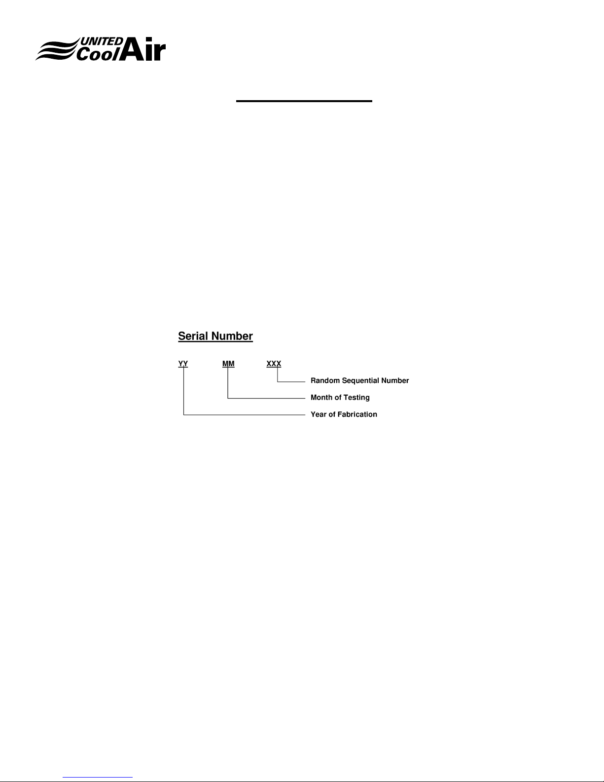
Your serial number is a combination of the year, month and sequential order of build date�
This action will return the Model number, Job Number and the wiring diagram for viewing as well as downloading�
NOTE: Only units shipped since November 2016 are available on the site, for older units please contact the factory directly
at 717-843-4311�
Subject to change without notice. 10.20-IM (0818)
4
Installation, Operation and Maintenance Manual
C13-Series
Important Notice
This manual is the property of the owner�
Please be sure to leave it with the owner when you leave the job�
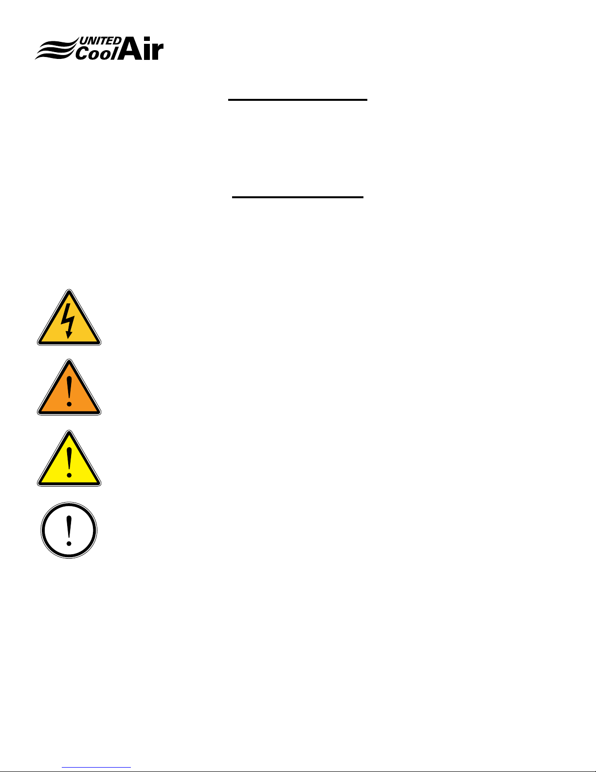
Use of Symbols
This publication includes warnings, cautions and information icons that point out safety related issues or conditions as well
as other pertinent information relative to a safe installation, service or maintenance situation� The following icons should be
interpreted as follows:
ELECTRICAL
HAZARD
WARNING
CAUTION
INFORMATION
The electrical hazard icon indicates the presence of an electrical hazard which
could result in electrical shock or death�
The warning icon indicates a potentially hazardous situation which could result
in death or serious bodily injury if not avoided�
The caution icon indicates a potentially hazardous situation which may result in
minor or moderate injury if not avoided�
The information icon indicates a situation that may result in equipment or
property damage� The information provided alerts the reader to relevant facts
and/or conditions�
Subject to change without notice. 10.20-IM (0818)
5
Installation, Operation and Maintenance Manual
C13-Series Air-Cooled Package
W
S
T R
½
C13-Series
Clearance Hole for
⅜" Hanging Rod
TYP 8 PLS
P
G
H
V
Evap
Return
Evaporator
Section
B
L M N 1 1
Evap
Supply
Air
FRONT RIGHT
Z X Y
Air
J
TOP
F
K
Condensing
Section
1
Service Clearance
All Sizes
Left Side 36"
Right Side 36
Field Installation
Power & Control
Wiring
Elect Box
Motor & Blower
Access Panel
D E 5
Elect Box
Motor & Blower
Access Panel
A
Cond
AA
AB AC
Tons A B C D E F G H J K L M N P Q R S T V W X Y Z AA AB AC AD
2–3 78 56 22 44 34 119⁄16 20 1 59 7 25 1011⁄16 91⁄16 3¼ 57 40½ 1¾ 30½ 91⁄16 3½ 24 35⁄16 13¼ 119⁄16 7 111⁄16 19
4–5 86 64 25 46 40 13 9⁄16 25 0 67 81⁄16 31½ 123⁄8 91⁄16 3 65 42½ 1¾ 36½ 91⁄16 3½ 32 35⁄16 123⁄8 139⁄16 81⁄16 111⁄16 22
6–8 108½ 70½ 32 63 45½ 18¾ 31½ ¼ 73½ 65⁄8 39½ 161⁄16 613⁄16 15⁄8 71½ 59½ 1¾ 42 91⁄16 3½ 24 11⁄16 1811⁄16 16 97⁄16 111⁄16 29
Air
Out
REAR LEFT
Cond
Air
In
Figure 1: Dimension Drawing
Subject to change without notice. 10.20-IM (0818)
AD
1⅛
C
Coil
Access
Panel
Refrigerant
Quick-Connect
Access Panel
Coil
Access
Panel
Condensate
Drain
Filter
Access
6
Installation, Operation and Maintenance Manual
C13-Series Water-Cooled Package
W
S
T
AG
½
C13-Series
Clearance Hole for
⅜" Hanging Rod
TYP 8 PLS
P
G
H
Evap
Air
Cond
Section
TOP
Service Clearance
All Sizes
Left Side 36"
Right Side 36
Field Installation
Power & Control
1 AK
F
K
Wiring
Elect Box
Motor & Blower
Access Panel
Evaporator
Section
B
L M N
Evap
Return
Air
FRONT RIGHT
Supply
J
Out
AJ
In
AH
AE
EAF 5
Elect
Box
Tons B C E F G H J K L M N P Q R S T W AE AF AG AH AJ AK
2–3 56 22 34 119⁄16 20 1 59 7 25 1011⁄16 91⁄16 3¼ 57 40½ 1¾ 30½ 3½ 50 16 12½ 6¼ 91⁄8 13 Ø⅞
4–5 64 25 40 13 9⁄16 25 0 67 81⁄16 31½ 123⁄8 91⁄16 3 65 42½ 1¾ 36½ 3½ 56 16 12½ 6½ 115⁄8 13 Ø11⁄8
6–8 70½ 32 45½ 18¾ 31½ ¼ 73½ 65⁄8 39½ 161⁄16 613⁄16 15⁄8 71½ 59½ 1¾ 42 3½ 56½ 20 16½ 71⁄8 10½ 17 Ø13⁄8
Access Panel
REAR LEFT
Figure 2: Water Cooled Dimension Drawing
Subject to change without notice. 10.20-IM (0818)
Compressor
1⅛
Refrigerant
Quick-Connect
Access Panel
7
Coil
C
Access
Panel
Condensate
Drain
Filter
Access
Water Piping
In & Out
Installation, Operation and Maintenance Manual
General Information
C13-Series
Inspection Of Equipment
Upon receipt of the unit, inspect for visible or concealed
damage. Report any damage to the carrier, and le a
damage claim�
Handling
To facilitate handling, the unit is set on a wooden skid so that
it may be picked up with a two-wheel hand truck or fork lift�
Under no circumstances should the unit be “walked” on the
corners of the skid� Use dolly trucks or pipe rollers to move
the unit to its proper location�
Location
Unit can be installed either as a complete package or split
into two sections. It can be either oor mounted or ceiling
mounted�
Before unit is installed, a thorough study should be made of
the structure� Careful consideration must be given to location
of wiring, condensate disposal, ductwork and accessibility
to the unit for maintenance and servicing� It is necessary
that a minimum clearance space be allowed on each side
of the unit to accommodate maintenance and servicing�
This minimum clearance must be 36" for all units. Attention
must also be given to oor, ceiling or wall load limitations
(See Figure 2)� Location should also provide for condensate
removal, trapping and disposal�
Discharge Air from condenser coil should be deected
away from supply air to condenser, to prevent
recirculation� See also “Condensing Section Outdoor
Modication Kit” on page 27.
CAUTION
Unit should not be located in space subject
to freezing temperatures�
Mounting And Setting In Place
Units can be shipped as an integral package with a tie rail
attached to both sides of the unit at each of the four mounting
channels�
If unit is not to be split but is to be hung, do not remove
tie rail. Use eld supplied (3/8" minimum diameter) hanging
rods, with proper washers and locknuts, then elevate unit to
the exact location where it is to be installed� Fasten the rods
securely to the supporting structure. Install eld supplied
vibration isolation as required� Level unit�
If unit is to be oor mounted and not separated, do not
remove tie rails� Locate on a level pad and secure as
necessary� Field supplied unit isolation can be installed as
required�
Subject to change without notice. 10.20-IM (0818)
8
Installation
Installation, Operation and Maintenance Manual
C13-Series
1� Air conditioner is shipped assembled and ready for
operation�
2� Unit contains a full charge of R-410a refrigerant�
3� Install unit so that controls and side panels are
accessible to the operator and maintenance personnel�
4� Run the condensate drain line by following the
guidelines on page 11�
5� Electrical Wiring
a� Once the unit is installed, refer to the wiring
diagrams which are provided on the backside of the
control box covers�
b� Units are completely internally wired at the factory
for commonly rated supply voltages� Check unit data
tags for required voltage, wire and fuse sizing� The
factory wiring terminates in two boxes; one each
in the evaporator and condensing sections� These
control boxes are located behind the outer access
panels� Each is supplied with an individual control
box cover with a wiring diagram attached inside�
c� All the units are provided with terminal blocks�
d� The power wiring to the unit is to be brought through
one of the available holes for the unit electrical
power connection(s)�
e� The control wiring is brought through the holes
provided in the unit�
f� Supply wiring must comply with all National or Local
codes� The power supply must be suitably fused for
wire protection�
g� Use copper conductors only� The unit must be earth
grounded using the ground lug provided in the
electrical box� Metal conduit is not an acceptable
ground�
h� Run the low voltage wiring from the thermostat to the
unit� Connect to low voltage terminal block supplied�
See “Thermostat” under “Options”, page 20�
Wire Size1 AWG� Gauge
Note:
1� Solid, Class II copper wire
2� Based on a voltage drop of 1�2 volts per wire�
3� Total wire length is from unit to room thermostat, and
back to unit�
FIGURE 3: Control Wire Sizes
Select a location to install the thermostat to avoid vibration,
drafts, sun exposure, or internal heat sources� Use an inside
wall�
Split Systems
If the unit was ordered for a split system application each
section will contain male resealable refrigerant ttings. Install
the mating female ttings and eld supplied tubing per the
instructions that follow� Note that Optional Interconnect Kits
are required for each circuit and external Hot Gas Bypass
circuit�
Separation Of Sections
If the unit is to be installed as a split system, the following
steps must be carefully followed in performing the separation�
1� Remove evaporator access panel�
2� Using an open-end wrench and turning counter-
clockwise, disconnect the female half of the selfsealing couplings on both the suction and discharge
lines� These are located in the bottom left area of the
evaporator section� When there is a hot gas bypass
option, that connection is to the right of the self-sealing
coupling connections� There is one suction line, one
liquid line, and one hot gas by-pass line (option) for
each compressor�
22 20 19 18 16
40 120 150 190 305
Maximum Wire Length2 Feet
Subject to change without notice. 10.20-IM (0818)
9

Installation, Operation and Maintenance Manual
C13-Series
INFORMATION
Two circuit units have 2 groups of couplings�
It’s a good idea to label or mark the various
connections on both the evaporator
and condensing sections BEFORE
DISCONNECTING THE COUPLINGS to
eliminate the possibility of intermixing the
circuits when the interconnecting tubing
is installed� The suction and discharge
lines in the evaporator section will now
be dangling, be careful not to damage the
tubing connections� Do not disconnect the
male half of the self-sealing couplings,
which are still attached to the bulkhead of
the condensing section�
3� Remove the unit top tie piece*, removing only those
screws which attach the top piece to the two top
panels� (*If unit is already shipped split, these are not
included�)
4� Remove control box access panels from the evaporator
section and the condensing section by removing the
screws at the top and bottom of each access panel�
5� Disconnect and discard the wires which run between
the two internal control boxes� Single circuit units will
have two low voltage wires to be disconnected, dual
units will have 3 low voltage wires� See Wiring Diagram
on the inside of the evaporator control box access
panels for disconnecting power wiring�
6� Remove the two unit tie rails attached to the unit
mounting rails on each side of the unit�
7� Carefully pull the evaporator section away from the
condensing section�
8� Verify that the self-sealing couplings are completely
disengaged and not leaking refrigerant�
The sections may now be moved to their individual locations
for installation (either oor-mounted or hung).
Interconnecting Refrigerant Tubing
After the separated sections have been installed, the eld
supplied interconnecting tubing can be run, using the selfsealing couplings supplied in the optional interconnecting
tubing kit� For dual circuit units, two kits are supplied� It is
recommended that some refrigerant oil be placed on the
coupling threads (Item (10), Figure 5), to facilitate threading�
The following instructions apply:
1� Hand thread the female halves of the self-sealing
couplings (supplied with the interconnect tubing kit)
onto the male couplings (fastened to the unit, Item
(5), Figures 4 and 5)� Turn union nut (Item (11), Figure
5), approximately 1 to 1-1/2 turns� This is to make
sure that the interconnecting tubing will be routed and
brazed with the self-sealing couplings in their nal
proper location, so that there will be no difculty when
the nal coupling assembly is made.
2� If there is a hot gas bypass option, connect that
coupling the same way�
3� Run the interconnecting tubing required�
5
4
Figure 4: Disconnect/Connect Self-Sealing Coupling Figure 5: Install/Service Self-Sealing Coupling
Subject to change without notice. 10.20-IM (0818)
10
Coupling Threads
10
13
5
12
13
Metal
15
Seal
14
Rubber
Seal
4
11
Union Nut
Installation, Operation and Maintenance Manual
C13-Series
Always follow accepted industry practices for sizing lines
based on line length and elevation differences�
Max� total equivalent line length = 100 ft� (a)
Max� elevation difference between Evap� and Cond� = 40 ft�
(a) (b)
Tons Suction Line Liquid Line
2 Ton 3/4 1/2
3 Ton 7/8 1/2
4 Ton 1-1/8 1/2
5 Ton 1-1/8 5/8
6 Ton (2) 7/8 (2) 1/2
8 Ton (2) 1-1/8 (2) 1/2
a� Contact the factory for installations with elevation
differences greater than 40 feet or total equivalent
line lengths greater than 100 feet� Alternate line
sizes and specic refrigerant components may be
required�
b� If condensing section is 20 feet or more above the
evaporator include an oil separator for each circuit�
Systems not ordered from the factory to be installed as a
split system will contain Female Fittings on the evaporator
section� Interconnect kit(s) must be ordered indicating that a
Male / Female Kit is required�
United CoolAir Corporation’s C13-Series horizontal units are
provided with unique self-sealing ttings on the refrigerant
lines between sections. These ttings or couplings allow the
two-section unit to be separated and reconnected without
loosing refrigerant charge�
When installed as a split system, an interconnect kit is
required for each refrigerant circuit or hot gas bypass line�
If the unit is dened as a split system when ordered, the
ttings will be male ttings on both sections. The interconnect
kit will then consist of the matching female ttings. An
interconnect kit is required for the eld to connect refrigerant
lines between both sections� Refrigerant piping between the
sections is eld supplied.
The interconnect kit also contains four (4) Schrader ttings.
The installer can place at least one in each refrigerant line or
at the end of the refrigerant line� These enable the refrigerant
line to be evacuated and charged as needed based on size
and length�
In some situations, the desired refrigerant line size may
differ from the self-sealing tting size provided. The line size
should be reduced or enlarged at the self-sealing ttings as
necessary
The drawing below illustrates a typical piping arrangement
A� Male self-sealing ttings on unit sections
B� Refrigerant piping between sections (eld-supplied)
C� Female self-sealing ttings in interconnect kit (4)
D� Schrader ttings in interconnect kit (4)
A
Evaporator
Section
A
D
C
D
C
D
B
D
B
C
C
A
Condensing
Section
A
FIGURE 6: Guidelines for Interconnecting Tubing Sizing
5� Disconnect and discard the wires which run between
the two internal control boxes (Item (9), Figure 5)�
Single circuit units will have two low voltage wires to
be disconnected, dual and triple units will have 3 low
voltage wires� See Wiring Diagram on the inside of the
evaporator control box access panels (Item (7), Figure
3) for disconnecting power wiring�
6� Remove the two side cross-member angles (Item (1),
Figures 3 and 5; and Item (2), Figure 4)�
7� Carefully pull the evaporator section away from the
condensing section� Double check that the self-sealing
couplings are completely disengaged�
The sections may now be moved to their individual locations,
either oor-mounted or hung.
INFORMATION
NOTE: Installations may be made with
up to 100 feet equivalent line lengths by
installing the recommended tube sizes
(See Figure 6) and adding the necessary
additional refrigerant, R-410a for the
eld installed line set. (See Step 7, page
10)� For equivalent line lengths greater
than 100 ft�, contact the factory for line
sizing and additional refrigerant circuit
accessories required�
Subject to change without notice. 10.20-IM (0818)
11

Installation, Operation and Maintenance Manual
C13-Series
INFORMATION
IMPORTANT! On units with more than one
refrigerant circuit, be careful not to intermix liquid, suction and/or hot gas lines
of the various circuits� If the connections
were labeled before disconnecting the
couplings, this should not be a problem�
The 6 Ton and 8 Ton units have 2 circuits
(with 2 suction line couplings and 2 liquid
line couplings)�
CAUTION
When brazing tubing to the self- sealing
couplings, use a water-soaked wet rag,
running water bath or chill blocks on the
quick-connects to prevent overheating the
valves and damaging the seals� Always
apply heat toward the eld installed
refrigerant line� Do not apply heat toward
the coupling valve and seal�
INFORMATION
NOTE: The interconnect tubing kit (Figure
6) contains a sufcient number of Schrader
access valves to permit installation of one
Schrader in each end of both the liquid
and suction lines of the eld supplied
tubing� Each interconnecting line (suction,
liquid, or hot gas) must have at a minimum
one Schrader access tting. However for
short lengths of tubing, only one Schrader
in each line is necessary�
4� The suction line should be pitched downward to the
compressor, sloping approximately 1/4" every ten feet
to facilitate oil return�
5� “P” traps (eld supplied) are required for all suction
line risers every 15 feet� When the evaporator is above
the condensing section, an inverted “P” trap should be
incorporated as close as possible to the evaporator
(this minimizes oodback/oil slugging during the off
cycle)� If the condensing section is more than 40 feet
above the evaporator, consult the factory for specic
refrigeration components�
6� Install the Schrader valve ttings into the tubing before
brazing the couplings onto the ends of the tubing� Use
a 1/4" hole to mount the valve. Clean and debur the
tubing before doing any brazing to ensure that no chips
or debris are left in the refrigerant circuit� Remove the
Schrader valve cap and core before doing any brazing�
7� Leak check line sets with nitrogen at 500 psig� After
brazing the tubing to the self-sealing coupling halves,
evacuate each line to 300 microns� Check to make
sure that each line holds a vacuum after removal of the
vacuum pump (indicating no leaks) (micron level should
not go above 500 microns within 10 minutes)� Add the
appropriate charge of R- 410a Refrigerant using the
Schrader valves� Wipe off coupling seals and threaded
surfaces with a clean cloth to prevent the inclusion of
dirt or foreign material into the system (See Figure 5)�
Lubricate rubber seal (Item (14)) and metal seal (Item
(15)) in the male halves (Item (5)) with refrigeration
oil� Thread coupling halves together by hand to insure
proper mating of threads� Continue to hand-thread
each half-coupling to its mating half until resistance is
felt (approximately 1-1/2 to 1-3/4 turns)� Complete the
connection of the mating half-couplings with a wrench�
The suction line couplings will be totally engaged
after an additional 5-1/2 to 5-3/4 turns� The liquid line
couplings will be totally engaged after an additional
4-1/2 to 4-3/4 turns�
8� Refrigerant piping shall be insulated in accordance with
local codes and / or applicable ASHRAE Standards�
Insulation exposed to weather shall be suitable for
outdoor use� Provide protection from water and
shielding from solar radiation as necessary�
9� Add R-410A refrigerant to the system to compensate
for the additional interconnecting tubing as follows:
a� For 3/8" liquid line – add 0.6 oz. per foot
b� For 1/2" liquid line – add 1.2 oz. per foot
c� For 5/8" liquid line – add 1.8 oz. per foot
Subject to change without notice. 10.20-IM (0818)
12
Installation, Operation and Maintenance Manual
C13-Series
Single Package Unit Wiring
If the system is to be installed as a single package unit route
the low voltage wiring through the appropriate hole in the
condensing section� A single power supply can be routed
through the appropriate hole in the condensing section� The
unit is factory wired internally for the evaporator� Refer to the
unit data tag for power wiring minimum circuit ampacity and
maximum fuse size� Power wiring must be wired through
over current protective devices such as a circuit breaker or
fused disconnect as required by the National Electric Code�
A method to dis- connect main power such as a non-fused
service disconnect must be installed within sight of the unit�
Split System Wiring
If the unit was ordered for a split system application
(condensing section remote from the evaporator section)
each section will require separate power supplies� Route
these through the appropriate holes for each section� Power
wiring must be wired through over circuit protective devices
such as a circuit breaker or fused disconnect as required
by the National Electric Code� A method to disconnect main
power such as a non-fused service disconnect must be
installed within sight of the unit� Route the low voltage wiring
through the appropriate holes in the evaporator section� Run
the interconnecting low voltage wiring out of the evaporator
section and through the appropriate hole in the condensing
section�
INFORMATION
NOTE: Make sure to use the appropriate
gauge of low voltage wire based on the
total wire length so that no more than a
1�2 volt drop is experienced�
Duct Connection
It is recommended to use a ex collar or other means to
isolate any unit vibration from being transmitted to the duct
or structure�
Ductwork and plenums shall be insulated in accordance with
applicable ASHRAE standards or local codes�
Pressure Switches
High Pressure
This switch shuts the unit down in the event of excessive high
pressure in the discharge line� A manual reset is required at
the high pressure switch�
Low Pressure
This switch shuts the unit down in the event of excessive low
pressure in the suction line�
INFORMATION
NOTE: The low pressure switch(es) are
connected to lock-out relay(s)� If the unit
goes off on low pressure, the lock-out
relay(s) must be reset by switching the
thermostat to the “OFF” position and then
back to the “COOL” position� Refer to the
separate instructions for any units that
incorporate a microprocessor for control�
INFORMATION
NOTE: Microprocessor controlled units
do not incorporate a lock out relay�
After resolving the high or low pressure
situation reset the microprocessor as
required� Consult separate manual for
microprocessor control�
Water-Cooled Condensing Units
Water-Cooled Condenser
The condenser is a tube-in-tube, chemically-cleanable
conguration. The inner tube carries the water and the outer
tube the refrigerant�
Water Piping and Connections
Do not reduce the water pipe sizes from the factory
connections on the unit� Both the water inlet and outlet
of the condensing section should be equipped with eld
supplied shut off ball valves� This is needed for shutdown
of water supply during long periods of unit shutdown and/or
condenser removal, if required�
INFORMATION
The condensate drain line should not
be connected to the condenser outlet,
as ooding is likely to occur. Provisions
should be made for ease of piping cleaning
by using plugged tees at all turns, rather
than ordinary elbows�
Subject to change without notice. 10.20-IM (0818)
13
Installation, Operation and Maintenance Manual
C13-Series
Hook Up
Each refrigerant circuit requires 3 gallons per minute (GPM)
of water per ton of refrigeration� If the unit does not have
water regulating valves or head pressure control valves
eld supplied balancing valves may be required. For future
reference when cleaning is needed, record details on
temperatures entering and leaving the heat exchanger and
the pressure drop as a new installation during the initial unit
start-up� See “Cleaning The Water-Cooled Condenser” on
page 13�
Water Connection
Install and connect a fresh water strainer (eld supplied) to
the water inlet line� Strainer should be readily accessible for
periodic cleaning� Shut-off valves on both strainer inlet and
outlet are recommended to facilitate cleaning�
CAUTION
High inlet water temperature or low water
ow rate may result in nuisance tripping of
the high pressure switch�
CAUTION
Water-cooled units with a glycol cooling
uid will require a higher GPM / Ton ow
rate� Contact the factory for details�
Condensate Drain Connection
Units are equipped with two 3/4" IPS drains; one for the
evaporator condensate; one for the condensing section�
All units require evaporator section drains to be installed�
Heat pumps and water cooled condensing units also always
require the installation of a condensing section drain� Units
with air-cooled condensers need a condensing section drain
when units are installed in areas which may permit rain to
enter� It is EXTREMELY IMPORTANT that the lines attached
to these connections contain a trap, to ensure positive
draining� It is highly recommended that the trap be primed
with water prior to start-up�
The drain lines must be trapped because the coils are
located on the negative sides of the blowers� The purpose
of the condensate trap is to neutralize the negative pressure
created within the cabinet by the blower�
This negative pressure can vary from less than 1" up to 2"
column. The condensate trap must be of sufcient depth in
water column to permit the condensate to ow from the drain
pan (See Figure 7)�
The “A” dimension must equal or exceed the negative static
pressure developed by the supply air blower� If it does not,
the condensate will not drain properly and may overow the
drain pan. The trap must be at least 2-1/2" deep to maintain
a water seal under all operating conditions, especially during
blower start-up�
INFORMATION
NOTE: Optional Head Pressure Control
Valve(s) should be incorporated into the
unit circuit(s) if the cooling uid will be less
than 65°F
WARNING
Water cooled units are for use with
fresh water application only� Do not use
for brackish water or salt water unless
appropriate condenser has been installed
as an option�
Subject to change without notice. 10.20-IM (0818)
Unit
"A"
2-1/2"
Figure 7: Condensate Trap Installation
14
 Loading...