

United CoolAir VariCool VAV, AVW08, AVW60, AVW10, AVW12 Installation, Operation And Maintenance Manual
...
®
VariCool
VAV
Installation, Operation and Maintenance Manual
Effective August 2018
Water-Cooled and Chilled Water,
Variable Air Volume

Contents
Installation, Operation and Maintenance Manual
VariCool® VAV
Contents � � � � � � � � � � � � � � � � � � � � � � � � � � � � � � � � � � � � � � 3
Wiring Diagram � � � � � � � � � � � � � � � � � � � � � � � � � � � � � � � � 4
Important Notice� � � � � � � � � � � � � � � � � � � � � � � � � � � � � � � � 5
Use of Symbols� � � � � � � � � � � � � � � � � � � � � � � � � � � � � � � � � 5
General Information � � � � � � � � � � � � � � � � � � � � � � � � � � � � � 6
EQUIPMENT INSPECTION. . . . . . . . . . . . . . . . . . . . . . 6
HANDLING. . . . . . . . . . . . . . . . . . . . . . . . . . . . . . . . . . . 6
LOCATION AND CLEARANCES . . . . . . . . . . . . . . . . . . 6
UNIT DIMENSIONS . . . . . . . . . . . . . . . . . . . . . . . . . . . . 7
UNIT WEIGHT � � � � � � � � � � � � � � � � � � � � � � � � � � � � � � � � � � 9
UNIT INSTALLATION � � � � � � � � � � � � � � � � � � � � � � � � � � � 10
Vibration Absorbers . . . . . . . . . . . . . . . . . . . . . . . . . . . 10
Refrigerant Connections . . . . . . . . . . . . . . . . . . . . . . . 10
Duct Connections. . . . . . . . . . . . . . . . . . . . . . . . . . . . . 12
Water Piping / Water Flow . . . . . . . . . . . . . . . . . . . . . . 12
Water Connections. . . . . . . . . . . . . . . . . . . . . . . . . . . . 12
Recommended Field Installed Externally� � � � � � � � � � � 12
Condensate Drain Connection . . . . . . . . . . . . . . . . . . . 12
ELECTRICAL CONNECTIONS . . . . . . . . . . . . . . . . . . 13
SINGLE POINT DISCONNECT (OPTION) . . . . . . . . . 13
SERVICE DISCONNECT. . . . . . . . . . . . . . . . . . . . . . . 13
Supply Air Temperature Sensor . . . . . . . . . . . . . . . . . . 14
Return Air Temperature Sensor (Option) . . . . . . . . . . . 14
Duct Mount Installation. . . . . . . . . . . . . . . . . . . . . . . . . 14
Wall Mount Installation . . . . . . . . . . . . . . . . . . . . . . . . . 14
Return Air Sensor Wiring . . . . . . . . . . . . . . . . . . . . . . . 15
Return Air RH Sensor (Option). . . . . . . . . . . . . . . . . . . 15
Outdoor Air Sensor (Option). . . . . . . . . . . . . . . . . . . . . 15
Duct Mount Installation. . . . . . . . . . . . . . . . . . . . . . . . . 15
Outdoor Air Sensor Wiring . . . . . . . . . . . . . . . . . . . . . . 15
Return Air RH Sensor (Option). . . . . . . . . . . . . . . . . . . 15
High Static Pressure Switch. . . . . . . . . . . . . . . . . . . . . 15
Remote Alarm Output (Option). . . . . . . . . . . . . . . . . . . 16
Remote Water Pump (Option) . . . . . . . . . . . . . . . . . . . 16
O/A Damper Control (Option). . . . . . . . . . . . . . . . . . . . 16
Smoke Detector/Fire Stat (Option). . . . . . . . . . . . . . . . 16
Remote On/Off Control (Option) . . . . . . . . . . . . . . . . . 16
SEQUENCE OF OPERATION . . . . . . . . . . . . . . . . . . . 16
MARVEL PLUS CONTROLLER. . . . . . . . . . . . . . . . . . 16
Maintenance Procedures� � � � � � � � � � � � � � � � � � � � � � � � 17
Filters� � � � � � � � � � � � � � � � � � � � � � � � � � � � � � � � � � � � � � � � 17
Cleaning The Water-Cooled Condenser� � � � � � � � � � � � 17
Blowers � � � � � � � � � � � � � � � � � � � � � � � � � � � � � � � � � � � � � � 17
Blower Motors� � � � � � � � � � � � � � � � � � � � � � � � � � � � � � � � � 17
Blower Speed Adjustment � � � � � � � � � � � � � � � � � � � � � � � 18
Blower Bearing Lubrication� � � � � � � � � � � � � � � � � � � � � � 18
Belts� � � � � � � � � � � � � � � � � � � � � � � � � � � � � � � � � � � � � � � � � 18
Refrigerant Systems� � � � � � � � � � � � � � � � � � � � � � � � � � � � 19
Evaporator And Air-Cooled Condenser Coils � � � � � � � 19
Finned Coil Cleaning . . . . . . . . . . . . . . . . . . . . . . . . . . 19
Water Side Economizer Coil . . . . . . . . . . . . . . . . . . . . 20
Water Valves . . . . . . . . . . . . . . . . . . . . . . . . . . . . . . . . 20
Hard Start Kit . . . . . . . . . . . . . . . . . . . . . . . . . . . . . . . . 20
Checking Hot Gas Bypass Valve . . . . . . . . . . . . . . . . . 20
Adjustment Of Hot Gas Bypass Valve . . . . . . . . . . . . . 20
Sequence Of Operation Cooling - - Air-Cooled . . . . . . 21
Cooling - - Water-Cooled . . . . . . . . . . . . . . . . . . . . . . . 21
Cooling - - Chilled Water . . . . . . . . . . . . . . . . . . . . . . . 21
Heating (Other Than Heat Pump) . . . . . . . . . . . . . . . . 21
Heating (Heat Pump, Water Source) . . . . . . . . . . . . . . 21
Troubleshooting � � � � � � � � � � � � � � � � � � � � � � � � � � � � � � � 22
Limited Warranty � � � � � � � � � � � � � � � � � � � � � � � � � � � � � � 26
Limited Warranty for Hermetic Compressors � � � � � � � 27
Limited Warranty Condensing Section � � � � � � � � � � � � 28
Limited Warranty for Hermetic Compressors � � � � � � � 29
Air-Cooled Unit � � � � � � � � � � � � � � � � � � � � � � � � � � � � � � � 30
Start-Up Procedures (R-410a Systems). . . . . . . . . . 30–31
Air-Cooled Unit � � � � � � � � � � � � � � � � � � � � � � � � � � � � � � � 32
Water-Cooled Unit � � � � � � � � � � � � � � � � � � � � � � � � � � � � � 34
Start-Up Procedures (R-410a Systems). . . . . . . . . . 34–35
Water-Cooled Unit � � � � � � � � � � � � � � � � � � � � � � � � � � � � � 36
VARICOOL - Model Number Designation � � � � � � � � � � � 38
Subject to change without notice. 10.20-IM (0818)
3
Installation, Operation and Maintenance Manual
VariCool® VAV
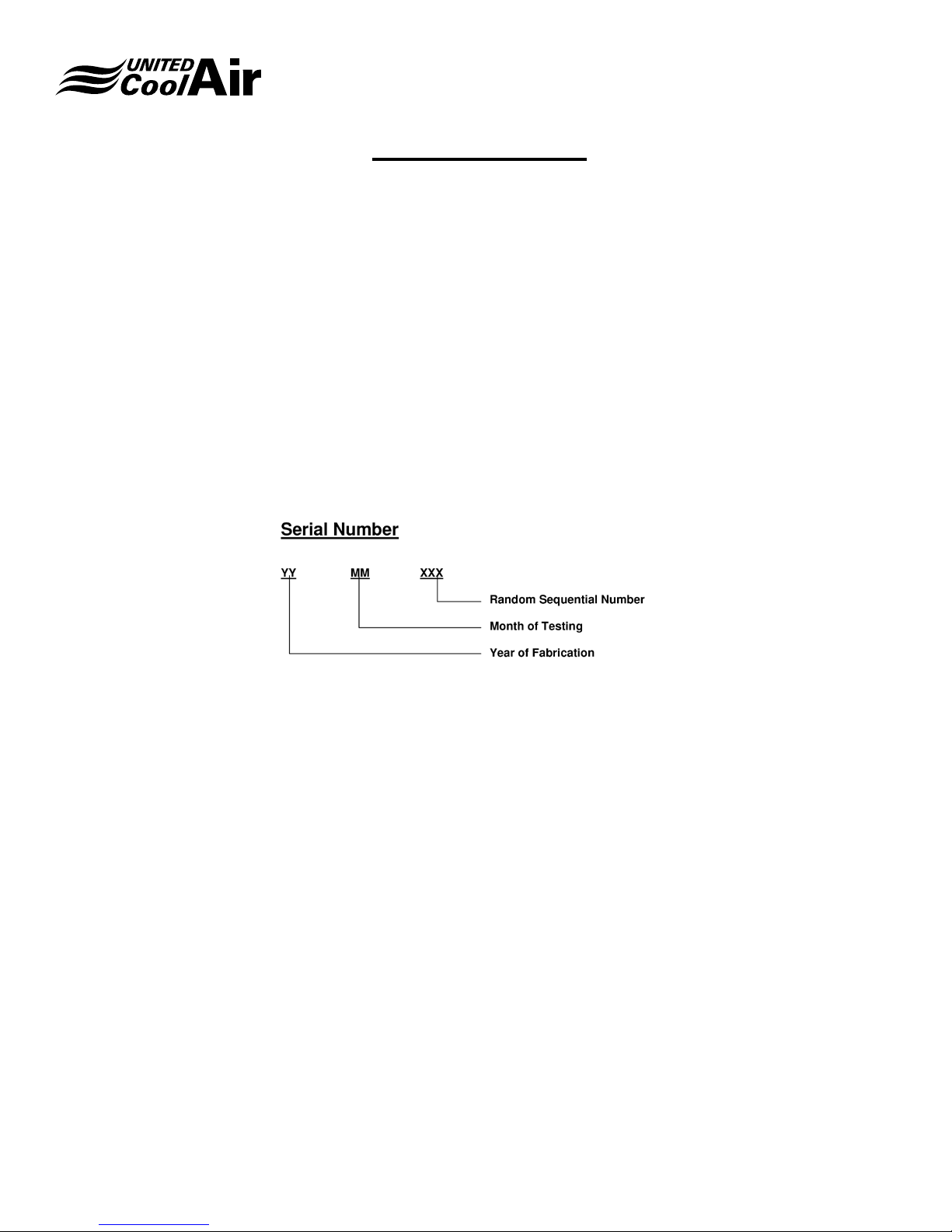
Wiring Diagram
United CoolAir provides a wiring schematic for each unit produced. To retrieve the diagram for your unit please visit
www�unitedcoolair�com, on your computer or mobile device, scroll to the footer section or Home/industry-resources,
enter your serial number in the Serial Search eld and press return to retrieve your product-wiring diagram.
Your serial number is a combination of the year, month and sequential order of build date.
This action will return the Model number, Job Number and the wiring diagram for viewing as well as downloading.
NOTE: Only units shipped since November 2016 are available on the site, for older units please contact the factory directly
at 717-843-4311.
Subject to change without notice. 10.20-IM (0818)
4
Installation, Operation and Maintenance Manual
Important Notice
This manual is the property of the owner�
Please be sure to leave it with the owner when you leave the job�
VariCool® VAV
NOTE: If the unit design was ordered specic to the
application or installation, please refer to the Addendum
at the end of this product literature� The unit may have
features or options specic to this job or application so
please refer to the addendum for details� The addendum
will also list the specic United CoolAir Job Number
or eld reference Job Name. Examples of unit design
specic to unit ordered will include product dimensions,
special control sequences and remote condenser /
condensing sections�
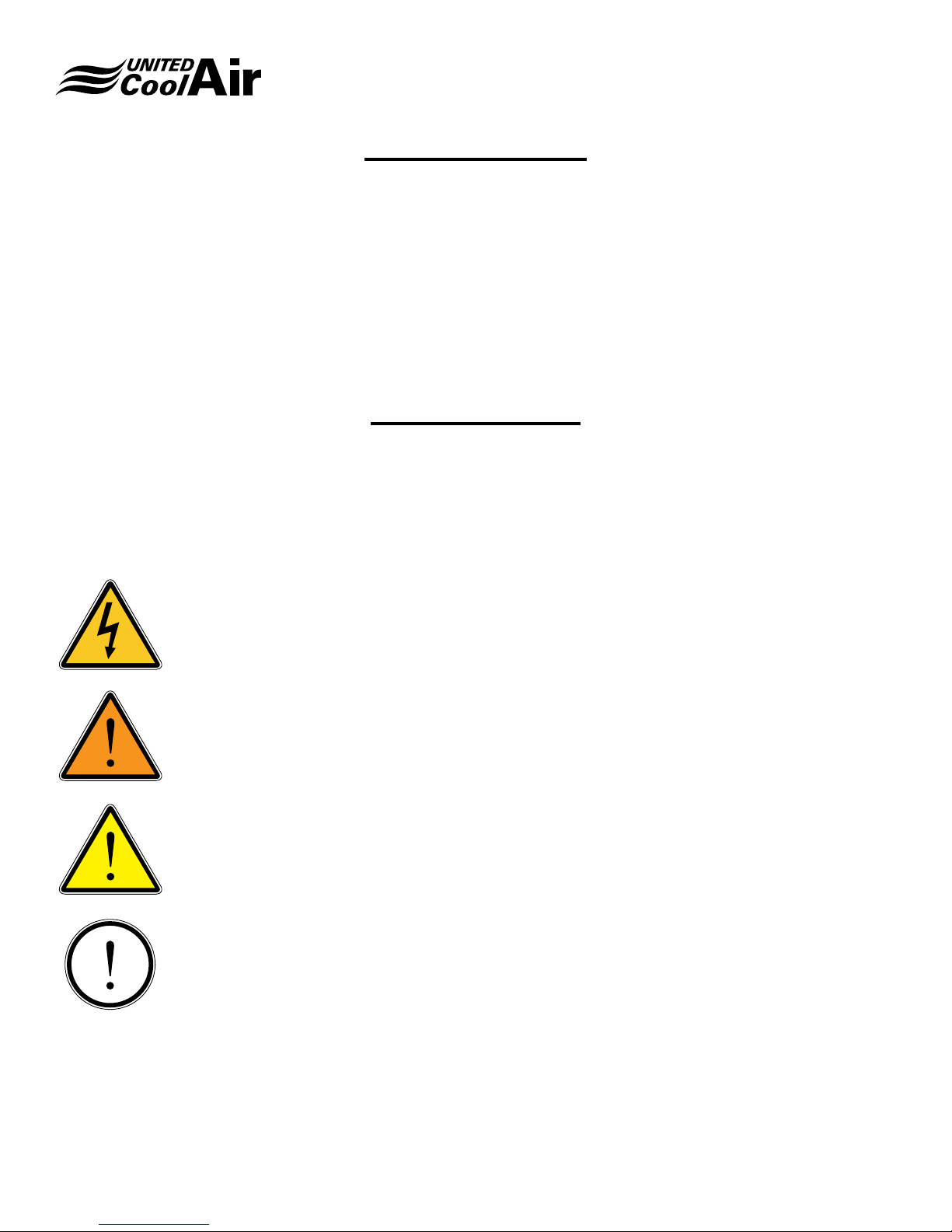
Use of Symbols
This publication includes warnings, cautions and information icons that point out safety related issues or conditions as well
as other pertinent information relative to a safe installation, service or maintenance situation. The following icons should be
interpreted as follows:
ELECTRICAL
HAZARD
WARNING
The electrical hazard icon indicates the presence of an electrical hazard which
could result in electrical shock or death.
The warning icon indicates a potentially hazardous situation which could result
in death or serious bodily injury if not avoided.
CAUTION
INFORMATION
Subject to change without notice. 10.20-IM (0818)
The caution icon indicates a potentially hazardous situation which may result in
minor or moderate injury if not avoided.
The information icon indicates a situation that may result in equipment or
property damage. The information provided alerts the reader to relevant facts
and/or conditions.
5

Installation, Operation and Maintenance Manual
General Information
VariCool® VAV
VariCool units are cooling and optional heating systems
designed to effectively and efciently maintain tenant
occupied spaces within oor by oor building structures.
Each VariCool unit delivers continuous air ow at varied
air volumes and constant temperature to maintain tenant
occupied space settings through eld supplied VAV terminal
outlet boxes. Each unit is designed for optimal energy
efciency, reliability, IAQ, and lowered sound levels. Each
occupant then controls their specic zone by adjusting
temperature setting allowing the VAV terminal outlet box to
open to provide conditioned air. As the VAV box opens, the
VariCool automatically adjusts to maintain the systems static
pressure set point.
Multiple VariCool Systems may be networked together for
unit lead lag, back up/assist, and system rotation. Options
are available for linking each system through a facilities
Building Management System (BMS).
Each unit is shipped in two/three pieces (depends on model
size) for ease on movement to the location of installation.
EQUIPMENT INSPECTION
Upon receiving the unit, carefully inspect all sections for visible
or concealed interior/exterior damage. If damage occurred
during transit, contact the freight carrier immediately and le
a damage claim report. Inspect the unit data plate to verify
that the model unit that was ordered is the correct unit being
received. All accessory components for the application that
must be eld installed are shipped loose in one or several
boxes in the compressor section.
may be moved to the location of installation by crane, fork lift,
hand truck, or roller bars. Units are provided with lifting rings
for rigging and movement by crane. Spreader bars must be
used to protect section cabinet structure during movement.
Protection must be used so that damage to the cabinet
does not occur when using cables or slings. Be certain each
section is well supported when moving. When using dollies,
fork lifts, hand trucks, or roller bars, make sure the sections
base rails are well supported and the weight of the sections
are distributed evenly so that dropping or damage does not
occur during movement.
LOCATION AND CLEARANCES
The unit should be installed in an equipment room located
away from occupied tenant spaces. Careful consideration
should be taken during system layout and installation to allow
for minimum required service clearances for the VariCool
unit. Minimum clearances provided are worst case scenario.
If the clearances were less around the cooling coil section
and a cooling coil had to be replaced, it would be difcult to
maneuver the coil around the unit unless a service access
door(s) to the mechanical room were located next to the
VariCool’s cooling coil end. Figure 1 – Service Clearances
and Table 1 show minimum clearance requirements for each
model unit. If the unit has an optional water side economizer
coil, the distance for service clearance must be maintained
from the edge of the lter rack which will mount onto the
economizer section on larger units but DX cooling coil
on smaller units as the economizer coil will be mounted
internally on smaller systems.
HANDLING
Use extreme caution so that damage does not occur when
moving each section to the location of installation. The unit
Subject to change without notice. 10.20-IM (0818)
6
Installation, Operation and Maintenance Manual
VariCool® VAV
FIGURE 1 – Service Clearances
TABLE 1- SERVICE CLEARANCES
Unit Model (A) Dim (B) Dim
AV*8 – AV*16 30” 30”
AV*20-AV*30 42” 36”
AV*32-AV*60 50” 36”
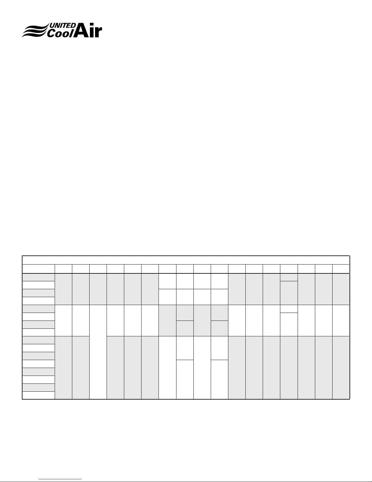
UNIT DIMENSIONS
Figure 2 – Unit Dimensions and Table 2 show the dimensions
of each unit section. Note: If the System has the Water Side
Economizer Coil option, the unit will have a fourth section
that will be attached onto the Cooling Coil/Return Air Inlet
end of the unit. This has been labeled with the dimension
Tx on the diagram and it will vary depending on the lter
options desired.
Subject to change without notice. 10.20-IM (0818)
7
Installation, Operation and Maintenance Manual
VariCool® VAV
FIGURE 2 – Unit Dimensions
TABLE 2 – Unit Dimensions
MODEL A B C D E F G H I J K L M N P R S
AV*08
AV*10
AV*16
AV*20
AV*24
AV*30
68 68 32 32 38 30
80 80
35 48 32 20
16 26 8 21
18 32 7 18
36
7.5
44 18
AV*32
AV*36
AV*40
AV*44
AV*48
AV*52
35
98 100 52 62 36 30
42
11
52 24
AV*56
AV*60
Tx – Filter Rack dimensions are as follows:
T1 – 7” width when a standard 2” Filter is ordered
T2 – 9.5” width with extra ltration option includes a 2” plus 4” lter back to back
TBD TBD 21.5
22
TBD TBD 21
29
1.5 97 4 80 10.5 4.5 86
20
TBD 5 50
40AV*12
40
TBD 5 66
60AV*26
Subject to change without notice. 10.20-IM (0818)
8
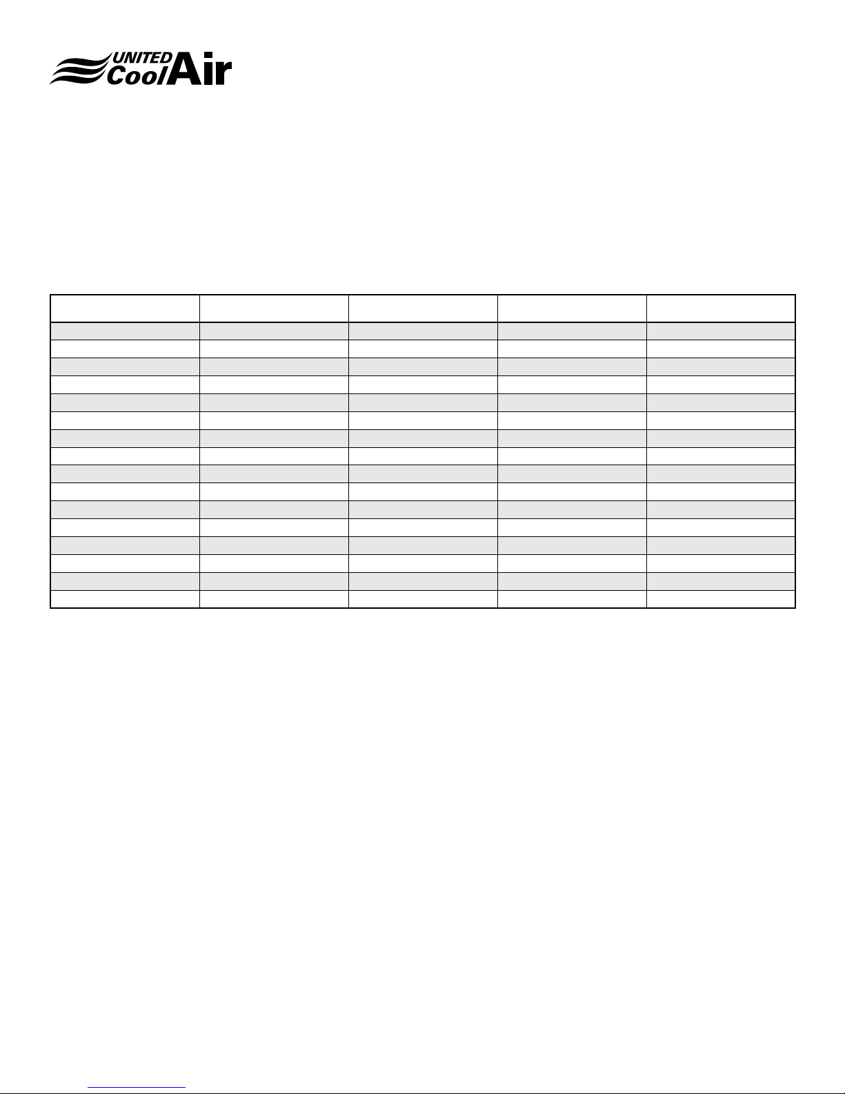
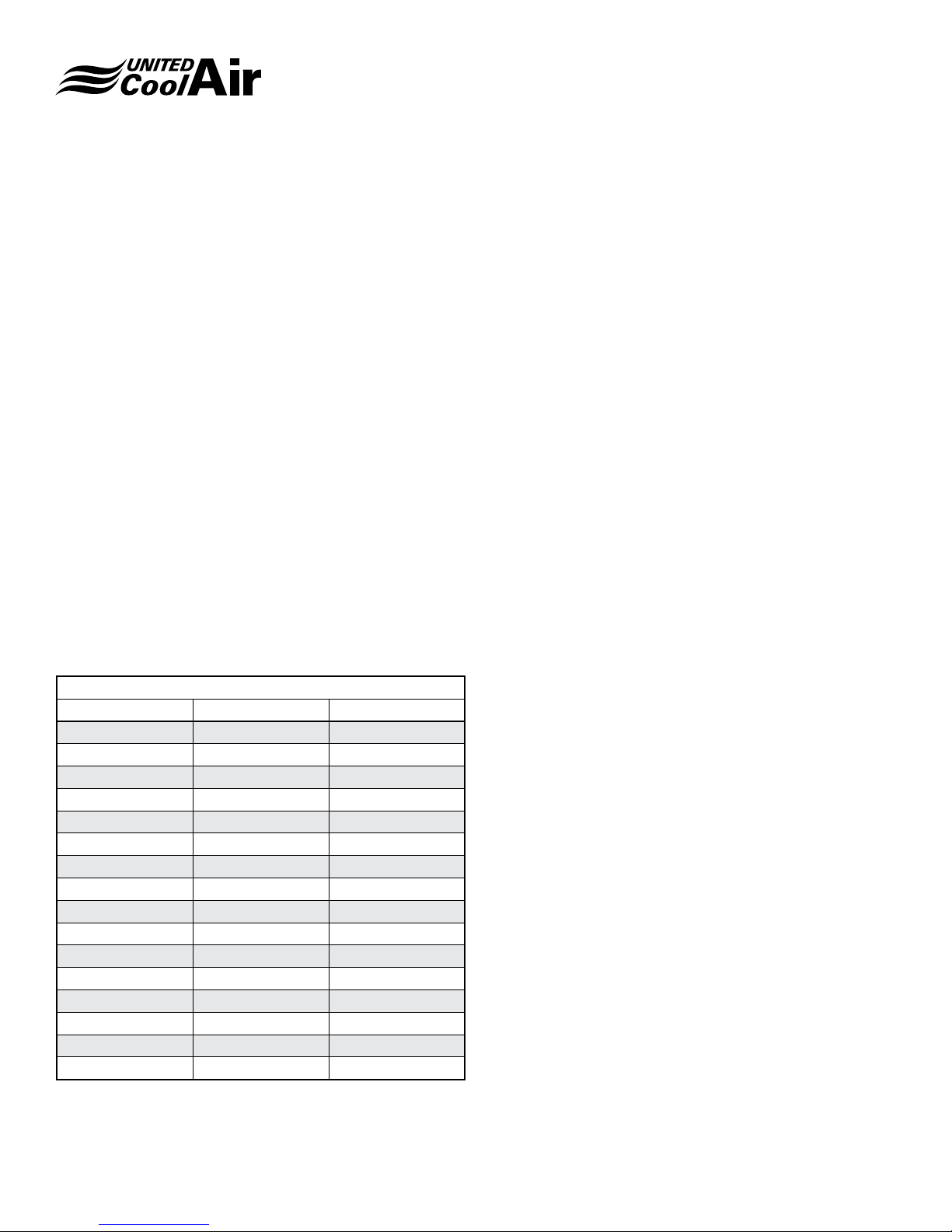
UNIT WEIGHT
Table 3 – Unit Weight shows the weights of each model. The
weight of each unit is listed as a standard VariCool without
options. Table 4 – Optional Component Weight references
the weights of each optional component or upgrade package.
MODEL BLOWER (lbs) EVAPORATOR (lbs) CONDENSER (lbs) TOTAL (lbs)
AVW08 588 521 592 1701
AVW10 617 550 642 1809
AVW12 699 562 732 1993
AVW16 757 619 796 2172
AVW20 1134 856 910 2900
AVW24 1270 954 1046 3270
AVW26 1305 954 1196 3455
AVW30 1305 989 1216 3510
AVW32 1735 1256 1697 4688
AVW36 1787 1325 1673 4785
AVW40 1805 1387 1847 5039
AVW44 1953 1422 1899 5274
AVW48 1953 1479 1942 5374
AVW52 2087 1489 2227 5803
AVW56 2155 1535 2247 5937
AVW60 2155 1593 2287 6035
Installation, Operation and Maintenance Manual
VariCool® VAV
When calculating the weight for each unit, the weight of each
optional component must be added to the standard VariCool
unit weight shown in Table 3.
Table 3 – Unit Weight
Subject to change without notice. 10.20-IM (0818)
9

Installation, Operation and Maintenance Manual
VariCool® VAV
UNIT INSTALLATION
Install the unit using the following procedures. Consideration
must be taken for proper condensate drain installation. Slight
elevation of the VariCool unit may be required for installation
of the condensate drain. Methods for elevating the VariCool
units are support rails, concrete pad(s), or spring isolators.
1� Once the unit’s sections have been moved to the
location of installation, locate the factory provided
mounting hardware, which has been pre-installed in the
holes where the sections will be connected together.
2� Using the appropriate size wrenches, remove the
mounting hardware and set in a safe location for
connecting the sections together during installation.
Vibration Absorbers
When installing the VariCool on a concrete pad, support
rails, or other methods other then spring isolation, use of
vibration absorbers is recommended to prevent transmission
of possible vibration.
3� Figure 3 – Vibration Pads shows the recommended
points for vibration absorbent pads (eld provided). We
recommend the use of a minimum 1” thick Neoprene
vibration absorbent pad under each point shown in
Figure 3. Models AV*09 through AV*16 only require the
pads under the corners only.
4� Place each vibration isolator into positions shown in
Figure 3, and then move the compressor and cooling
coil section into the location of installation being careful
not to damage the quick connect refrigerant piping.
5� Fasten the cooling coil section bottom half to the
compressor section using the mounting hardware
removed in Step 2.
6� Allow the hardware to remain only hand tight until the
Blower Section is installed.
INFORMATION
IMPORTANT: Before proceeding with
the installation of the Supply Air Blower
Section, we recommend connecting the
refrigerant quick connect connections
otherwise it may be difcult to make the
connections.
Refrigerant Connections
The DX Cooling Coil section refrigerant circuit is connected
to the compressor/condenser section using quick-connect
refrigerant connections. If the VariCool unit is a split system
with a Remote Air Cooled Condenser, refer to the section on
Split Systems. If the VariCool was ordered as a packaged
system, connecting refrigerant tubing will be fairly simple.
The quick connect ttings are self-sealing so they do not
permit refrigerant ow until they are completely tight. Follow
these steps for a packaged system:
7� Remove the caps on the quick connect refrigerant
lines.
8� Using a small amount of National 150 or 3G brand
refrigerant oil, lightly lubricate the threads of the
quick connect ttings. (5 to 6 droplets of oil are
recommended)
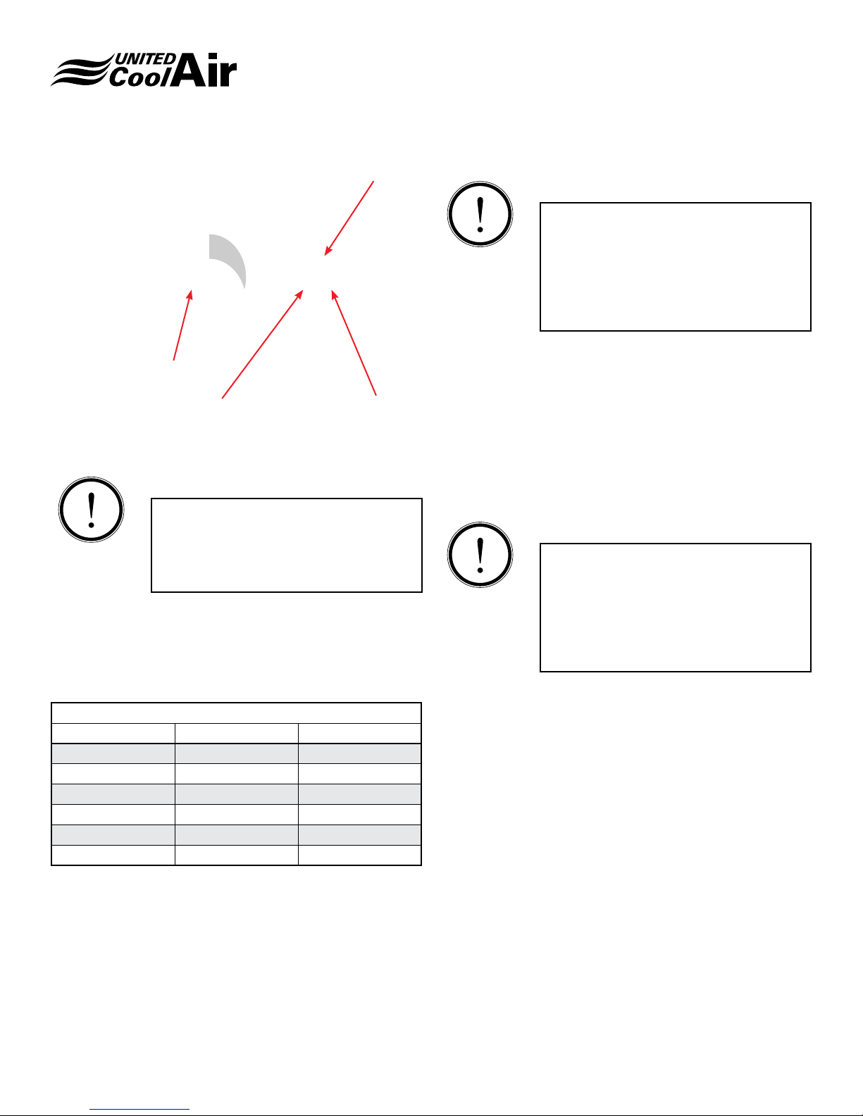
9� Align each quick connect tting and hand thread the
Female Quick Connect ttings onto the Male Quick
Connect ttings as shown in Figure 4 – Quick Connect.
FIGURE 3 – Vibration Pads
Subject to change without notice. 10.20-IM (0818)
10
Installation, Operation and Maintenance Manual
VariCool® VAV
Female Fitting
Clockwise Rotation
Apply oil to male threads
Male Fitting
FIGURE 4 – Quick Connect
INFORMATION
NOTE: Be certain to count the number
of complete thread rotations. Observe
the number of turns reference Table 6 to
determine how tight to make the quick
connect couplings
10� Continue to hand thread until slight resistance is
observed.
11� Once slight resistance is evident, continue to tighten
the ttings using appropriate size wrenches listed in
Table 5.
TABLE 5
QC-Size Wrench # Full Turns
3/8” 1-3/16” 6
1/2” 1-3/16” 6
5/8” 1-5/8” 7-3/4
3/4” 1-5/8” 7-3/4
7/8” 1-5/8” 8
1-1/8” 2” 8
12� If the quick connect still feels loose, tighten just a bit
more until complete resistance is evident.
INFORMATION
NOTE: Once tight, refrigerant should be
able to pass through the quick connect
couplings. If problems with low refrigerant
pressure appear during system startup,
double check the tightness of these quick
connect couplings as loose ttings will
restrain full refrigerant ow.
13� Move the Blower Section into position of installation
making sure the side that the blower can be seen will
mate up with the large opening in the Cooling Coil
Section.
14� Lift the blower section up onto the Compressor Section.
15� Use the remaining mounting hardware to connect the
Blower Section to the Cooling Coil Section.
16� Using the appropriate size wrenches, hand-tighten all
mounting hardware.
INFORMATION
Note: seismic isolators are shipped
completely locked into position. Once
the blower section is installed the spring
isolators adjusted to loosen the blower on
isolators. The blower should be allowed to
oat on the isolators approximately ½" to
1" side to side and back and fourth.
17� Once the supply air blower is installed, the spring
isolators under the supply air blower must be
loosened. It is the responsibility of the installing
contractor to loosen the spring isolators. These
isolators are tightened for shipping purposes only.
They must be loosened for proper operation.
Subject to change without notice. 10.20-IM (0818)
11
Installation, Operation and Maintenance Manual
VariCool® VAV
Duct Connections
A supply air plenum must be eld fabricated and attached
to the supply air outlet with a exible duct collar. Follow
appropriate guidelines for typical ducting installation.
Provide a duct length that is 3 to 4 times the diameter of
the plug fan wheel before making the rst transition. Provide
turning vanes when required. Attach the supply air plenum
Water Piping / Water Flow
As a standard, units shall have a shell and tube water cooled
condenser. The end plates of the shell and tube condenser
are fully removable for brush cleaning when soft deposits or
scale have formed internal to the condenser coil. Table 6 lists
the water ow and water pressure drops for each model unit.
Tube and tube water cooled condensers may be substituted.
Water Connections
Do not reduce water inlet and outlet connections as this will
restrain water ow and increase water pressure. The inlet
water line should have a strainer accessible for periodic
cleaning. Both the inlet and outlet water lines should have
eld installed water shut-off valves (Gate or Ball type valves).
The shutoff valves are required for maintenance, system
repairs, or long periods of system shut down.
TABLE 6 – Flow Rates/PSI Drop
Model GPM PSI
AVW8 24 4
AVW10 30 6
AVW12 36 7
AVW16 48 8
AVW20 60 6
AVW24 72 8
AVW26 78 10
AVW30 90 14
AVW32 96 8
AVW36 108 10
AVW40 120 6
AVW44 132 7
AVW48 144 8
AVW52 162 10
AVW56 168 12
AVW60 180 14
Recommended Field Installed
Externally
Condensate Drain Connection
Each VariCool unit has a condensate drain connection on
the Cooling Coil section. For systems with the Water Side
Economizer coil option, condensate drain connections are
provided
A condensate drain trap must be eld fabricated and
installed onto the 1" IPS drain connection. Each trap must
then be piped to a common waste drain. Refer to Figure
5 – Condensate Trap for reference dimensions. Units are
equipped with a 1" male IPS connection.
For systems with the Water Side Economizer coil option,
each individual section (Cooling Coil and Water Side
Economizer sections) must be piped individually with a
separate drain trap. Once each section has a drain trap, they
may be connected together by a tee and piped to a common
waste drain.
The depth of the condensate trap will vary due to the model of
the unit ordered and eld requirements. The purpose of the
trap is to neutralize the negative pressure created within the
blower cabinet. Refer to the order specications for external
static pressure (ESP) to calculate the depth required for the
“A” Dimension shown in Figure 5. The A Dimension must
equal or exceed the negative pressure developed by the
supply air blower. If it does not, the condensate will not drain
properly and may allow the drain pan to overow. The lower
leg of the trap must maintain a minimum depth of 3-1/2” to
maintain a water seal on during all operating conditions.
Plug each section’s (Cooling Coil and optional Water Side
Econo Coil) opposite side drain connection as shown.
Subject to change without notice. 10.20-IM (0818)
12
FIGURE 5 – CONDENSATE TRAP
ELECTRICAL CONNECTIONS
All electrical wiring must be in accordance with NEC (National
Electrical Code) and state and local building codes. Refer to
the specications section or the unit’s data tag for the unit’s
power requirements. The main power entrance for each
VariCool unit is located directly above the electrical box.
SINGLE POINT DISCONNECT (OPTION)
If the VariCool unit has through the door single point power
disconnect option, turn the disconnect switch to the ON
position.
SERVICE DISCONNECT
A eld installed fused single point power service disconnect
is required. Install the service disconnect in accordance
with NEC, State, and Local building codes. NEC guidelines
require the unit’s disconnect be installed within sight of the
unit.
A factory provided power block is installed internal to the
VariCool’s electrical control panel. Route the main power
wires in accordance with electrical codes to the eld provided
unit disconnect and terminate them on the line side of the
disconnect. Route the power wires from the Load side of
the eld provided service disconnect to the unit power block
inside the electrical panel.
A ground termination point is located within the VariCool’s
electrical control panel.
Installation, Operation and Maintenance Manual
VariCool® VAV
INFORMATION
NOTE: Conduit is not an acceptable
ground source. A separate ground conduct
must be connected from Earth Ground to
the factory supplied ground lug internal to
the unit.
SENSOR FIELD MOUNTING & WIRING
All sensors and optional components that must be eld
installed and wired to the electrical control panel must be
wired as shown on the electrical diagram provided with the
unit and the instructions listed below.
Static Pressure Transducer
The static pressure transducer is factory installed internal to
the main electrical panel and wired back to the main control
board. Pneumatic tubing (eld supplied) must be connected
from the “HIGH” connection to a point approximately 2/3rds
the distance down the straightest length of supply air ducting.
NOTE: Make certain there are no kinks in the pneumatic
tubing.
1� Drill a hole into the ducting at a right angle. Place
approximately 1/8” of the high pressure tube into the
duct at a right angle. The end of the pneumatic tubing
must be cut at and make a right angle for the tube to
pick up the correct air pressure reading.
2� Use a clamp to secure the tube to the ducting.
3� Make certain the end of the tube is cut ush at a 90
degree right angle. This tube must be located in
ambient air.
The static pressure transducer is preset to read from 0”
to 2.5” W.C. The VariCool’s controller will read the preset
conguration. If a lower pressure conguration is desired,
use the manufacturer’s provided literature to re-congure for
the sensor to read the desired lower pressure setting.
INFORMATION
NOTE: The VariCool’s controller for sensor
calibration must also be readjusted. This
is explained under sensor calibration in
the Marvel Plus controller section.
Subject to change without notice. 10.20-IM (0818)
13
 Loading...