

UNITED 5500 Installation & Maintenance Manual
INSTALLATION
MODEL 5500- Wall Indicator Post
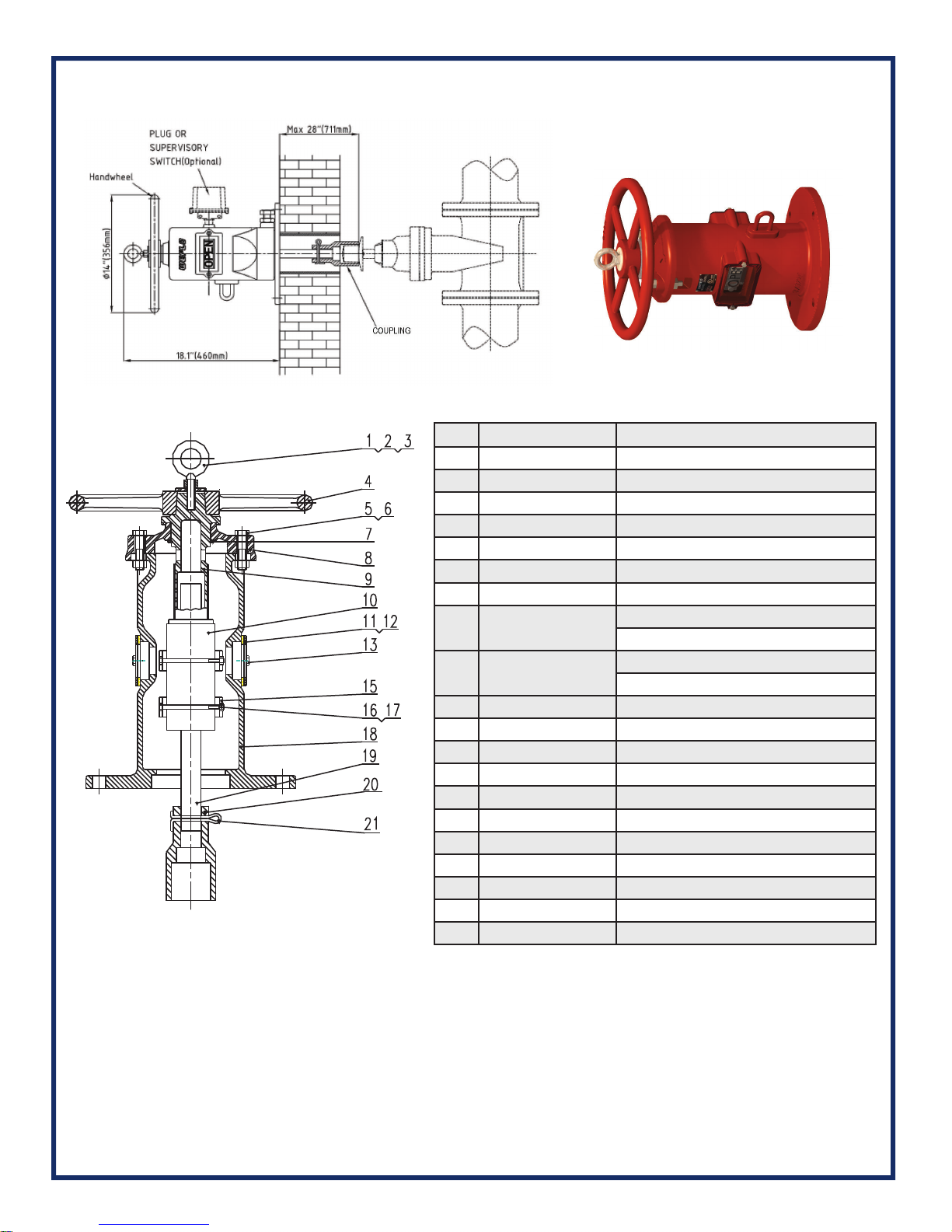
MATERIAL LIST
1 Eye Bolt Carbon Steel ASTM A307B
2 Hex Nut Carbon Steel ASTM A307B
3 Washer Carbon Steel ASTM A570 Gr 33
4 Handwheel Ductile Iron ASTM A536 Gr 65-45-12
5 Hex Cap Screw Carbon Steel ASTM A307B
6 Square Nut Carbon Steel ASTM A307B
7 Snap Ring Stainless Steel AISI 1066
8 Cover Cast Iron ASTM A126 Class B
9 Operating Nut
10 Target Carrier Nut
11 Window Glass Plexiglass
12 Gasket PTFE
13 Hex Nut Carbon Steel ASTM A307B
14 Plug Malleable Iron
15 Target Cast Aluminum
16 Hex Cap Screw Carbon Steel ASTM A307B
17 Hex Nut Carbon Steel ASTM A307B
18 Body Cast Iron ASTM A126 Class B
19 Stem Carbon Steel AISI 1045
20 Crane Coupling Ductile Iron ASTM A536 Gr 65-45-12
21 Cotter Pin Stainless Steel AISI 304
Bronze ASTM B62 C83600
Stainless Steel AISI 304
Bronze ASTM B62 C83600
Stainless Steel AISI 304
NOTE: Ensure that the non-rising stem gate valve is in the fully open position before installing the
Wall Post Indicator.
1. Make the Walk Through Hole
Make a clearance hole that is at least 4.7” (120mm) in diameter but not greater than 180MM (7.1”)
in diameter through the mounting wall. The clearance hole must be on-center and concentric with
the operating nut of the non-rising stem gate valve. NOTE: A 4” / DN100 (114.3mm Outside Diameter) length of pipe can be used to line the inside of the through hole. Pipe of this diameter will
fi t snugly into a machined mating hole on the fl ange side of the Body (18) of the Wall Post Indicator.
 Loading...