

UNITED 3900F Series, 3900M, 3900MJ Series Installation & Maintenance Manual

AWWA C504
Series 3900F - Flanged with Handwheel or Lever Handle
Series 3900MJ - Mechanical Joint with Handwheel or Lever Handle
1218
MODELS 3900F & 3900M - Butterfl y Valve with Manual Gear Operator
GENERAL
Butterfl y valves are a signifi cant component of any water distribution system or treatment plant operation. Valve
failure caused by faulty installation, improper operation, or maintenance in these systems could result in damage, downtime, and costly repairs. In buried or underground installations, problems or malfunctions can result in
extensive an costly excavation to correct or eliminate the problem. Many problems with butterfl y valves can be
traced to improper installation, or maintenance procedures.
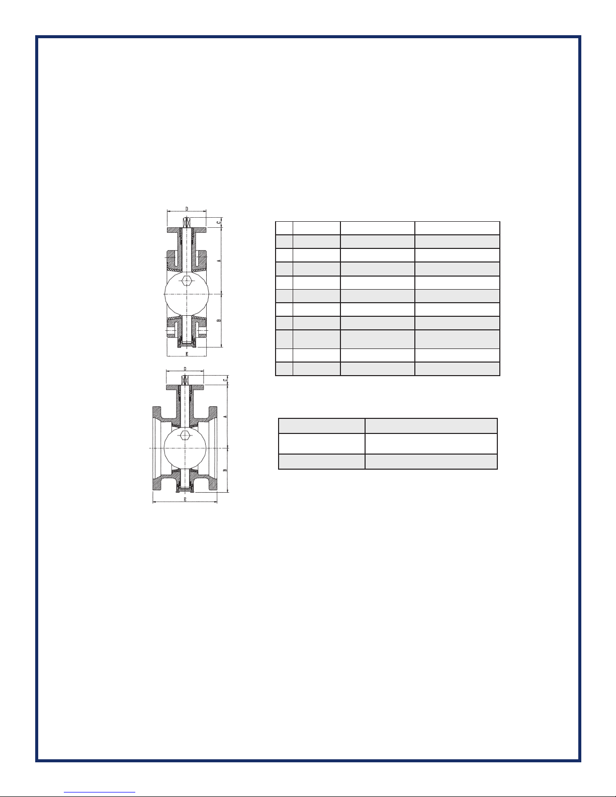
MATERIAL LIST/PRESSURE AND TEMPERATURE:
No. Part Name Material ASTM Spec.
1 Stem Stainless Steel AISI 420
2 Spacer Brass ASTM B16 C36000
3 Packing EPDM or NBR -
4 Bushing Brass ASTM B16 C36000
Flange x Flange
5 Body Ductile Iron ASTM A536 65-45-12
6 Bearing Tefl on -
7 Seat EPDM or NBR -
8 Disc
9 Cover Plate Ductile Iron ASTM A536 65-45-12
10 Lock Washer Carbon Steel AISI 1045
Ductile Iron
(with SS316 Edge)
ASTM A536 65-45-12
Nominal Pressure 250 Psi
MJ x MJ
Working Temperature
Suitable Media Water, Oil, Gas
EPDM: -10°C to 120°C
NBR: -10°C to 82°C
UNLOADING
Inspect valves on receipt for damage in shipment and conformance with quantity and description of the shipping notice and order. Unload valves carefully to the ground without dropping them. On valves larger than 16 in. (400mm), use forklifts or slings
under the skids. On smaller valves, do not lift valves with slings or chain around the operating shaft, actuator, or through the
waterway. Lift these valves with eye bolts or rods through the fl ange holes.
STORAGE
If it is not practical to store a valve indoors, protect the valve and actuators from weather; the accumulation of dirt, rocks and
debris. When valves fi tted with power actuators and controls are stored, energize electric actuators or otherwise protect electrical-control equipment to prevent corrosion of electrical contacts caused by condensation resulting from temperature variation. Do not expose rubber seats to sunlight or ozone for any extended period.
INSPECTION PRIOR TO INSTALLATION
Verify fl ange faces, joint-sealing surfaces, body seats, and disc seats are clean. Verify the bolts attaching an actuator to a
valve are tight, and if loose, tighten fi rmly. Open and close a valve to verify it operates properly and that stops or limit switches
are correctly set so that the valve seats fully. Close a valve before installing it.
 Loading...