

Page 1
Technical Manual
UNITECH INSTRUMENTS
UNITECH makes the indication and control of
Process Parameters
+91 94273 01436
Sales: Email :
www.unitechinstrument.com
Website:
“Sure for service with hi-end versal nology”Uni Tech
info@unitechinstrument.com
Add.-503/504,Helix Complex , Opp. Surya Hotel, Sayajigunj, Vadodra-05. Gujrat. INDIA, PH-0265 6623551
UT-1596/UT-1572/UT-1584/UT-1548
PV
SV
Model :UT 1196
8
88
8 88
8
88
8
88
OUT OFF AT AL1
AL2
PV
SV
Model :UT 1177
8
88
8
88
8
88
8
88
OUT OFF AT AL1 AL2
100%
0%
20
60
40 80
PV
SV
A/M
OUT
AT
AL1
AL2
8
88
8
88
8
88
8
88
Model :UT 1149
PV
SV
Model :UT 1144
OUT
AT
AL1
AL2
8
88
8
88
8
88
8
88
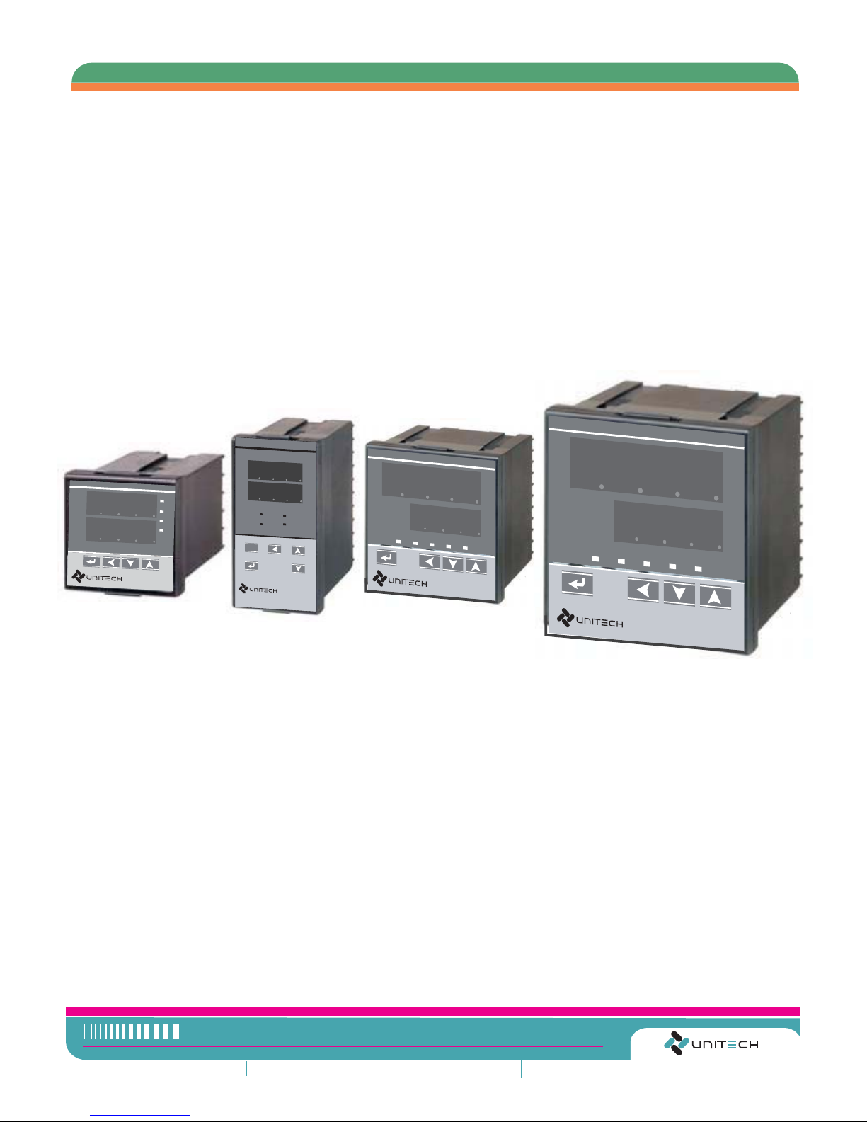
PID CONTROLLERS
Page 2
UNITECH UT - 1596/1572/1584/1548
INSTRUCTION MANUAL Specification
Overview
The UT 15 Series are microprocessor-
based controllers designed with a high
degree of functionality and reliability at a
competitive price. The controllers are
available in different formats: 48x48,
72x72, 96x96 This controller series is
Ideal for the control of temperature,
Humidity, pressure, flow etc.
in a variety of applications including:
z Plastic Processing Industries
z Packaging Machinery
z Painting and coating Plants
z Semiconductor packaging / Testing
z Industrial Dryers
Features
z Easy to Operate
Different configuration levels provide easy
access to parameters.
z Various Control Programming
Several different algorithms are available
as follows:
- PID or ON/OFF Control
- Heat/Cool Control with 2 PID sets
- Motor Position Control
(without slidewire feedback)
z Auto-Tuning Capability
Advanced auto-tuning function calculates
the optimized PID values for your specific
control system.
z
Dual Display and Bar graph
Two large 4 digits display PV, SP and
configuration parameters. One 10 LED
bar-graph displays the control output
(MV), and up to 8 LEDs display the status
of the different outputs (Control, Alarm,
…) and also provide indication of the
Auto/Manual and programmer states.
z Setpoint Programming
Two programs are available with a
maximum of 8 segments. The 2 programs
can be linked together and perform as a
single 16 segment program.
z Extended Alarm Capability
Up to three different alarm outputs are
available per instrument and 17 kinds of
event modes can be assigned to each of
alarm output.
z Communications
RS232 or RS485 (with ASC II & Modbus
RTU Protocol) is optionally available with
a maximum communication speed of
38400 bps.
z
IP65 Front Face Protection
IP65 rated front face permits use in
applications where it may be subjected to
moisture, dust conditions.
z Remote Setpoint Capability
The setpoint can be defined from a
remote PLC or other controller.
z Parameter Lock
A 4-digit security code prevents any
unauthorized changes of parameters or
configurations. Parameters can be hidden
to user to prevent any mis-configuration
of the unit.
DIGITAL PID CONTROLLERS
z And many more......
PV
SV
Model :UT 1596
8
88
8
88
8
88
8
88
OUT OFF AT
AL1
AL2
PV
SV
Model :UT 1177
8
88
8
88
8
88
8
88
OUT OFF AT
AL1
AL2
100%
0%
20
60
40 80
PV
SV
A/M
OUT
AT
AL1
AL2
8
88
8
88
8
88
8
88
Model:UT 1584
PV
SV
Model :UT 1144
OUT
AT
AL1
AL2
8
88 8
88
8
88
8
88
Page 3

Specifications
General
Rated power supply voltage 85 to 265V AC, Frequency : 50/60Hz
22 to 26V AC, Frequency : 50/60Hz (Rating : 24VAC)
Insulation Resistance
OVER 10M UNDER DC500V megger between Input terminal andΩ
Case(Ground).
Ambient Temp..
25 2+
°C
Ambient Humi. 55 ± 5% RH
Rated Power Supply 230V AC, 24V AC, 24VDC
Power Frequency 50 ± 1Hz o± 60 ± 1HZ
Standard
Conditions
Ambient Temp.
0to50°C
Ambient Humi. 20 to 90%RH (non-condensing)
Rated Power Supply 85 to 265V AC
22 to 26V DC
Allowable Power
Supply
85 to 265V AC
22 to 26VDC
Power Frequency 50 ± 2Hz o± 60 ± 2Hz
Operating
Conditions
Ambient Temp.
-20 to +65 °C
Ambient Humi. 10 to +95% RH (non-condensing)
Transportation
and storage
conditions
Vibration Resistance 20m/s
2
(Approx. 2G), 10 to 55Hz for 2 hours each in X, Y, Z directions
Exterior Case and front panel : plastic
Mounting Panel-mount
Model
Exterior Size (unit:
inch
mm
)
:WXHXD
50 X 50 X 97
(1.97X1.97X 3.82)
50 X 96 X 97
(1.97X3.78X3.82)
74 X 74 X 97
(2.91X2.91X3.82)
96 X 96 X 97
(3.78X3.78X3.82)
Panel Cutout (unit:
inch
mm
)
:WXH
44.5 X 44.5
(1.75 X 1.75)
44.5 X 90.5
(1.75 X 3.56)
68.5 X 68.5
(2.97 X 2.97)
90.5 X 90.5
(3.56 X 3.56)
OVER 10M UNDER DC500V megger between Output terminal andΩ
22 to 26V DC (Rating : 24VDC)
UT-1548 UT-1584 UT-1572 UT-1596
Power Consumption 5VA Max (at 24V AC) 160mA max (at 24VDC)
7VA Max (at 100V AC) 10 VA max (at 240V AC)
Case(Ground).
Page 4

1. Specifications
Input/Output
Number of Point 1 point (TC, RTD or Linear)
Type
TC: K,J,R,S,B,E,T
RTD : Pt-100
Linear : 4~20mA / 2~10V DC (500 Resistance connected Across)Ω
Note :
Refer to Table A.
For input Type symbols and Ranges.
Sampling cycle 250 ms
Indication
Accuracy
± 0.2% FS ± 1digit (for details Table1-1)
Cold junction
accuracy
±1.0ºC (under standard conditions)
Input bias (offset) LSPL ~ USPL
Digital Filter 0 - 200 sec (0: filter off)
Analog
Input 1
Decimal Point 0000, 000.0, 00.00, 0.000
0~20mA / 0~10V DC (500 Resistance connected Across)Ω
Output Alarm Output Relay Contact Output : 250V AC, 3A (Resistive Load)
Control Output Relay Contact Output : 250V AC, 3A (Resistive Load)
Voltage Pulse 0/12V DC. (Load Resistance 600 or More)Ω
Current Output 4 to 20mA DC. (Load Resistance 500 or Less)Ω
Trigger Output 100A or LessCurrent Output
(For TRIAC Driving)
2. Mounting
Mounting Cautions :
(1) Use this instrument within the following ambient temperature and ambient humidity.
Allowable ambient temperature: 0 to 50°C
Allowable ambient humidity: 45 to 85% RH
(2) Avoid the following when selecting the mounting location.
Rapid changes in ambient temperature which may cause condensations.
Corrosive or inflammable gases.
Direct vibration or shock to the mainframe.
Water, oil, chemicals, vapour or steam splashes.
Excessive induction noise, static electricity, magnetic fields or noise.
Direct air flow from an air conditioner.
Exposure to direct sunlight.
Excessive heat accumulation.
z
z
z
z
z
z
z
z
z
z
Page 5

External Dimensions
Mounting Procedure
Mounting Cautions :
(1) Use this instrument within the following ambient temperature and ambient humidity.
Allowable ambient temperature: 0 to 50°C
Allowable ambient humidity: 45 to 85% RH
(2) Avoid the following when selecting the mounting location.
Rapid changes in ambient temperature which may cause condensations.
Corrosive or inflammable gases.
Direct vibration or shock to the mainframe.
Water, oil, chemicals, vapour or steam splashes.
Excessive induction noise, static electricity, magnetic fields or noise.
Direct air flow from an air conditioner.
Exposure to direct sunlight.
Excessive heat accumulation.
z
z
z
z
z
z
z
z
z
z
Page 6

1
2
3
4
5
6
7
8
9
10
11
12
13
14
TC
NO
AL 1
UT-1572
L
N
AC 85~265V
RTD
+
VDC
A
B
B
4-20mA
OR
0-20mA
-
+
-
-
+-+
OUT: Relay
NO
NC
C
Voltage for SSR
V, mA, Current
AL 2
NO
NC
C
1
2
3
4
5
6
7
8
9
10
RTD
+
-
VDC
A
B
B
NO
NO
4-20mA
OR
0-20mA
AL 1
OUT: Relay DC4-20mA
-
+-+
UT-1145
L
N
AC 85~265V
+
-
11
12
NO
AL 2
TC
Mounting Procedures
(1) Prepare the panel cutout as specified in 2.2 Dimensions.
(2) Insert the instrument through the panel cutout.
(3) Insert the mounting bracket into the mounting groove
of the instrument. (As Fig.1)
(4) Pull till chick sounds to the direction shown by the arrow.
(As Fig.2)
(5) The other mounting bracket should be installed the same
way described in 3.To 4.
3. WIRING
Wiring Cautions :
Terminal Configuration :
1
2
3
4
5
6
7
8
9
10
11
12
13
14
15
16
17
18
19
20
+
-
RTD
+
-
VDC
TC
A
B
B
NO
NO
4-20mA
OR
0-20mA
AL 1
OUT: Relay DC4-20mA
-
+-+
UT-1584 & UT-1596
L
N
AC 85~265V
AL 2
NO
NC
C
(1) All the under hookups are only for reference.
(2) For wiring, please according to the hookup label which was glued
on the plastic case of controller.
(1) For thermocouple input, use the specified compensation wire.
(2) For RTD input, use leads with low resistance and having no resistance differences among the 3 leads.
(3) Conduct input signal wiring away from instrument power, electric equipment power and load lines to avoid noise
induction.
(4) Conduct instrument power wiring so as not to be influenced by noise from the electric equipment power. If the
instrument may be affected by external noise, a noise filter should be used.
* shorten the distance between twisted power supply wire pitches. The shorter the distance between the pitches,
the more effective for noise reduction.
* Install the noise filter on the panel which is always grounded and minimize the wiring distance between the noise
filter output side and the instrument power terminals.
* Do not install fuses and/or switches on the filter output signal since this may lessen filter effect.
(5) For wiring, use wires conforming to the domestic standard of each country.
(6) About 4 to 5 seconds is required as the preparation time for contact output after power on. Use the delay relay
when the output line is used for an external interlock circuit.
(7) This instrument has no power supply switch nor fuses. Therefore, install the fuse close to the instrument and the switch,
if required.
* Recommended fuse rating: Rated voltage; 250 V Rated current; 1A * Fuse type; Time-lag fuse
(8) Do not excessively tighten the terminal screws. In addition, use the solder less terminal appropriate to the screw size.
(9) To the instrument with power supply of 24V, please be sure to supply the power from SELV circuit
Page 7

4. FRONT DESCRIPTION
5. SETTING
Page 8

Page 9

Page 10

6. PID Autotuning (AT) Function
7. Error Display
08. Selection Table
Code
Type
Special
T
–
None
Relay
SSR
S
N
R
1
Code
2
1
2
3
4
1
2
3
4
1
Code
Type
96X96
96X48 (V)
72X72
96
72
84
Code
Type
Special
T
–
None
4-20mA
0-10/5V
V
N
C
1
Code
2
1
2
1
2
1
Code
Type
NONE
RS-232
RS-484
GSM
N
4
M
2
UT-15
XX
X
X
X
X
X
Size CNT. Output RTS.output
Com.
48X48
48
 Loading...