

Page 1

‐1‐
unitech
RP901
Wireless UHF RFID Pocket Reader
User’s Manual
V1.9
2017 / 1/ 12
Page 2

‐2‐
‐ Table of Contents ‐
1. Introduction
............................................................................................................................................................
4
1‐1. Product Features
..........................................................................................................................................
4
1‐2. Package Contents
.........................................................................................................................................
5
1‐3. Product Characteristics and Specifications
....................................................................................................
5
1‐3‐1. RFID Tag Supported by the RP901
......................................................................................................
5
1‐3‐2. RP901 Product Specifications
.............................................................................................................
6
1‐3‐3. RP901 Indicator Lights and Sounds
....................................................................................................
7
1‐4. Operating Instructions
.................................................................................................................................
8
1‐4‐1. Power Up
...........................................................................................................................................
8
1‐4‐2. Shut Down
.........................................................................................................................................
8
1‐4‐3. Connecting to a PC/ Notebook
...........................................................................................................
9
1‐4‐4. Connecting to an Apple iOS Device
..................................................................................................
12
1‐4‐5. Connecting to an Android Device
.....................................................................................................
15
1‐4‐6. Reading RFID Tags
...........................................................................................................................
18
1‐4‐7. Clearing the Bluetooth Pairing Record
............................................................................................
20
1‐4‐8. Retrieving/Del eting Memory Data
.................................................................................................
21
2. Configuration Mode
...............................................................................................................................................
25
2‐1. Entering Configuration Mode
......................................................................................................................
25
2‐2. Canceling / Exiting Configuration Mode
.....................................................................................................
26
3. Operating the RFID Utility
......................................................................................................................................
27
3‐1. Introduction to Main Window
....................................................................................................................
27
4. RFID Parameters Setup
..........................................................................................................................................
29
4‐1. Operation Mode
.........................................................................................................................................
29
4‐2. Read Mode
...................................................................................................................................................
30
4‐2‐1. Single‐Tag Read or Multi‐Tag Read
..................................................................................................
30
4‐2‐2‐1. Session
..........................................................................................................................................
31
4‐2‐2‐2. Target
............................................................................................................................................
31
4‐2‐3. Tag Info ‐ Memory Banks in Single‐Tag Read mode:
........................................................................
31
4‐2‐4. CRC Value
.........................................................................................................................................
32
4‐2‐5. User Memory ‐ Memory Bank in Single‐Tag Read mode:
................................................................
32
4‐2‐5‐1. Access Password
...................................................................................................................
32
4‐2‐5‐2. Starting Pointer and Data Length
..........................................................................................
32
4‐2‐6. Tag Info ‐ Memory Bank in Multi‐Tag Read mode:
..........................................................................
33
4‐2‐7. Tag‐List Counter
...............................................................................................................................
33
4‐3. Scan Period and Delay Time
........................................................................................................................
33
4‐3‐1. Scan Period
.....................................................................................................................................
33
4‐3‐2. Delay Time
........................................................................................................................................
34
4‐4. Scheme and Filter
.........................................................................................................................................
35
4‐4‐1. EPC Schem e
.......................................................................................................................................
35
4‐4‐2. Accepted Filter
.................................................................................................................................
35
4‐4‐3. Rejected Filter
..................................................................................................................................
36
4‐4‐4. Affected Scheme of Filters
...............................................................................................................
36
4‐5. RF Parameters
..............................................................................................................................................
37
4‐5‐1. RF Output Power
...............................................................................................................................
37
4‐6. Data Output Format
...................................................................................................................................
38
4‐6‐1. Output Format
..............................................................................................................................
39
4‐6‐2. Time Log
...........................................................................................................................................
39
Page 3

‐3‐
4‐6‐2‐1. Output Time Log’s caption “Time Log:”
..............................................................................
39
4‐6‐3. RSSI (Received Signal Strength Indicator)
........................................................................................
40
4‐6‐3‐1. Output RSSI 's caption “RSSI: ”
..............................................................................................
40
4‐6‐4. EPC Scheme
......................................................................................................................................
40
4‐6‐4‐1. Output EPC Scheme caption “EPC Scheme:”
........................................................................
41
4‐6‐5. EPC Code
...........................................................................................................................................
41
4‐6‐5‐1. Output EPC Code’s caption “EPC Code:”
...............................................................................
41
4‐6‐6. PC (Protocol Control)
.......................................................................................................................
42
4‐6‐6‐1. Output PC data's caption “PC:”
............................................................................................
42
4‐6‐7. CRC (Cyclic Redundancy Check)
.......................................................................................................
42
4‐6‐7‐1. Output CRC value's caption “CRC:”
......................................................................................
43
4‐6‐8. TID data
.............................................................................................................................................
43
4‐6‐8‐1. Output TID data's caption “TID:”
..........................................................................................
43
4‐6‐9. User Memory
....................................................................................................................................
44
4‐6‐9‐1. Output User Memory 's caption “USER memory:”
...............................................................
44
4‐6‐10. Error‐Message
................................................................................................................................
44
4‐6‐11. No‐Ta g‐Message
.............................................................................................................................
45
5. Other Parameters Setup
........................................................................................................................................
46
5‐1. Date Format
................................................................................................................................................
46
5‐2. Time Format
.......................................................................................................................................
47
5‐3. Communication Interface
...................................................................................................................
48
5‐4. Memory Communication Interface Options
................................................................................................
49
5‐4‐1. Field Separator
................................................................................................................................
49
5‐5. BT‐HID and BT‐SPP Communication Interface Options
................................................................................
49
5‐5‐1. BT ‐ID
.................................................................................................................................................
49
5‐5‐2. BT‐Pin‐Code
......................................................................................................................................
49
5‐6. USB‐HID and BT‐HID Communication Interface Options
..............................................................................
50
5‐6‐1. Keyboard Layout
..............................................................................................................................
50
5‐6‐2. Key Numeric
.....................................................................................................................................
51
5‐6‐3. Key Caps Lock
...................................................................................................................................
51
5‐6‐4. Inter‐block Interval Time
.................................................................................................................
51
5‐6‐5. Inter‐character Interval Time
..........................................................................................................
51
5‐7. Data Terminator
..........................................................................................................................................
52
5‐8. Sleep Mode / Timer
...............................................................
.....................................................................
52
5‐8‐1. Enter Sleep Mode
.............................................................................................................................
52
5‐8‐2. Timer of Sleep Mode
........................................................................................................................
52
5‐9. Buzzer
.........................................................................................................................................................
53
5‐9‐1. Beep Tone
.........................................................................................................................................
53
5‐9‐2. Beep Time
........................................................................................................................................
53
5‐10. V ibrator
....................................................................................................................................................
53
5‐11. Wait Time
.................................................................................................................................................
54
5‐12. System Time
.............................................................................................................................................
54
6. Additional Functions
..............................................................................................................................................
55
6‐1. System
.........................................................................................................................................................
55
6‐2. Operation
....................................................................................................................................................
57
6‐3. Tools
.............................................................................................................................................................
58
7. Updating Firmware on RP901
................................................................................................................................
59
7‐1. Entering Firmware Update Mode
...............................................................................................................
59
7‐2. Executing Firmware Update
.......................................................................................................................
60
Page 4

‐4‐
1. Introduction
The RP901 is a Wireless UHF RFID Pocket Reader that uses Bluetooth as the communication interface. It can
quickly connect mobile devices such as computers, mobile phones, tablets, etc. through the HID (Human Interface
Device) interface, without installing additional device drivers, and can complete an array of operations by
integrating its Apps with the Cloud. With a streamlined contemporary styling and a fresh, simple, two color
design, it is ergonomic and easily fits in one hand. With a 1.5 meters Drop‐protection rating, it is also suitable
for outdoorsy use in various harsh environments. The RP901 has an 1100mAh internal battery and 2MB of
internal memory, enough for 10,000 offline scans.
1‐1. Product Features
Light and Easy to Carry
Using Bluetooth as the communication inter
f
ace, the RP901 avoids wiring limitations and enables users to
transfer and sync data without changing their work style. Weighing in atjust 70g, the product is easily held in
one hand and is shaped ergonomically.
Novel Exterior Design
The two‐color exterior design is
f
resh, simple and clean. The plastic shell is curved,fashionably shaped, and in
harmony with mobile phones and tablet usage.
Industry Level Protection
The RP901 is a Wireless UHF RFID Readerfeaturing a 1.5 meters drop protection rating. It is suitablefor
outdoorsy use in extremely harsh environments.
High Performance Reading
The RP901 can read multiple UHF RFID tags at the same time. The 100 cm Read Distance also enhances its
mobility and practicality.
Excellent Compatibility
Featuring Secure Simple Paring (SSP), the RP901 is compatible with the various mobile phones and tablets
in the market. User simply taps on the screen to connect devices via Bluetooth HID interface while no pin‐code is
required.
Long Battery Life
The 1100mA internal lithium battery powers up to 6,000 scans on a full charge, eliminating the needfor
f
requent battery changes, ensuring employee efficiency.
Human Centered Design
Streamlined, simple button and light indicator design saves usersfrom spending time fumbling. The unique light
indicator and vibrator communicates read status to the user even in noisy surroundings. A detachable hand
strap is also included, so the device may be tied to the waist or hung on the neck, making it easy to reachfor
anytime use, and hard to lose.
Page 5

‐5‐
1‐2. Package Contents
Each RP901 package includes the following items:
1.
One RP901 Wireless UHF RFID Reader
2.
One (1) Hand Strap
3.
One (1) Micro USB cable
4.
One (1) Battery
5.
One (1) Quick Guide
6.
One (1) Regulatory Compliance Statement
1‐3. Product Characteristics and Specifications
1‐3‐1. RFID Tag Supported by the RP901
The RP901 can support the EPC protocols Generation 2 ofRFID tags. Both EPC Code and
TID data ofGS1 standard are readable.
Page 6

‐6‐
1‐3‐2. RP901 Product Specifications
Performance
Frequency
902MHz ~ 928 MHz (US)
865MHz ~ 868 MHz (EU)
920.5MHz ‐ 924.5 MHz (CN)
922MHz ‐ 928 MHz (TW)
(Factory Configured)
Standard EPC Generation‐2, ISO 180000‐6C
Memory 2MB
Read Mode Single read or Multiple read
Reading Distance
100 cm
(Depends on the tag and environment)
Physical Characteristics
Dimension W51.4×L109.3×H28.1 mm
Weight 106g
Color Green
Material PC
Cable 1.5 M (Micro USB cable)
Button Trigger button, Function button
Indicator Buzzer, LED, Vibrator
Power
Operation Voltage 3.7 VDC
Working Current <450mA
Standby Current < 120mA
Idle Current < 100uA
Battery 3.7V, 1100mAh, Lithium Battery
Number of Scan
(per full charge)
> 6,000 scans
(1 scan/ 5 sec, Bluetooth connected)
Connectivity
Radio Bluetooth 2.1 + EDR (Class2)
Range 10M (line of sight)
Interface/ Profile
BT (SPP)
BT (HID)
USB (HID)
USB (VCP)
User Environment
Operating
Temperature
‐10~50˚C
Storage Temperature ‐20~60˚C
Humidity 0%~95%RH (Non‐condensing)
Drop Durability 1.5M
Sealing IP42
Regulatory
ESD
Functional after 4KV contact, 8KV air
discharge
EMC CE, FCC, BSMI, CCC
RF CE, FCC, NCC, SRRC
Table 1‐1: RP901 Specifications
Page 7

‐7‐
1‐3‐3. RP901 Indicator Lights and Sounds
RP901’s LED indicators use three colors: blue, green and red, as per Figure 1‐1. In
combination with the buzzer they indicate different conditions in Configuration Mode.
Status Blue LED Green LED Red LED Buzzer
Power up
lit 1 second 1 long beep
Good Read
lit 1 second
1shortbeep*
Bluetooth Disconnected (Discoverable)
flashing
Bluetooth Connected 2flashes
2 short beeps
Deletes Pairing Record
3flashes
3 short beeps
Data Transfer Failure (Offline) lit 1 second
3 short beeps
Data Storage Failure (Memory Full)
1flash
3 short beeps
Data Transfer Failure
(Poor Connection Quality**)
lit 1 second
4 short beeps
(
Hi‐Lo‐Hi‐L
o)
Enters Configuration Mode
(BT Disconnected/USB/Memory Mode)
stay on
2 short beeps
Enters Configuration Mode
(BT Connected)
stay on
3 short beeps
Exits Configuration Mode
2 short beeps
Low Power
flashing
Charging stays on
Table 1‐2: RP901’s LED Indicators and Buzzer
*Please refer to 5‐9‐2. Beep Time for beep length configuration.
**It can be that an obstacle between RP901 and host device has interfered with the data
transmission, or RP901 is too far away from the host device. To fix this, please get back
in effective transmission range.
Page 8

‐8‐
1‐4. Operating Instructions
1‐4‐1. Power Up
Press the Trigger Buttonfor 2 seconds without releasing, as per Figure 1‐1. RP901 will emit one long beep
and light the LED red. When the sound then stops and the light goes off, the reader successfully powers up.
Trigger Button Function Button
Blue/Green/Red
LED Indicator
Figure 1‐1: Trigger Button and Function Button
1‐4‐2. Shut Down
Method 1:
By default, RP901 shuts down automatically after 5 minutes ofinactivity. To adjust the auto power
‐o
f
f
timeout, please refer to Chapter 5‐8. Enter Sleep Mode / T imer
Method 2:
Using a needle or paper clip, press the Reset Button located at the bottom ofthe RP901 once, as per
Figure 1‐2. This willforce a shut down.
Figure 1‐2: Reset Button
Reset Button
Page 9
‐9‐
1‐4‐3. Connecting to a PC/ Notebook
Step 1:
Press and hold the Trigger Buttonfor 2 seconds to power up RP901, after that the blue
indicator LED will flash continuously. (Ifthe blue LED does not flash, it means RP901 is not
currently in Bluetooth Mode. Please refer to Section 5‐3. Communication Interface,and
change the Communication Interface to BT‐HID.)
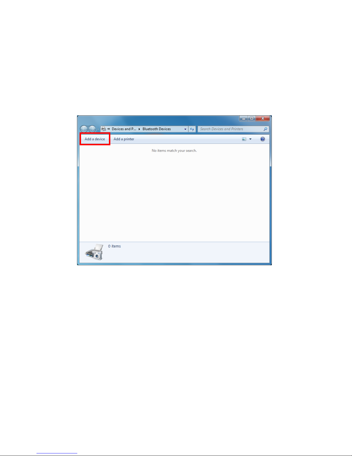
Step 2:
Enter the PC/Notebook’s Bluetooth application, as per Figure 1‐3, and click Add a Device.
Figure 1‐3: PC/NB Bluetooth application Main Window
Page 10
-10-
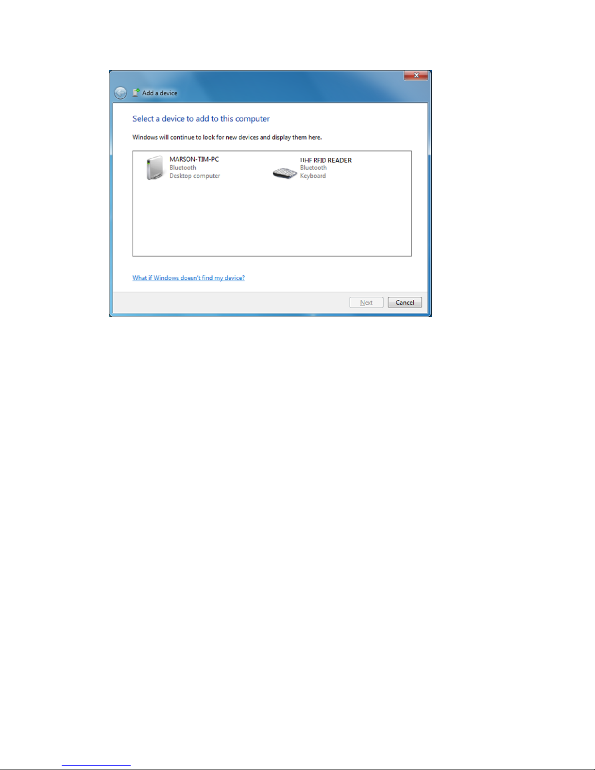
Step 3:
In the Add a device window, double click UHF RFID Reader to connect, as per
Figure 1‐4.
Figure 1‐4: Select Bluetooth Device window
Page 11
-11‐
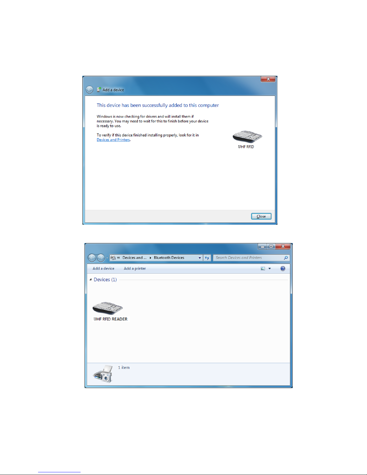
Step 4:
When successfully connected the RP901 will emit two short beeps, and the blue LED
indicator will shut off. The PC/NB will show a message window like in Figure 1‐5, and after
clicking Close the PC/NB Bluetooth application Main Window will show UHF RFID Reader as
a connected device, as per Figure 1‐6.
Figure 1‐5: Connection Successful message window
Figure 1‐6: PC/NB Bluetooth application Main Window
Step 5:
Launch an application program that can accept HID keyboard input, such as Notepad. RFID
Tag data read by the RP901 will output to that application program.
Page 12

-12‐
1‐4‐4. Connecting to an Apple iOS Device
Step 1:
Press and hold the Trigger Buttonfor 2 seconds to boot the unit, afterwhichtheblueLED
indicator will flash continuously. (Ifthe blue LED indicator does not flash, it means RP901 is not
currently in Bluetooth Mode. Please refer to Section 5‐3. Communication Interface,and
change the Communication Interface to BT‐HID.)
Step 2:
On the Apple iOS device, go to Settings > Bluetooth, and turn on Bluetooth, as per Figure 1‐8.
Figure 1‐8: Bluetooth Settings screen
Page 13

-13‐
Step 3:
In the discoverable devices list, select UHF RFID Reader, as per Figure 1‐9
Figure 1‐9: Select UHF RFID Readerfrom the discoverable device list.
Step 4:
Upon establishing connection the RP901 will emit two short beeps and turn o
f
f
its blue LED
indicator. Also, the UHF RFID Reader in the Apple iOS device’s Bluetooth devices list will list as
“Connected”, as per Figure 1‐10.
Figure 1‐10: The UHF RFID Reader now lists as “Connected”
in the discoverable devices list.
Page 14

-14‐
Step 5:
Launch an app that can accept HID keyboard input, such as Notes. RFID Tag data read by RP901 will
output to that app, as per Figure 1‐11.
Figure 1‐11: UHF RFID Tag data will output to an app.
Step 6:
Ifa virtual keyboard is required, please press the Function Button once, as per Figure 1‐12. At this
moment the RP901 will emit one short beep, and the Apple iOS device’s virtual keyboard will pop
out.
Trigger Button Function Button
Figure 1‐12: Trigger Button and Function Button
Page 15
-15‐
1‐4‐5. Connecting to an Android Device
Step 1:
Press and hold the Trigger Buttonfor 2 seconds to boot the unit, afterwhichtheblueLED
indicator will flash continuously. (Ifthe blue LED does not flash, it means the unit is not currently
in Bluetooth Mode. Please refer to Section 5‐3. Communication Interface,andchangethe
Communication Interface to BT‐HID.)
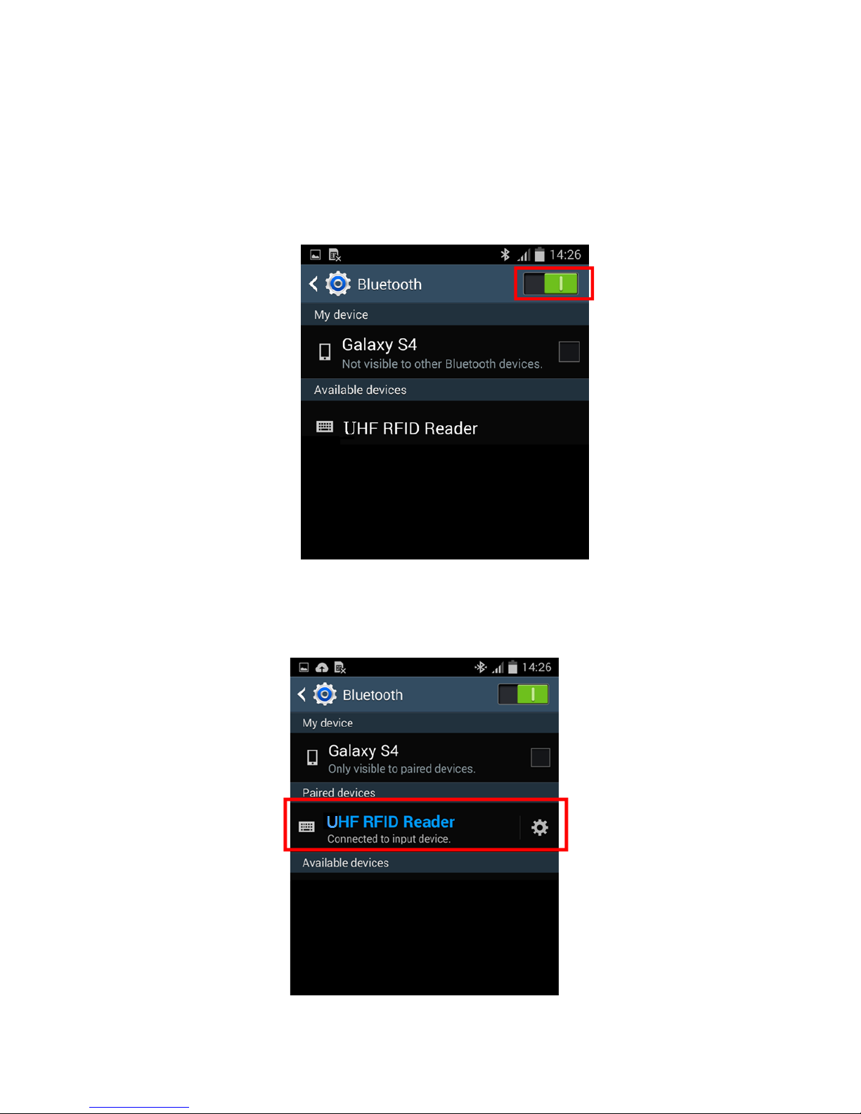
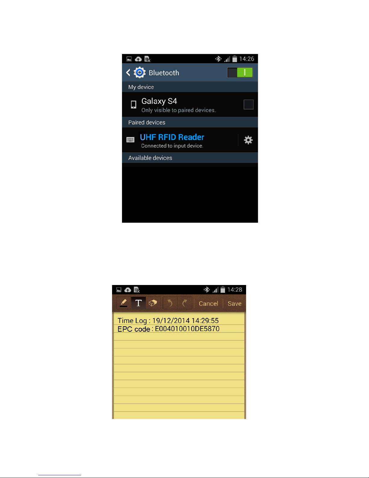
Step 2:
On the Android device, go to Settings > Bluetooth, and turn on Bluetooth, as per Figure 1‐13.
Figure 1‐13: Bluetooth Settings screen
Step 3:
In the available devices list, select UHF RFID Reader, as per Figure 1‐14.
Figure 1‐14: Select UHF RFID Reader from the Bluetooth Settings screen.
Page 16
-16‐
Step 4:
Upon establishing connection the RP901 will emit two short beeps and turn o
f
f
its blue LED indicator.
Also, the UHF RFID Reader in the Android device’s Bluetooth devices list will list as “Connected”, as
per Figure 1‐15.
Figure 1‐15: The UHF RFID Reader now lists as
“Connected” in the Bluetooth setup screen.
Step 5:
Launch an app that can accept HID keyboard input, such as ColorNote. RFID Tag data read by the
RP901 will output to that app, as shown in Figure 1‐16.
Figure 1‐16: RFID Tag data outputs to an app.
Page 17
-17‐
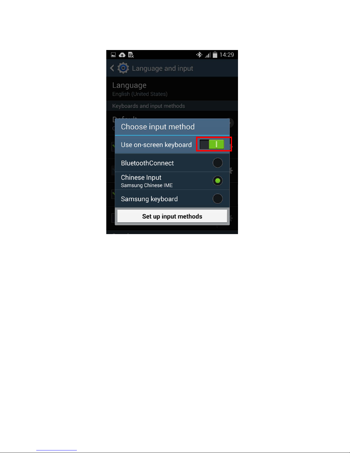
Step 6:
Ifa virtual keyboard is required, please go to Settings > Language and Input > Default,andturn
o
f
f
the physical keyboard (or in some cases, turn on the on‐screen keyboard) in the Select Input
Method screen, as shown in Figure 1‐17. At this time the virtual keyboard will resume normal
operation.
Figure 1‐17: Turn on the on‐screen keyboard.
Page 18
-18‐
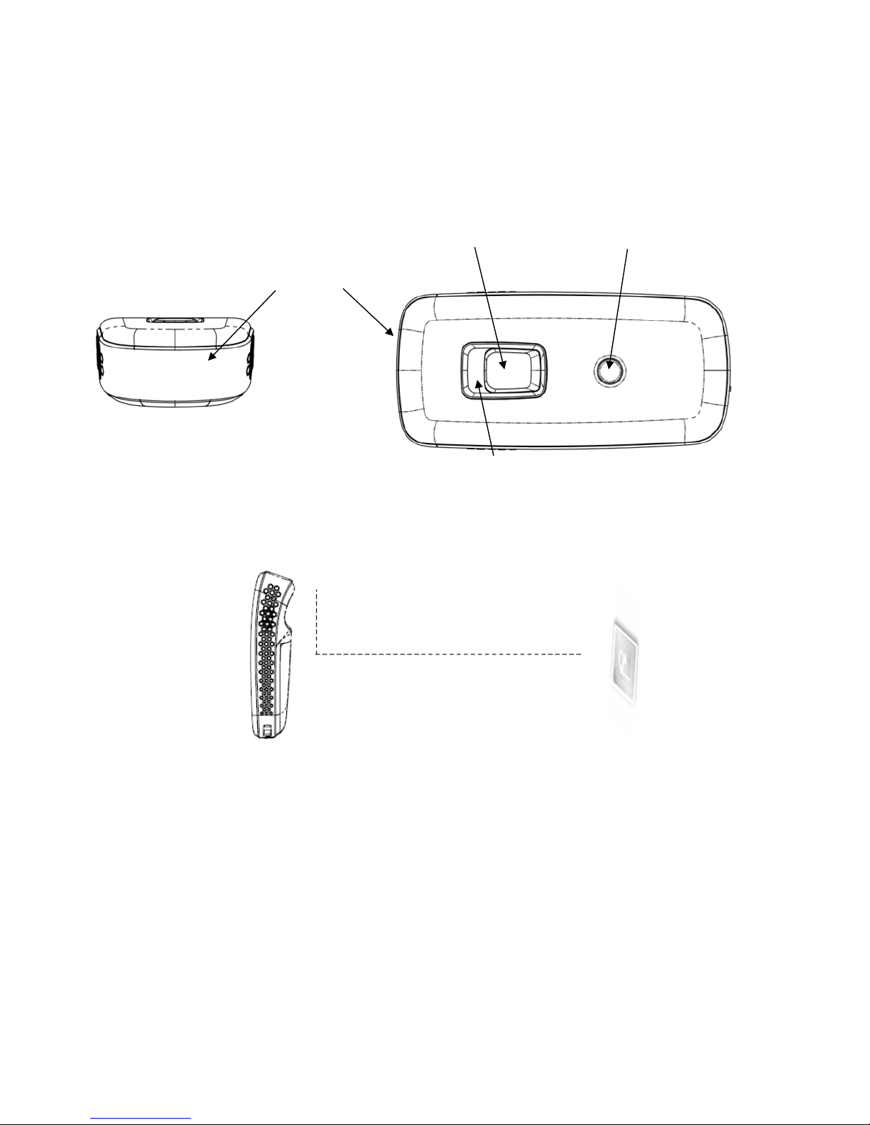
1‐4‐6. Reading RFID T ags
RP901’s RFID antenna is located at itsfront (as per Figure 1‐18). When reading, hold the unit, aim at
the RFID tag (as per Figure 1‐19), and press the Trigger button. Ifreading is successful (Good Read),
the RP901 will emit one beep and the green LED indicator will simultaneously litfor one second.
Reading Distance varies based on RFID tag's specifications and the different placement of tags.
Antenna
Blue/Green/Red LED indicator
Figure 1‐18: Antenna, LED, Trigg er Button and Function Button
Figure 1‐19: Aiming at a RFID Tag and Reading Distance
CAUTION ! Reading distance may be impacted by the type of tag and environmental conditions. Figure 1‐19
is based on Alien 964X Higgs‐3tagandtestedinanofficeenvironment(25˚C).
Trigger Button
Function Button
RFID Tag
Reading Distance (> 100cm)
RP901
(Side View)
90˚
Page 19

-20‐
1‐4‐7. Clearing the Bluetooth Pairing Record
The RP901 will save its Bluetooth pairing records and, when disconnected, will automatically attempt
to restore previous connections. Thefollowing methods will clear RP901’s Bluetooth pairing record,
f
acilitating new connections. After clearing its Bluetooth pairing record the RP901 will break o
f
f
all
Bluetooth connections, entering Bluetooth Disconnected status.
Step 1:
To clear the pairing record from Host, please enter Bluetooth application, and remove/forget the “UHF
RFID reader” in the device list.
Step 2:
To clear the pairing record from RP901, press and hold the RP901’s Function button without releasing
for about 5 seconds and the RP901 will emit 3 short beeps and its Blue LED will start flashing as
confirmation that it has cleared its Bluetooth pairing record.
Blue/Green/Red LED
indicators
Figure 1‐20: Trigger Button and Function Button
CAUTION !
1 . Please make sure both Step 1 & 2 are done as instructed before establishing new connection
with RP901 from the new/old Host. If either of Step 1 or 2 is skipped, your new connection with
RP901 m ight be requested for a pincode, which is unable to be input from RP901 (as it does not
have a numeric keypad). To fix this, redo Step 1 & 2, restart your Host device and try establishing
new connection with RP901 again.
2 . After clearing the Bluetooth connection record the RP901 will enter Bluetooth Disconnected
status and continuously flash its blue LED indicator. If the blue LED indicator does not flash, it
means RP901's Communication Interface is not in Bluetooth Mode. Please refer to Section 5‐3.
Communication Interface.
Trigger Button
Function Button
Page 20

-21‐
1‐4‐8. Ret rieving/Deleting Memory Data
When the Communication Interface is set to Memory (refer to Section 5‐3. Communication Interface),
data obtainedfrom RFID Tag read operations will be stored in RP901’s memory. Thefollowing steps
will store or delete the data within.
A. Retrieving the Data in Memory
Step 1:
After completing an RFID Tag read operation, use a micro USB cable and connect the RP901
to a PC/NB.
Step 2
Open the My Computer window and enter the removable storage device “MiniScan”,
as per Figure 1‐21.
Figure 1‐21: Enteringtheremovablestoragedevice“MiniScan”throughMy Computer.
Page 21

-22‐
Step 3:
Copy the file TAGDATA.TXT,found in the removable storage device “MiniScan”,
to the PC/NB, as per Figure 1‐22.
Figure 1‐22: Copy the file TAGDATA.TXT to the PC/NB.
Step 4:
Skip the following steps ifyou accept memory data stored in *.txt format.
Step 5:
Open TAGDATA.TXT using Excel.
In the Text ImportWizard, Step 1 of3 dialogue box, choose Delimited,andclickNe
x
t
,as
per Figure 1‐23.
Figure 1‐23: TextImport Wizard, Step 1 of 3 dialogue box.
Page 22

-23‐
Step 6:
In the Text Import Wizard ‐ Step 2 of 3 dialogue box, select Comma, and click Next,as
per Figure 1‐24.
Figure 1‐24: Text Import Wizard ‐ Step 2 of 3 dialogue box
Step 7:
In the TextImport Wizard‐ Step 3 of3dialogue box, ifthere are no special requirements,
directly click Finish,asperFigure1‐25.
Figure 1‐25: Text Import Wizard ‐ Step 3 of 3 dialogue
Page 23

-24‐
Step 8:
The Memory data will appear in theform ofan Excel spreadsheet, as per Figure 1‐26. Ifrequired to
change the dataformat, please refer to sub‐section 5‐4. Memory Communication Interface
Figure 1‐26: Memory data, as shown in an Excel table.
B. Deleting the Data in Memory
To delete the data on RP901’s Memory, please directly delete thefile TAGDATA.TXT in the
removable storage device “MiniScan”, as per Figure 1‐27. In about 5 seconds the RP901 will emit 2
short beeps, indicating a successful delete.
Figure 1‐27: Deleting the file TAGDATA.TXT
Page 24

-25‐
2. Configuration Mode
2‐1. Entering Configuration Mode
Under normal circumstances, the RP901 enters the Normal Operation Mode upon power‐up. The
f
ollowing steps will switch the RP901 to Configuration Mode and connect it to the Host PC’s RFID Utility.
Step 1:
Use a micro USB cable and connect the RP901 to the Host PC.
Step 2:
Press and hold RP901’s Function button first without releasing, then press and hold the Trigger button, as
per Figure 2‐1. After pressing both buttonsfor about 5 seconds, the RP901 will emit two short beeps, turn
on Green LED indicator, and enter Configuration Mode. At the same time it will switch its Communication
Interface to USB Virtual COM.
Figure 2‐1: Press both buttons on the RP901.
Step 3:
Check the Host PC’s Device Manager window to see ifthe USB Virtual COM device has
been detected, as per Figure 2‐2.
Figure 2‐2: Check the Host PC and see whether the USB Virtual COM
device has been detected.
Trigger Button
Function Button
Page 25

-26‐
Step 4:
Open the RFID Utility from the Host PC and complete the connection, as per Figure 3‐1.
The above steps will switch the RP901 to Configuration Mode and connect it to the Host PC’s RFID
Utility. The User may begin setting parameters on the RP901. For details refer to Sections 4. RFID
Parameters Setup and 5. Other Parameters Setup.
2‐2. Canceling / Exiting Configuration Mode
Once the RP901 enters Configuration Mode, ifthere are no communications instructions with the Host PC
within the Wait Time, or ifExit is selected within the RFID Utility, it will automatically exit Configuration
Mode and return to Normal Operation Mode. Please refer to Section 6‐1. System. When the unit exits
Configuration Mode it will emit 2 short beeps and turn o
f
f
the Green LED indicator.
While within Wait Time, pressing RP901’s Function button and then the Trigger button, holding both
buttonsfor about 5 seconds, will also exit Configuration Mode. For full details refer to Section 5‐11. Wait
Time.
CAUTION !
Prior to entering Configuration Mode, the RP901 will record the Communication Interface in use.
Therefore if the Communication Interface was BT‐HID prior to entering Configuration Mode, upon exiting
Configuration Mode the Communication Interface will be restored to BT‐HID; if the Communication Interface
setting gets changed while in Configuration Mode, for example changed to USB‐HID, then upon exiting
Configuration Mode the Communication Interface will become the newly designated one, in this case USB‐
HID. For more details of RP901’s Communication Interface, see Section 5‐3. Communication Interface.
Page 26

-27‐
3. Operating the RFID Utility
Execute RFID Utility and enter the program; choose the COM port to connect with, and click the
“Link” button, as per Figure 3‐1. Once connected, you will enter the Program’s Main Window, as per Figure 3
‐2.
Figure 3‐1: Choosing the COM port to connect
3‐1. Introduction to Main Window
Once connected, enter the Program Operationmainwindow,asshowninFigure3‐2 and explained
below.
(1) The Title Bar (upper‐most area) shows the firmware version ofthe connected RP901.
(2) Additional Functions area:
Communication: Disconnect or change the COM port.
Retrieve: Read RP901’s operation parameters.
Update: Upload pr esently configured operation data, etc.
For full details please refer to Section 6. Additional Functions of RFID Utility
(3) Settings Window: provides System Parameters and Settings.
For full details please refer to 4. RFID Parameters Setup, and 5. Other Parameters Setup
(4) Notifications Window: Shows currently selected parameters and simple explanations.
(5) Status Bar (lower‐most area): shows RP901’s current connection state.
(6) Exit: Exit the Utility program and inform RP901 as to the program termination. The RP901 will
return to Normal Operation Mode.
Page 27

-28‐
(1) Software Version
(2) Additional Functions
(6)Exit
(3)Settings Window
(4) Suggestion
Window
(5) Connection Status
Figure 3‐2: Program Operation Main Window
Page 28

-29‐
4. RFID Parameters Setup
Figure 4‐1 are all options of RFID Parameters Setup displayed in tree view:
Figure 4‐1 RFID Parameters Setup
Choose the item to configure, then double click the le
f
t mouse button or press Enter to enter
the desired parameters setting window.
4‐1. Operation Mode
Figure 4‐2
Configure the Operation Mode for either Trigger Mode or Auto
Mode.
Configuration Method:
Select one of the two options then click to send the new
parameter to the RP901.
Default Setting: Trigger Mode
Page 29

-30‐
Detailed explanations of Trigger Mode and Auto Mode are as following:
(1) Trigger Mode Operation Method:
<A> Press the Trigger button to start a tag Scan operation. Upon successful tag scan (Good Read)
the scan operation will stop.
<B> In Single‐Tag Read mode, ifthe Trigger button is pressed but no successful tag scan
occurred within the Scan Period, the scan operation will terminate. In any case, releasing
the Trigger button will terminate the scan operation.
<C> In Multi‐Tag Read mode, Ifthe Trigger button is pressed but the number of tags read is
smallerthan Tag‐Lis t Counter within the Scan Period, the scan operation will be paused.
Pressing the Trigger button again will continuethescanoperation. Inanycase,releasing
the Trigger button will pause the scan operation.
<D> In Sleep Mode, pressing the Trigger button will automatically reactivate Trigger Mode. For
Sleep Mode settings, please see 5‐8. Sleep Mode / Timer.
(2) Auto Mode Operation Method:
<A> The Auto Mode follows the same rules of operation as the Trigger Mode, except that scan
operation start automatically , without pressing the Trigger button.
<B> Scan operation is repeated and do not terminate unless the RP901 enters Sleep Mode.
<C> In Sleep Mode, Pressing the Trigger button will automatically reactivate Auto Mode.
CAUTION ! Auto Mode is mo re power‐consuming.
4‐2. Read Mode
RP901 supports Single‐Tag Read mode or Multi‐Tag Read mode. Different Memory Bank can be read
according to Read mode selected. Session and Target can be set for determining how often a tag will
respond to a query from the reader.
4‐2‐1. Single‐Tag Read or Multi‐Tag Read
Configure the Read Mode
f
or either Single‐Tag Read mode or Multi‐Tag Read mode.
Figure 4‐3
Configuration Method:
Select one of the two options then click to send the new
parameter to the RP901.
Default Setting: SingleTag
Detailed explanations of Read Tag Modes are as following:
(1) Single‐Tag Read Mode:
In Single‐Tag Read mode, only one tag will be read within the Scan Period.
Page 30

-31‐
(2) Multiple‐Tag Read Mode:
In Multiple‐Tag Read mode, multiple tags will be read, with each tag being read once, within the
Scan Period.
4‐2‐2. Sessions and Target:
Session and Target can be set for determining how often a tag will respond to a query from the
reader and allowing for multiple readers to conduct independent inventories.
4‐2‐2‐1. Session
There are four Sessions, S0, S1, S2 and S3 can be selected.
Configuration Method: Select one of the Sessions, then click to
send the new parameter to t he RP901.
Default Setting: S0
4‐2‐2‐2. Target
There are two Targets: Single Target and Dual Target. RP901 will read flag A if Single Target is
selected, and will read A first then read B if Dual Target is selected.
Configuration Method: Select one of the Targets, then click to
send the new parameter to t he RP901.
Default Setting: Single Target
4‐2‐3. Tag Info ‐ Memory Banks in Single‐Tag Read mode:
In Single‐Tag Read mode, Both EPC Code and TIDdataoftag'sMemoryBankcanberead.USER
Memory of tag's Memory Bank can also be read.
Memory Bank in Single‐Tag Read:
Configuration Method: Multiple Memory Bank can be selected, once
confirmed then click to send the new parameter to the RP901.
Default Setting: EPC Code and TID
Figure 4‐6
Figure 4‐4
Figure 4‐5
Page 31

-32‐
4‐2‐4. CRC Value
In Single‐Tag Read mode and only EPC Code of tag's Memory Bank to be read, CRC Value can be
Enabled.
Configuration Method:
Select Enable or Disable, then click to s send the new
parameter to the RP901.
Default Setting: Disable
(2) Multi‐Tag Read mode:
In Multi‐Tag Read mode, Multiple tags will be read simultaneously and the Tag‐List Counter will
decide how many tags can be read within the Scan Period. The same tag data will be only
outputted once within one Scan Period.
4‐2‐5. User Memory ‐ Memory Bank in Single‐Tag Read mode:
In Single‐Tag Read mode, Access Password, Starting Pointer and Data Length must be set when
User Memory is selected.
4‐2‐5‐1. Access Password
Up to 8 digits of hexadecimal value can be entered if A ccess Password is required.
ConfigurationMethod: set Access Password, once confirmed then click
to send the new parameter to the RP901.
Default Setting: None
4‐2‐5‐2. Starting Pointer and Data Length
ConfigurationMethod: set Starting Pointer and Data Length , once
confirmed then click to send the new parameter to the RP901.
Default Setting:
The maximum Data Length is 512 words when Starting Pointer is set to 0.
Starting Pointer: 0~511,default: 0
Data Length (words): 1~512, default: 1
CAUTION ! 1. Only the Block 0 of File 0 of User Memory is supported.
2. Invalid parameters of USER Memory may cause an Error‐Message. See section 4‐6‐10
Error‐Message.
Figure 4‐7
Figure 4‐9
Figure 4‐8
Page 32

-33‐
4‐2‐6. Tag Info ‐ Memory Bank in Multi‐Tag Read mode:
In Multi‐Tag Read mode, either EPC Code or TID data of tag's Memory Bank can be read.
Memory Bank in Multi‐Tag Read:
Configuration Method: Select one of the Memory Banks, then click
to send the new parameter to the RP901.
Default Setting: EPC Code
4‐2‐7. Tag‐List Counter
In Multi‐Tag Read mode, the Tag‐List Counter will decide how many tags can be read within the
Scan Period.
Configuration Method:
Select one of the numbers (1~ 128), then click to s send the
new parameter to the RP901.
Default Setting: 64
CAUTION ! The result of Multi‐Tag Read mode operation will vary because of the different
placementoftagsaswellasthetypeoftags.
4‐3. Scan Period and Delay Time
Sets the Scan Period and the Delay Time between tags scan.
4‐3‐1. Scan P eri od
In Trigger Mode, if the Trigger button is pressed and no successful
tag scan is completed within the Scan Period, the scan operation
terminates. This feature may be disabled by setting Scan Period to
0(Disabled).
Configuration Method: Select a value (0~255 seconds) then click
to send the new parameter value to the RP901.
Default Setting: Disable
Figure 4‐10
Figure 4‐11
Figure 4‐12
Page 33

-34‐
4‐3‐2. Delay Time
Sets the Delay Time between every tag scan. This feature may be
disabled by setting Delay Time to 0 (Disabled).
Configuration Method:
Select a value (0 ~ 1500ms) then click to transfer the
new parameter value to the RP901.
Default Setting: Disable
Figure 4‐13
Page 34

‐35‐
4‐4. Scheme and Filter
Scheme and Filter is effective only when EPC Code of Tag Info is selected.
4‐4‐1. EPC Scheme
Thisfunction wi
ll
def
ine whic
h
kindoftag
scanbereadaccordingto theEPCScheme oftags.
Configuration Method: Multiple types of EPC Scheme can be selected. Once confirmed, click
to send the new parameter values to the RP901.
Default Setting:AllSchemes are selected.
4‐4‐2. Accepted Filter
Accepted Filter defines a pattern or a range (2 patterns) of EPC Code. A Tag can be accepted
if the selected part of its EPC Code is equal to Pattern 1 or Pattern 1≦the selected part of its
EPC code≦Pattern 2.
Configuration Method: Enable or Disable Included
Filter. Input the Start Bit of EPC Code by 4 bits
(0,4,8...) and the pattern string of Accepted Filter
in hexadecimal then click to send the new
parameter values to the RP901.
Default Setting: Disable
Start Bit of EPC Code: 0
Pattern 1 :””
Pattern 2 :””
Status:
Enable or Disable the Accepted Filter function. Pattern 1 must be defined if Enable is selected
while two patterns (Pattern 1 and Pattern 2) must be defined if Enable‐Range is selected.
Start Bit of EPC Code:
The start point (by 4 bits, from 0,4,8... to 248) of EPC Code to be compared.
Pattern 1 or Pattern 2:
the pattern string of Accepted Filter in hexadecimal. The length of Pattern 1 and Pattern 2
must be same and equal to the length of those numbers of EPC code to be compared.
Figure 4‐14
Figure 4‐15
Page 35

‐36‐
4‐4‐3. Rejected Filter
Rejected Filter defines a pattern or a range (2 patterns) of EPC Code. A Tag can be Rejected if
the selected part of its EPC Code is equal to Pattern 1 or Pattern 1≦the selected part of its
EPC code≦Pattern 2.
Configuration Method: Enable or Disable Rejected
Filter. Input the Start Bit of EPC Code by 4 bits
(0,4,8...) and the pattern string of Rejected Filter in
hexadecimal then click to send the new
parameter values to the RP901.
Default Setting: Disable
Start Bit of EPC Code: 0
Pattern 1 :””
Pattern 2 :””
Status:
Enable or Disable the Rejected Filter function. Pattern 1 must be defined if Enable is selected
while two patterns (Pattern 1 and Pattern 2) must be defined if Enable‐Range is selected.
Start Bit of EPC Code:
The start point (by 4 bits, from 0,4,8... to 248) of EPC Code to be compared.
Pattern 1 or Pattern 2:
the pattern string of Rejected Filter in hexadecimal. The length of Pattern 1 and Pattern 2
must be same and equal to the length of those numbers of EPC code to be compared.
Note:
TheAcceptedFilter wi
ll
bep
rocesse
d
f
irst whenbothAcceptedFilter andRejectedFilter are enabledat
thesametime.
4‐4‐4. Affected Scheme of Filters
This function will define which kind of tags can will be affected by Accepted Filter and
Rejected Filter according to the EPC Scheme of tags.
Configuration Method: Select one EPC Scheme then click to send the new
parameter value to the RP901.
Default Setting: SGTIN‐96
Figure 4‐17
Figure 4‐16
Page 36

‐37‐
4‐5. RF Parameters
4‐5‐1. RF Out put Power
Thisfunction willset theRFoutputpower ofRP901. Lower outputpower willresultinshorter
readin
g
d
istance as wellas morepower saving.
Configuration Method: Select one RF output
power level then click to send the new
parameter value to the RP901.
Default Setting: High
Figure 4‐18
Page 37

‐38‐
4‐6. Data Output Format
Figure 4‐19: Setting the Data Output Format
The Data Output Format options include settings for Time Log, RSSI, EPC Scheme, EPC
Code, PC (Protocol Control), CRC (Cyclic Redundancy Check) and TID data.
Each parameter of data output can be set like in Figure 4‐16: simply choose one of either
Disable
or Enable
then click to send the new parameter values to the RP901.
There are two output formats available, one Full Description another Simple Cascade. In Simple
Cascade format, the caption is neglected even it is enabled. For example:
Full Description Format:
Time Log: 2014/12/19 12:30:59
RSSI:3A
EPC Scheme:STGIN‐96
EPC Code:301122334455667788990011
PC: 3000
CRC: ABCD
TID: 123456789012
Simple Cascade Format: (TID is disabled in this example)
2014/12/19 12:30:59,3A,STGIN‐96,301122334455667788990011,3000,ABCD
Page 38

‐39‐
4‐6‐1. Output Format
Select the Simple Cascade format or Full Description format.
Configuration Method: Choose one of the two formats
then click to send the new parameter values to
the RP901.
Default Setting: Simple Cascade Format
4‐6‐2. Time Log
Whether to output the Time Logfor tag scanned. For date and timeformats please refer to 5‐1. Date
Format and 5‐2. Time Format.
Configuration Method: Choose Disable or Enable.
Default Setting: Disable
If Output T ime Log is enabled, the following may also be configured:
4‐6‐2‐1. Output Time Log’s caption “Time Log:”
Configuration Method: Choose Disable or Enable.
Default Setting: Disable
Figure 4‐20
Figure 4‐21
Figure 4‐22
Page 39

‐40‐
4‐6‐3. RSSI (Received Signal Strength Indicator)
Whether to output tag's RSSI value.
Configuration Method: Choose Disable or Enable.
Default Setting: Disable
If Output RSSI is enabled, the following may also be configured:
4‐6‐3‐1. Output RSSI 's caption “RSSI: ”
Configuration Method: Choose Disable or Enable.
Default Setting: Disable
4‐6‐4. EPC Scheme
Whether to output EPC Scheme. This function is available when the EPC Code ofTag
Info is selected. Please see 4‐2‐2and4‐2‐5TagInfo.
Configuration Method: Choose Disable or Enable.
Default Setting: Disable
IfOutput EPC Scheme is enabled, thefollowing may also be configured:
Figure 4‐23
Figure 4‐24
Figure 4‐25
Page 40

‐41‐
4‐6‐4‐1. Output EPC Scheme caption “EPC Scheme:”
Configuration Method: Choose Disable or Enable.
Default Setting: Disable
4‐6‐5. EPC Code
Whether to output EPC Code. This function is available when the EPC Code ofTag Info
is selected. Please see 4‐2‐2and4‐2‐5Tag Info.
Configuration Method: Choose Disable or Enable.
Default Setting: Enable
If Output EPC Code is enabled, the following may also be configured:
4‐6‐5‐1. Output EPC Code’s caption “EPC Code:”
Configuration Method: Choose Disable or Enable.
Default Setting: Disable
Figure 4‐26
Figure 4‐27
Figure 4‐28
Page 41

‐42‐
4‐6‐6. PC (Protocol Control)
Whether to output tags’ PC data. This function is available when the EPC Code ofTag
Info is selected. Please see 4‐2‐2and4‐2‐5TagInfo.
Configuration Method: Choose Disable or Enable.
Default Setting: Disable
If Output PC data is enabled, the following may also be configured:
4‐6‐6‐1. Output PC data's caption “PC:”
Configuration Method: Choose Disable or Enable.
Default Setting: Disable
4‐6‐7. CRC (Cyclic Redundancy Check)
Whether to output tags’ CRC value. This function is available when the EPC Code o
f
Tag Info is selected. Please see 4‐2‐4CRCValue.
Configuration Method: Choose Disable or Enable.
Default Setting: Disable
If Output CRC value is enabled, the following may also be configured:
Figure 4‐29
Figure 4‐30
Figure 4‐31
Page 42

‐43‐
4‐6‐7‐1. Output CRC value's caption “CRC:”
Configuration Method: Choose Disable or Enable.
Default Setting: Disable
4‐6‐8. TID data
Whether to output tag's TID data. This function is available when the TID data ofTag
Info is selected. Please see 4‐2‐2and4‐2‐5TagInfo.
Configuration Method: Choose Disable or Enable.
Default Setting: Disable
If output TID data is enabled, the following may also be configured:
4‐6‐8‐1. Output TID data's caption “TID:”
Configuration Method: Choose Disable or Enable.
Default Setting: Disable
Figure 4‐33
Figure 4‐34
Figure 4‐32
Page 43

‐44‐
4‐6‐9. User Memory
Whether to output tag's Usermemory. This function is available when the Usermemor
y
ofTag Info is selected. Please see 4‐2‐2TagInfo.
Configuration Method: Choose Disable or Enable.
Default Setting: Disable
If output User memory is enabled, the following may also be configured:
4‐6‐9‐1. Output User Memory 's caption “USER memory:”
Configuration Method: Choose Disable or Enable.
Default Setting: Disable
4‐6‐10. Error‐Message
Whether to output Error‐Message. Error‐Message displays when there is an error encountered
during a scan operation. An Error‐Message will be followed by an Error‐Code.
For Example:
Error‐Message: 0A
Error‐Message is applicable only for Trigger Mode and Single‐Tag Read Mode. Please see 4‐1
Operation Mode and 4‐2 Read Mode.
Configuration Method:Choose DisableorEnable.
Default Setting: Disable
Figure 4‐35
Figure 4‐36
Figure 4‐37
Page 44

‐45‐
4‐6‐11. No‐Tag‐Message
Whether to output No‐Tag‐Message. No‐Tag‐Message is a preset message such as “No Tag” that
displays when no Tag could be read successfully upon terminating a scan operation.
No‐Tag‐Message is applicable only for Trigger Mode and Single‐Tag Read Mode. Please see 4‐1
Operation Mode and 4‐2 Read Mode.
Configuration Method: Choose Disable or Enable.
Default Setting: Disable
Figure 4‐38
Page 45

‐46‐
5. Other Parameters Setup
RP901 has other parameters not related to RFID, such as Date Format, Time Format, Communication
Interface, Sleep Mode etc., as per Figure 5‐1.
Figure 5‐1: Other parameters not related to RFID.
5‐1. Date Format
Figure 5‐2
Date format of memory data’s date mark.
Set how date
f
ormat is arranged: D means Date, M means Month,
Y means Year. 16 choices are available.
Configuration Method:
Choose one among the 16 then click
to transfer the
parameter setting to the RP901.
Default Setting: DD/MM/YYYY
Page 46

‐47‐
5‐2. Time Format
Figure 5‐3
Time format ofmemory data’s time mark.
Set how timeformat is arranged: H means Hour, M means
Minute, S means Second. 2 choices are available.
Configuration Method:
Choose one ofthe two then click to transfer the
parameter value to the RP901.
Default Setting: HH:MM:SS
Page 47

‐48‐
5‐3. Communication Interface
Set the communication interface between the RP901 and the Host
PC, meaning the communication interface for RP901’s data output.
Five choices are available.
Configuration Method:
Choose one of the five then click to transfer
parameter values to the RP901.
Default Setting: BT‐HID
Each Communication Interface is described in det ails as below:
(1) USB‐VCP
Use USB V irtual COM as communication interface.
(2) USB‐HID
Use USB HID Keyboard as communication interface.
(3) Memory
When using Memory as the communication interface, the RP901 will not output data scanned, will
store them within its internal memory as a file (about 2MB in size). To access that file, a connection
with the Host PC is required.
(4) BT‐HID
Use Bluetooth HID Keyboard as communication interface.
(5) BT‐SPP
Use the Bluetooth SPP (BT Virtual COM) as communication inter
f
ace.
NOTE:
No matter what interface is selected, Tag data will be sent in ASCII format. For example, tag data
<0x03> is sent to the host as <0x30><0x33>, 2 bytes in total.
Figure 5‐4
Page 48

‐49‐
5‐4. Memory Communication Interface Options
When the Memory Communication Interfaceischosen,eachscanneddataismarkedwithdateandtime,
and then stored in the internal memory. When the memory is full with data, Tag reading will elicit a warning
signal in theform of3 short beeps and a one second lighting ofthe red LED indicator, and no scanning will
actually occur. Only when the data inside t he memory has been received and deleted by the Host PC may
the scan operation resume. Choosing Memory as the Communication Interface enables the Field Separator
and Storage Sequence configuration options.
5‐4‐1. Field Separator
Figure 5‐5
Set the symbol used to separate each field ofdataformatting.
Configuration Method:
Directly input the symbol, maximum 1 Byte in size then click
to transfer the parameter value to the RP901.
Default Setting: Comma (,)
5‐5. BT‐HID and BT‐SPP Communication Interface Options
When BT‐HID or BT‐SPP is chosen as the Communication Interface, the BT‐ID and BT‐Pin‐Code options
become available.
5‐5‐1. BT ‐ID
Figure 5‐7
5‐5‐2. BT‐Pin‐Code
Figure 5‐8
Set the Bluetooth‐ID name, for Host‐PC display purposes.
Configuration Method:
Choose a desired phrase, maximum 16 Bytes. Once chosen, click
to transfer the parameter value to the RP901.
Default Setting: UHF RFID Reader
Set the Pin‐Code used when connecting to the Host‐PC via
BT‐SPP.
Configuration Method:
Enter the Pin‐Code value, maximum 8 Bytes. Once chosen,
click
to transfer the parameter value to the RP901.
Default Setting: 1234
Page 49

‐50‐
5‐6. USB‐HID and BT‐HID Communication Interface Options
When USB‐HID orBT‐HID are chosen as the Communication Interface, additional options become
available. These include Key Layout, Key Numeric, Key Caps lock, Inter‐block, and Inter‐character.
5‐6‐1. Keyboard La yout
Figure 5‐9
Set the language usedfor RP901’s data output to the Host‐ PC.
24 choices are available.
Configuration Method:
Choose one of24, then click to transfer the parameter
setting to the RP901.
Default Setting: (qwerty) USA
Page 50

‐51‐
5‐6‐2. Key Numeric
Figure 5‐10
Set the keyboard used for RP901’s Scan Code output.
Configuration Method:
Choose one, then click to transfer the parameter setting to
the RP901.
Default Setting: Alpha Numeric
5‐6‐3. Key Caps Lock
Figure 5‐11
Set the keyboard's Caps Lock state to On, Off or Auto.
Configuration Method:
Choose one, then click to transfer the parameter setting to
the RP901.
Default Setting: Lock Off
5‐6‐4. Inter‐block Interval Time
Figure 5‐12
Sets the Interval Time between each packet ofdata (including
the separator symbol) and the next.
Configuration Method:
Choose one (value range 0 ~ 500 ms), then click to transfer
the parametersetting to the RP901.
Default Setting: 0 ms
5‐6‐5. Inter‐character Interval T ime
Figure 5‐13
Set the Interval Time between one character and the next within
each packet ofdata.
Configuration Method:
Choose one, then click to transfer the parameter value to
the RP901.
Default Setting: 0 ms
Page 51
‐52‐
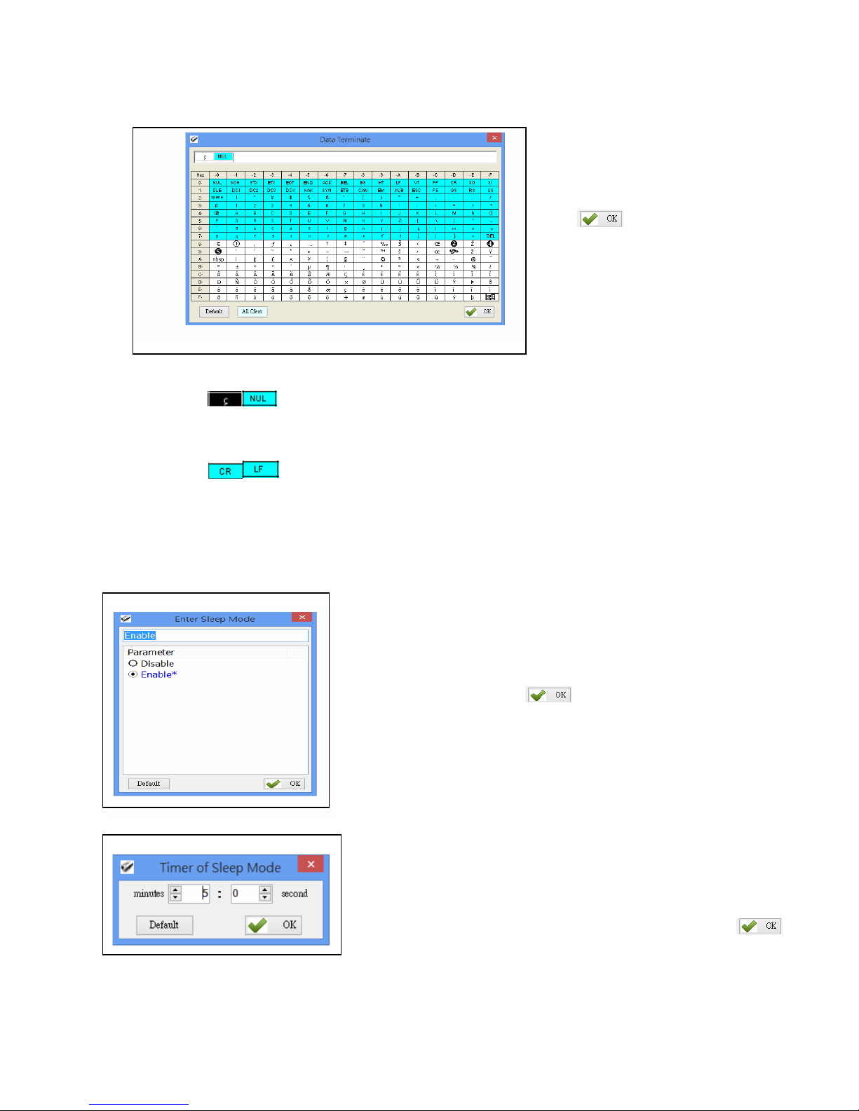
5‐7. Data Terminator
Set the terminator symbol used when uploading RP901’s data to the Host‐PC. It can be 1 or 2 Bytes
depending on the Communication Interface.
Configuration Method:
Choose or type in a symbol using the
special keyboard shown in Figure
4.14. Show 1 or 2 Bytes. Then
click to transfer the parameter
value to RP901.
Figure 5‐14
(1) Data Terminator of USB‐HID / BT‐HID interface:
Default: (<0xE7><0x00>). Totals 2 Bytes.
(2) Data Terminator of USB‐VCP / BT‐SPP interface:
Default: (<0x0D><0x0A>). Totals 2 Bytes.
5‐8. Sleep Mode / Timer
Set the activation statusfor Sleep Mode and the Timer value usedfor entering Sleep Mode. The RP901 will
enter Sleep Mode to conserve power ifthere is no successful Tag scanned after a period oftime.
Figure 5‐15
Figure 5‐16
5‐8‐1. Enter Sleep Mode
Set whether to activate Sleep Mode.
Configuration Method:
Choose one, then click
to transfer the parameter setting
to the RP901.
Default Setting: Enable (activate)
5‐8‐2. Timer of Sleep Mode
Set the waiting time for entering Sleep Mode.
Configuration Method:
Choose a value (range 00:10 ~ 60:00 mm:ss), then click
to transfer the parameter value to the RP901.
Default Setting: 05:00
Page 52

‐53‐
5‐9. Buzzer
Beep tones serve as an indication ofoperation status. For Example, one short beep signifies a Good
Read within a Scan Period and 3 short beeps warn an error.
5‐9‐1. Beep Tone
Figure 5‐17
Set the beep volume or disables beeping.
Configuration Method:
Choose one, then click to transfer the parameter setting to
the RP901.
Defaul t Setting: Medium
5‐9‐2. Beep Time
Figure 5‐18
Set the beep lengthfor the short beep used to signify a Good
Read.
Configuration Method:
Choose a value between 50 ~ 500 ms, using 10 ms intervals.
Then click to transfer the parameter value to the RP901.
Default Setting: 150 ms
5‐10. Vibrator
Enable or Disable the Vibrator which may be used to signify a Good Read during a Scan Period.
Figure 5‐19
Configuration Method:
Choose one ofthe options, then clic
k
to transfer the
parameter setting to the RP901.
Default Setting: Disable (deactivated)
*Note: The duration of vibration is fixed at 200 ms.
Page 53

‐54‐
5‐11. Wait Time
Set the Wait Time used prior to automatically exiting RP901’s Configuration Mode.
When the RP901 is in Configuration Mode, ifthere are no
Figure 5‐20
communication instructions between it and the Host PC within a
Wait Time, it will automatically exit Configuration Mode and
return to Normal Operation Mode. Or, while within Wait Time, i
f
the RP901’s Function button is pressed,followed by the Trigger
button, and both buttons are heldfor about 5 seconds, it will also
exit Configuration Mode.
Configuration Method:
Select a value between 1 ~ 60 minutes, using 1 minute intervals.
Then click to transfertheparametervaluetotheRP901.
Default Setting: 5 minutes
5‐12. System Time
Set the RP901’s System Time
Date format: Year (4 digits), Month (2 digits), Date (2 digits). e.g. Date: 2014/12/19
Time format: Hour (2 digits), Minute (2 digits), Second (2 digits). e.g. T ime: 09:50:30
Figure 5‐21
Configuration Method:
Input the Year, Month, Day, Hour, Minute, Second
within their respective value ranges. Then click to
transfer the parameter values to the RP901.
Default Setting: Synchronized as Host‐PC’s System Time
CAUTION ! Removal of battery or full drain of battery may cause the reader’s System Time to
desynchronize.
Page 54

‐55‐
,
6. Additional Functions
Figure 6‐1: RFID Utility’s Additional Functions
RFID Utility’s additional functions include System, OperationandTools,describedasbelow:
6‐1. System
<A> Communication: When connected, you may click “Stop” to get disconnected then change
COM port and initiate another connection.
Figure 6‐2
CAUTION ! When terminating a connection, the system will force RP901 to terminate the
configuration process.
Page 55

‐56‐
<B> Workplace: Functions such as Reset to Default Window, W indow Size, Fonts …etc, are
configurable in the Workplace Window.
Figure 6‐3
In the lower part of selection window, choose the item you wish to adjust, then double click on it
with your mouse or press the ENTER key to start adjusting.
(1) Default Workplace: Restores all defaults, including window size,font style,font size, etc.
(2) Usualness Font: Mostly usedfor adjustingfontsfor the Main Menu. The user determines its use.
(3) Window‐Width, Height: Adjusts window size onlyfor the Main Window.
<C> Exit: When exiting the RFID Utility, the system will ask whether to terminate all configuration
operation.
Figure 6‐4
CAUTION ! When exiting from the RFID Utility is confirmed, the system will instruct the
RP901 to terminate the configuration process.
Page 56

‐57‐
6‐2. Operation
<A> Retrieve: Read parameter values from the connected RP901.
Update: Upload the current parameter values.
Only when connected to an RP901 may Retrieve and Update be used.
<B> Reset: Restore all parameters to their Default settings.
When the RP901 is connected to the Host‐PC, User can restore all parameters inside the RP901
to their factory Default settings (Reset Reader’ s Parameter to Default).
Figure 6‐5
CAUTION ! Reader’s Communication Interface and the Memory Data saved in TAGDATA.txt will
not be affected by Reset. To configure Communication Interface, please follow instruction of
Setion 5‐3. Communication Interface; to remove Memory Data, please refer to Setion 1‐4‐8.
Retrieving/Deleting Memory Data.
Page 57

‐58‐
6‐3. Tools
<A> Language: Set the display language.
<B> : Update the firmware on RP901.
Please refer to 7. Updating Firmware on RP901.
Page 58

‐59‐
7. Updating Firmware on RP901
7‐1. Entering Firmware Update Mode
Under normal circumstances, the RP901 boots into the Normal Operation Mode. Thefollowing steps will
move the RP901 to Firmware Update Mode and connect it to the Host PC’s RFID Utility tofacilitate
firmware upgrade through USB Virtual COM communication. Steps are asfollowing:
Step1:
Make sure that the RP901 is disconnected from the Host PC.
Connect the RP901 to the Host PC using the Micro USB Cable.
Step 2:
Press the Function button and the Trigger button on the RP901, as per Figure 7‐1. Hold both buttons,
do not release, and use a pin or a straightened paperclip to press the Reset button on the bottom, as per
Figure 7‐2. The RP901 will enter the Firmware Update Mode.
Figure 7‐1: Press both buttons on the RP901 simultaneously.
Reset Button
Figure 7‐2: Press the Reset button
Step 3:
Still holding down the Function button and Trigger button, check the Device Manager on the Host PC to
see ifa USB Virtual COM has appeared, as per Figure 7‐3. Now release the Function button and the
Trigger button. The RP901 will automatically change its Communication Interface to USB V irtual COM.
Trigger Button
Function Button
Page 59

‐60‐
Figure 7‐3: Check the Host‐PC to see if it has detected the USB V irtual COM.
7‐2. Executing Firmware Update
Step 1:
Execute the program. Do not
establish a connection.
Press to cancel the connection process
and enter the program, as per Figure 7‐4.
Cancel
Connection
Figure 7‐4
Step 2:
Choose
and execute
Please refer to 6‐3. Tools
Step 3:
Choose the COM port, as per
Figure 7‐5.
1.
Choose COM port
2. Load bin file
Figure 7‐5
3. Execute Update
Page 60

‐61‐
Step 4:
Load thebinfile,asperFigures7‐5and7‐6.
Figure 7‐6
Step 5:
Click to execute firmware upgrade, as per Figure
7‐5. The system will ask whether to confirm execution.
Figure 7‐7
CAUTION ! While the RP901 is updating its firmware (Figure 7 ‐8), please avoid unnecessary
errors and do not unplug the cable. Incomplete firmware update may cause damage to RP901.
Figure 7‐8
Step 6:
When update is complete, click “OK”to finish the update program, as per Figure 7‐9. The RP901 will reboot and
return to Normal Operation Mode automatically.
Figure 7‐9
 Loading...