

Page 1
Page 2

Page 3

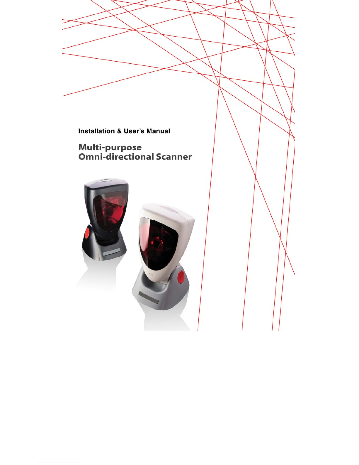
Installation & User’s Manual
Multi-purpose. Omni-directional scanner.
Page 4

Copyright © 2010.
This manual is copyrighted, with all rights reserved. Under the copyright laws, this manual may not, in
whole or in part, be copied, photocopied, reproduced, translated or converted to any electronic medium or
machine readable form without prior written consent of the manufacturer.
Limited Warranty
Under all circumstances this manual should be read attentively, before installing and/or using the product.
In no event shall the manufacturer be liable for any direct, indirect, special, consequential or incidental
damages arising out of the use or inability to use this documentation or product, even if advised of the
possibility of such damages. In particular, the manufacturer shall not be liable for any hardware, software,
or data that is stored or used with the product, including the cost of repairing, replacing or recovering the
above. The manufacturer reserves the right to change parts of the device at any time without preceding or
direct announcement to the client.
The manufacturer reserves the right to revise this manual, and to make changes in the contents without
obligation to notify any person or entity of the revision or change. A serial number appears on the product.
Make sure that this official registration number has not been removed. It should be used whenever
servicing by the manufacturer or an authorized dealer is necessary.
Important
This equipment has been tested and found to comply with the limits for a Class B digital device, pursuant
to EN55022, and with the limits for a class A digital device, pursuant to part 15 of the FCC rules. These
limits are designed to provide reasonable protection against harmful interference when the equipment is
operated in a commercial environment. This equipment generates, uses, and can radiate radio frequency
energy and, if not installed and used in accordance with the user’s manual, may cause harmful
interference to radio communications. Operation of the equipment in a residential area is likely to cause
harmful interference in which case the user will be required to correct the interference at his own expense.
Any unauthorized changes or modifications to this equipment could void the user’s authority to operate
this equipment.
For CE-countries:
– PS705 is in conformity with the CE standards. Please note that a CE-marked power supply unit
should be used to conform to these standards.
Page 5

iii
Table of contents
Preface .................................................................................... 1
Chapter 1 Product Safety ............................................................. 3
1.1 LASER SAFETY ............................................................................... 4
1.2 DECLARATION OF CONFORMITY ................................................. 5
Chapter 2 Installation .................................................................. 7
2.1 UNPACKING ..................................................................................... 8
2.2 CONNECTING ................................................................................ 10
2.3 ADJUSTING .................................................................................... 11
2.4 POWERING ..................................................................................... 12
2.5 INITIALIZING .................................................................................. 13
Chapter 3 Using PS705 .............................................................. 15
3.1 SCANNING BARCODES ................................................................ 16
3.2 CONTROLLING .............................................................................. 17
3.3 MAINTAINING ................................................................................. 17
Chapter 4 Applications .............................................................. 19
Appendices ............................................................................ 21
A. CONNECTOR TYPES AND PIN DEFINITIONS ............................. 22
B. TECHNICAL SPECIFICATIONS .................................................... 23
C. TROUBLESHOOTING .................................................................... 25
Page 6

Page 7

1
Preface
PS705 is a high performance, multi-interface, and omni-directional scanner.
The unit comes with powerful reading sensitivity which allows hands-free bar
code scanning. Bar code labels are read by presenting the label towards the
scanner. Scanning labels with PS705 hardly requires any arm movement.
PS705 reads all popular bar code symbologies. An important feature of PS705
is its auto-sense mode. If the scanner is not used within a programmable
period of time, the scanner switches off automatically. The scanner can be
reactivated by placing a barcode towards the window of the PS705.
PS705 is designed with a specific size for all kinds of store applications and
ideal to use in check out services.
Features
Integrability
The compact design allows the unit to be mounted with ease on a host system
with minimum space requirement.
Quality and Durability
The components are of top quality and the case is solid, moist and dust
resistant. All of these secure a long and service free operation time.
Durable characteristic with IP42 rating and drop resistance.(with cable).
Automatic sleep and wake-up mode which saves power and improves life
time.
Flexibility and Connectivity
The multiple connection interfaces (RS232, Keyboard Wedge, USB, and
Powered USB) allow the unit to communicate with the host system with
considerable flexibility.
Decoding Capability
The barcode decoding capability is up-to-date, including GS1 DataBar and
all major 1D barcode symbologies.
The STAR reconstruction software enables the reading of fragmented and
damaged barcodes.
Page 8

2
About this manual
This manual contains four chapters and three appendices:
The first chapter provides the product safety information. The second
chapter describes PS705's general features and installation. The third and
forth chapters account for the use of PS705.
The connector types and pin definitions, technical specifications, and
troubleshooting can be found in the appendices.
Page 9

Chapter 1
Product Safety
Page 10

Product Safety
4
1.1 LASER SAFETY
English:
PS705 scanner complies with safety standard IEC60825-1 (2001) for a Class I
laser product. It also complies with U.S. 21CFR1040 as applicable to a Class
IIa laser product. Avoid long term viewing of direct laser light.
Optical:
The use of optical instruments with this product will increase eye hazard.
Optical instruments include binoculars, microscopes and magnifying glasses
but do not include eye glasses worn by the user.
Radiant Energy:
PS705 uses a low-power laser diode operating at 650 nm in an optomechanical scanner resulting in less than 0.6 mW peak output power. Laser
light observed at 13 cm (5.1 in.) above the window through a 7 mm (0.28 in.)
aperture and averaged over 1000 seconds is less than 3.9 µW per CDRH
Class IIa specification. Do not attempt to remove the protective housing of the
scanner, as unscanned laser light with a peak output up to 0.8 mW could be
accessible inside.
Laser Light Viewer:
The scanner window is the only aperture through which laser light may be
observed on this product. A failure of the scanner motor, while the laser diode
continues to emit a laser beam, may cause emission levels to exceed those for
safe operation. The scanner has safeguards to prevent this occurrence. If,
however, a stationary laser beam is emitted, the failing scanner should be
disconnected from its power source immediately.
Adjustments:
Do not attempt any adjustments to or alteration of this product. Do not remove
the scanner’s protective housing. There are no user-serviceable parts inside.
WARNING!
Use of controls or adjustments or performance of
procedures other than those specified herein may result in
hazardous laser light exposure.
Page 11

PS705
5
1.2 DECLARATION OF CONFORMITY
Will comply with the following product specifications:
Laser Safety: - IEC60825-1
- CFR 1040 Class IIa
- CDRH
Electrical Safety: - EN 60950-1: 2001
EMC: - EN 55022:2006 + A1:2007
- EN 61000-3-1:2006
- EN 61000-3-3:1995 + A1:2001 + A2:2005
- EN 55024:1998 + A1:2001 + A2:2003
Please note that a CE-marked power supply unit should be used to confirm the
product specifications stated above.
Page 12

Product Safety
6
SCANNER LABELING
The product label and the laser safety label are on the back and the side of
PS705 as indicated in the illustration below. All labels are attached by the
manufacturer and should not be removed.
The information about the serial and part numbers can be found on the product
label. These official registration numbers are strictly related to the device. The
supplier may ask for these numbers when the scanner needs servicing.
Page 13

Chapter 2
Installation
Page 14

Installation
8
2.1 UNPACKING
Your package comes with the following items:
Item Name Description
1 Scanning unit The main scanner unit with USB cable attached.
2 EPE packing foam Use to protect package items.
3 AC adapter set
Required if PS705 cannot be directly powered
See 2.4 Powering on page 11.
4 Configuration Guide Use to configure PS705 with barcodes.
5 User’s Manual Provides installation and use instructions.
NOTE
If anything is missing or appears to be damaged, immediately contact your
dealer.
You can mount PS705 without the fit plate, but the plate may be suitable for
your special mounting requirements. Contact your dealer for more information.
Store the original packaging box. Use it to transport PS705 for future
servicing.
Page 15

PS705
9
Exterior View
Item Name Description
1 LED
Lights to indicate the scanner status:
Blue – Standby mode, ready to read
Orange – Successful read
2 Window Reads the bar code placed in front of the window.
3 Buzzer Beeps when data is read correctly.
4 Cable hook Use to align the cable.
NOTE
PS705 beeps whenever data is read correctly. Both frequency and
volume can be adjusted (see section 2.1.1 Speaker frequency and
2.1.2 Speaker volume on the Configuration Guide).
Page 16

Installation
10
2.2 CONNECTING
Interface Selection
PS705 allows you to connect your host system using four different interface
cables: RS232, Keyboard Wedge, USB, and Powered USB. On powering up,
the scanner determines the type of the interface used and switches to the
appropriate protocol.
Interface Cable Connector type
RS232 (Product Number: 0114-SM01121) Sub-D 9-pin
Keyboard Wedge (Product Number: 0114-SM02121) Standard PS2
USB (Product Number: 0114-SM04121) USB connector
Powered USB (Product Number: 0114-S801121)
Powered USB
connector
Page 17

PS705
11
Changing the interface cables
By default, a USB cable is already attached to PS705 upon receiving it. To
change the interface connection, follow the steps below:
1. Hold the PS705 upside down.
2. Remove the attached cable.
3. Connect the desired interface cable to PS705.
4. Align the cable through the cable hook.
5. Connect the other end of the interface cable to your host system.
6. If necessary, mount the scanner on the wall using the wall hooks.
2.3 ADJUSTING
PS705’s angle can be adjusted. To do this, hold PS705 by its back and adjust
the angle as shown below.
Front angle: 22° (max) / Back angle: 80° (max)
Wall hooks
Page 18

Installation
12
2.4 POWERING
PS705 is designed to use a single cable for both data transmission and power
supply. This requires that your host system can provide sufficient power on its
data port (RS232, KBW, or USB).
Power injector
Some applicable PS705 interface cables have a power injector to connect an
external power supply in case the host system cannot supply sufficient power
for the scanner.
+5.2V AC adapter
Power inje ct or
Cable Power injector
RS232, Keyboard Wedge √
Powered USB, USB
NOTE
Though some cables have a power injector, this does not
mean that you must use a power supply.
For safety reasons, an automatic switch will disconnect the
power provided by the host system, as soon as a separate
power adapter is connected to the power injector.
Changeable power plugs
To change the power plug suited to your area, follow the steps below:
1. Press and hold the tab on the AC power adapter.
2. Remove the changeable plug outwards.
3. Replace with the desired power plug.
Page 19

PS705
13
2.5 INITIALIZING
When using PS705 for the first time, you need to initialize the communication
parameters first. Follow the steps below to initialize:
1. Ensure that the desired interface cable is connected to PS705 and your
host system.
2. Power up PS705.
3. Initialize the communication parameters by scanning the programming
barcode 1.1 and 1.3 on the Configuration Guide.
NOTE
The procedure is required only once. However, when changing
the cable from one type to another, you need to perform the
procedure again.
KBW mode
In KBW (Keyboard Wedge) mode, the scanner defaults to the International
Keyboard layout (ALT-method) for communication.
NOTE
To change the settings to national keyboards in KBW mode,
refer to section 3.4 on the Configuration Guide.
RS232 mode
In RS232 mode, the default communication parameters are 9600,N,8,2. Using
the Configuration Guide, you may select one of the various presets, or set each
parameter by hand.
USB mode
In USB mode, the scanner defaults to Keyboard Emulation Mode. PS705
transmits the data in International Keyboard layout (ALT-method) for
communication.
NOTE
The PS705-USB must be directly connected to the host-USB
port and not through an (un-powered) USB hub.
Page 20

Installation
14
Other available USB communication selections are:
USB IBM fixed POS scanner
USB IBM handheld scanner emulation
USB COM port emulation
NOTE
See section 3.5 USB communication on the Configuration
Guide for more information.
Page 21

Chapter 3
Using PS705
Page 22

Using PS705
16
3.1 SCANNING BARCODES
PS705 is an omni-directional presentation scanner featuring a 6 directional
scan field with a 24-line scan pattern. Barcode labels can easily be read by
presenting them to the scanner.
NOTE
Since PS705 is a presentation scanner, best results are
obtained if the barcode is moved towards the scanner.
PS705's scan volume is illustrated in the figure below. The scan depth varies
depending on the size of the barcode.
Page 23

PS705
17
3.2 CONTROLLING
PS705 can be controlled from the POS/PC system via the RS232 interface or
via USB while using comport emulation. Control is achieved by transmitting
single byte commands to the scanner. The following commands are available:
ASCII code Function Byte is also called
05 Hex Power-up re-initialization ENQ or <Ctrl-E>
0E Hex Enable (cancels disable) Shift Out or <Ctrl-N>
0F Hex Disable Shift In or <Ctrl-O>
12 Hex Sleep DC2 or <Ctrl-R>
14 Hex Wake (cancels sleep) DC4 or <Ctrl-T>
NOTE
More commands are available upon request. Please contact
your dealer for more information.
3.3 MAINTAINING
PS705 requires little maintenance. Only occasional cleaning of the scanner
window is necessary to remove dirt and fingerprints. Cleaning can be
performed during operation with a non-abrasive glass spray cleaner and a soft
lint-free cloth.
NOTE
Please contact your dealer for specific cleaning material.
Page 24

Page 25

Chapter 4
Applications
Page 26

Applications
20
PS705 as a Core Module of your Application Solutions
Barcodes have become a distinguishing mark of modern civilization. The
familiar stripes are popping up almost everywhere in everyday life: PS705ries,
retail stores, supermarkets, post offices, bill payment for services, law firms,
shipping companies, enterprises, distributors, manufacturers, hospitals, etc.
The benefits of bar coding are obvious: improved data accuracy and
accessibility enable a company to make correct decisions about future needs
and actions. Consequently, profits are up.
Case: Benefits of Bar Coding for Retail Stores
Building a competitive infrastructure
Synchronizing supply with demand
Creating high profitability
Trimming operational costs
Page 27

Appendices
A. Connection Types and Pin Definitions
B. Technical Specifications
C. Troubleshooting
Page 28

Appendices
22
A. CONNECTOR TYPES AND PIN DEFINITIONS
PS705 supports multiple interface: RS232, KBW (Keyboard Wedge), USB, and
Powered USB. The various pin definitions for each type of interface are given
below.
IMPORTANT
Various interface cables are available depending on the kind
of host system you are using. Contact your supplier for
availability. In case you need a special purpose cable, you
can refer to the information below.
The Connector type of PS705: RJ-48, 10 pins.
Pin Definition for multiple interface
Multiple Interface
RS-232 KBW
USB/
Powered
USB
Pin Description Description Description Remark
1 - - IFID IFID=Interface ID
2 CTS PC-Clock -
3 RxD PC-Data -
4 TxD KB-Data IFID=Interface ID
5 RTS KB-Clock -
6 Ground Ground Ground Ground
7 +5.2V +5.2V +5.2V
5.2V, may be used to
power scanner
8 D-Power D-Power D-Power
8-16V DC input
to power scanner*
9 -
IFID: connect
to ‘6’
D +
IFID=Interface ID
D + = USB data
10 - D - D - = USB data
*PS705 only requires one single DC input.
Page 29

PS705
23
B. TECHNICAL SPECIFICATIONS
Electrical
DC input to scanner +5 V DC, 250 mA
Power output 1.25 Watt @ +5 V DC
Scanner Characteristics
Light source 650 mm visible laser diode
Depth of field Up to 250 mm EAN 0.33mm/13mil@ PCS 90%
Scan pattern 6 direction scan field, 24 lines scan pattern
Scan rate 2000 scans/sec
Light level Up to 4800 LUX
Barcode types Automatically discriminates standard 1D bar codes include
GS1 databar family, Omnidirectional, Stacked
Omnidirectional, Expanded, Expanded Stacked ,
Truncated and Limited.
Scan pattern @ 10 cm
Page 30

Appendices
24
Physical Characteristics
Depth 97.71 mm / 3.84 inch
Width 85 mm / 3.35 inch (scanner)
94 mm / 3.70 inch (base)
Height 161.51 mm / 6.36 inch
Weight 350 g
Color Black / Silver
Environmental
Operating Temperature 0°C ~ 40°C
Storage Temperature -20°C ~ 60°C
Humidity 5% ~ 95% RH
(non-condensing dew)
Safety
Laser Safety Class I: IEC60825-1, U.S. 21CFR1040 Class IIa
Electrical Safety EN 60950-1: 2001
EM Compatibility
Radio and TV Interference EN 55024/22, FCC Part 15 class B, CNS 13438
Electro Static Discharge
(ESD)
IEC 801-2 (1991)
Page 31

PS705
25
C. TROUBLESHOOTING
This section contains information on solving problems you may encounter
when using the scanner. If troubles occur, take a moment to read the
information in this section. However, before referring to the diagnostic tips
ensure that the scanner is installed as described in Chapter 2 and that all
cables are properly connected.
Problem Diagnostic Tips
The scanner is on but a barcode
cannot be read.
The scanner window is dirty. Clean
the scanner window as described in
section 3.3.
The presented barcode type is not
enabled. Select the barcode type with
the Configuration Guide.
The scanner is disabled by the host.
Refer to section 3.2.
The barcode type you presented to
the scanner is not supported by
PS705.
The scanner does not accept more
than two or three barcodes.
There is no proper handshaking with
the host system. Switch the host
system on and check connection and
communication settings.
A barcode is read by the scanner
but not accepted by the host
system.
The communication cable is not
connected to the serial port of your
host system. Refer to the manual of
your host system to locate the serial
port.
The communication settings of the
host and scanner do not match.
Ensure that the setting values for both
devices are the same. For proper
adjustment values, refer to the
Configuration Guide.
The communication cable does not
suit your host system. Contact your
supplier for the correct communication
cable.
Page 32

Appendices
26
The data format is not supported by
the software running on the host
system.
USB communication is not
working.
In case of KB emulation you can
select various ‘keyboard languages’
or the universal ‘Alt-input-method’
(default). You may want to try
programming barcodes from section
3.4 on the Configuration Guide.
In case of KB emulation in
combination with the Alt-input method,
check that Num-Lock of your
keyboard is on.
In MS-windows environment, verify
with the device manager that the HID
(Human Interface Device) is installed
for the scanner.
Check that the scanner and the host
system both expect the same USB
protocol (KB emulation, RS232
emulation or IBM POS protocol). See
the Configuration Guide for setup
codes and reset the scanner after
making any changes. When using a
standard-USB cable, the scanner
defaults to the USB KB emulation
protocol with ALT-method character
transmission. When using USB plus
power cable (with the green
connector), the scanner defaults to
USB-IBM-POS protocol for tabletop
scanners. These settings are restored
after programming “back to default”
using the Configuration Guide.
Due to Unitech’s continuing product improvement programs, specifications and features are subject to change without
notice.
Page 33

Page 34

 Loading...