

Page 1
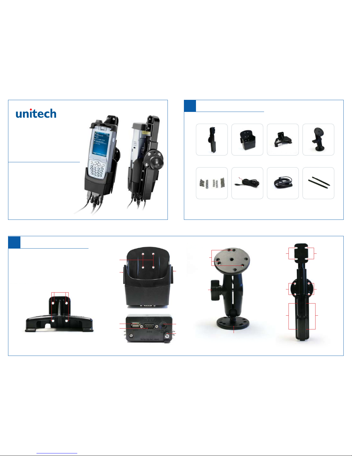
Mounting
Holes
Mounting
Holes
Adjustable
Mounting
Joint
Mounting
Channels
for Power
Dock
Mounting
Channels
for Power
Dock
Mounting
Channels
for Upper
Hood
Mounting
Holes for
Mounting Arm
Mounting
Channels
for Upper
Hood
Mounting
Holes for
Mounting Arm
USB Host Port
Power Port
Drill-Down Base Plate
(Also Available with Suction Cup Base)
Power Cord
Clamp
Serial Port
Power Dock - Upper Hood Power Dock - Cradle (Bottom) Mounting Arm Quick-Draw Universal Holder
Overview
1
Package Contents
Please make sure the following contents are in the PA968 Power Dock Packaging:
If anything appears missing or damaged, please contact a Unitech representative.
PA968 Power Dock
Quick Start Guide
Quick-Draw
Universal Holder
Mounting Hardware
(8 - 1/2” screws with nuts)
(4 - 5/8” screws with nuts)
Power Dock
Cradle
Power Cable
Upper Hood
Lighter Adapter
Ball and Socket
Mounting Arm
Stylus
www.ute.com
(Front)
Mounting
Holes
Stylus
Holder
Stylus
Holder
Page 2
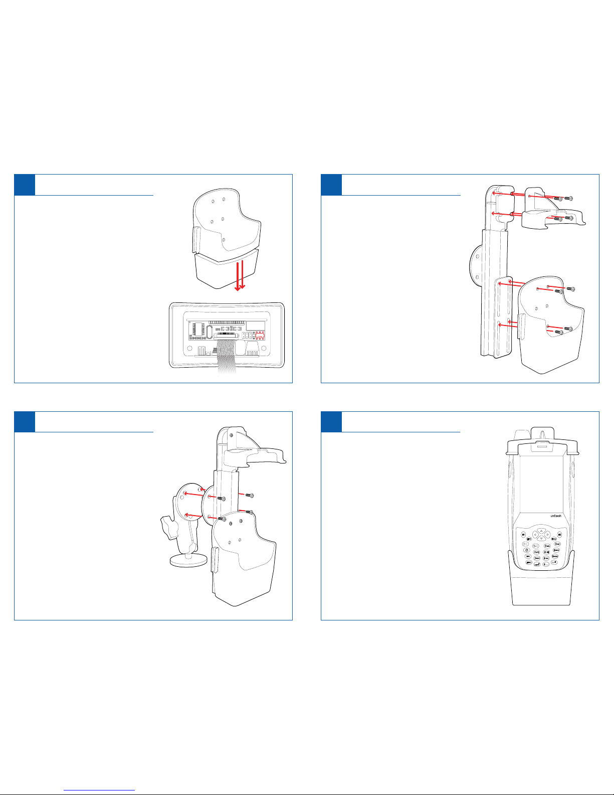
Select Comm Port Attach Power Dock
2 3
Attach Mounting Arm
4
1. Align the mounting holes on the back of
the Quick-Draw Universal Holder with the
mounting holes on the Mounting Arm.
2. Insert four 5/8” pan head screws through
the mounting holes on the Universal
Holder and into the mounting holes on the
Mounting Arm.
3. Tighten the screws using a Phillips head screwdriver and Nylock nuts
(included in package).
1. Align the mounting holes on the Power
Dock with the mounting channels
on the Quick-Draw Universal Holder.
2. For best fit, align the top mounting holes
on the Power Dock Cradle with the very
top of the Universal Holder’s mounting
channels.
3. Insert four 1/2” pan head screws into
the top and bottom mounting holes on the
Power Dock.
4. Push screws through mounting holes and
through mounting channels. Tighten the
screws using a Phillips head screwdriver
and Nylock nuts (included in package).
Insert PA968
5
The PA968 Power Dock utilizes a springloaded arm to hold the unit firmly in place.
1. Place the top of the PA968 into the Upper
Hood (make sure the PA968 antenna is
aligned with opening in the Upper Hood).
Push the PA968 upward to extend the
spring-loaded arm.
2. Raise the PA968 until the bottom of the
device clears the front edge of the Power
Dock. Align the bottom of the PA968 with
the Power Dock cradle and lower the
device into the cradle.
3. The PA968 should be seated firmly in the
Power Dock as shown in the Illustration to
the right.
1. Unscrew the two screws on the bottom of
the Power Dock Cradle (Fig A).
2. Slowly separate the top and bottom sections
of the Power Dock Cradle - the two sections
are connected via internal ribbon cable.
3. Inside the bottom section of the Power Dock
Cradle is the control board and the switch
used to select the comm port (Fig B).
4. Set the switch to the right for the USB host
port or set it to the left for RS232.
*The default switch position is RS232.
(The switch is highlighted in red in Fig B)
5. Reconnect and screw the top and bottom
sections of the Power Dock Cradle back
together.
Fig A
Fig B
 Loading...