

Page 1
2D Imager Scanner
- MS842N -
User’s Manual
Version 0.2
Page 2

Table of Contents
Chapter 1 Getting Started ............................................................................................................................................................ 1
Introduction ...................................................................................................................................................................... 1
About This Guide .............................................................................................................................................................1
Barcode Scanning............................................................................................................................................................2
Programming Barcodes ...................................................................................................................................................2
Factory Defaults............................................................................................................................................................... 3
Custom Defaults...............................................................................................................................................................3
Chapter 2 Communication Interfaces ......................................................................................................................................... 5
Introduction ...................................................................................................................................................................... 5
Serial Communication Interface ....................................................................................................................................... 5
Baud Rate................................................................................................................................................................. 6
Parity Check.............................................................................................................................................................. 7
Data Bit .....................................................................................................................................................................7
Stop Bit .....................................................................................................................................................................8
Hardware Flow Control .............................................................................................................................................8
USB Interface................................................................................................................................................................... 9
USB-DataPipe........................................................................................................................................................... 9
USB HID-KBW .......................................................................................................................................................... 9
USB Country Keyboard Types .................................................................................................................................. 9
Country Code Table (Appendix 5)........................................................................................................................... 10
Beep on Unknown Character .................................................................................................................................. 11
Emulate ALT+Keypad ............................................................................................................................................. 11
Function Key Mapping ............................................................................................................................................ 11
Inter-Keystroke Delay .............................................................................................................................................12
Caps Lock............................................................................................................................................................... 12
Convert Case .......................................................................................................................................................... 13
Emulate Numeric Keypad ....................................................................................................................................... 13
USB COM Port Emulation....................................................................................................................................... 14
HID-POS................................................................................................................................................................. 14
Acquire Scanned Data ............................................................................................................................................15
VID/PID................................................................................................................................................................... 15
IBM SurePOS(Tabletop)..........................................................................................................
IBM SurePOS (Handheld)....................................................................................................................................... 16
................................ 16
Page 3

Chapter 3 Scan Mode................................................................................................................................................................. 17
Trigger Mode..................................................................................................................................................................17
Auto Mode...................................................................................................................................................................... 17
Decode Session Timeout ........................................................................................................................................ 18
Timeout Between Decodes (Same Barcode) .......................................................................................................... 18
Continuous Mode........................................................................................................................................................... 19
Timeout Between Decodes (Same Barcode) .......................................................................................................... 19
Chapter 4 Scanning Preferences ..............................................................................................................................................21
Introduction .................................................................................................................................................................... 21
Regular Mode/Mobile Phone Mode................................................................................................................................ 21
Decode Area .................................................................................................................................................................. 21
Whole Area Decoding .............................................................................................................................................21
Central Area Decoding ............................................................................................................................................22
Specify Central Area ...............................................................................................................................................22
Chapter 5 Illumination & Aiming ............................................................................................................................................... 23
Illumination..................................................................................................................................................................... 23
Aiming ............................................................................................................................................................................24
Chapter 6 Beep & LED Indications ...........................................................................................................................................25
Introduction .................................................................................................................................................................... 25
Startup Beep .................................................................................................................................................................. 25
Beep after Good Decode................................................................................................................................................25
Beep Type............................................................................................................................................................... 26
Beep Volume...........................................................................................................................................................26
Additional Settings for Type 1 .................................................................................................................................27
Beep Duration ......................................................................................................................................................... 27
Beep Frequency...................................................................................................................................................... 28
LED Notification .............................................................................................................................................................29
LED Notification for Good Decode ..........................................................................................................................29
LED Notification Duration for Good Decode......................................................................................
...................... 29
Chapter 7 Data Formatting.........................................................................................................................................................30
Introduction .................................................................................................................................................................... 30
General Settings ............................................................................................................................................................31
Enable/Disable All Prefix/Suffix............................................................................................................................... 31
Prefix Sequences.................................................................................................................................................... 31
AIM ID Prefix.................................................................................................................................................................. 32
Page 4

Code ID Prefix................................................................................................................................................................ 32
Restore All Default Code IDs .................................................................................................................................. 33
Modify Code ID ....................................................................................................................................................... 33
Custom Prefix.................................................................................................................................................................37
Enable/Disable Custom Prefix ................................................................................................................................37
Set Custom Prefix ...................................................................................................................................................37
Custom Suffix................................................................................................................................................................. 38
Enable/Disable Custom Suffix................................................................................................................................. 38
Set Custom Suffix ................................................................................................................................................... 38
Data Packing.................................................................................................................................................................. 39
Normal Pack ...........................................................................................................................................................39
Terminating Character Suffix..........................................................................................................................................40
Enable/Disable Terminating Character Suffix.......................................................................................................... 40
Set Terminating Character Suffix.............................................................................................................................41
Chapter 8 Symbologies..............................................................................................................................................................42
General Settings ............................................................................................................................................................42
Enable/Disable All Symbologies..............................................................................................................................42
Enable/Disable 1D Symbologies............................................................................................................................. 42
Enable/Disable 2D Symbologies............................................................................................................................. 42
1D Symbologies............................................................................................................................................................. 43
Code 128 ................................................................................................................................................................43
Restore Factory Defaults ........................................................................................................................................43
Enable/Disable Code 128 .......................................................................................................................................43
Set Length Range for Code 128 .............................................................................................................................43
GS1-128 (UCC/EAN-128) ....................................................................................................................................... 44
Restore Factory Defaults ........................................................................................................................................44
Enable/Disable GS1-128.........................................................................................................................................44
EAN-8 .....................................................................................................................................................................45
Restore Factory Defaults ........................................................................................................................................45
Enable/Disable EAN-8 ............................................................................................................................................45
Transmit Check Digit............................................................................................................................................... 45
Add-On Code .......................................................................................................................................................... 46
EAN-8 Extension..................................................................................................................................................... 47
EAN-13 ...................................................................................................................................................................48
Restore Factory Defaults ........................................................................................................................................48
Enable/Disable EAN-13 ..........................................................................................................................................48
Transmit Check Digit............................................................................................................................................... 48
Page 5

Add-On Code .......................................................................................................................................................... 49
ISBN .......................................................................................................................................................................50
Restore Factory Defaults ........................................................................................................................................50
Enable/Disable ISBN ..............................................................................................................................................50
Set ISBN Format.....................................................................................................................................................50
UPC-E..................................................................................................................................................................... 51
Restore Factory Defaults ........................................................................................................................................51
Enable/Disable UPC-E............................................................................................................................................ 51
Transmit Check Digit............................................................................................................................................... 51
Add-On Code .......................................................................................................................................................... 52
Transmit System Character “0”............................................................................................................................... 52
UPC-E Extension .................................................................................................................................................... 53
UPC-A..................................................................................................................................................................... 54
Restore Factory Defaults ........................................................................................................................................54
Enable/Disable UPC-A............................................................................................................................................ 54
Transmit Check Digit............................................................................................................................................... 54
Add-On Code .......................................................................................................................................................... 55
Transmit Preamble Character “0”............................................................................................................................ 55
Interleaved 2 of 5 .................................................................................................................................................... 56
Restore Factory Defaults ........................................................................................................................................56
Enable/Disable Interleaved 2 of 5 ........................................................................................................................... 56
Set Length Range for Interleaved 2 of 5 .................................................................................................................56
Parity Check............................................................................................................................................................ 57
Set Discrete Lengths for Interleaved 2 of 5............................................................................................................. 58
ITF-14 ..................................................................................................................................................................... 59
ITF-6 .......................................................................................................................................................................60
Matrix 2 of 5 ............................................................................................................................................................ 61
Restore Factory Defaults ........................................................................................................................................61
Enable/Disable Matrix 2 of 5 ................................................................................................................................... 61
Set Length Range for Matrix 2 of 5 .............................................................................................
............................ 61
Parity Check............................................................................................................................................................ 62
Code 39 ..................................................................................................................................................................63
Restore Factory Defaults ........................................................................................................................................63
Enable/Disable Code 39 .........................................................................................................................................63
Set Length Range for Code 39 ...............................................................................................................................63
Parity Check............................................................................................................................................................ 64
Transmit Start/Stop Character................................................................................................................................. 65
Enable/Disable Code 39 Full ASCII ........................................................................................................................ 65
Page 6

Codabar ..................................................................................................................................................................66
Restore Factory Defaults ........................................................................................................................................66
Enable/Disable Codabar ......................................................................................................................................... 66
Set Length Range for Codabar ............................................................................................................................... 66
Parity Check............................................................................................................................................................ 67
Transmit Start/Stop Character................................................................................................................................. 68
Start/Stop Character Format ................................................................................................................................... 68
Code 93 ..................................................................................................................................................................69
Restore Factory Defaults ........................................................................................................................................69
Enable/Disable Code 93 .........................................................................................................................................69
Set Length Range for Code 93 ...............................................................................................................................69
Parity Check............................................................................................................................................................ 70
GS1-Databar (RSS) ................................................................................................................................................ 71
Restore Factory Defaults ........................................................................................................................................71
Enable/Disable GS1 Databar ..................................................................................................................................71
Transmit Application Identifier “01”.......................................................................................................................... 71
GS1 Composite Code .............................................................................................................................................72
Restore Factory Defaults ........................................................................................................................................72
Enable/Disable GS1 Composite Code ....................................................................................................................72
EAN/UPC Composite.............................................................................................................................................. 72
Code 11................................................................................................................................................................... 73
Restore Factory Defaults ........................................................................................................................................73
Enable/Disable Code 11..........................................................................................................................................73
Set Length Range for Code 11................................................................................................................................73
Transmit Check Digit............................................................................................................................................... 74
Parity Check............................................................................................................................................................ 74
Industrial 2 of 5 ..............................................................................................................
......................................... 75
Restore Factory Defaults ........................................................................................................................................75
Enable/Disable Industrial 2 of 5 ..............................................................................................................................75
Set Length Range for Industrial 2 of 5 ....................................................................................................................75
Parity Check............................................................................................................................................................ 76
Standard 25.............................................................................................................................................................77
Restore Factory Defaults ........................................................................................................................................77
Enable/Disable Standard 25....................................................................................................................................77
Set Length Range for Standard 25..........................................................................................................................77
Parity Check............................................................................................................................................................ 78
Plessey ...................................................................................................................................................................79
Restore Factory Defaults ........................................................................................................................................79
Page 7

Enable/Disable Plessey ..........................................................................................................................................79
Set Length Range for Plessey ................................................................................................................................79
Parity Check............................................................................................................................................................ 80
MSI-Plessey............................................................................................................................................................ 81
Restore Factory Defaults ........................................................................................................................................81
Enable/Disable MSI-Plessey................................................................................................................................... 81
Set Length Range for MSI-Plessey......................................................................................................................... 81
Transmit Check Digit............................................................................................................................................... 82
Parity Check............................................................................................................................................................ 82
2D Symbologies............................................................................................................................................................. 83
PDF 417.................................................................................................................................................................. 83
Restore Factory Defaults ........................................................................................................................................83
Enable/Disable PDF 417......................................................................................................................................... 83
Set Length Range for PDF 417...............................................................................................................................83
PDF 417 Inverse ..................................................................................................................................................... 84
PDF417 Twin Code................................................................................................................................................. 85
QR Code................................................................................................................................................................. 86
Restore Factory Defaults ........................................................................................................................................86
Enable/Disable QR Code........................................................................................................................................ 86
Set Length Range for QR Code .............................................................................................................................. 86
QR Twin Code......................................................................................................................................................... 87
Aztec Code .............................................................................................................................................................88
Restore Factory Defaults ........................................................................................................................................88
Enable/Disable Aztec Code..................................................................................................................................... 88
Set Length Range for Aztec Code........................................................................................................................... 88
Read Multi-barcodes of an Image ...........................................................................................................................89
Set the Number of Barcodes................................................................................................................................... 90
Data Matrix..............................................................................................................................................................91
Restore Factory Defaults .......................................................................................................
................................. 91
Enable/Disable Data Matrix..................................................................................................................................... 91
Set Length Range for Data Matrix........................................................................................................................... 91
Rectangular Barcode .............................................................................................................................................. 92
Data Matrix Inverse.................................................................................................................................................92
Data Matrix Twin Code............................................................................................................................................ 93
Maxicode................................................................................................................................................................. 94
Restore Factory Defaults ........................................................................................................................................94
Enable/Disable Maxicode........................................................................................................................................94
Set Length Range for Maxicode.............................................................................................................................. 94
Page 8

Chinese Sensible Code...........................................................................................................................................95
Restore Factory Defaults ........................................................................................................................................95
Enable/Disable Chinese Sensible Code ................................................................................................................. 95
Set Length Range for Chinese Sensible Code........................................................................................................ 95
Chinese Sensible Code Inverse.............................................................................................................................. 96
Chapter 9 Troubleshooting........................................................................................................................................................ 97
FAQ................................................................................................................................................................................ 97
Appendix ..................................................................................................................................................................................... 99
Appendix 1: Factory Defaults Table................................................................................................................................99
Appendix 2: AIM ID Table.............................................................................................................................................105
Appendix 3: Code ID Table...........................................................................................................................................106
Appendix 4: ASCII Table...............................................................................................................................................107
Appendix 5: Country Code Table...................................................................................................................................111
Appendix 6: ASCII Function Key Mapping Table .......................................................................................................... 112
Appendix 7: Symbology ID Number ............................................................................................................................. 114
Appendix 8: Parameter Programming Examples ......................................................................................................... 115
a. Program the Decode Session Timeout.............................................................................................................. 115
b. Program the Timeout between Decodes (Same Barcode)................................................................................ 115
c. Program the Central Area.................................................................................................................................. 115
d. Program the Duration of Good Decode Beep (Type 1) ..................................................................................... 116
e. Program the Frequency of Good Decode Beep (Type 1).................................................................................. 116
f. Program the LED Notification Duration for Good Decode.................................................................................. 116
g. Program the Custom Prefix/Suffix..................................................................................................................... 117
h. Program the Terminating Character Suffix ........................................................................................................ 117
i. Program the Code ID ......................................................................................................................................... 117
j. Program the Length Range (Maximum/Minimum Lengths) for a Symbology ..................................................... 118
k. Program the Discrete Lengths for Interleaved 2 of 5......................................................................................... 119
Appendix 9: F-Key Barcodes........................................................................................................................................120
Appendix 10: Digit Barcodes........................................................................................................................................ 122
Appendix 11: Save/Cancel Barcodes ........................................................................................................................... 124
Page 9

Enter Setup
Chapter 1 Getting Started
Introduction
The MS842N series embedded 2D barcode scan engines are armed with CMOS image capturer, featuring fast scanning
and accurate decoding on barcodes on virtually any medium - paper, magnetic card, mobile phones and LCD displays.
About This Guide
This guide provides programming instructions for the MS842N. Users can configure the MS842N by scanning the
programming barcodes included in this manual.
The MS842N has been properly configured for most applications and can be put into use without further configuration.
Users may check the Factory Defaults Table in Appendix for reference. Throughout the manual, programming barcodes
marked with asterisks (**) are factory default values.
.
1 **Exit Setup
Page 10

Enter Setup
Barcode Scanning
The MS842N feasures fast scanning and decoding accuracy. Barcodes rotated at any angle can still be read with ease.
When scanning a barcode, simply center the aiming beam or pattern projected by the MS842N over the barcode.
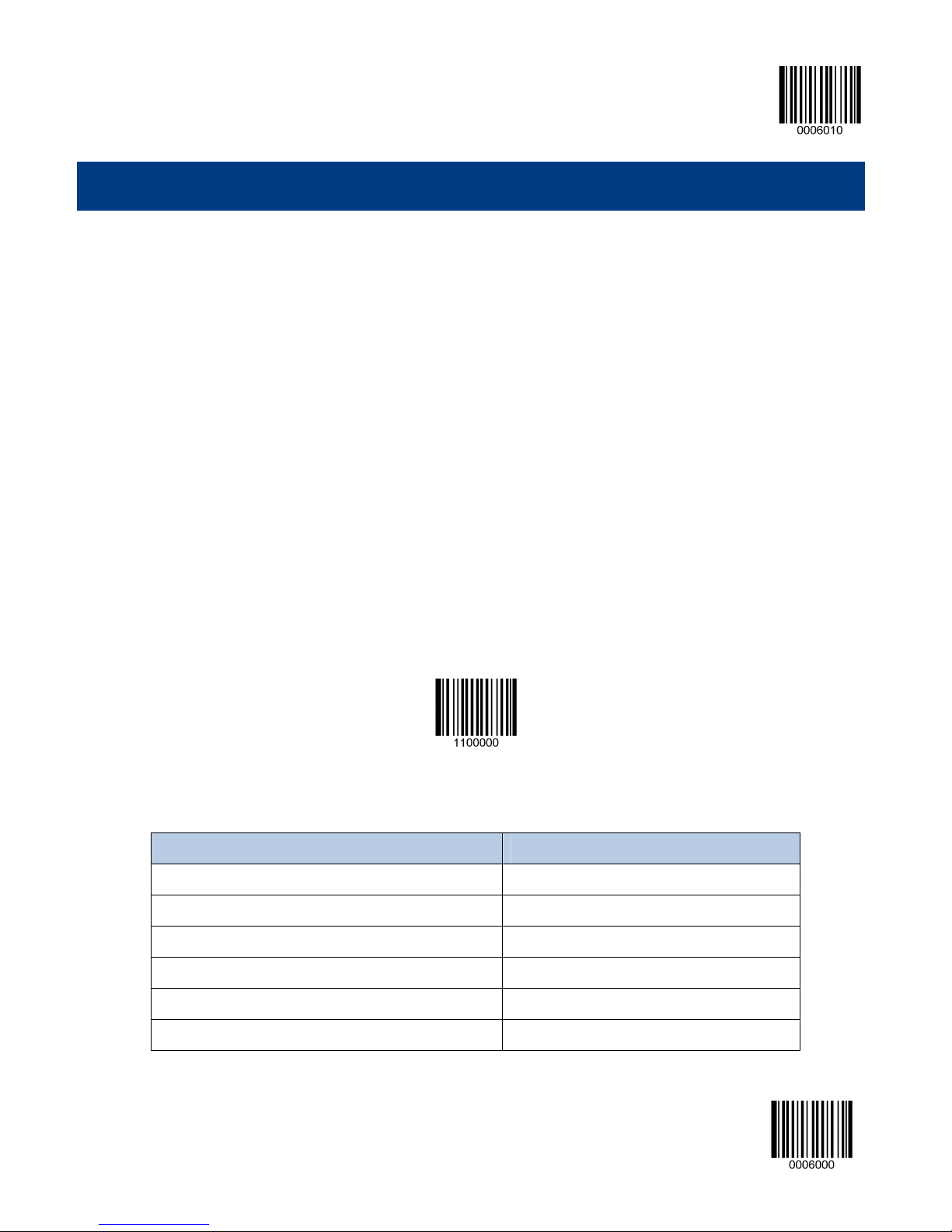
Programming Barcodes
Scanning the Enter Setup barcode can enable the engine to enter the setup mode. Then you can scan a number of
programming barcodes to configure your engine. To exit the setup mode, scan the Exit Setup barcode.
If the engine has exit the setup mode, only some special programming barcodes, such as the Enter Setup barcode and
Restore All Factory Defaults barcode, can be read.
Enter Setup
** Exit Setup
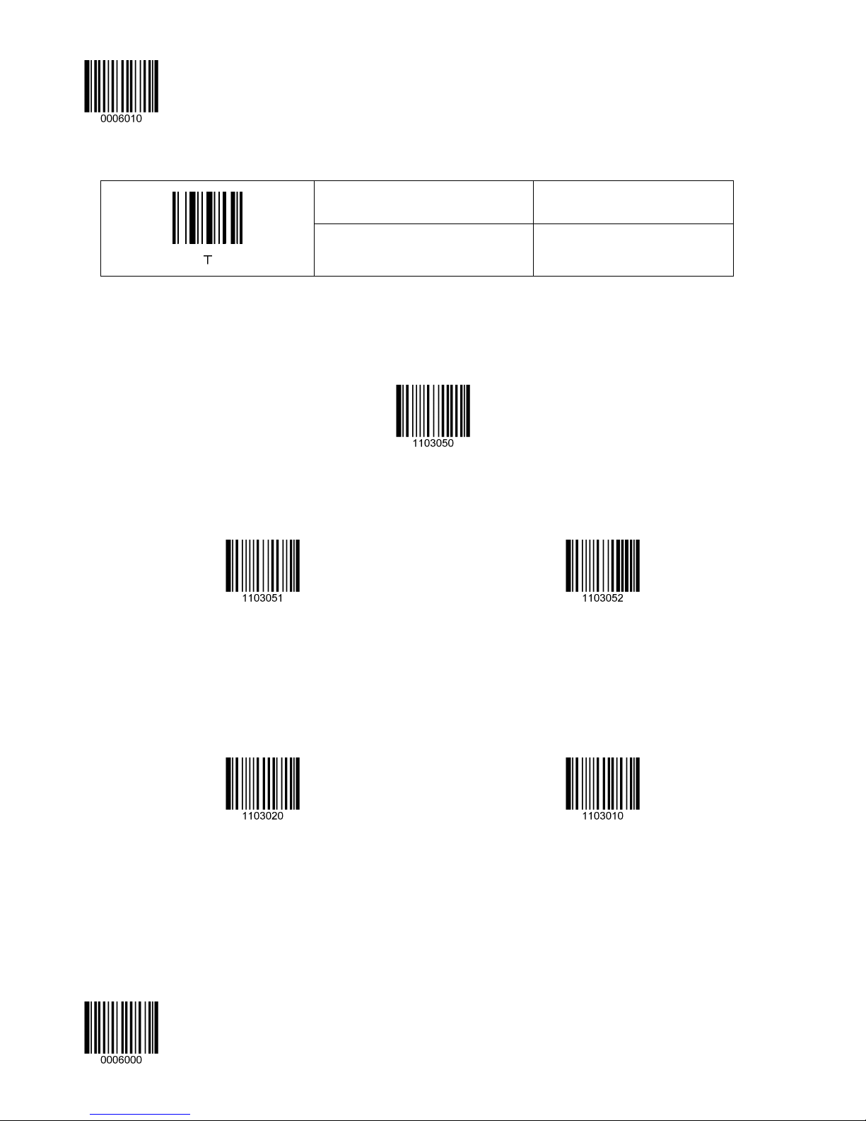
Programming barcode data can be transmitted to the Host. Scan the appropriate barcode below to enable or disable the
transmission of programming barcode data (programming commands) to the Host.
Transmit Programming Barcode Data
** Do Not Transmit Programming Barcode Data
** Exit Setup 2
Page 11

Enter Setup
Factory Defaults
Scanning the following barcode can restore the engine to the factory defaults. See Appendix 1: Factory Defaults Table for
more information.
Restoring the engine to factory defaults will not remove custom defaults stored on the engine.
Restore All Factory Defaults
Note: Use this feature with discretion.
Custom Defaults
Scanning the Restore All Custom Defaults barcode can reset all parameters to the custom defaults. Scanning the Save as
Custom Defaults can set the current settings as custom defaults.
Custom defaults are stored in the non-volatile memory.
Save as Custom Defaults
Restore All Custom Defaults
3 **Exit Setup
Page 12

Enter Setup
** Exit Setup 4
Page 13
Enter Setup
Chapter 2 Communication Interfaces
Introduction
The MS842N engine provides a TTL-232 interface and a USB interface to communicate with the host device. The host
device can receive scanned data and send commands to control the engine or to access/alter the configuration
information of the engine via the TTL-232 or USB interface.
Serial Communication Interface
Serial communication interface is usually used when connecting the engine to a host device (like PC, POS). However, to
ensure smooth communication and accuracy of data, you need to set communication parameters (including baud rate,
parity check, data bit and stop bit) to match the host device.
The serial communication interface provided by the engine is based on TTL signals. TTL-232 can be used for most
application architectures. For those requiring RS-232, an external conversion circuit is needed. The conversion circuit is
available only to some models.
Serial Communication
Default serial communication parameters are listed below. Make sure all parameters match the host requirements.
Parameter Factury Default
Serial Communication Standard TTL-232
Baud Rate 9600
Parity Check None
Data Bits 8
Stop Bits 1
Hardware Auto Flow Control None
5 **Exit Setup
Page 14

Enter Setup
Baud Rate
Baud rate is the number of bits of data transmitted per second. Set the baud rate to match the Host requirements.
** Baud Rate 9600
Baud Rate 1200
Baud Rate 2400
Baud Rate 19200
Baud Rate 38400
Baud Rate 57600
Baud Rate 4800
Baud Rate 14400
** Exit Setup 6
Baud Rate 115200
Page 15

Enter Setup
Parity Check
Even Parity
** None
Odd Parity
Data Bit
** 8 Data Bits
7 Data Bits
6 Data Bits
5 Data Bits
7 **Exit Setup
Page 16

Enter Setup
Stop Bit
** 1 Stop Bit
2 Stop Bits
Hardware Flow Control
If this feature is enabled, the engine determines whether to transmit data based on CTS signal level. When CTS signal is at
a low level which means the serial port’s cache memory of receiving device (such as PC) is full, the engine sends data
through RS-232 port until CTS signal is set to high level by receiving device. When the engine is not ready for receiving, it
will set RTS signal to low level. When sending device (such as PC) detects it, it will not send data to the engine any more to
prevent data loss.
If this feature is disabled, reception/transmission of serial data will not be influenced by RTS/CTS signal.
Enable Hardware Flow Control
** Disable Hardware Flow Control
Note: Before enabling this feature, make sure that RTS/CTS signal line is contained in RS-232 cable. Without the signal
line, serial communication errors will occur.
** Exit Setup 8
Page 17

Enter Setup
USB Interface
USB-DataPipe
A driver is required when using this protocol to communicate with the engine. Its advantages include fast data transmissoin
and easy to use.
USB HID-KBW
When you connect the engine to the Host via a USB connection, you can enable the USB HID-KBW feature by scanning
the barcode below. Then engine’s transmission will be simulated as USB keyboard input. The Host receives keystrokes on
the virtual keyboard. It works on a Plug and Play basis and no driver is required.
USB-Datapipe
USB HID-KBW
USB Country Keyboard Types
Keyboard layouts and country codes vary from country to country. All supported keyboard types are listed in the Country
Code Table. The default setting is US keyboard type.
To learn how to select a keyboard type, see the example below.
Select Country Code
9 **Exit Setup
Page 18

Enter Setup
Country Code Table (Appendix 5)
Country/Language Code Country/Language Code
U.S. 0 Netherlands(Dutch) 14
Belgium 1 Norway 15
Brazil 2 Poland 16
Canada(French) 3 Portugal 17
Czechoslovakia 4 Romania 18
Denmark 5 Russia 19
Finland(Swedish) 6 Slovakia 21
France 7 Spain 22
Germany/Austria 8 Sweden 23
Greece 9 Switzerland(German) 24
Hungary 10 Turkey F 25
Israel(Hebrew) 11 Turkey Q 26
Italy 12 U.K 27
Latin-American 13 Japan 28
Example: Program the engine to emulate Norwegian keyboard (Norway)
1. Scan the Enter Setup barcode.
2. Scan the Select Country Code barcode.
3. Check the country code for Norway in the Country Code Table. (Norway: 15)
4. Scan the numeric barcodes “1” and “5”.
5. Scan the Save barcode.
6. Scan the Exit Setup barcode.
** Exit Setup 10
Page 19

Enter Setup
Beep on Unknown Character
Due to the differences in keyboard layouts, some characters contained in barcode data may be unavailable on the selected
keyboard. As a result, the engine fails to transmit the unknown characters.
Scan the appropriate barcode below to enable or disable the emission of beep when an unknown character is detected.
Beep on Unknown Character
** Do Not Beep on Unknown Character
Emulate ALT+Keypad
When Emulate ALT+Keypad is turned on, any ASCII character (0x00 - 0xff) is sent over the numeric keypad no matter
which keyboard type is selected. Since sending a character involves multiple keystroke emulations, this method appears
less efficient.
Emulate ALT+Keypad ON
** Emulate ALT+Keypad OFF
Function Key Mapping
When Function Key Mapping is enabled, function character (0x00 - 0x1F) are sent as ASCII sequences over the numeric
keypad. For more information, see Appendix 6: ASCII Function Key Mapping Table
A shortcut to send a function key (F1-F12) is to scan the corresponding barcode in Appendix 9: F-Key Barcodes.
.
Note: Emulate ALT+Keypad ON prevails over Enable Function Key Mapping.
Enable Function Key Mapping
11 **Exit Setup
** Disable Function Key Mapping
Page 20
Enter Setup
Example: Barcode data 0x16
Enable Function Key Mapping
Disable Function Key Mapping
Inter-Keystroke Delay
This parameter specifies the delay between emulated keystrokes.
** No Delay
Short Delay (20ms)
Ctrl +V
F1
Long Delay (40ms)
Caps Lock
The Caps Lock ON option can invert upper and lower case characters contained in barcode data. This inversion occurs
regardless of the state of Caps Lock key on the Host’s keyboard.
Caps Lock ON
** Caps Lock OFF
Note: Emulate ALT+Keypad ON/ Convert All to Upper Case/ Convert All to Lower Case prevails over Caps Lock ON.
Example: When the Caps Lock ON is selected, barcode data “AbC” is transmitted as “aBc”.
** Exit Setup 12
Page 21

Convert Case
Scan the appropriate barcode below to convert all bar code data to your desired case.
** No Case Conversion
Enter Setup
Convert All to Upper Case
Convert All to Lower Case
Example: When the Convert All to Lower Case feature is enabled, barcode data “AbC” is transmitted as “abc”.
Emulate Numeric Keypad
When this feature is disabled, sending barcode data is emulated as keystroke(s) on main keyboard.
To enable this feature, scan the Emulate Numeric Keypad barcode. Sending a number (0-9) is emulated as keystroke(s)
on numeric keypad, whereas sending other character like “+”, “_”, “*” , “/” and “.” is still emulated as keystrokes on main
keyboard.
Numeric keypad is usually situated at the right of the main keyboard. The state of Num Lock on the simulated numeric
keypad is determined by its equivalent on the Host. If Num Lock on the Host is turned off, the output of simulated numeric
keypad is function key instead of number.
Emulate Numeric Keypad
** Do Not Emulate Numeric Keypad
Note: Make sure the Num Lock light of the Host is turned ON before enabling this feature.
Simulate ALT+Keypad ON prevails over Emulate Numeric Keypad.
13 **Exit Setup
Page 22

Enter Setup
Example: Supposing the Emulate Numeric Keypad feature is enabled:
if Num Lock on the Host is ON, “A4.5” is transmitted as “A4.5”;
if Num Lock on the Host is OFF, “A4.5” is transmitted as follows:
1. “A” is sent as is because it is not included in numeric keypad;
2. “4” is sent as the function key “Cursor Move to Left”;
3. “.” is sent as the function key “Delete After the Cursor”;
4. “5” is not sent as it does not correspond to any function key.
USB COM Port Emulation
If you connect the engine to the Host via a USB connection, the USB COM Port Emulation feature allows the Host to
receive data in the way as a serial port does. However, you need to set communication parameters on the engine to match
the Host requirements.
USB COM Port Emulation
HID-POS
The HID-POS interface is recommended for new application programs. It can send up to 56 characters in a single USB
report and appears more efficient than keyboard emulation.
Features:
HID based, no custom driver required.
Way more efficient in communication than keyboard emulation and traditional RS-232 interface.
Note: HID-POS does not require a custom driver. However, a HID interface on Windows 98 does. All HID interfaces
employ standard driver provided by the operating system. Use defaults when installing the driver.
HID-POS
** Exit Setup 14
Page 23

Access the engine with your program:
1. Use CreateFile to access the engine as a HID device.
2. Use ReadFile to deliver the scanned data to the application program.
3. Use WriteFile to send data to the engine.
Enter Setup
For detailed information about USB and HID interfaces, go to www.USB.org
.
Acquire Scanned Data
After a barcode is decoded, the engine sends an input report as below:
Bit
Byte 7 6 5 4 3 2 1 0
0
1
2-57
58-61
62
63 - - - - - - -
Symbology ID Number (Appendix 7) or N/C: 0x00
Report ID = 0x02
Barcode Length
Decoded Data (1-56)
Reserved (1-4)
Decode Data
Continued
VID/PID
USB uses VID (Vendor ID) and PID (Product ID) to identify and locate a device. The VID is assigned by USB
Implementers Forum. Every PID contains a base number and interface type (keyboard, COM port, etc.).
Product Interface PID (Hex) PID (Dec)
MS842N
15 **Exit Setup
Base 0000 0
HID-POS 0010 16
Page 24

Enter Setup
IBM SurePOS(Tabletop)
IBM SurePOS (Handheld)
IBM-SurePOS (Table-Top)
IBM-SurePOS (Hand-Held)
** Exit Setup 16
Page 25

Enter Setup
Chapter 3 Scan Mode
Trigger Mode
If the Trigger Mode is enabled, receiving a valid trigger signal activates a decode session. The session continues until the
barcode is decoded as long as the trigger signal remains valid; the session stops when the signal becomes invalid. For good
decode, the engine transmits decoded data via communication port. To activate another session, the Host first terminates
the trigger signal, waits 20ms or longer and then makes the signal valid.
Trigger Mode
Auto Mode
If the Auto Mode is enabled, the engine activates a decode session every time it detects a change in ambient illumination.
The decode session continues until the barcode is decoded or the Decode Session Timeout occurs.
Receiving a trigger signal can also activate a decode session. The decode session continues until the trigger signal
becomes invalid or the barcode is decoded or the Decode Session Timeout occurs. The trigger signal needs to be
terminated before the engine is able to monitor ambient illumination again.
** Auto Mode
17 **Exit Setup
Page 26

Enter Setup
Decode Session Timeout
This parameter sets the maximum time decode session continues during a scan attempt in the Auto Mode. It is
programmable in 1ms increments from 500ms to 3600000ms. The default timeout is 3000ms. To learn how to program this
parameter, see the “a. Program the Decode Session Timeout” section in Appendix.
Decode Session Timeout
Timeout Between Decodes (Same Barcode)
In order not to decode a barcode repeatedly, you can program this parameter to prevent the engine from rereading the
same barcode in a given period of time.
This parameter sets the timeout between decodes for the same barcode in the Auto Mode. It is programmable in 1ms
increments from 1ms to 3600000ms. The default timeout is 1500ms.
To learn how to program this parameter, see the “b. Program the Timeout between Decodes (Same Barcode)” section
in Appendix.
Timeout Between Decodes (Same Barcode)
Disable Timeout Between Decodes: Allow the engine to re-read the same barcode.
Enable Timeout Between Decodes: Do not allow the engine to re-read the same barcode before the Timeout Between
Decodes (Same Barcode) occurs.
** Disable Timeout Between Decodes
Enable Timeout Between Decodes
** Exit Setup 18
Page 27

Continuous Mode
Enter Setup
This mode enables the engine to scan/capture, decode and transmit over and over again.
If the Continuous Mode is enabled, the engine activates/suspends/resumes barcode reading through control over the
trigger signal. When barcode reading is in progress, terminating the trigger signal after having kept it valid for 30ms or
longer will suspend barcode reading; when barcode reading is suspended, performing the same control over the trigger
signal will resume barcode reading.
Continuous Mode
Timeout Between Decodes (Same Barcode)
In order not to decode a barcode repeatedly, you can program this parameter to prevent the engine from rereading the
same barcode in a given period of time.
This parameter sets the timeout between decodes for the same barcode in the Continuous Mode. It is programmable in 1ms
increments from 1ms to 3600000ms. The default timeout is 1500ms.
To learn how to program this parameter, see the “b. Program the Timeout between Decodes (Same Barcode)” section
in Appendix.
Disable Timeout Between Decodes: Allow the engine to re-read the same barcode.
Enable Timeout Between Decodes: Do not allow the engine to re-read the same barcode before the Timeout Between
Decodes (Same Barcode) occurs.
19 **Exit Setup
Timeout Between Decodes (Same Barcode)
Page 28

Enter Setup
** Disable Timeout Between Decodes
Enable Timeout Between Decodes
** Exit Setup 20
Page 29

Enter Setup
Chapter 4 Scanning Preferences
Introduction
This chapter contains information as to how to adapt your engine to various applications with preference setting. For
instance, to improve barcode reading performance off mobile phones and LCD displays; or to narrow the field of view of the
engine to make sure it reads only those barcodes intended by the user.
Regular Mode/Mobile Phone Mode
The engine can capture barcodes printed on paper labels or displayed on the screen of a mobile phone. Select a mode as
per actual need.
Regular Mode: Read barcodes printed on paper or plastic.
Mobile Phone Mode: Read barcodes off mobile phones or LCD displays.
** Regular Mode
Mobile Phone Mode
Decode Area
Whole Area Decoding
When this option is enabled, the engine attempts to decode barcode(s) within its field of view, from the center to the
periphery, and transmits the barcode that has been first decoded.
** Whole Area Decoding
21 **Exit Setup
Page 30
Enter Setup
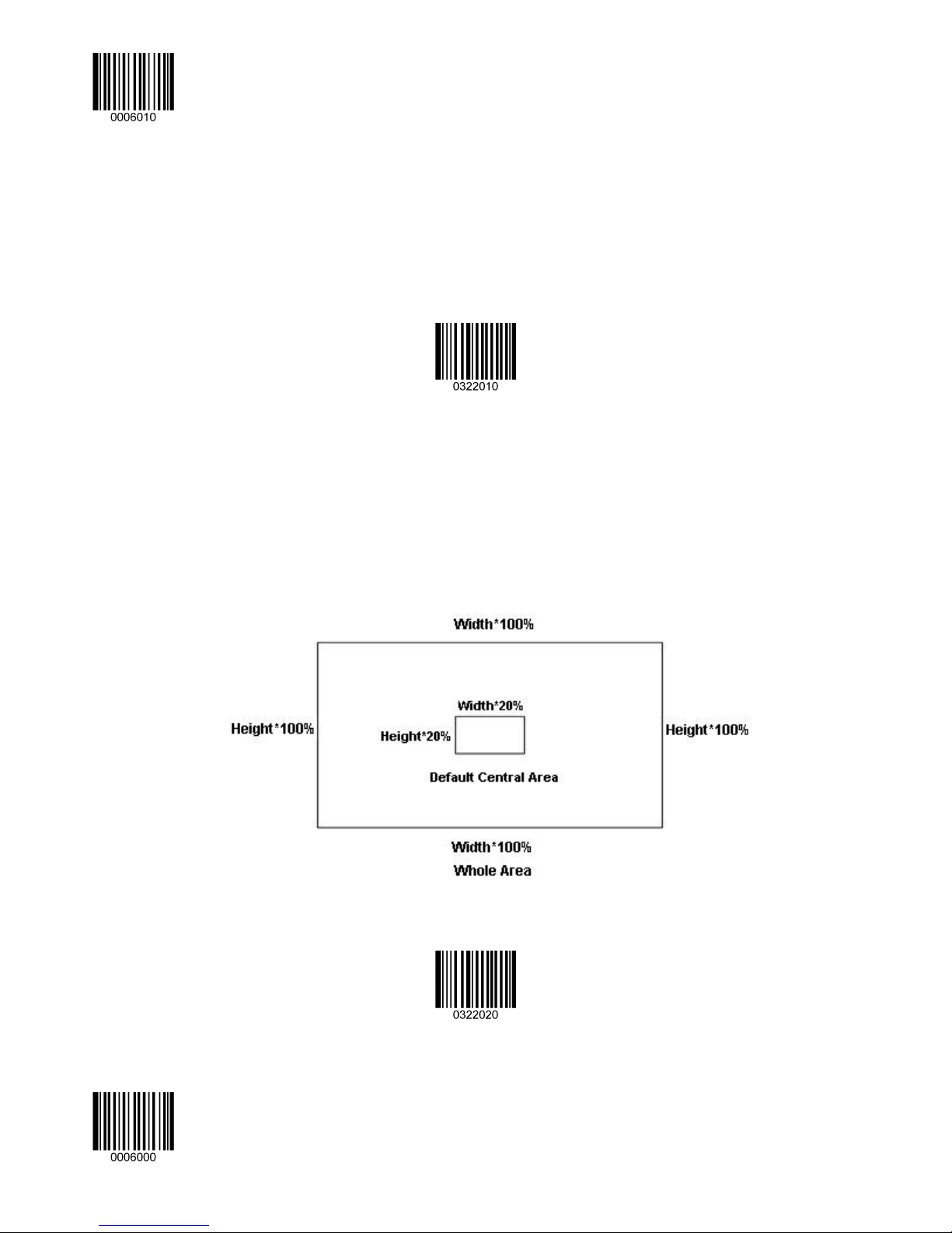
Central Area Decoding
The engine attempts to decode barcode(s) within a specified central area and transmits the barcode that has been first
decoded. This option allows the engine to narrow its field of view to make sure it reads only those barcodes intended by the
user. For instance, if multiple barcodes are placed closely together, central area decoding in conjunction with appropriate
pre-defined central area will insure that only the desired barcode is read.
Central Area Decoding
Specify Central Area
The default central area is a (Width*20%) by (Height*20%) area in the center of the engine’s field of view, as shown in the
figure below. You can define the central area by scanning the Specify Central Area barcode and numeric barcode(s)
corresponding to a desired percentage (1-100). If Central Area Decoding is enabled by scanning the Central Area
Decoding barcode, the engine only reads barcodes that intersect the predefined central area.
To learn how to program this parameter, see the “c. Program the Central Area” section in Appendix.
** Exit Setup 22
Specify Central Area
Page 31

Illumination
Enter Setup
Chapter 5 Illumination & Aiming
A couple of illumination options are provided to improve the lighting conditions during every image capture:
Normal: Illumination LEDs are turned on during image capture.
Always ON: Illumination LEDs keep ON after the engine is powered on.
OFF: Illumination LEDs are OFF all the time.
** Normal
OFF
Always ON
23 **Exit Setup
Page 32

Enter Setup
Aiming
When scanning/capturing image, the engine projects an aiming pattern which allows positioning the target barcode within its
field of view and thus makes decoding easier.
Normal: The engine projects an aiming pattern only during barcode scanning/capture.
Always ON: Aiming pattern is constantly ON after the engine is powered on.
OFF: Aiming pattern is OFF all the time.
** Normal
OFF
Always ON
** Exit Setup 24
Page 33

Enter Setup
Chapter 6 Beep & LED Indications
Introduction
Besides communication output, the engine can also generate a PWM signal and a pulse signal. Those outputs in
conjunction with external circuits are able to drive the beeper/LED indicator.
This chapter describes how to program the beep/LED notification feature.
Startup Beep
If startup beep is enabled, the engine will beep after being turned on.
** Enable Startup Beep
Disable Startup Beep
Beep after Good Decode
The engine can be configured to beep after good decode. Beep type (frequency) and volume (duty circle of PWM) are also
user programmable.
** Beep after Good Decode
Do Not Beep after Good Decode
25 **Exit Setup
Page 34

Enter Setup
Beep Type
Beep Volume
** Type 1
Typ e 3
Typ e 2
** Loud
** Exit Setup 26
Low
Medium
Page 35

Enter Setup
Additional Settings for Type 1
Beep duration and frequency settings are designed only for Type 1 (which is a single tone) to serve specific applications.
Beep Duration
** 80ms
40ms
To learn how to program the parameter, see the “d. Program the Duration of Good Decode Beep (Type 1)” section in
Appendix.
Custom (20~300ms)
27 **Exit Setup
Page 36

Enter Setup
Beep Frequency
800Hz
** 2730Hz
1600Hz
4200Hz
You may select the frequency same as the center frequency of your buzzer. To learn how to program this parameter, see the
“e. Program the Frequency of Good Decode Beep (Type 1)” section in Appendix.
** Exit Setup 28
Custom (20~20000 Hz)
Page 37

LED Notification
LED Notification for Good Decode
Note: This feature is applicable to all scan modes.
Enter Setup
Good Decode LED Notification OFF
LED Notification Duration for Good Decode
** Short (20ms)
Long (220ms)
** Good Decode LED Notification ON
Medium (120ms)
Prolonged (320ms)
To learn how to program this parameter, see the “f. Program the LED Notification Duration for Good Decode” section in
Appendix.
29 **Exit Setup
Custom (1 - 10000ms)
Page 38

Enter Setup
Chapter 7 Data Formatting
Introduction
In many applications, barcode data needs to be edited and distinguished from one another.
Usually AIM ID and Code ID can be used as identifiers, but in some special cases customized prefix and terminating
character suffix like Carriage Return or Line Feed can also be the alternatives.
Data editing refers to appending prefix/suffix, data packing, etc.
Data formatting may include:
Append AIM ID/Code ID/custom prefix before the decoded data
Append custom suffix after the decoded data
Pack data
Append terminating character to the end of the data
** Exit Setup 30
Page 39

Enter Setup
General Settings
Enable/Disable All Prefix/Suffix
Disable All Prefix/Suffix: Transmit barcode data with no prefix/suffix.
Enable All Prefix/Suffix: Allow user to append Code ID prefix, AIM ID prefix, custom prefix/suffix and terminating character
to the barcode data before the transmission.
Enable All Prefix/Suffix
Prefix Sequences
**Code ID+Custom Prefix+AIM ID
** Disable All Prefix/Suffix
Custom Prefix+Code ID+AIM ID
31 **Exit Setup
Page 40

Enter Setup
AIM ID Prefix
AIM (Automatic Identification Manufacturers) IDs and ISO/IEC 15424 standards define symbology identifiers and data
carrier identifiers. (For the details, see the “Appendix 2: AIM ID Table” section). If AIM ID prefix is enabled, the engine will
add the symbology identifier before the scanned data after decoding.
Enable AIM ID Prefix
** Disable AIM ID Prefix
Code ID Prefix
Code ID can also be used to identify barcode type. Unlike AIM ID, Code ID is user programmable. Code ID can only consist
of one or two English letters.
Enable Code ID Prefix
** Disable Code ID Prefix
** Exit Setup 32
Page 41

Restore All Default Code IDs
Enter Setup
For the information of default Code IDs, see the “Appendix 3: Code ID Table” section.
Restore All Default Code IDs
Modify Code ID
Code ID of each symbology can be programmed separately. See the following example to learn how to program a Code ID.
Example: Set the Code ID of PDF417 to “p”
1. Check the hex value of “p” in the Appendix 4: ASCII Table. (“p”: 70)
2. Scan the Enter Setup barcode.
3. Scan the Modify PDF417 Code ID barcode.
4. Scan the numeric barcodes “7” and “0”.
5. Scan the Save barcode.
6. Scan the Exit Setup barcode.
33 **Exit Setup
Page 42

Enter Setup
Modify PDF 417 Code ID
Modify QR Code ID
Modify Aztec Code ID
Modify Data Matrix Code ID
Modify Maxicode Code ID
Modify Chinese Sensible Code ID
Modify EAN-8 Code ID
Modify UPC-E Code ID
** Exit Setup 34
Modify EAN-13 Code ID
Modify UPC-A Code ID
Page 43

Enter Setup
Modify Code 128 Code ID
Modify Code 39 Code ID
Modify Interleaved 2 of 5 Code ID
Modify UCC/EAN-128 Code ID
Modify Code 93 Code ID
Modify ITF-14 Code ID
Modify ITF-6 Code ID
Modify Industrial 25 Code ID
35 **Exit Setup
Modify Codabar Code ID
Modify Standard 25 Code ID
Page 44

Enter Setup
Modify Code 11 Code ID
Modify MSI-Plessey Code ID
Modify Composite Code ID
Modify Plessey Code ID
Modify GS1 Databar Code ID
Modify ISBN Code ID
** Exit Setup 36
Page 45

Custom Prefix
Enable/Disable Custom Prefix
Enter Setup
If custom prefix is enabled, you are allowed to append to the data a user-defined prefix that cannot exceed 10 characters.
Enable Custom Prefix
** Disable Custom Prefix
Set Custom Prefix
To set a custom prefix, scan the Set Custom Prefix barcode and then the numeric barcodes corresponding to the
hexadecimal value of a desired prefix. To save the settings, scan the Save barcode.
Note: A custom prefix cannot exceed 10 characters.
Set Custom Prefix
Example: Set the custom prefix to “CODE”
1. Check the hex values of “CODE” in the ASCII Table. (“CODE”: 43, 4F, 44, 45)
2. Scan the Enter Setup barcode.
3. Scan the Set Custom Prefix barcode.
4. Scan the numeric barcodes “4”, “3”, “4”, “F”, “4”, “4”, “4” and “5”.
5. Scan the Save barcode.
6. Scan the Exit Setup barcode.
37 **Exit Setup
Page 46

Enter Setup
Custom Suffix
Enable/Disable Custom Suffix
If custom suffix is enabled, you are allowed to append to the data a user-defined suffix that cannot exceed 10 characters.
Enable Custom Suffix
** Disable Custom Suffix
Set Custom Suffix
To set a custom suffix, scan the Set Custom Suffix barcode and then the numeric barcodes corresponding to the
hexadecimal value of a desired suffix. To save the settings, scan the Save barcode.
Note: A custom suffix cannot exceed 10 characters.
Set Custom Suffix
Example: Set the custom suffix to “CODE”
1. Check the hex values of “CODE” in the ASCII Table. (“CODE”: 43, 4F, 44, 45)
2. Scan the Enter Setup barcode.
3. Scan the Set Custom Suffix barcode.
4. Scan the numeric barcodes “4”, “3”, “4”, “F”, “4”, “4”, “4” and “5”.
5. Scan the Save barcode.
6. Scan the Exit Setup barcode.
** Exit Setup 38
Page 47

Data Packing
For some applications that require high data integrity and reliability, data packing can help you accomplish that.
Transmission of packed data needs to work with certain software on the Host.
Data packing influences data format and is not recommended for general applications.
** Disable Data Packing
Normal Pack
Normal Pack format: [STX + ATTR + LEN] + [AL_TYPE + DATA] + [LRC]
Enter Setup
STX: 0x02
ATTR: 0x00
LEN: Barcode data length is expressed in 2 bytes, ranging from 0 to 65535.
AL_TYPE: 0x36
DATA: Raw barcode data.
LRC: Check digit.
LRC calculation algorithm: computation sequence: 0xFF+LEN+AL_TYPE+DATA; computation method is XOR, byte by
byte.
Normal Pack
39 **Exit Setup
Page 48

Enter Setup
Terminating Character Suffix
A terminating character can be used to mark the end of data, which means nothing can be added after it.
A terminating character suffix can contain one or two characters.
Enable/Disable Terminating Character Suffix
To enable/disable terminating character suffix, scan the appropriate barcode below.
Enable Terminating Character Suffix
** Disable Terminating Character Suffix
** Exit Setup 40
Page 49

Enter Setup
Set Terminating Character Suffix
The engine provides a shortcut for setting the terminating character suffix to 0x0D or 0x0D,0x0A by scanning the following
barcode.
Terminating Character 0x0D
Terminating Character 0x0D,0x0A
To set a terminating character suffix, scan the Set Terminating Character Suffix barcode and then the numeric barcodes
corresponding to the hexadecimal value of a desired terminating character. To save the settings, scan the Save barcode.
Note: A terminating character suffix cannot exceed 2 characters.
Set Terminating Character Suffix
Example: Set the terminating character suffix to 0x0D
1. Scan the Enter Setup barcode.
2. Scan the Set Terminating Character Suffix barcode.
3. Scan the numeric barcodes “0” and “D”.
4. Scan the Save barcode.
5. Scan the Exit Setup barcode.
41 **Exit Setup
Page 50

Enter Setup
Chapter 8 Symbologies
General Settings
Enable/Disable All Symbologies
If the Disable All Symbologies feature is enabled, the engine will not be able to read any non-programming barcodes
except the programming barcodes.
Enable All Symbologies
Enable/Disable 1D Symbologies
Enable 1D Symbologies
Enable/Disable 2D Symbologies
Disable All Symbologies
Disable 1D Symbologies
Enable 2D Symbologies
** Exit Setup 42
Disable 2D Symbologies
Page 51

1D Symbologies
Code 128
Restore Factory Defaults
Enable/Disable Code 128
Enter Setup
Restore the Factory Defaults of Code 128
** Enable Code 128
Disable Code 128
Set Length Range for Code 128
The engine can be configured to only decode Code 128 barcodes with lengths that fall between (inclusive) the minimum
and maximum lengths. To accomplish it, you need to set the minimum and maximum lengths.
For more information, see the “j. Program the Length Range (Maximum/Mininum Lengths) for a Symbology” section
in Appendix.
Set the Minimum Length (Default: 1)
Set the Maximum Length (Default: 48)
43 **Exit Setup
Page 52

Enter Setup
GS1-128 (UCC/EAN-128)
Restore Factory Defaults
Enable/Disable GS1-128
Restore the Factory Defaults of GS1-128
** Enable GS1-128
Disable GS1-128
** Exit Setup 44
Page 53

EAN-8
Restore Factory Defaults
Enable/Disable EAN-8
Enter Setup
Restore the Factory Defaults of EAN-8
** Enable EAN-8
Disable EAN-8
Transmit Check Digit
EAN-8 is 8 digits in length with the last one as its check digit used to verify the accuracy of the data.
** Transmit EAN-8 Check Digit
Do Not Transmit EAN-8 Check Digit
45 **Exit Setup
Page 54

Enter Setup
Add-On Code
An EAN-8 barcode can be augmented with a two-digit or five-digit add-on code to form a new one. In the examples below,
the part surrounded by blue dotted line is a standard EAN-8 barcode while the part circled by red dotted line is add-on
code.
Enable 2-Digit Add-On Code
Enable 5-Digit Add-On Code
** Disable 2-Digit Add-On Code
** Disable 5-Digit Add-On Code
Enable 2-Digit Add-On Code/ Enable 5-Digit Add-On Code: The engine decodes a mix of EAN-8 barcodes with and
without 2-digit/5-digit add-on codes.
Disable 2-Digit Add-On Code/ Disable 5-Digit Add-On Code: The engine only decodes the main part when scanning a
new barcode. It can also decode standard EAN-8 barcodes.
** Exit Setup 46
Page 55

EAN-8 Extension
Disable EAN-8 Zero Extend: Transmit EAN-8 barcodes as is.
Enable EAN-8 Zero Extend: Add five leading zeros to decoded EAN-8 barcodes to extend to13 digits.
Enter Setup
Enable EAN-8 Zero Extend
** Disable EAN-8 Zero Extend
47 **Exit Setup
Page 56

Enter Setup
EAN-13
Restore Factory Defaults
Enable/Disable EAN-13
Restore the Factory Defaults of EAN-13
** Enable EAN-13
Transmit Check Digit
** Transmit EAN-13 Check Digit
Do Not Transmit EAN-13 Check Digit
Disable EAN-13
** Exit Setup 48
Page 57

Add-On Code
An EAN-13 barcode can be augmented with a two-digit or five-digit add-on code to form a new one.
Enter Setup
Enable 2-Digit Add-On Code
Enable 5-Digit Add-On Code
** Disable 2-Digit Add-On Code
** Disable 5-Digit Add-On Code
Enable 2-Digit Add-On Code/ Enable 5-Digit Add-On Code: The engine decodes a mix of EAN-13 barcodes with and
without 2-digit/5-digit add-on codes.
Disable 2-Digit Add-On Code/ Disable 5-Digit Add-On Code: The engine only decodes the main part when scanning a
new barcode. It can also decode standard EAN-13 barcodes.
49 **Exit Setup
Page 58

Enter Setup
ISBN
Restore Factory Defaults
Enable/Disable ISBN
Restore the Factory Defaults of ISBN
Set ISBN Format
Enable ISBN
**ISBN-13
** Disable ISBN
ISBN-10
** Exit Setup 50
Page 59

UPC-E
Restore Factory Defaults
Enable/Disable UPC-E
Enter Setup
Restore the Factory Defaults of UPC-E
** Enable UPC-E
Transmit Check Digit
** Transmit UPC-E Check Digit
Do Not Transmit UPC-E Check Digit
Disable UPC-E
51 **Exit Setup
Page 60

Enter Setup
Add-On Code
A UPC-E barcode can be augmented with a two-digit or five-digit add-on code to form a new one.
Enable 2-Digit Add-On Code
Enable 5-Digit Add-On Code
** Disable 2-Digit Add-On Code
** Disable 5-Digit Add-On Code
Enable 2-Digit Add-On Code/ Enable 5-Digit Add-On Code: The engine decodes a mix of UPC-E barcodes with and
without 2-digit/5-digit add-on codes.
Disable 2-Digit Add-On Code/ Disable 5-Digit Add-On Code: The engine only decodes the main part when scanning a
new barcode. It can also decode standard UPC-E barcodes.
Transmit System Character “0”
The first character of UPC-E barcode is the system character “0”.
Transmit System Character “0”
** Exit Setup 52
** Do Not Transmit System Character “0”
Page 61

UPC-E Extension
Disable UPC-E Extend: Transmit UPC-E barcodes as is.
Enable UPC-E Extend”: Extend UPC-E barcodes to make them compatible in length to UPC-A.
Enter Setup
Enable UPC-E Extend
** Disable UPC-E Extend
53 **Exit Setup
Page 62

Enter Setup
UPC-A
Restore Factory Defaults
Enable/Disable UPC-A
Restore the Factory Defaults of UPC-A
** Enable UPC-A
Transmit Check Digit
** Transmit UPC-A Check Digit
Do Not Transmit UPC-A Check Digit
Disable UPC-A
** Exit Setup 54
Page 63

Add-On Code
Enter Setup
A UPC-A barcode can be augmented with a two-digit or five-digit add-on code to form a new one.
Enable 2-Digit Add-On Code
Enable 5-Digit Add-On Code
** Disable 2-Digit Add-On Code
** Disable 5-Digit Add-On Code
Enable 2-Digit Add-On Code/ Enable 5-Digit Add-On Code: The engine decodes a mix of UPC-A barcodes with and
without 2-digit/5-digit add-on codes.
Disable 2-Digit Add-On Code/ Disable 5-Digit Add-On Code: The engine only decodes the main part when scanning a
new barcode. It can also decode standard UPC-A barcodes.
Transmit Preamble Character “0”
Transmit Preamble Character “0”
Note: The preamble character “0” usually does not appear in printed UPC-A barcodes.
55 **Exit Setup
** Do not Transmit Preamble Character “0”
Page 64

Enter Setup
Interleaved 2 of 5
Restore Factory Defaults
Enable/Disable Interleaved 2 of 5
Restore the Factory Defaults of Interleaved 2 of 5
** Enable Interleaved 2 of 5
Disable Interleaved 2 of 5
Set Length Range for Interleaved 2 of 5
The engine can be configured to only decode Interleaved 2 of 5 barcodes with lengths that fall between (inclusive) the
minimum and maximum lengths. To accomplish it, you need to set the minimum and maximum lengths.
For more information, see the “j. Program the Length Range (Maximum/Mininum Lengths) for a Symbology” section
in Appendix.
Set the Minimum Length (Default: 6)
Set the Maximum Length (Default: 80)
** Exit Setup 56
Page 65

Enter Setup
Parity Check
A check digit is optional for Interleaved 2 o 5 and can be added as the last digit. It is a calculated value used to verify the
accuracy of the data.
No Parity Check: The engine transmits Interleaved 2 of 5 barcodes as is.
Do Not Transmit Check Digit After Parity Check: The engine will run a parity check using the last digit of Interleaved 2
of 5 barcode as check digit. Barcodes passing the check will be transmitted except the last digit, whereas those failing it
will not be transmitted.
Transmit Check Digit After Parity Check: The engine will run a parity check using the last digit of Interleaved 2 of 5
barcode as check digit. Barcodes passing the check will be transmitted, whereas those failing it will not be transmitted.
** No Parity Check
Do Not Transmit Check Digit After Parity Check
Transmit Check Digit After Parity Check
Note: If the Do Not Transmit Check Digit After Parity Check option is enabled, Interleaved 2 of 5 barcodes with a length
that is less than the configured minimum length after having the check digit excluded will not be decoded. (For example,
when the Do Not Transmit Check Digit After Parity Check option is enabled and the minimum length is set to 4,
Interleaved 2 of 5 barcodes with a total length of 4 characters including the check digit cannot be read.)
57 **Exit Setup
Page 66

Enter Setup
Set Discrete Lengths for Interleaved 2 of 5
The engine can be configured to only decode Interleaved 2 of 5 barcodes within a specific length range or with a couple of
discrete lengths.
The length must be an even number not greater than 64 and consist of three digits (a leading zero or zeros may need to
be added to meet the length requirement). For more information, see the “k. Program the Discrete Lengths for
Interleaved 2 of 5” section in Appendix.
Enable the Discrete Lengths
** Disable the Discrete Lengths
The discrete lengths become valid only when the Enable the Discrete Lengths option is enabled.
Set the Discrete Length
Delete the Discrete Length
** Exit Setup 58
Page 67

Enter Setup
ITF-14
ITF-14 is a special kind of Interleaved 2 of 5 with a length of 14 characters and the last character as the check character.
** Disable ITF-14
Enable ITF-14 But Do Not Transmit Check Digit
Enable ITF-14 and Transmit Check Digit
Note: It is advisable not to enable ITF-14 and Interleaved 2 of 5 at the same time.
59 **Exit Setup
Page 68

Enter Setup
ITF-6
ITF-6 is a special kind of Interleaved 2 of 5 with a length of 6 characters and the last character as the check character.
** Disable ITF-6
Enable ITF-6 But Do Not Transmit Check Digit
Note: It is advisable not to enable ITF-6 and Interleaved 2 of 5 at the same time.
Enable ITF-6 and Transmit Check Digit
** Exit Setup 60
Page 69

Matrix 2 of 5
Restore Factory Defaults
Enable/Disable Matrix 2 of 5
Enter Setup
Restore the Factory Defaults of Matrix 2 of 5
Enable Matrix 2 of 5
** Disable Matrix 2 of 5
Set Length Range for Matrix 2 of 5
The engine can be configured to only decode Matrix 2 of 5 barcodes with lengths that fall between (inclusive) the minimum
and maximum lengths. To accomplish it, you need to set the minimum and maximum lengths.
For more information, see the “j. Program the Length Range (Maximum/Mininum Lengths) for a Symbology” section
in Appendix.
Set the Minimum Length (Default: 4)
Set the Maximum Length (Default: 80)
61 **Exit Setup
Page 70

Enter Setup
Parity Check
A check digit is optional for Matrix 2 of 5 and can be added as the last digit. It is a calculated value used to verify the
accuracy of the data.
No Parity Check: The engine transmits Matrix 2 of 5 barcodes as is.
Do Not Transmit Check Digit After Parity Check: The engine will run a parity check using the last digit of Matrix 2 of 5
barcode as check digit. Barcodes passing the check will be transmitted except the last digit, whereas those failing it will not
be transmitted.
Transmit Check Digit After Parity Check: The engine will run a parity check using the last digit of Matrix 2 of 5 barcode
as check digit. Barcodes passing the check will be transmitted, whereas those failing it will not be transmitted.
Do Not Transmit Check Digit After Parity Check
** No Parity Check
Transmit Check Digit After Parity Check
** Exit Setup 62
Page 71

Code 39
Restore Factory Defaults
Enable/Disable Code 39
Enter Setup
Restore the Factory Defaults of Code 39
** Enable Code 39
Disable Code 39
Set Length Range for Code 39
The engine can be configured to only decode Code 39 barcodes with lengths that fall between (inclusive) the minimum
and maximum lengths. To accomplish it, you need to set the minimum and maximum lengths.
For more information, see the “j. Program the Length Range (Maximum/Mininum Lengths) for a Symbology” section
in Appendix.
Set the Minimum Length (Default: 4)
Set the Maximum Length (Default: 48)
63 **Exit Setup
Page 72

Enter Setup
Parity Check
A check digit is optional for Code 39 and can be added as the last digit. It is a calculated value used to verify the accuracy
of the data.
No Parity Check: The engine transmits Code 39 barcodes as is.
Do Not Transmit Check Digit After Parity Check: The engine will run a parity check using the last digit of Code 39
barcode as check digit. Barcodes passing the check will be transmitted except the last digit, whereas those failing it will not
be transmitted.
Transmit Check Digit After Parity Check: The engine will run a parity check using the last digit of Code 39 barcode as
check digit. Barcodes passing the check will be transmitted, whereas those failing it will not be transmitted.
Do Not Transmit Check Digit After Parity Check
** No Parity Check
Transmit Check Digit After Parity Check
** Exit Setup 64
Page 73

Transmit Start/Stop Character
Enter Setup
** Transmit Start/Stop Character
Do not Transmit Start/Stop Character
Enable/Disable Code 39 Full ASCII
By default, the engine is only able to read some ASCII characters. You can configure your engine to identify all ASCII
characters by scanning the appropriate barcode below.
Enable Code 39 Full ASCII
** Disable Code 39 Full ASCII
65 **Exit Setup
Page 74

Enter Setup
Codabar
Restore Factory Defaults
Enable/Disable Codabar
Restore the Factory Defaults of Codabar
** Enable Codabar
Disable Codabar
Set Length Range for Codabar
The engine can be configured to only decode Codabar barcodes with lengths that fall between (inclusive) the minimum
and maximum lengths. To accomplish it, you need to set the minimum and maximum lengths.
For more information, see the “j. Program the Length Range (Maximum/Mininum Lengths) for a Symbology” section
in Appendix.
Set the Minimum Length (Default: 2)
Set the Maximum Length (Default: 60)
** Exit Setup 66
Page 75

Enter Setup
Parity Check
A check digit is optional for Codabar and can be added as the last digit. It is a calculated value used to verify the accuracy
of the data.
No Parity Check: The engine transmits Codabar barcodes as is.
Do Not Transmit Check Digit After Parity Check: The engine will run a parity check using the last digit of Codabar
barcode as check digit. Barcodes passing the check will be transmitted except the last digit, whereas those failing it will not
be transmitted.
Transmit Check Digit After Parity Check: The engine will run a parity check using the last digit of Codabar barcode as
check digit. Barcodes passing the check will be transmitted, whereas those failing it will not be transmitted.
Do Not Transmit Check Digit After Parity Check
** No Parity Check
Transmit Check Digit After Parity Check
67 **Exit Setup
Page 76

Enter Setup
Transmit Start/Stop Character
** Transmit Start/Stop Character
Do not Transmit Start/Stop Character
Start/Stop Character Format
“A”, ”a”, “B”, ”b”, “C”, “c”, “D” or “d” can be used as the start character of a Codabar barcode; “A”, ”a”, “B”, ”b”, “C”, “c”, “D”,
“d”, “E”, “e”, “T”, “t”, “N”, “n” or “*” can be used as the stop character of a Codabar barcode.
** ABCD/ABCD as the Start/Stop Character
ABCD/TN*E as the Start/Stop Character
** Start/Stop Character in Uppercase
** Exit Setup 68
Start/Stop Character in Lowercase
Page 77

Code 93
Restore Factory Defaults
Enable/Disable Code 93
Enter Setup
Restore the Factory Defaults of Code 93
Enable Code 93
** Disable Code 93
Set Length Range for Code 93
The engine can be configured to only decode Code 93 barcodes with lengths that fall between (inclusive) the minimum
and maximum lengths. To accomplish it, you need to set the minimum and maximum lengths.
For more information, see the “j. Program the Length Range (Maximum/Mininum Lengths) for a Symbology” section
in Appendix.
Set the Minimum Length (Default: 1)
Set the Maximum Length (Default: 48)
69 **Exit Setup
Page 78

Enter Setup
Parity Check
Check digits are optional for Code 93 and can be added as the last two digits, which are calculated values used to verify
the accuracy of the data.
No Parity Check: The engine transmits Code 93 barcodes as is.
Do Not Transmit Check Digit After Parity Check: The engine will run parity checks using the last two digits of Code 93
barcode as check digits. Barcodes passing the checks will be transmitted except the last two digits, whereas those failing
them will not be transmitted.
Transmit Check Digit After Parity Check: The engine will run parity checks using the last two digits of Code 93 barcode
as check digits. Barcodes passing the checks will be transmitted, whereas those failing them will not be transmitted.
Do Not Transmit Check Digit After Parity Check
** No Parity Check
Transmit Check Digit After Parity Check
** Exit Setup 70
Page 79

GS1-Databar (RSS)
Restore Factory Defaults
Enable/Disable GS1 Databar
Enter Setup
Restore the Factory Defaults of GS1-Databar
** Enable GS1-DataBar
Transmit Application Identifier “01”
** Transmit Application Identifier “01”
Disable GS1-DataBar
Do Not Transmit Application Identifier “01”
71 **Exit Setup
Page 80

Enter Setup
GS1 Composite Code
Restore Factory Defaults
Restore the Factory Defaults of GS1 Composite Code
Enable/Disable GS1 Composite Code
Enable GS1 Composite Code
** Disable GS1 Composite Code
EAN/UPC Composite
When EAN/UPC Composite is enabled, the engine will not be able to read standard EAN/UPC barcodes.
Enable EAN/UPC Composite
** Disable EAN/UPC Composite
** Exit Setup 72
Page 81

Code 11
Restore Factory Defaults
Enable/Disable Code 11
Enter Setup
Restore the Factory Defaults of Code 11
Enable Code 11
** Disable Code 11
Set Length Range for Code 11
The engine can be configured to only decode Code 11 barcodes with lengths that fall between (inclusive) the minimum
and maximum lengths. To accomplish it, you need to set the minimum and maximum lengths.
For more information, see the “j. Program the Length Range (Maximum/Mininum Lengths) for a Symbology” section
in Appendix.
Set the Minimum Length (Default: 4)
Set the Maximum Length (Default: 48)
73 **Exit Setup
Page 82

Enter Setup
Transmit Check Digit
Parity Check
Two Check Digits, MOD11/MOD11
** Transmit Check Digit
No Parity Check
Do Not Transmit Check Digit
** One Check Digit, MOD11
Two Check Digits, MOD11/MOD9
One Check Digit, MOD11 (Len<=10)
Two Check Digits, MOD11/MOD11 (Len>10)
** Exit Setup 74
One Check Digit, MOD11 (Len<=10)
Two Check Digits, MOD11/MOD9 (Len>10)
Page 83

Industrial 2 of 5
Restore Factory Defaults
Enable/Disable Industrial 2 of 5
Enter Setup
Restore the Factory Defaults of Industrial 2 of 5
Enable Industrial 2 of 5
** Disable Industrial 2 of 5
Set Length Range for Industrial 2 of 5
The engine can be configured to only decode Industrial 2 of 5 barcodes with lengths that fall between (inclusive) the
minimum and maximum lengths. To accomplish it, you need to set the minimum and maximum lengths.
For more information, see the “j. Program the Length Range (Maximum/Mininum Lengths) for a Symbology” section
in Appendix.
Set the Minimum Length (Default: 6)
Set the Maximum Length (Default: 48)
75 **Exit Setup
Page 84

Enter Setup
Parity Check
A check digit is optional for Industrial 2 of 5 and can be added as the last digit. It is a calculated value used to verify the
accuracy of the data.
No Parity Check: The engine transmits Industrial 2 of 5 barcodes as is.
Do Not Transmit Check Digit After Parity Check: The engine will run a parity check using the last digit of Industrial 2 of 5
barcode as check digit. Barcodes passing the check will be transmitted except the last digit, whereas those failing it will not
be transmitted.
Transmit Check Digit After Parity Check: The engine will run a parity check using the last digit of Industrial 2 of 5
barcode as check digit. Barcodes passing the check will be transmitted, whereas those failing it will not be transmitted.
Do Not Transmit Check Digit After Parity Check
** No Parity Check
Transmit Check Digit After Parity Check
** Exit Setup 76
Page 85

Standard 25
Restore Factory Defaults
Enable/Disable Standard 25
Enter Setup
Restore the Factory Defaults of Standard 25
Enable Standard 25
** Disable Standard 25
Set Length Range for Standard 25
The engine can be configured to only decode Standard 25 barcodes with lengths that fall between (inclusive) the minimum
and maximum lengths. To accomplish it, you need to set the minimum and maximum lengths.
For more information, see the “j. Program the Length Range (Maximum/Mininum Lengths) for a Symbology” section
in Appendix.
Set the Minimum Length (Default: 6)
Set the Maximum Length (Default: 48)
77 **Exit Setup
Page 86

Enter Setup
Parity Check
A check digit is optional for Standard 25 and can be added as the last digit. It is a calculated value used to verify the
accuracy of the data.
No Parity Check: The engine transmits Standard 25 barcodes as is.
Do Not Transmit Check Digit After Parity Check: The engine will run a parity check using the last digit of Standard 25
barcode as check digit. Barcodes passing the check will be transmitted except the last digit, whereas those failing it will not
be transmitted.
Transmit Check Digit After Parity Check: The engine will run a parity check using the last digit of Standard 25 barcode
as check digit. Barcodes passing the check will be transmitted, whereas those failing it will not be transmitted.
Do Not Transmit Check Digit After Parity Check
** No Parity Check
Transmit Check Digit After Parity Check
** Exit Setup 78
Page 87

Plessey
Restore Factory Defaults
Enable/Disable Plessey
Enter Setup
Restore the Factory Defaults of Plessey
Enable Plessey
** Disable Plessey
Set Length Range for Plessey
The engine can be configured to only decode Plessey barcodes with lengths that fall between (inclusive) the minimum and
maximum lengths. To accomplish it, you need to set the minimum and maximum lengths.
For more information, see the “j. Program the Length Range (Maximum/Mininum Lengths) for a Symbology” section
in Appendix.
Set the Minimum Length (Default: 4)
Set the Maximum Length (Default: 48)
79 **Exit Setup
Page 88

Enter Setup
Parity Check
Check digits are optional for Plessey and can be added as the last two digits, which are calculated values used to verify the
accuracy of the data.
No Parity Check: The engine transmits Plessey barcodes as is.
Do Not Transmit Check Digit After Parity Check: The engine will run parity checks using the last two digits of Plessey
barcode as check digits. Barcodes passing the checks will be transmitted except the last two digits, whereas those failing
them will not be transmitted.
Transmit Check Digit After Parity Check: The engine will run parity checks using the last two digits of Plessey barcode
as check digits. Barcodes passing the checks will be transmitted, whereas those failing them will not be transmitted.
Do Not Transmit Check Digit After Parity Check
No Parity Check
** Transmit Check Digit After Parity Check
** Exit Setup 80
Page 89

MSI-Plessey
Restore Factory Defaults
Enable/Disable MSI-Plessey
Enter Setup
Restore the Factory Defaults of MSI-Plessey
Enable MSI-Plessey
** Disable MSI-Plessey
Set Length Range for MSI-Plessey
The engine can be configured to only decode MSI-Plessey barcodes with lengths that fall between (inclusive) the
minimum and maximum lengths. To accomplish it, you need to set the minimum and maximum lengths.
For more information, see the “j. Program the Length Range (Maximum/Mininum Lengths) for a Symbology” section
in Appendix.
Set the Minimum Length (Default: 4)
Set the Maximum Length (Default: 48)
81 **Exit Setup
Page 90

Enter Setup
Transmit Check Digit
Parity Check
** Transmit Check Digit
No Parity Check
Do Not Transmit Check Digit
** One Check Digit, MOD10
Two Check Digits, MOD10/MOD10
** Exit Setup 82
Two Check Digits, MOD10/MOD11
Page 91

2D Symbologies
PDF 417
Restore Factory Defaults
Enable/Disable PDF 417
Enter Setup
Restore the Factory Defaults of PDF 417
** Enable PDF 417
Disable PDF 417
Set Length Range for PDF 417
The engine can be configured to only decode PDF 417 barcodes with lengths that fall between (inclusive) the minimum
and maximum lengths. To accomplish it, you need to set the minimum and maximum lengths.
For more information, see the “j. Program the Length Range (Maximum/Mininum Lengths) for a Symbology” section
in Appendix.
Set the Minimum Length (Default: 1)
Set the Maximum Length (Default: 2710)
83 **Exit Setup
Page 92

Enter Setup
PDF 417 Inverse
Regular Barcode: Dark bars on a bright background.
Inverse Barcode: Bright bars on a dark background.
** Decode Regular PDF417 Barcodes Only
Decode Inverse PDF417 Barcodes Only
Decode Both
** Exit Setup 84
Page 93

Enter Setup
PDF417 Twin Code
PDF417 twin code is 2 PDF417 barcodes paralleled vertically or horizontally. Two of them must have the same direction
and similar specifications and be placed closely together.
There are 3 options for reading PDF417 twin codes:
Single PDF417 Only: Read either PDF417 code.
Twin PDF417 Only: Read both PDF417 codes. Transmission sequence: left (upper) PDF417 code followed by right (lower)
PDF417 code.
Both Single & Twin: Read both PDF417 codes. If successful, transmit as twin PDF417 only. Otherwise, try single PDF417
only.
Twin PDF417 Only
** Single PDF417 Only
Both Single & Twin
85 **Exit Setup
Page 94

Enter Setup
QR Code
Restore Factory Defaults
Enable/Disable QR Code
Restore the Factory Defaults of QR Code
** Enable QR Code
Disable QR Code
Set Length Range for QR Code
The engine can be configured to only decode QR Code barcodes with lengths that fall between (inclusive) the minimum
and maximum lengths. To accomplish it, you need to set the minimum and maximum lengths.
For more information, see the “j. Program the Length Range (Maximum/Mininum Lengths) for a Symbology” section
in Appendix.
Set the Minimum Length (Default: 1)
Set the Maximum Length (Default: 7089)
** Exit Setup 86
Page 95

Enter Setup
QR Twin Code
QR twin code is 2 QR barcodes paralleled vertically or horizontally. Two of them must have the same direction and similar
specifications and be placed closely together.
There are 3 options for reading QR twin codes:
Single QR Only: Read either QR code.
Twin QR Only: Read both QR codes. Transmission sequence: left (upper) QR code followed by right (lower) QR code.
Both Single & Twin: Read both QR codes. If successful, transmit as twin QR only. Otherwise, try single QR only.
** Single QR Only
Twin QR Only
Both Single & Twin
87 **Exit Setup
Page 96

Enter Setup
Aztec Code
Restore Factory Defaults
Enable/Disable Aztec Code
Restore the Factory Defaults of Aztec Code
Enable Aztec Code
** Disable Aztec Code
Set Length Range for Aztec Code
The engine can be configured to only decode Aztec Code barcodes with lengths that fall between (inclusive) the minimum
and maximum lengths. To accomplish it, you need to set the minimum and maximum lengths.
For more information, see the “j. Program the Length Range (Maximum/Mininum Lengths) for a Symbology” section
in Appendix.
Set the Minimum Length (Default: 1)
Set the Maximum Length (Default: 3832)
** Exit Setup 88
Page 97

Read Multi-barcodes of an Image
There are three modes:
Mode 1: Read one barcode only.
Mode 2: Read fixed number of barcodes only.
Mode 3: Composite Reading. Read fixed number of barcodes first. If unsuccessful, read one barcode only.
** Mode 1
Enter Setup
Mode 2
Mode 3
89 **Exit Setup
Page 98

Enter Setup
Set the Number of Barcodes
** 1
3
5
2
4
6
7
** Exit Setup 90
8
Page 99

Data Matrix
Restore Factory Defaults
Enable/Disable Data Matrix
Enter Setup
Restore the Factory Defaults of Data Matrix
**Enable Data Matrix
Disable Data Matrix
Set Length Range for Data Matrix
The engine can be configured to only decode Data Matrix barcodes with lengths that fall between (inclusive) the minimum
and maximum lengths. To accomplish it, you need to set the minimum and maximum lengths.
For more information, see the “j. Program the Length Range (Maximum/Mininum Lengths) for a Symbology” section
in Appendix.
Set the Minimum Length (Default: 1)
Set the Maximum Length (Default: 3116)
91 **Exit Setup
Page 100

Enter Setup
Rectangular Barcode
** Enable Rectangular Barcode
Data Matrix Inverse
** Decode Regular Data Matrix Barcodes Only
Disable Rectangular Barcode
Decode Inverse Data Matrix Barcodes Only
** Exit Setup 92
Decode Both
 Loading...