

Page 1

MS240/241
Programmable
Magnetic
Stripe
Reader
Page 2

AdventureJan
Page 3

Improper handling, storage, environmental influences and /or
product modification can lead to problems during use.
This is particularly true if repairs and maintenance work are
not performed by trained personnel.
We reserve the right to make technical modifications in accordance with technological advancements as they occur.
General Advisory
FCC Information
This device has been tested and found to comply with the
limits for a Class A digital device, pursuant to Part 15 of the
FCC Rules. These limits are designed to provide reasonable
protection against harmful interference when the device is
operated in a commercial environment. This device generates, uses, and can radiate radio frequency energy and, if not
installed and used in accordance with the instruction manual,
may cause harmful interference to radio communications.
Operation of this equipment in a residential area is likely to
cause harmful interference, in which case the user will be
required to correct the interference at his or her own expense.
MS240/241 Manual
Page 4

MS240/241 Manual
Page 5

TABLE OF CONTENTS
READER CONFIGURATION MANAGER 4. . . . . . . .
Beeps and Delays 7. . . . . . . . . . . . . . . .
Keyboard Wedge 7. . . . . . . . . . . . . . . .
RS232 9. . . . . . . . . . . . . . . . . . . .
INTRODUCTION . . . . . . . . . . . . . . . . . . 1
MS240/241 Manual
Data Editing 16. . . . . . . . . . . . . . . . . .
WARRANTY 23. . . . . . . . . . . . . . . . . . .
TROUBLESHOOTING . . . . . . . . . . . . . . . . 21
SPECIFICATIONS 19. . . . . . . . . . . . . . . . .
10Magnetic Reader . . . . . . . . . . . . . . . .
Page 6

MS240/241 Manual
Page 7
MS240/241 Manual
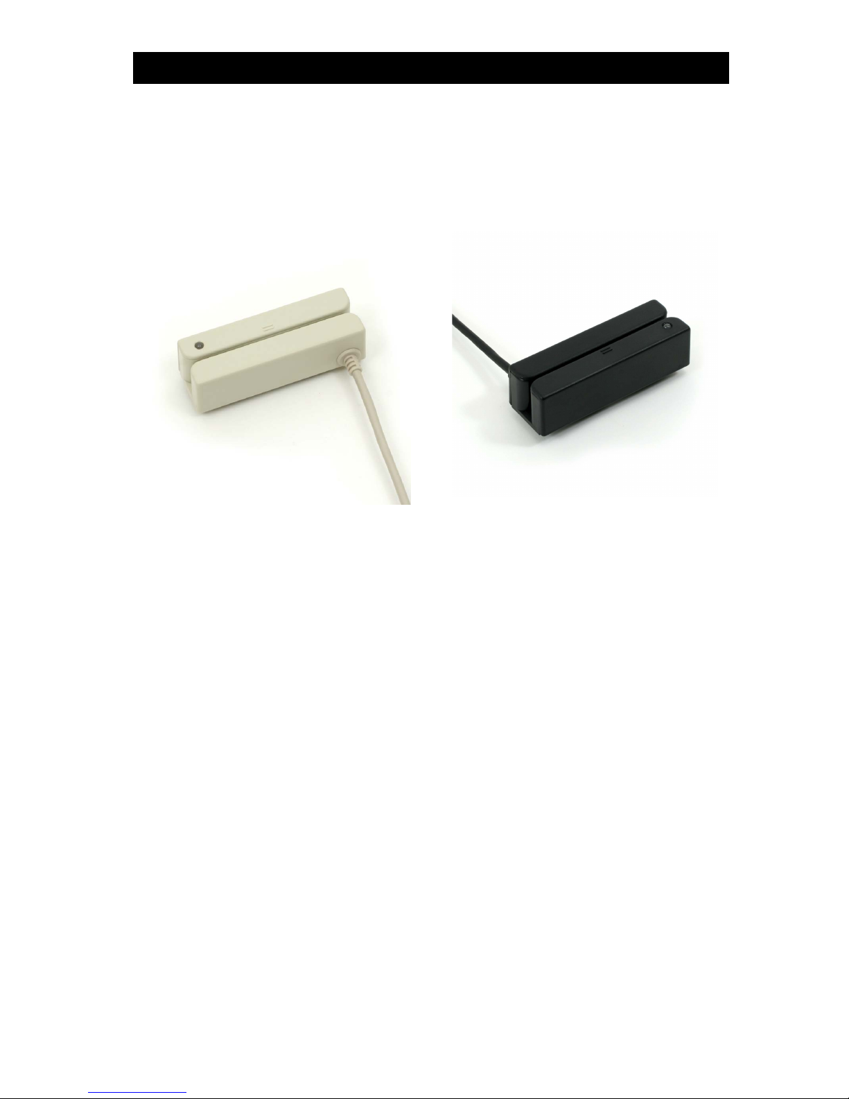
INTRODUCTION
The MS240 is a family of magnetic stripe readers specifically designed
for reading ID, credit, membershop, or other types of cards that contain
magnetic stripe data.
The MS240 comes in five interfaces: PS/2, AT, RS232, USB, and TTL
Wand.
MS240
MS241
1
Normal Operation
The MS240/241 is designed to read magnetic stripe data. If the
MS240/241 has not been altered from its factory default, it will
output the data in its original format.
The PS/2, AT, USB, and TTL readers output data as if the data had
been typed on the host computer’s keyboard, and can be viewed in
any text editor such as Notepad or Word. The RS232 reader outputs the data through the computer serial port like a modem, in
ASCII format, and thus requires a program such as HyperTerminal
to view the data.
The MS240/241 reads up to three tracks of data. Normally bank
cards utilize only the first two tracks, of which the second track
contains appropriate data for most credit card purchases. The third
track is usually present only on driver licenses.
The MS240/241 reader is compliant with ISO 7811, AAMVA, and
CA DMV formats.
Page 8

MS240/241 Manual
MS240-3
The MS240-3 AT keyboard wedge interface has a “Y” interface cable
with an AT male plug on one end and an AT female plug on the
other. The cable end with the male plug is inserted into your
computer’s keyboard port and your keyboard is plugged into the
female plug.
The MS240-3 operation should be “plug and play”. The MS240-3
has a built-in decoder that outputs the scanned data in Scancode
keyboard format. Your computer will treat your MS240-3’s input as
it would normal keyboard input.
Note: If you are using a laptop computer or a USB keyboard (ie.
you are
not using an AT keyboard), then your MS240-3 will need to
be configured as a “Keyboardless Wedge” (see “Device” in the
“Scanner Configuration Manager” section.
2
MS240-2
The RS232 (Com Port) interface should only be used when your
software is designed to accept com port input. The MS240-2 has a
built-in decoder and outputs the scanned data in ASCII Code.
MS240-2 input requires special software such as HyperTerminal
(9600 bits per second, 8 data bits, No parity, 1 stop bit, No flow
control) in order to view the output.
Note: The MS240-2 will require an optional 5V 300mA power
supply unless your computer’s com port supplies power (unlikely).
MS240A
The Undecoded (or TTL, or Wand) MS240A requires an external
decoder in order to communicate with your computer. Decoders are
built into Wedge devices and many POS (Point of Sale) keyboards,
such as the Unitech KP3700.
The MS240A cannot be configured via Scanner Configuration
Manager. Any modification of the output data must be done in the
external decoder.
Following are the the various model numbers / interfaces available
for the MS240/241 and the specifics of each.
Page 9

MS240/241 Manual
MS240-4
The USB interface is becoming popular and relatively foolproof.
Your MS240-4 uses the standard USB driver that has been included
in the Windows Operating System since Windows 98 SE.
The MS240-4 operation should be “plug and play”. The MS240-4
has a built-in decoder that outputs the scanned data in HID keyboard
format. Your computer will treat your MS240-4’s input as it would
normal keyboard input.
Note: Mac OS10 users might need to update their USB driver.
3
MS240-3PS2
The PS/2 Keyboard Wedge interface is the most popular and
straightforward. The MS240-3PS2 has a “Y” interface cable with a
PS/2 male plug on one end and a PS/2 female plug on the other.
The cable end with the male plug is inserted into your computer’s
keyboard port (not the mouse port!) and your keyboard is plugged
into the female plug.
The MS240-3PS2 operation should be “plug and play”. The MS2403PS2 has a built-in decoder that outputs the read data in Scancode
keyboard format. Your computer will treat your MS240-3PS2’s input
as it would normal keyboard input.
Note: If you are using a laptop computer or a USB keyboard (ie.
you are
not using a PS/2 keyboard), then your MS240-3PS2 will
need to be configured as a “Keyboardless Wedge” (see “Device” in
the “Scanner Configuration Manager” section.
Page 10

READER CONFIGURATION MANAGER
MS240/241 Manual
4
Start It Up
Reader Configuration Manager software is the simplest and most
foolproof way to configure your magnetic card reader settings.
The above icons, from left to right, represent download settings
(from computer to keyboard), and upload settings (from reader to
computer). The third icon opens a Test Pad (Notepad) where you
can view the actual reader output.
Above, from left to right, are the standard Windows icons for “New
Document”, “Open File”, and “Save File”.
Reader Configuration Manager saves configuration settings in .cfg
files, so you can have access to a variety of different reader configurations that you’ve set up.
To reset the reader back to factory default, click on the “New
Document” icon and download the unmanipulated setting to the
reader (see below).
After loading and starting RCMSetup.exe, the icon to the
right will appear on your desktop:
Click on the RCM icon
and the following screen
will appear:
As you can see, you are
presented with a blank
work area and a row of
icons across the top.
Following is an explanation
of each of the icons:
Page 11

The above four icons are used in the “Data Editing” feature of RCM.
From left to right thay are the “Add a Formula” icon, the “Remove a
Formula” icon, and the right-hand two are the “Move Formula” icons
that move selected formulas up or down in relation to each other.
For more information on data editing, see page 16.
Help is just a click away.
5MS240/241 Manual
Page 12

MS240/241 Manual6
First Look
Click the upload icon (see page 4) and the following pop-up screen
will appear:
Double-click on any of the
“Attributes” to edit that
attribute. This is done via
a drop-down menu.
After selecting your configuration settings, click on
the Download icon (see
page 4). The LED on the
reader will flash during the
download process. Afterwards, you may be
prompted to do an optional
“Quick Test”.
The screen to the right
appears. Click on any of
the selections under
“Current Settings” to view
its “Attributes”.
Enter the reader product
number (MS240, for example), and click “OK”.
The LED on the reader will
flash during the upload
process.
Page 13

Beeps and Delays
Beep Tone
Select a value from “None” to “High” to set the loudness of the tone,
or select “Low to High” or “High to Low” to set the characteristic of
the tone.
Default is “Medium”.
Settings
Following is a detailed discussion of each of the settings, their
attributes, and the effects each of these will have on data output
from your Unitech magnetic stripe reader.
MS240/241 Manual 7
The three attributes for “Beeps and Delays” are: “Beep Tone”,
Intercharacter Delay”, and “Interblock Delay”.
Interblock Delay
Interblock delay is the time duration that can be inserted between
one block of data and another. This function is analogous to the
time duration required between dialing a phone number’s country
code and the phone number itself. The interblock delay can be
inserted via RCM’s Data Editing function (see page 16).
Default is “10 ms”.
Intercharacter Delay
Intercharacter delay is the time duration between data characters
sent from the reader to the computer. Intercharacter delay is usually
inserted when the data flow must be slowed down to accommodate
a slower computer.
Default is “1 ms”.
Keyboard Wedge
Your Unitech reader contains a built-in data decoder that translates
raw magnetic stripe input into Keyboard Scan Code, or ASCII Code
in the case of RS232 interface readers, with the result that magnetic
stripe data exits the reader as if you had typed the text.
The four keyboard wedge parameters are listed on the following
page.
Page 14

MS240/241 Manual
8
Keyboard Wedge, continued
Use Numeric Keypad
The ASCII Code for numeric input from the keypad part of the
keyboard is different from that of the upper row of the keyboard
proper. Some accounting programs specifically require keypad
input, and for that reason, the reader decoder can output read data
as either keypad or keyboard (upper row) output.
Default is “No”
Function Code
Function Code determines how function code characters from the
magnetic stripe reader are output.
Default is “Yes”.
If Yes is selected, then read function codes will output as if
their corresponding function keys were pressed. For instance scanning an F1 label will display a “Help” pop-up box, F3 will
display a “Find” pop-up box, etc.
If No is selected, the read function codes will output special
character strings defined by Unitech for non-print character
output.
Default is “Auto Trace”.
Auto Trace automatically determines the Caps Lock key status
of your keyboard and informs the decoder accordingly.
Lower Case manually coordinates the physical state of the Caps
Lock key with the Caps Lock state of the decoder. For example,
if the Caps Lock LED of your keyboard is not lit, then “Lower
Case" should be selected.
Upper Case is the same as Lower Case (above) except that it
applies to the upper case state. If the Caps Lock LED on your
keyboard is lit, then “Upper Case” should be selected.
Caps-Lock
The Caps-Lock function determines how the Caps Lock key controls
the case of alphabetical characters. The three options below are
available:
Language
Your Unitech reader can output characters using eleven different
language sets, including:
Default is “U.S.”
Danish
U.S. English
U.K. English
French
German
Italian
Norwegian
Swedish
Spanish
Swiss
Alt Key Mode
Page 15

Receive Terminator
A user-definable Receive Terminator can be inserted at the end of
input data. Pre-defined receive terminators include:
<t>: Tab
<r>: Carriage Return
<n>: Line Feed
<d>: Any Digit
<a>: Any Letter
<*>: Interblock Delay (see page 7)
<“>: “ (quotation mark)
<dd>: Character in Hexadecimal Notation
<>>: > (greater-than sign)
<<>: < (less-than sign)
The above special characters must be bracketed by < > symbols as
shown.
Function codes (F keys, cursor up, Enter, etc.) can also be inserted
via hexadecimal code (accessable in a linked menu) and must
include surrounding brackets (<>).
Letters and numbers should be entered directly by keyboard input
without surrounding brackets (<>).
Default is “None”.
Baud Rate
Baud Rate (bits per second) refers to the speed of the data from the
MS240/241. Normally, the baud rate of the host RS232 port should
match that of the input device.
Default is “9600 Baud”.
RS232
MS240/241 Manual 9
The RS232 input characteristics of the MS240/241 (see page 2) can
be modified according to the following four parameters:
Parity
Parity is an archaic technique used to detect data transmission errors
by adding an extra bit to each character. This scheme has been
supplanted in modern communication devices by “error correction”.
Default (and the current universal standard) is “No Parity”.
Data Bit
Data bit refers to the number of bits per byte that are dedicated to
data (minus start/stop bits).
Default (and the current universal standard) is “8 Data Bits”.
Page 16

10 MS240/241 Manual
Magnetic Reader
The Magnetic Stripe Reader configuration parameters differ from
bar codes mainly in that magnetic cards adhere to only one
standard defined by ANSI and ISO/IEC, while there are over a
dozen different symbologies for bar codes.
Each magnetic stripe can contain three distinct parallel tracks, each
0.110” (2.794mm) wide. Each track’s unique characteristics are
described below.
A is defined by the card issuer and is for their exclusive use.
•
•
C-M are reserved for use by ANSI Subcommittee X3B10.
•
N-Z are available for use by individual card issuers.
B developed by the International Air Transportation Association
(IATA) contains alphanumeric information for banking and finance. The standard sequence for format B is listed below.
•
Track 1
The recording density of Track 1 is defined as 210 bits per inch.
The character configuration (encoding) is 6 bits plus 1 parity (odd)
bit, which yields 64 unique alphanumeric and symbolic characters.
The maximum information content is 79 characters, with the format
defined by the Format Code letter:
%B987654321012300^UNITECH/JOE^0512896745280?
Following is track 1 output and an explanation of the components.
% B PAN ^ CC NAME ^ DATE SC PVV DD ? LRC
normally last name, then first name, separated by a “/”
mum record length
LRC Longitudinal Redundency Check - 1 check character
? End Sentinel - 1 character - always “?” for all tracks
DD Discretionary Data - additional characters to fill out maxi-
PVV PIN Verification Value - 0 to 5 digits
SC Service Code - 3 digits -
defines transaction requirements
DATE Expiration Date - 4 digits - YYMM format
Separator - 1 character - always “^” for Track 1^
Cardholder Name - 2 to 26 alphabetical characters -NAME
Country Code - 3 digits (only for MasterCard)CC
Separator - 1 character - always “^” for Track 1^
Primary Account Number - up to 19 digitsPAN
Format Code -
1 alphabetical character - in this case, “B”
B
Start Sentinel - 1 character - always “%” for Track 1%
Page 17

11MS240/241 Manual
Track 2
The recording density of Track 2 is defined as 75 bits per inch.
The character configuration (encoding) is 4 bits plus 1 parity (odd)
bit, which yields 16 unique characters (10 numeric digits plus 6
symbolic characters :;<=>?).
The maximum information content, defined by the American Bankers
Association (ABA), is 40 characters arranged in the format below.
; PAN = CC DATE SC PVV DD ? LRC
Longitudinal Redundency Check - 1 check characterLRC
End Sentinel - 1 character - always “?” for all tracks?
Discretionary Data - additional characters to fill out
maximum record length
DD
PIN Verification Value - 0 to 5 digitsPVV
Service Code - 3 digits -
defines transaction requirements
SC
Expiration Date - 4 digits - YYMM formatDATE
Country Code - 3 digits (only for MasterCard)CC
Separator - 1 character - always “=” for Track 2=
Primary Account Number - up to 19 digitsPAN
Start Sentinel - 1 character - always “;” for Track 2;
Following is track 2 output and an explanation of the components.
;987654321012300=05121208967428?
Page 18

12 MS240/241 Manual
Track 3
The recording density of Track 3 is defined as 210 bits per inch.
The character configuration (encoding) is 4 bits plus 1 parity (odd)
bit, which yields 16 unique characters (10 numeric digits plus 6
symbolic characters :;<=>?).
The maximum information content, defined by the Thrift Industry
(THRIFT-TTS), is 107 characters arranged in the format below.
; FC PAN = CC CuC CE AA AR CB CL RC PINCP IC PANSR FSANSR
SSANSR DATE CSN CScN FSAN = SSAN = RM CCD DD ? LRC
SSANSR SSAN Service Restriction - 2 digits -
see SSAN below
Expiration Date - 4 digits - YYMM formatDATE
CSN Card Sequence Number - 1 digit
CScN Card Security Number - 9 digits
Separator - 1 character - always “=” for Track 3=
FSAN
First Subsidiary Account Number - variable number of digits
SSAN
Second Subsidiary Account Number - variable number of digits
Separator - 1 character - always “=” for Track 3=
RM Relay Marker - 1 digit
CCD Crypto Check - 1 digit
Discretionary Data - additional characters to fill out
maximum record length
DD
End Sentinel - 1 character - always “?” for all tracks?
Longitudinal Redundency Check - 1 check characterLRC
FSAN Service Restriction - 2 digits - see FSAN below
FSANSR
Cycle Length - 2 digitsCL
RC Retry Count - 1 digit - number of remaining PIN tries
PINCP PIN Control Parameters - 6 digits
IC Interchange Control - 1 digit
PANSR
PAN Service Restriction - 2 digits - describes the account
CB Cycle Begin (Validity Date) - 4 digits - YYMM format
AR Amount Remaining This Cycle - 4 digits
AA Amount Authorized Per Cycle - 4 digits
CE Currency Exponent - 1 digit
CuC Currency Code - 3 digits
Country Code - 3 digitsCC
Separator - 1 character - always “=” for Track 3=
Primary Account Number - up to 19 digitsPAN
Format Code -
2 alphabetical characters
FC
Start Sentinel - 1 character - always “;” for Track 3;
Page 19

Setting Magnetic Reader Parameters
MS240/241 Manual 13
Terminator
The Terminator is a command that follows after the bar code data.
Four different terminators can be selected here: “Enter”, “Return (on
numeric keypad)”, “Field Exit or Right Control”, or “None”. To define
a different terminator, use the “Data Editing” function (see page 16).
Default is “Enter”.
Send Start/Stop Sentinel
Each magnetic stripe track begins with a start character and ends
with a stop character (and an LRC character).
The start character for track 1 is a % (percent sign), and for tracks 2
and 3 is a ; (semi colon).
The stop character for all three tracks is a ? (question mark).
Selecting the “No” option for this parameter strips the start/stop
sentinels for eack track from the output data.
Default is “Yes”
Track Selection
Select only one, all, or any combination of the available tracks.
Selections include:
Default is “All Tracks”.
Track 3 Output
Track 2 Output
Track 1 Output
Track 2 and Track 3
Track 1 and Track 3
Track 1 and Track 2
All Tracks
Reader Configuration
Manager, shown right and
outlined in detail below,
enables the output from
the MS240/241 to be
modified to the user’s
requirements.
In a POS environment,
where only credit cards
and bank cards are read,
normally only Track 2 is
selected.
Page 20

14 MS240/241 Manual
Magnetic Reader, continued
Track 2 Account Number Only
If only track 2 is enabled (see previous page), only the account
number from track 2 and the start/stop sentinels are output.
If tracks other than track 2 are enabled, this parameter actually
outputs all the other track’s data, the account number from track 2,
and their start/stop sentinels.
Default is “No”.
Separator Character
Insert one character between each track’s output.
Pre-defined characters include:
The above special characters must be bracketed by < > symbols as
shown.
Function codes (F keys, Cursor up, Enter, etc.) can also be inserted
via hexadecimal code (accessable in a linked menu) and must
include surrounding brackets (<>).
Letters and numbers should be entered directly by keyboard input
without surrounding brackets (<>).
Default is “None”.
<t>: Tab
•
•
<n>: Line Feed
•
<d>: Any Digit (not applicable to this function)
•
<a>: Any Letter (not applicable to this function)
•
<*>: Interblock Delay (not applicable to this function)
•
<“>: “ (quotation marks)
•
<dd>: character in hexadecimal notation
•
<<>: <
•
<>>: >
Output Only When All Tracks Have Correct Data
A useful function for insuring data integrity, this function can cause
trouble when the card reader tries to read more tracks than are on the
card.
Default is “No”.
Page 21

15MS240/241 Manual
Magnetic Reader, continued
Track 2 Output Sequence
Track 2 output sequence is arranged in the same manner as the
Track 1 output sequence (above). Track 2 parameters include:
* Note that track 2 does not contain last name and first name data.
Default is “None”.
Delimiter / Text
•
All Information
•
Discretionary Data
•
Expiration Month
•
Expiration Year
•
Account Number
•
Default is “None”.
•
All Information
•
Expiration Month
•
Expiration Year
•
First Name
•
Last Name
Account Number
•
•
Discretionary Data
•
Delimiter / Text
Track 1 Output Sequence
Track 1 output sequence can be easily re-arranged to whatever
sequence the user requires. Track 1 parameters include:
Highlight a parameter (such as “Account Number”) in the
“Sources Available” area and click on the top horizontal arrow
(shown right) to move it to the “Actual Output” area. Use the
lower horizontal arrow to remove selections from the Actual
Output area.
Use the up and down arrows to move selected parameters up
or down in relation to the other parameters.
When the selected parameters are in the desired sequence,
click the “OK” button.
Page 22

MS240/241 Manual16
Data Editing
Qualifier
The Qualifier section defines the conditions that must be present for
the mag stripe data to be modified, such as which track it must be
from (Track I, Track II, etc.) or what characters (defined by a match
string) the mag stripe data must contain.
When the conditions of the Qualifier are met, the data is then modified according to the rules defined in the “Modifier”, below.
Modifier
The Modifier section contains three selections: “From Original”,
“Add New”, and “Delete”.
The Start Parameter defines the
beginning of the string of data that is
to be output. The start parameter
can either be defined by position
starting from the beginning (“From
Position”), or a specific number of
From Original extracts the desired
data from each track.
characters from the end of the string (“From Last Position”), or a
specified number of characters before or after a user-defined character string (“After Matching”).
The End Parameter defines the end of the string of data that is to
be output. Three options are available: “Number Of Characters To
Be Output”, “All Remaining”, and “After Matching”. The first two are
self-explanatory. “After Matching” defines the end as a specified
number of characters before or after a user-defined character string.
Data Editing is a powerful function that can give you tremendous
control over how data is exported from the reader.
After clicking on “Data Editing” the
data editing icons become active.
Click on the icon with the blue
circle and white plus sign.
The “Define Formula” pop-up box to
the right appears, which is divided
into two sections: “Qualifier” and
“Modifier”.
Page 23

17MS240/241 Manual
Data Editing, continued
Delete deletes existing modifier strings.
Move Up / Move Down moves the modifiers up and down
in relation to each other. The top modifier will be performed
first and each one down the list will be performed in sequence. The original data (modified or unmodified) will be
output according to its position in the modifier sequence.
Even if the original bar code data is not modified, if additional characters are to be added (see “Add New”, below) the original Start
Parameter must be defined as From Position “1” and the End
Parameter defined as “All Remaining”, otherwise, none of the
original data will be output.
Add New adds characters (printing and non-
printing) to the data output from the reader.
These characters can be added before and/or
after the actual scanned data (see “Move Up /
Move Down”, below). Pre-defined characters
include:
Characters must be bracketed by < > symbols.
Letters and numbers should be represented in hexadecimal format
(accessable in a linked menu). For instance, the lower-case letter
“t” should be entered as <74> and the numeral 5 should be entered
as <35>.
Function codes (F keys, Cursor up, Enter, etc.) can also be inserted
via hexadecimal code (accessable in a linked menu).
<>>: > (greater than)
•
<<>: < (less than)
•
<dd>: character in hexadecimal notation
•
<“>: “ (quotation marks)
•
<*>: Interblock Delay (data editing)
•
<a>: Any Letter (data editing)
•
<d>: Any Digit (data editing)
•
<n>: Line Feed
•
<r>: Carriage Return
•
<t>: Tab
•
Page 24

18 MS240/241 Manual
The “Everything Else” Formula
If a formula is entered into the Data Editing area, then all read mag
card data will be evaluated according to this formula. If the read
mag card data does not satisfy the requirements of the Qualifier
(see page 16), then no data is output. Practically speaking, the
reader has been set up to read only mag stripe data defined by
the Qualifier. You will not be able to read other mag stripes.
The answer to this problem is to end the sequence of formulas with
a formula that has no Qualifier and whose Modifier includes all the
read data (starts at position 1 and outputs “all remaining”). An
example of this can be seen as Formula 7 above.
Data Editing, continued
In the example pictured above, a series of formulas are designed to
output all the data in a mag stripe that follows a series of “0”s. For
instance, if the actual mag card data is “000045678”, the desired
output would be “45678” (the original minus all the 0s occurring at
the beginning of the string). If there are six 0s (Formula 1), then
the output starts at the seventh position. If there are five 0s
(Formula 2), then the output starts at the sixth position, etc.
If, instead, we were to place the qualifier for two 0s above (before)
the qualifier for six 0s, then the formula stipulating two 0s would
activate even if there were six 0s in the mag card data because the
qualifier would stop looking for 0s after it had found two. In this
case, all qualifiers with three or more 0s would be disregarded,
which would not be a desirable result.
Arrange Formulas
After the formulas have
been created, they must
be arranged in the optimum sequence by selecting formulas and using the
“Move Formula” icons (see
page 5). This sequence is
usually according to their
qualifier - from least likely
to occur to most likely to
occur.
Page 25

SPECIFICATIONS
MS240/241 Manual 19
INTERFACE
Connector: PS/2, RS232, TTL, USB
(see next page for pinouts)
MAGNETIC READER
Slot width: 0.055 inches (1.37mm)
Card width: 0.010 to 0.050 inches (0.254 to 1.27mm)
Swipe speed: 3 to 55 inches per second, bi-directional
Formats: ISO 7811, AAMVA, & CA DMV
MECHANICAL
Cord: 72” (183cm) straight (not coiled)
Case material: ABS plastic
Weight: 9 oz. (255 grams) with cable
Dimensions: Length - 39.37” (100mm)
Width - 1.38” (35mm)
Height - 1.30” (33mm)
ELECTRICAL
Power Supply: 5 VDC/350mA (required for RS232 version only)
Decoded - 3 tracks -
USB (keyboard) - 40mA approx.
RS232 - 40mA approx.
Keyboard - 30mA approx.
Power consumption: TTL - 1.1 mA per track while reading
Voltage: 5 Volts DC ±10%
ENVIRONMENTAL
Warranty: 1 year
Humidity: 0% to 95% RH non-condensing
-22° to 158° F (-30° to 70° C)Storage -
Temperature: Operating - 32° to 131° F (0° to 55° C)
Magnetic head life: 1,000,000 passes, minimum
Rail and cover life: 1,000,000 passes, minimum
Read rate: Less than 1 error in 100,000 bits on cards con-
forming to ISO 7811 1-5 (not operator induced)
DECODER
Configuration: Via Reader Configuration Manager software
(downloadable from www.ute.com)
Symbologies: Codabar, Code 11, Code 32, Code 39 (Standard
and Full ASCII), Code 93, Code 128, Delta Code,
EAN-8, EAN-13, Label Code IV and V, MSI Code,
Plessey Code, Standard 2 of 5, UPC-A, UPC-E
Data Editing: Almost unlimited
Page 26

PINOUTS
Pin 1 N/C
Pin 2 TXD (Transmit Data)
Pin 3 RXD (Receive Data)
Pin 4 N/C
Pin 5 GND (Ground)
Pin 6 N/C
Pin 7 CTS (Clear to Send)
Pin 8 RTS (Request to Send)
Pin 9 VCC (+5V DC Input)
RS232 Interface (DB9 female)
1
2
3
45
6
7
89
Data (Connect to PC Data)Pin 1
Reset (Connect to PC Reset)Pin 2
GroundPin 3
+5V DC InputPin 4
Clock (Connect to PC Clock)Pin 5
N/CPin 6
Keyboard Interface (6 pin mini-DIN male)
1
2
3
4
5
6
Pin 4 Ground
Pin 3 Data +
Pin 2 Data -
Pin 1 +5V DC Input
USB Interface (4 pin male)
123
4
Pin 1 N/C
Pin 2 Data
Pin 3 N/C
Pin 4 N/C
Pin 5 N/C
Pin 6 N/C
Pin 7 Ground
Pin 8 N/C
Pin 9 +5V DC Input
TTL (Wand) Interface (DB9 female - squeeze release)
1
2
3
45
6
7
89
MS240/241 Manual20
Page 27

TROUBLESHOOTING
MS240/241 Manual 21
Most problems that you might encounter with your reader can be
solved using the following procedures:
Test the scanner on other ports. Unitech products are built to
the highest standards, and a perceived reader malfunction may
actually be a malfunction in the host computer.
Test the reader on the host’s other ports if possible or, if necessary, on other systems to verify that the problem is actually in the
reader, and not in the host computer.
Reset to Factory Default. While the Reader Configuration
Manager program is active, click the “new file” icon (see page 4)
and the “download to reader” icon (see page 4) to reset your
reader back to factory default.
Caution: This procedure will erase special configurations that
you would have created. You might want to save them first.
Try reading other cards. If your reader can read other cards,
but cannot read your particular card, first check to see if other
cards from the same issuer have similar problems.
Page 28

MS240/241 Manual22
Problems and Solutions
Problem: No output from reader.
If the reader appears to read ( beeps after a swipe),
but does not output data, try reading into a word
processor application or Notepad session to see if
it’s a software problem.
Try the reader on other ports to see if it’s a computer port problem.
If your reader is connected by RS232 interface,
make sure that the correct com port is selected.
Test your reader in HyperTerminal, making sure that
“Bits per second” = 9600, “Data bits” = 8, “Parity” =
None, “Stop bits” = 1, and “Flow control” = None.
Problem: Reader Configuration Manager cannot upload or
download.
Reader Configuration Manager can currently upload
and download only in the Windows operating
system (NT excluded).
If you have a different OS, or the download function
doesn’t work, install RCM on a different Windowsbased (NT excluded) computer and try uploading/
downloading from it.
Problem: Reader reads properly, but bank cannot accept
credit card information.
At least 90% of the time, banks require only unadulterated Track II input to process a credit card
transaction.
If this does not solve the problem, have your POS
software developer swipe a working credit card
through a properly configured reader directly into a
text editor (Notepad works great). Have them X out
the sensitive info if necessary and send you the text
file. Compare this data string with yours, using the
information on page 10 in this manual to determine
what the problem might be.
Page 29

23MS240/241 Manual
Limited Hardware Warranty
The Limited Warranty terms described below are solely applicable to the Customer of Unitech Electronics (afterwards simply referred to as Unitech)
products. This warranty applies to equipment only. All consumables and
accessories are exempted.
Unitech warranties its products to be delivered free from defects in material
and workmanship, from the date of purchase. All equipment except for cables,
batteries, power supplies, and RF cards are warranted for a period of twelve
months (beginning from the month of delivery). Some products may have
longer warranties, but all products (except for cables, batteries, power supplies, and RF cards) carry at least a one year warranty. All cables, batteries,
power supplies, and RF cards external to dedicated Unitech products carry a
ninety day warranty.
During this warranty period Unitech will, at its sole discretion, replace or repair
free of charge any product(s) which, in its opinion, is/are defective. Any merchandise that is to be returned must have a valid Return Merchandise Authorization (RMA) number clearly indicated on the outside of the returned package and on the accompanying packing list. Unitech cannot be held responsible for any package returned without an RMA number. To obtain an RMA
number, please contact Unitech’s Customer Service Department or a Sale
Representative.
The Customer is responsible for packing the defective product properly, and
for the cost of shipping the defective product to Unitech. Unitech is responsible for the cost of shipping back the product which is repaired or replaced. If
any charges are borne by the Customer, the invoice for the repaired or replaced product(s) will be sent to the Customer based on the Customer’s payment terms.
In the event that the product has been modified without Unitech’s consent or
if the product failure is the result of misuse, abuse, willful neglect or misapplication, Unitech has no obligation to repair or replace the product.
Except as expressly mentioned above, the hardware and accompanying written materials (including the user’s manual) are provided “as is” without warranty of any kind, including the implied warranties of merchant ability and
fitness for a particular purpose, even if Unitech has been advised of that purpose. In no event will Unitech be liable for any direct, indirect, consequential
or incidental damages arising out of the use of or inability to use such product(s),
even if Unitech has been advised of the possibility of such damages.
WARRANTY
 Loading...