

Page 1

MR550
Stationary
Terminal
Page 2

AdventureJan
Page 3

Battery Notice
NOTICE
This unit is equipped with a Lithium-Ion battery pack,
however it may not power-on due to battery discharge
as a result of storage.
In case of the above situation, connect the unit to the
MR550’s power adapter and recharge unit for at least 16
hours to fully charge the battery.
The MR550 can operate normally for about 6 hours
(without backlight) and can backup data for 7 days
without external power.
MR550 User’s Manual
Page 4

MR550 User’s Manual
Page 5

Table of Contents
Table of Contents
Chapter 1 - First Look 1. . . . . . . . . . . . . . . . . .
1.0 - Introduction 1. . . . . . . . . . . . . . . . . . . .
1.1 - MR550 and Accessories 2. . . . . . . . . . . . . . .
1.2 - Tour of the MR550 3. . . . . . . . . . . . . . . . .
1.3 - First Steps with the MR550 . . . . . . . . . . . . . . 4
1.4 - First Operation of the MR550 5. . . . . . . . . . . . .
Chapter 2 - Specifications . . . . . . . . . . . . . . . . . 7
2.1 - CPU / Memory 7. . . . . . . . . . . . . . . . . . .
2.2 - Input / Output 7. . . . . . . . . . . . . . . . . . .
2.3 - Barcode / Symbology7. . . . . . . . . . . . . . . .
2.4 - Magnetic Stripe Reader (MSR) 7. . . . . . . . . . . .
2.5 - Interface Port . . . . . . . . . . . . . . . . . . . 8
2.6 - Power 8. . . . . . . . . . . . . . . . . . . . . .
2.7 - OS and Programming Tools 8. . . . . . . . . . . . .
2.8 - Physical and Environmental Characteristics 8. . . . . . .
2.9 - Pin Assignments . . . . . . . . . . . . . . . . . . 9
Chapter 3 - User Input 11. . . . . . . . . . . . . . . . . .
3.1 - Keypad . . . . . . . . . . . . . . . . . . . . . 11
3.2 - Software Keyboard (WinCE Keyboard) 11. . . . . . . . .
3.3 - Using Proximity, MSR, or Barcode Reader . . . . . . . . 12
Chapter 4 - Useful Programs . . . . . . . . . . . . . . . . 13
4.1 - Bar2Key . . . . . . . . . . . . . . . . . . . . . 13
4.2 - BarSetup . . . . . . . . . . . . . . . . . . . . . 14
4.3 - MSR and Proximity Reader Setup 15. . . . . . . . . . .
4.3 - HockRS232 Event (Disable ActiveSync Driver for RS232 Port) 16
MR550 User’s Manual
Page 6

MR550 User’s Manual
Page 7

Chapter 1 - First Look
Chapter 1 - First Look
1.0 - Introduction
The MR550 series is a stationary terminal. It utilizes the Windows CE®
3.0 operating system, and incorporates an integral barcode slot reader,
triple track magnetic stripe reader, Proximity reader or finger print
reader. Its PCMCIA type II slot provides wire or wireless communication
for LAN or WAN capability. It provides the user with a standard Windows-based environment for customizing and operating the device.
The MR550 is well suited for Time & Attendance, Access Control,
Loyalty program, Work-in-Process application, Price checking ,Food
court system and many other data collection applications.
1MR550 User’s Manual
Page 8

Chapter 1 - First Look
1.1 - MR550 and Accessories
After opening the box, please make sure all the following are present:
MR550
CD Manual
RS232 Cable
Getting Started
Guide
2 MR550 User’s Manual
Page 9
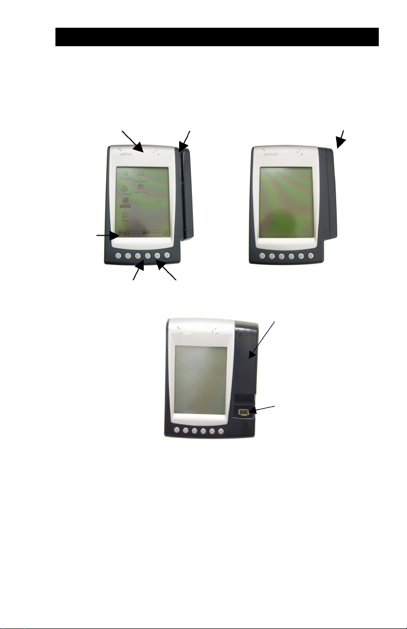
1.2 - Tour of the MR550
1.2.1 - MR550 Front
Chapter 1 - First Look
Touch
Screen
Speaker Bar Code or MSR Slot
Lock Keypad
Proximity Reader
Proximity Reader
Fingerprint Reader
3MR550 User’s Manual
Page 10

Chapter 1 - First Look
1.3 - First Steps with the MR550
NOTE: UPS battery can be used for normal operation when
there is no main power and also as a data backup battery.
Data entered should not be considered properly stored until
the built-in backup battery has been adequately charged.
Insert key into lock and turn
1.
key with anti-clockwise
direction.
Lift up back-plate to about 45°.2.
3. Ensure the UPS
battery is connected
via the white connector.
4 MR550 User’s Manual
Use a pen or screw driver to push the dip
switch to the side away from the connector (towards the bottom of the unit) to
enable the backup battery.
4. Plug the 13.5VAC Power Supply
into the MR550’s terminal
block’s AC connector on inner
side of back-plate
Plug the Power Supply into your
wall socket.
Charge the UPS battery for at
least 16 hours.
Page 11

Chapter 1 - First Look
1.4 - First Operation of the MR550
1.4.1 - Power-On the MR550
MR550 will automatically power-on when the 13.5VAC power adapter is
plugged in. The MR550 welcome screen appears, which is soon
replaced by the Windows CE screen.
1.4.2 - Calibrate the MR550
The screen to the right will automatically
appear when the unit is first powered-on
or after system reset.
The MR550 will prompt you to calibrate
the unit by tapping a sequence of screen
locations. Tap gently but firmly. When
you have completed the series of taps,
press the [ENT] key to confirm or press
the [ESC] key to cancel.
1.4.3 - Set Time Zone, Date, and Time
After Calibrating the MR550, the
“Date/ Time Properties” dialog box
will appear. Please follow below steps
to set the date and time.
5MR550 User’s Manual
Page 12

Chapter 1 - First Look
1.4.3.1 - Setting the Time Zone
Setting the correct time zone first is recommended because the system time will be automatically adjusted according to the difference between the original time zone and final time zone that you select.
Follow below steps to set it up.
Scroll down to see a list of cities.1.
Choose your location (or the nearest
2.
listed one).
Check the Daylight Saving check box, if
3.
necessary.
Tap the APPLY button.4.
1.4.3.2 - Set the Year and Month
Tap Left or Right arrow to scroll the month
Tap here
to select
the year
Tap here
to select
the month
Or directly tap location of year or month to change the year or month
setting.
1.4.3.3 - Exit Date / Time Properties
Tap OK or X (cancel) button at upper-right corner to exit.
6 MR550 User’s Manual
Page 13

Chapter 2 - Specifications
Chapter 2 - Specifications
2.1 - CPU / Memory
CPU
Flash ROM 32MB for OS and application programs
SDRAM 32MB Built-in
92 MHz 32 bits MIPS CPU. Built-in real time clock
2.2 - Input / Output
Keyboard
Audio output Speaker with software controlled volume
Display 6 inches 240 x 320 pixels portrait type
6 rubber keys, including F1~F4, ESC, and ENTER
Software Alpha-numeric keyboard
Software numeric keyboard
4 gray scale, FSTN with touch screen
LED backlight
Contrast adjustable by software hotkey
2.3 - Barcode / Symbology
Symbology Unitech’s new generation decoder chip supports:
Codabar Code 32Code 11 Code 39
Code 128Code 39 Full ASCII Code 93
EAN-8/13Delta Code EAN128
Interleaved 2 of 5 MSI / Plessy Standard 2 of 5
UPC-A/ETelpen Toshiba Code
2.4 - Magnetic Stripe Reader (MSR)
Track
Measuring tap PM50-7B (recording density 210BPI)
Tap speed 19 cm/sec (7.5 inch/sec)
Life 300,000 pass
Triple tracks
7MR550 User’s Manual
Page 14

Chapter 2 - Specifications
2.5 - Interface Port
RS232
PC card
Digital Out 2 RELAY power with 270V AC/2A
Digital In One photo-coupler input
Two RJ45 RS232C IDC type connectors:
One supports full duplex asynchronous TX, RX,
CTS, RTS, DTR, DSR communications and baud
rate up to 115.2K bps.
One supports TX, RX, CTS, RTS
PCMCIA Type II slot
2.6 - Power
Power input
UPS
External AC adapter @ 13.2VAC
1 cell Li-ion UPS battery @ 4.2V, 3000 mAH
supports 6 hours operation (without communication
and backlight) and 7 days data backup
2.7 - OS and Software Programming Tools
OS
Development
Language
Microsoft Windows CE version 3.0
Microsoft Embedded Visual Tool for VB and VC
programming
2.8 - Physical and Environmental Characteristics
Dimensions 8.46” (L) x 5.98” (W) x 1.97” (H)
215mm (L) x 152mm (W) x 50mm (H)
Approximately 2.77 lb (1.256 kg) with battery packWeight
Temperature
Drop
8 MR550 User’s Manual
Operation: 32°F ~ 122°F (0°C ~ 50°C)
Storage: -4°F ~ 158°F (-20°C ~ 70°C)
5% ~ 95% RH non-condensingHumidity
Sustains a free drop of 1.2 meters onto a concrete
floor
4KV DC contact, 8KV DC airESD protection
Page 15

Chapter 2 - Specifications
2.9 - Pin Assignments
AC Power Flex Cable to Main Board
2.9.1 - AC Power Pin Assignments
Terminal Block
Auxillary RS232
RS232
Pin Number Signal
1.
2.
3.
VAC Input 1
VAC Input 2
N/C
2.9.2 - RS232 Pin Assignments
Pin
2.
3.
Signal
DCD
2
RXD
3
TXD
4
DTR
5
GND
6
DSR
7
RTS
8
CTS1Clear To Send
Description
Data Carrier Detected
Received Data
Transmitted Data
Data Terminal Ready
Ground
Data Set Ready
Request To Send
1.
9MR550 User’s Manual
Page 16

Chapter 2 - Specifications
2.9.3 - Auxillary RS232 Pin Assignments
2.9.4 - Terminal Block
Pin
2
3
4
5
6
7
8
Pin
1
2
3
4
5
Signal
RXD
TXD
GND
RTS
CTS1Clear To Send
Function
RY2-C
RY2-NC
RY2-NO
RY1-C
RY1-NC
Description
-
Not Available
Received Data
Transmitted Data
-
Not Available
Ground
-
Not Available
Request To Send
Description
Common
Normal Close
Normal Open
Common
Normal Close
6
RY1-NO
7
DI-1
8
DI-2
9
5V
10
11
12
10 MR550 User’s Manual
5V
12V
5V Ground
Normal Open
Photo-In Cathode(-)
Photo-Out Anode(+)
Positive 5 Volts
Ground
Positive 12 Volts
Page 17

Chapter 3 - User Input
Chapter 3 - User Input
3.1 - Keypad
The MR550 keypad contains 6 rubber keys, including F1~F4, ESC, and
ENTER key. Please refer to the picture below.
Clock-In
F1
[F1]~[F4] Standard WinCE Function Keys
[ESC]
[BS]
Break-OutF2Break-In
F3
The Escape key performs the same function as tapping the
CANCEL or X icon on the touch screen
The Back-Space key is used to erase previously input
characters
Clock-Out
F4
Escape Enter
3.2 - Software Keyboard (WinCE Keyboard)
Because the MR550’s rubber keypad allows input of numeric characters
only, Windows CE Software provides a touch screen keyboard for input
of other characters. The Windows-based keyboard replicates the layout
of a standard PC keyboard.
3.2.1 - Open WinCE Keyboard:
Open the Windows CE keyboard by tapping the “keyboard” icon on the
task bar. (Refer to the picture below).
Double-tap here
3.1 Software Keyboard (Window
11MR550 User’s Manual
Page 18

Chapter 3 - User Input
3.2.2 - Keying-in Characters:
After double tapping the “keyboard”
icon, the Windows CE keyboard
pops-up. Character input is the same
as a standard PC. Simply tap the onscreen button corresponding to the
character you want to input.
3.2.3 - International Character
Support:
Tap the [áü] button to switch from the
standard English keyboard to the
European keyboard.
3.2.4 - Closing the Keyboard:
Double tap the keyboard icon to
close Windows CE keyboard.
Title bar
3.3 - Using Proximity, MSR, or Barcode Reader
The MR550 has an integrated Proximity, MSR or Barcode reader, connected to Unitech’s new generation decoder chip, which can read all major
barcode labels, magnetic stripe cards, or 125KHz EM proximity readers
with excellent performance.
The MR550 also has a built-in
TTY.EXE program that allows the
user to test reader’s data.
TTY.EXE is located in directory
\WINDOWS, and is also accessible
by short-cut via Programs located
in the Start menu.
12 MR550 User’s Manual
Page 19
Chapter 4 - Useful Programs
Chapter 4 - Useful Programs
4.1 - Bar2Key
In the MR550, the built-in scanner, magnetic stripe reader or proximity
are connected to an advanced decoder chip, and this chip is connected
to COM3 port. Application programs should call Unitech’s scanner DLL
library (Please refer to MR550 programming manual for detailed
function of DLL library). Oftentimes it is not easy to get read data into
application programs, especially if the application is provided by a third
party, and users are not allowed to modify the source program.
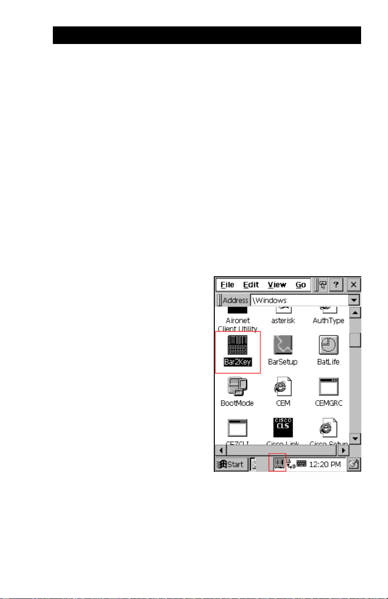
“Bar2Key.exe” is an useful tool to get scanned/swiped data into any
application program. While Bar2Key is running, all scanned/swiped
data goes into the standard keyboard input buffer. Scanned/swiped data
will be treated as normal keyboard input. Thus, any application program can input scanned/swiped data, just as if it were input by keyboard.
Bar2Key.EXE is located in the Windows folder. After executing the program, a Barcode icon will appear on
the taskbar. Press scanner trigger
key (or swipe) as you normally would
to scan a barcode label.
For exiting Bar2Key, double tap the
Barcode icon on the taskbar and then
tap the Exit button.
For detail barcode symbology and
MSR settings, please refer to the
next 2 sections.
13MR550 User’s Manual
Page 20

Chapter 4 - Useful Programs
g
4.2 - BarSetup
BarSetup provides the ability to change
default symbologies for different applications, put delimiter characters behind
scanning data, and save settings to individual profiles.
BarSetup can be found at
\Windows\BarSetup.exe. After
starting the program two buttons:
“Barcode Symbologies” and
“Delimeter” will be displayed.
Customization symbologies for each symbology include:
Symbology
Code 39
I 2 of 5
S25/Toshiba
Code 32
Telpen
EAN128
Code128
MSI/Plessy
Code93
Code11
Codabar
Label Code
UPC-A
UPC-E
EAN13
EAN8
Supplement
Delta Code
Delimeter: None, Tab, CR, LF, CRLF, Comma
Enable/
Disable
Yes Yes Calculate Check digit
Send
Maxi/
Check
Mini.
Digit
Yes Yes Yes Full ASCII
Yes Yes Yes Send Start/Stop character
Yes Yes Yes Fix length
Yes Send Leading code
Yes Character Set
Yes
Yes Yes
Yes Yes Yes Check digit module
Yes Yes
Yes Yes Yes One/Two check digit
Yes Yes Yes Send Start/Stop character
Yes Yes
Yes Yes Yes
Yes Yes Yes Zero expansion on
Yes Yes Yes Enable Bookland
Yes Yes Yes
Supplement 2
Length
Send
Other
Leadin
Digit
Send Start/Stop character
Fix length
Send Tailing code
CLSI format on
Enable NSC
Supplement 5
Space separator inserted
Transmit if present/
Must be present
14 MR550 User’s Manual
Page 21

Chapter 4 - Useful Programs
Individual settings can be written to
a file (*.b2k) and then dynamically
loaded for different applications.
Otherwise, the default settings can
be used.
4.3 - MSR and Proximity Reader Setup
The MSR’s track function and
delimiter must be individually
enabled/disabled for different
applications.
MSRSetup provides the ability to
change default settings, put delimiter characters behind track data,
and either save settings to individual
profiles or load profiles.
User can run this program from
\Windows\MRRSetup.exe. Displayed will be one button: “MSR
Delimiter”.
The Proximity reader is connected
as an MSR track 2 reader by
configuring it via the track 2 setting.
15MR550 User’s Manual
Page 22
Chapter 4 - Useful Programs
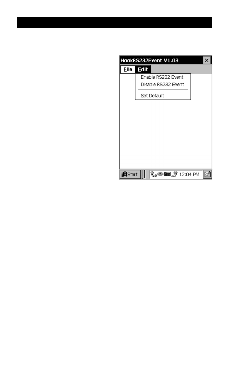
4.3 - HockRS232 Event (Disable ActiveSync Driver for RS232 Port)
Normally, the MR550’s RS232 port
is set as the default communication
port with the Host PC via
ActiveSync. The MR550 will
automatically activate the
ActiveSync driver and try to connect
to the Host PC if the user directly
connects the RS232 cable without
running any programs. Sometimes,
however, the ActiveSync popup
window becomes inconvenient.
“Hock RS232 Event.exe” is a useful
tool to enable/disable ActiveSync
driver. This program can be run
from \Windows\HockRS232
Event.exe. Pull down the “Edit”
menu to select the proper item.
16 MR550 User’s Manual
Page 23
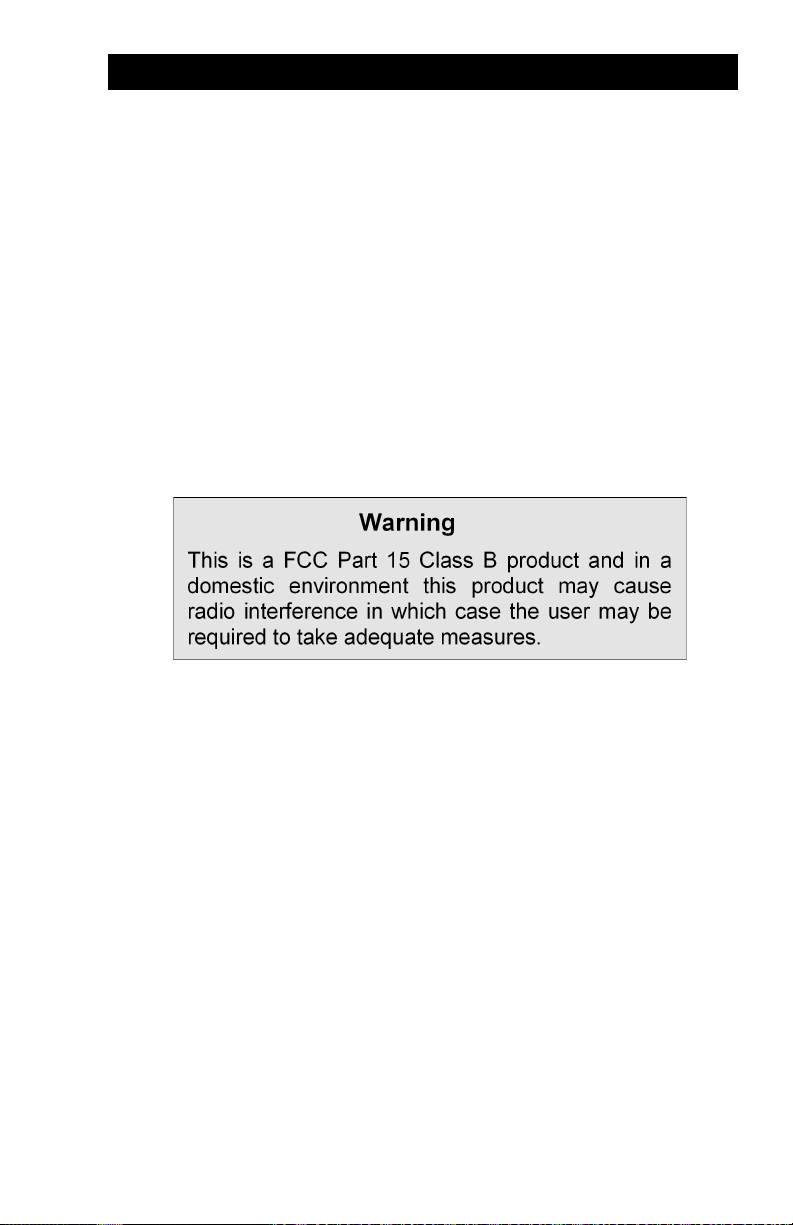
FCC Warning
17MR550 User’s Manual
 Loading...