

Unitary products group C*ED060A Series, C*ED090A Series, C*ED120A Series, C*ED180A Series Installation Instruction

INSTALLATION
SINGLE PACKAGE
INSTRUCTION
TABLE OF CONTENTS
GENERAL . . . . . . . . . . . . . . . . . . . . . . . . . . . . . . . . . 3
CAUTIONS, NOTES AND WARNINGS . . . . . . . . . . 3
INSPECTION . . . . . . . . . . . . . . . . . . . . . . . . . . . . . . . 3
LIMITATIONS . . . . . . . . . . . . . . . . . . . . . . . . . . . . . . 3
INSTALLATION . . . . . . . . . . . . . . . . . . . . . . . . . . . . 4
OPERATION . . . . . . . . . . . . . . . . . . . . . . . . . . . . . . 23
A Complete Table of Contents on Following Page
WATER COOLED
AIR CONDITIONERS
EMBASSSY SERIES
MODELS C*ED060A, 090A, 120A, & 180A
SAVE THIS MANUAL
035-16734-000 REV A (799) Form 560.20-N1Y

560.20-N1Y 035-16734-000
y
TABLE OF CONTENTS
GENERAL . . . . . . . . . . . . . . . . . . . . . . . . . . . . . . . . . 3
CAUTIONS, NOTES AND WARNINGS . . . . . . . . . . 3
INSPECTION . . . . . . . . . . . . . . . . . . . . . . . . . . . . . . . 3
LIMITATIONS . . . . . . . . . . . . . . . . . . . . . . . . . . . . . . 3
INSTALLATION . . . . . . . . . . . . . . . . . . . . . . . . . . . . 4
ACCESSORIES . . . . . . . . . . . . . . . . . . . . . . . . . . . . . . . .4
LOCATION . . . . . . . . . . . . . . . . . . . . . . . . . . . . . . . . . . . . 5
FOUNDATION . . . . . . . . . . . . . . . . . . . . . . . . . . . . . . . . .5
CLEARANCE . . . . . . . . . . . . . . . . . . . . . . . . . . . . . . . . . .5
RIGGING . . . . . . . . . . . . . . . . . . . . . . . . . . . . . . . . . . . . . .5
UNCRATNG . . . . . . . . . . . . . . . . . . . . . . . . . . . . . . . . . . .5
SHIPPING BOLTS . . . . . . . . . . . . . . . . . . . . . . . . . . . . .15
BLOWER ARRANGEMENTS . . . . . . . . . . . . . . . . . . . . . 15
SUPPLY AIR BLOWER ADJUSTMENT . . . . . . . . . . . . .15
DUCT CONNECTIONS . . . . . . . . . . . . . . . . . . . . . . . . . . 18
SUPPLY AIR DUCTS . . . . . . . . . . . . . . . . . . . . . . . . . . . 19
RETURN AIR DUCT FLANGE . . . . . . . . . . . . . . . . . . . . 19
INSULATION . . . . . . . . . . . . . . . . . . . . . . . . . . . . . . . . . .19
CONDENSER WATER PIPING . . . . . . . . . . . . . . . . . . .19
PRECAUTIONS AGAINST FREEZING . . . . . . . . . . . . . . . . . .19
DRAIN CONNECTIONS . . . . . . . . . . . . . . . . . . . . . . . . . . . . .20
REFRIGERATION SYSTEM . . . . . . . . . . . . . . . . . . . . . .20
WIRING . . . . . . . . . . . . . . . . . . . . . . . . . . . . . . . . . . . . . . 20
POWER WIRING . . . . . . . . . . . . . . . . . . . . . . . . . . . . . . . . . . .20
LOW VOLTAGE WIRING . . . . . . . . . . . . . . . . . . . . . . . . . . . .20
ACCESSORY WIRING . . . . . . . . . . . . . . . . . . . . . . . . . . . . . .21
WATER REGULATING VALVES . . . . . . . . . . . . . . . . . .21
COOLING TOWER . . . . . . . . . . . . . . . . . . . . . . . . . . . . .21
16 CTRL (LOW VOLT) FIELD WIRING DIA. . . . . . 22
17 COOLING TOWER WATER PIPING . . . . . . . . . 24
18 UNIT CONTROL ON WATER FLOW . . . . . . . . 24
19 ALT UNIT CONTROL ON WATER FLOW . . . . 24
LIST OF TABLES
1 APPLICATION DATA . . . . . . . . . . . . . . . . . . . . . 4
2 OPERATING AND SHIPPING WEIGHT . . . . . . . 5
3 PHYSICAL DATA . . . . . . . . . . . . . . . . . . . . . . . . 6
4 COOLING CAPACITY 80°F TO 90°F . . . . . . . . . 7
5 COOLING CAPACITY 100°F TO 110°F . . . . . . . 8
6 CORRECTION FACTORS ALL MODELS . . . . . 9
7 CONDENSER WATER PRESSURE DROP . . . . 9
8 SUPPLY AIR BLOWER PERFORMANCE . . . . 10
9 MINIMUM CLEARANCES CED060 . . . . . . . . . . 14
10 MINIMUM CLEARANCES CED090 & 120 . . . . 14
11 MINIMUM CLEARANCES CED180 . . . . . . . . . . 14
12 SPLY AIR BLWR MOTOR PULLEY ADJ . . . . . 16
13 TUBE HOLE LOCATIONS . . . . . . . . . . . . . . . . 17
14 CFM RATINGS . . . . . . . . . . . . . . . . . . . . . . . . . 17
15 BLOWER MOTOR DRIVE DATA . . . . . . . . . . . 18
16 WATER CONNECTION SIZING . . . . . . . . . . . . 19
17 ELECTRICAL DATA . . . . . . . . . . . . . . . . . . . . . 23
OPERATION . . . . . . . . . . . . . . . . . . . . . . . . . . . . . . 23
ADJUSTING WATER REGULATING VALVE . . . . . . . . .24
LIST OF FIGURES
1 PRODUCT NOMENCLATURE . . . . . . . . . . . . . . 3
2 UNIT DIMENSIONS - CED060 . . . . . . . . . . . . . 11
3 UNIT DIMENSIONS - CED090 & 120 . . . . . . . . 12
4 UNIT DIMENSIONS - CED180 . . . . . . . . . . . . . 13
5 BLOWER ARRANGE CED060, 090 & 120 . . . . 15
6 BLOWER ARRANGE CED180 #1 . . . . . . . . . . . 15
7 BLOWER ARRANGE CED180 #2, #3, & #4 . . . 15
8 TYPICAL MOTOR MOUNTING ASSEMBLY . . 16
9 PROBE LOCATIONS . . . . . . . . . . . . . . . . . . . . 17
10 CFM CURVE . . . . . . . . . . . . . . . . . . . . . . . . . . . 17
11 SUPPLY AIR DUCT CONNECTION . . . . . . . . . 18
12 COILS AND WATER CONNECTIONS . . . . . . . 19
13 RECOMMENDED DRAIN PIPING . . . . . . . . . . . 20
14 ELECTRICAL CONTROL BOX . . . . . . . . . . . . . 21
15 PS FIELD WIRING DIAGRAM . . . . . . . . . . . . . . 22
2 Unitar
Products Group

035-16734-000 560.20-N1Y
y
g
y
y
g
y
y
y
y
y
y
y
y
g
g
g
y
g
g
y
y
g
g
y
g
g
g
g
y
y
C
2
PRODUCT CATEG ORY
C = Single P ackage A ir
C o n d ito n in g U n it
(W a te r C o o le d )
PRODUCT GENERATION
2 = 2nd G eneration
PRODUCT IDENTIFIER
E D = E m bassy Factory
A s s e m b le d U n it w ith
B lo w e r M o to r and D rive
NOM INAL COOLING CAPACITY
FIGURE 1 : PRODUCT NOMENCLATURE
GENERAL
These C2ED Embassy units are water-cooled, single pack-
e air conditioners designed for vertical application and
a
indoor installation onl
conditioned space or in a utilit
. The unit may be installed within the
room.
DE
Installer should pay particular attention to the words: NOTE,
CAUTION and WARNING. Notes
make the installation easier. Cautions
equipment dama
that personal injur
the installation proced ure is not handl ed prop erl
9 0 A
0
060 = 5 Tons
090 = 7-1/2 Tons
120 = 10 Tons
180 = 15 Tons
2 5
INSTALLED HEAT
A = N o t A p p lic a b le
e. Warnings are given to alert the installer
and/or equipment damage may result if
VOLTAG E C O DE
06-208/230-1-60
25-208/230-3-60
46-460-3-60
FAC TO RY
are intended to clarify or
are given to prev ent
.
Models ED060, ED090 and 120 are desi
flow onl
The ED180 is factor
blower section ma
Units ma
return, with suppl
or a combination of these items.
Units are complet el
wired, tested and read
mounted in the blower se cti on. Units less motor and drive or
with alternate motors and drives are not available.
The units require electrical power, duct connections or plenum, condenser wa ter p ipi n
tial support at the point of installation.
Wate r pi pi n
made from either side of unit. Low volta
side onl
Drain connections a r e ma de on the ri
except the ED180, which can be made form either side.
and can not be field converted to horizontal airflow.
assembled f or vertical air flow, but the
be field converted for horizontal airflow.
be installed either with ductwork on supply and
air plenum and return air grille accessor
factory assembled, refr igerant ch arged,
for installation. Motor and drive are
, condensate drai n a nd s ub sta n-
connections an d power wiring entrance can be
.
ned for vertical air-
e entrance on right
ht side only for all units
CAUTIONS, NOTES AND WARNINGS
INSPECTION
Immediately upon receiv ing the unit, it should be inspected
for possible da ma
should be noted on the carrier’s frei
request for inspection b
in writin
.
e during transit. If damage is evident, it
ht bill. A separate
the carrier’s agent should be ma de
LIMITATIONS
1. Units are not suitable for brackish or salt water.
2. Refer to Table 1 for recomm en ded c ond ens er w ater flo w
rate and water temperature rise for coolin
cation.
3. Excessively high GPM and low water temperature may
result in coil freeze up.
4. A water-re
applications; it should be adjusted to maintain a head
pressure of 220 psi
approximatel
5. Excessivel
result in H.P. Cutout trip, 325 PSI.
6. Units are not intended for outdoor installation.
ulating valve is recommended for city water
and a water temperature rise of
20°F.
low GPM and high water temperature may
tower appli-
Products Group 3
Unitar

560.20-N1Y 035-16734-000
y
g
y
g sy
g
g
g
y
g
7. These units should be installed in accordance with:
a. Re
b. Standards for air conditionin
ulations of National Board of Fire Underwriters,
local utilit
or other authorities having jurisdiction.
stems, National Fire
Association Pamphlet # 90.
TABLE 1: APPLICATION DATA
LIMITATION
208/230-1-60 187 252
P
OWER SUPPLY
S
UPPLY AIR
A
IR TEMPERATURE ENTERING
C
OOLING COIL
C
ONDENSER WATER
C
ONDENSER WATER-SIDE WORKING PRESSURE
, V
, CFM
°F
OLTS
, GPM
208/230-3-60 187 252
460-3-60 432 504
C2ED060 1600 2400
C2ED090 2400 3600
C2ED120 3200 4800
C2ED180 4800 7200
Wet Bulb 57 72
Dry Bulb 65 95
C2ED060 4 20
C2ED090 6 30
C2ED120 8 40
C2ED180 12 60
, PSIG
c. National Warm Air Heatin
and Air Conditionin
Association Manuals, which ever is applicable.
d. Wirin
must conform to provisions of National Electrical Code (NFPE Pamphlet # 70) and local ordinances.
MINIMUM
2
20
1
MAXIMUM
150
1
3
L
EAVING CONDENSER WATER TEMPERATURE
1.
Utilization Range “A” in accordance with ARI Standard 110.
2.
The water pressure must be great enough to overcome the pressure drop of the condenser and the condenser water piping.
3.
Although the water side is only leak tested for 150psig, the maximum water-side working pressure of the condenser is 450 psig.
Class 150 fittings in the unit’s condenser water piping are good for 300 psig. For 300 psig applications, a sealing material (Locktite or equivalent) must be applied to all threaded connections to assure a leak-tight installation. The water regulating valve accessories are limited to a maximum 150 psig.
4.
The limitation for entering condenser water temperature will vary with condenser water GPM.
INSTALLATION
4
, °F
ACCESSORIES
60 115
Refer to the following instructions for installation of accessories:
• Form 550.13-N10.1U Electric Heat
THIS PRODUCT MUST BE INSTALLED IN
STRICT COMPLIANCE WITH THE ENCLOSED
INSTALLATION INSTRUCTIONS AND ANY
APPLICABLE LOCAL, STATE, AND NATIONAL
CODES INCLUDING BUT NOT LIMITED TO,
• Form 550.13-N10.2U Suppl
• Form 550.13-N10.3U Return Air Grille
• Form 550.12-N10.7U Hot Water Coil and Non-Freeze
Steam Coil
• Form 560.20-N1.5 W ate r Re
Air Plenum
ulating Valve
BUILDING, ELECTRICAL AND MECHANICAL
CODES.
4 Unitar
Products Group

035-16734-000 560.20-N1Y
y
y
g
g
g
g
g
y
g
g
ging
g
g
y
g
g
g
g
g
g
y
g
g
g
g
g
g
g
y
g
y
g
g
LOCATION
1. Units may be located in the conditioned space or in an
adjacent room. Units ma
must be protected from freezin
2. Units should be installed in an area offerin
power and control wir in
densate trap and pi pin
if required, outdoor air duct if required, and supply
in
not be located outdoors, and
.
proper
, condenser water piping, con-
, overflow if required, heating pip-
and return air.
FOR WINTER SHUTDOWN, RESIDUAL WATER
MUST BE BLOWN FROM THE CONDENSER IF
THE UNIT IS LOCATED IN AN AREA WHERE
THE AMBIENT TEMPERATURE MAY DROP
BELOW 32°F OR IF THE UNIT HAS AN OUTDOOR AIR INTAKE.
3. Supply air may be ducted or distributed with a plenum.
Return air ma
an inlet
be ducted, unducted or returned through
rille. If the unit is to have an outdoor air intake,
it should be located near and outside wall.
Units should be located for ease of service, with adequate
clearance for compressor access, front and ri
drive access, chan
filters, and heating coil service if
required. Refer to respective unit dimension detail (Fi
ht side, fan
ure 2,
3, and 4) for required clearances.
FOUNDATION
1. Units may be placed on the floor or b e elev ated o n a su itable platform.
2. No special foundation or isolation is required for most
applications.
a. Unit incorporates adequate isolation to eliminate
fan, compressor, and condensin
Flexible duct is also recommended.
b. It is not necessar
in
structure.
to bolt unit to the floor or support-
c. Floor or platform must be capable of supportin
operatin
wei
3. For installations requirin
followin
weight of the unit. See Table 2 for unit
hts.
extreme quiet operation, the
precautions should be considered:
a. Locate unit outside the conditioned space.
b. Suppl
and return air ducts should be used, connected to the unit with asbestos cloth collars, and
lined with sound absorbing material.
section vibration.
the
c. Support the unit on a separate floor structure form
that of the conditioned space.
d. Place a non-deteriorating sound isolation pad under
the entire unit base.
CLEARANCE
Clearance must be provided for:
1. Air intake and discharge – with or without ductwork.
2. Condenser water pipin
and connections.
3. Electrical power conne cti on s.
4. Heatin
coil piping and connections, if required.
5. Trapped condensate drain connection.
6. Maintenance and service access. Recommended minimum clearances for units are shown on the unit dimension drawin
are based on standard arran
standard arran
’s Figures 2, 3, and 4. These clearances
ements of units. For non-
ements, allow clearan ce s th at are in line
with the recommended minimum values shown.
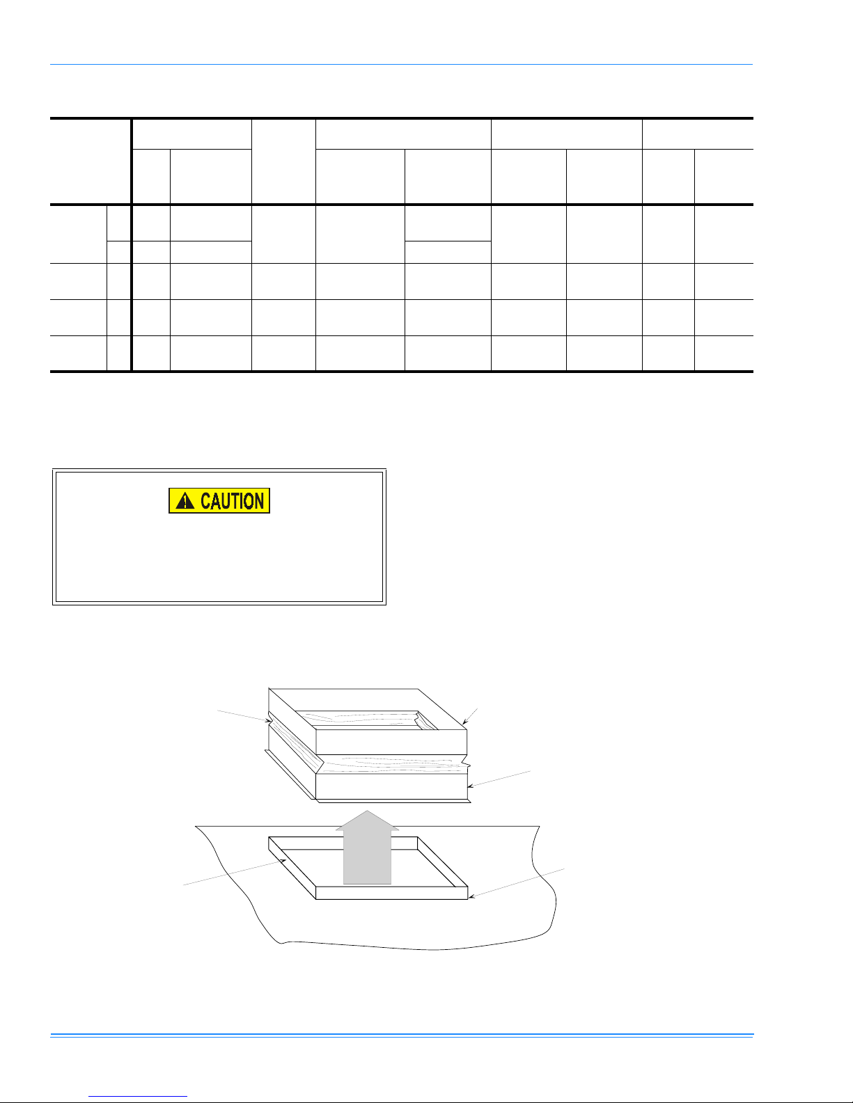
RIGGING
1. Lift with slings under the unit.
2. Use spreader bars across the top of the unit to prevent
crushin
3. Avoid possible surface dama
the unit frame and panels.
e by NOT removing the
carton or the skids un til the unit is at or near its final location and soon to be installed.
TABLE 2: OPERATING AND SHIPPING WEIGHT
(LBS.)
MODEL C2ED 060 090 120 180
S
HIPPING WEIGHT
O
PERATING WEIGHT
452 755 809 1115
402 690 744 1040
UNCRATNG
Keep the units in their carton until moved close to point of
installation. Units are mounted on skids and should be
“trucked” to location in a vertical position. Under no circumstances should the
1. Remove the shippin
2. Remove skid from under the unit.
3. Remove front access panel from condenser section.
This is necessar
denser water pipin
blocks.
pin
be “walked” on the corners of the crate.
carton.
for access to the electrical box, con-
and the removal of compre ssor s hip-
Products Group 5
Unitar

560.20-N1Y 035-16734-000
y
TABLE 3: PHYSICAL DATA
DESCRIPTION
Quantity Per Unit
C
OMPRESSOR
(F
ULLY HERMETIC
3-3/4 ton - 2 - 5-Ton 1 - 2 1
10-Ton - - Rows Deep x Rows Wide 3 x 24 3 x 24 3 x 32 4 x 26
Finned Length - inches 30 46 46 54.5
E
VAPORATOR COIL
Face Area - square feet 5.0 7.7 10.2 12.4
Tube (Copper) OD - inches 3/8 3/8 3/8 1/2
Fins (Aluminum) per inch 13 13 13 12
C
ENTRIFUGAL BLOWER
(F
ORWARD CURVE
2
M
OTORS
F
ILTERS
(T
HROWAWAY
)
)
Diameter x Width - inches 10 x 10 15 x 15 15 x 15 18 x 18
Nominal HP Rating
Quantity per Unit
Face Area - square feet 5.6 11.1 11.1 16.7
Quantity Per Unit
C
ONDENSER
(W
ATER COOLED
)
3-3/4 Ton - 2 - 5 Ton 1 - 2 3
Refrigerant-22, lbs. - oz.
O
PERATING CHARGE
System - 1 5-1 4-9 5-14
System - 2 - 4-9 5-14 5-4
1.
The 10-Ton system is wired for first stage operation.
2.
The refer to Table 15 for additional blower motor and drive data.
UNIT MODEL
CED060 CED090 CED120 CED180
3/4
(1@460-3-60)
1-1/2 2 3
16” x 25” x 1” 2 4 4 20” x 20” x 1” - - - 6
12-0
1
1
2
6 Unitar
Products Group

035-16734-000 560.20-N1Y
y
g
TABLE 4: COOLING CAPACITY 80°F TO 90°F
AIR ENTERING
MODEL
CED
060
(1 Phase)
060
(3 Phase)
090
120
180
1.
These capacities are gross ratings. For net capacities, determine the Kw requirements of the supply air blower motor per T able 8.
Convert kW to MBH per the following equation and deduct this equivalent heat from the gross cooling ratings.
BLOWER MOTOR kW x (3.415 MBH / kW) = Blower Motor Heat (MBH)
2.
Compressor kW only. For total unit kW, add the kW requirement of the supply air blower per Table 8.
COOLING COIL TOTAL
TEMP. °F
CFM
86 72
2000
2000
3000
3000
6000
80 67 63 43 4.3 10.4 59 42 4.6 10.0
56 41 57 41 4.2 9.6 54 40 4.5 9.3
68 57 52 40 4.1 8.8 49 39 4.4 8.6
86 72
80 67 63 43 4.1 10.3 59 42 4.4 9.9
74 62 57 41 4.0 9.5 54 40 4.3 9.2
68 57 52 40 3.9 8.7 49 39 4.2 8.5
86 72
80 67 94 65 6.0 10.2 89 63 6.4 9.9
74 62 86 62 5.8 9.4 81 61 6.2 9.1
68 57 77 60 5.7 8.6 73 59 6.1 8.4
86 72
80 67 128 90 8.2 10.5 121 87 8.8 10. 1
74 62 118 87 8.0 9.7 110 84 8.6 9.4
68 57 107 84 7.8 8.9 100 81 8.4 8.6
86 72
80 67 195 139 13.1 10.6 187 135 13.7 10.4
74 62 175 133 12.8 8.7 168 130 13.5 9.5
68 57 154 127 12.6 8.8 149 125 13.3 8.6
COND.
WATER
GPM
15
15
22.5
30
45
1
CONDENSER WATER TEMPERATURE, °F
80 90
TOT.
MBH
69 45 4.4 11.2 65 44 4.7 10.8
69 45 4.2 11.1 65 44 4.5 10.7
102 68 6.2 11.0 97 66 6.6 10.6
139 93 8.4 11.2 132 90 9.0 10.8
211 146 13.4 11.4 203 140 14.0 11.2
SENS.
MBH
Kw
2
WATER
RANGE
°F
TOT.
MBH
SENS.
MBH
Kw
2
WATER
RANGE
°FDB WB
Nominal Ratin
Products Group 7
Unitar

560.20-N1Y 035-16734-000
y
g
TABLE 5: COOLING CAPACITY 100°F TO 110°F
AIR ENTERING
MODEL
CED
060
(1 Phase)
060
(3 Phase)
090
120
180
1.
These capacities are gross ratings. For net capacities, determine the Kw requirements of the supply air blower motor per Table 8.
Convert kW to MBH per the following equation and deduct this equivalent heat from the gross cooling ratings.
BLOWER MOTOR kW x (3.415 MBH / kW) = Blower Motor Heat (MBH)
2.
Compressor kW only. For total unit kW, add the kW requirement of the supply air blower per Table 8.
COOLING COIL TOTAL
TEMP. °F
CFM
86 72
2000
2000
3000
3000
6000
80 67 56 41 4.9 9.7 53 40 5.2 9.4
56 41 51 39 4.8 9.0 48 38 5.1 8.7
68 57 46 38 4.7 8.3 43 37 5.0 8.0
86 72
80 67 56 41 4.7 9.6 53 40 5.0 9.3
74 62 51 39 4.6 8.9 48 38 4.9 8.6
68 57 46 38 4.5 8.2 43 37 4.8 7.9
86 72
80 67 84 61 6.8 9.5 78 58 7.3 9.1
74 62 76 59 6.6 8.8 71 56 7.1 8.4
68 57 68 57 6.5 8.1 64 55 7.0 7.8
86 72
80 67 114 84 9.4 9.7 106 81 10.0 9.3
74 62 103 81 9.2 9.0 96 78 9.8 8.6
68 57 93 78 9.0 8.3 86 75 9.6 7.9
86 72
80 67 175 130 14.4 9.9 158 125 15.1 9.3
74 62 158 126 14.2 9.1 145 122 14.8 8.7
68 57 141 122 14.0 8.4 132 119 14.6 8.1
COND.
WATER
GPM
15
15
22.5
30
45
1
CONDENSER WATER TEMPERATURE, °F
100 110
TOT.
MBH
62 43 5.0 10.5 58 42 5.3 10.1
62 43 4.8 10.4 58 42 5.1 10.0
91 63 7.0 10.2 85 60 7.5 9.8
124 87 9.6 10.4 116 85 10.3 10.0
188 134 14.7 10.6 170 128 15.4 9.9
SENS.
MBH
Kw
2
WATER
RANGE
°F
TOT.
MBH
SENS.
MBH
Kw
2
WATER
RANGE
°FDB WB
Nominal Ratin
8 Unitar
Products Group

035-16734-000 560.20-N1Y
y
TABLE 6: CORRECTION FACTORS - ALL MODELS
RATING
Total Capacity
Sensible Capacity
Compressor kW
80 90 100 110 120 50 75 100 125 150
0.95 0.98 1. 00 1.01 1.02 0.90 0.96 1.00 1.03 1.05
0.85 0.94 1. 00 1.04 1.07 0.95 0.98 1.00 1.01 1.02
0.97 0.99 1. 00 1.01 1.02 1.10 1.04 1.00 0.97 0.95
% CFM % GPM
TABLE 7: CONDENSER WATER PRESSURE DROP
MODEL
CED060
CED090
CONDENSER
WATE R GPM
10
15
20
15
22.5
30
PRESSURE
DROP PSI
2.0
4.4
8.0
2.4
3.0
4.2
MODEL
CED120
CED180
CONDENSER
WATER GPM
20
30
40
30
45
60
PRESSURE
DROP PSI
2.0
4.4
8.0
2.0
4.4
8.0
Products Group 9
Unitar

560.20-N1Y 035-16734-000
y
y
y
TABLE 8: SUPPLY AIR BLOWER PERFORMANCE
RPM
810
900
1000
1100
1110
655
700
800
880
SP
2
BHP
3
kW
1600
0.45 0.39 0.35
0.64 0.48 0.43
0.87 0.58 0.53
1.12 0.69 0.64
1.15 0.70 0.65
2400
0.49 0.70 0.66
0.60 0.77 0.73
0.92 0.97 0.90
1.18 1. 11 1.04
SP
0.32
0.53
0.77
1.03
1.06
0.41
0.53
0.85
1.11
2
BHP
3
kW
1800
0.46 0.42 0.18 0.53 0.49 0.02 0.61 0.56 - - -
0.56 0.51 0.40 0.64 0.59 0.25 0.73 0.68 0.10 0.82 0.77
0.67 0.62 0.65 0.76 0.71 0.51 0.86 0.81 0.37 0.91 0.90
0.78 0.73 0.92 0.89 0.83 0.79 1.00 0.94 0.66 1.13 1.04
0.79 0.74 0.95 0.90 0.84 0.82 1.02 0.95 - - -
2700
0.78 0.72 0.30 0.87 0.82 0.07 0.96 0.90 - - -
0.85 0.80 0.43 0.95 0.89 0.29 1.06 0.99 0.12 1.17 1.09
1.06 0.99 0.77 1.18 1.10 0.65 1.30 1.21 0.49 1.42 1.32
1.24 1.16 1.03 1.37 1.28 0.91 1.50 1.38 0.77 1.64 1.53
1
SP
CED060
CED090
CFM
2
BHP
4
3
kW
SP
2
BHP
3
kW
SP
2000 2200 2400
3000 3300 3600
2
BHP
3
kW
900
1.24 1.15 1.07
1.18
1.28 1.19 1.10 1.42 1.32 0.98 1.55 1.43 0.84 1.70 1.57
CED120
700
800
900
950
3200
0.49 1.01 0.94
0.84 1.25 1.16
1.18 1.48 1.38
1.37 1.61 1.50
0.34
0.71
1.06
1.26
3600
1.17 1.09 0.14 1.33 1.24 - - - - - -
1.42 1.32 0.53 1.60 1.48 0.30 1.80 1.64 - - -
1.70 1.57 0.91 1.92 1.75 0.70 2.18 1.99 0.43 2.45 2.24
1.86 1.71 1.11 2.12 1.95 0.91 2.39 2.18 0.65 2.67 2.44
4000 4400 4800
CED180
4800
625
700
800
810
0.55 1.54 1.43
0.84 1.83 1.68
1.26 2.38 2.17
1.31 2.44 2.22
1.
Unit resistance is based on a wet evaporator coil and clean filters
2.
Available static pressure in IWG to overcome the resistance of the duct system. Refer to Table 15 for additional motor and drive data.
3.
Motors can be selected to operate into the service factor because they are located in the moving air stream. If maximum air on temper-
0.40
0.70
1.15
1.20
5400
1.79 1.64 0.22 2.08 1.90 0.01 2.41 2.20 - - -
2.12 1.94 0.54 2.43 2.22 0.36 2.77 2.54 0.12 3.12 2.82
2.70 2.47 1.00 3.03 2.74 0.83 3.37 3.05 0.62 3.75 -
2.74 2.52 1.05 3.09 2.80 0.88 3.44 - - - -
6000 6600 7200
ature is exceeded, a service factor of 1.0 must be used.
4.
The CED060A46 has a 1 HP blower motor that can operate 1.15 BHP providing the unit is not equipped with a hot water or steam coil.
RPM range for the standard, fac-
-mounted drive components
tor
Exceeds the BHP limitation of the standard, factor
mounted blower motor.
10 Unitar
Products Group

035-16734-000 560.20-N1Y
y
36-1/8
8-1/2
13-1/4
SUPPLY
AIR
(O U T )
1-23/32 K N O C K O U T
(R em ove only w hen
E le c tric H e a t A c c e s s o ry
1
is used)
3/4
HOT W ATER AND STEAM C O IL
ACC ESSO RIES C AN BE INSTALLED
IN A V E R T IC A L P O S IT IO N B E T W E E N
THE UNIT RETURN AIR OPENING
AND THE DUCT FLANGE
AC CESSO R IES
ELECTRIC H EATER
Add 13" to U nit H eight W hen U sed.
SUPPLY AIR PLENUM
Add 24-3/8" To U nit H eight W hen U sed
DUCT
FLANG E
20
21-3/8
1
1-3/8
2
2-1/4
RETURN
AIR
(IN )
1" N PTI W ATER OU TLET
1" N PTI W ATER INLET
(2" KN O CKO U TS)
(Both Sides of Unit)
ACC ESS PANEL TO
COM PRESSOR AND
ELECTRICAL BOX
32
11-5/8
1-3/32 K N O C K O U T
POW ER W IR ING
(Both Sides of Unit)
11-1/2
22-3/4
BLOW ER M O TO R
AND DRIVE
ACC ESS PANEL
(This side only)
43-1/8
FILTER ACCESS PAN EL
(This side only)
7/8 O.D. DRAIN CO NN.
1-3/8
(M ust be trapped)
1-3/16
1-1/8
7/8 H O LE W ITH B U S H IN G
CONTROL W IRING
2-5/16
(Both Sides of Unit)
2-3/4
2-5/8
9/16
3-3/4
1-1/2
1-7/16
3-1/2
22
All dim ensions are in inches. They are
2
subject to change w ithout notice. Certified
d im e n s io n s w ill b e p r o v id e d u p o n r e q u e s t .
CONDENSER
SECTIO N
7/8 OD AUXILIARY DRAIN CONN.
1-3/8
(M ust be trapped)
3/4
*
Includes flexible sheathing
to route control wiring to
low voltage term inal block
64-1/2
*
FIGURE 2 : UNIT DIMENSIONS - CED060
1.
See Table 9 for Minimum Clearances on page 14.
Products Group 11
Unitar
1

560.20-N1Y 035-16734-000
y
52-1/4
15-3/8
18-7/8
HOT W ATER AND STEAM C O IL
ACC ESSO RIES C AN BE INSTALLED
IN A V E R T IC A L P O S IT IO N B E T W E E N
THE UNIT RETURN AIR OPENING
AND THE DUCT FLANGE
AC CESSO R IES
ELECTRIC H EATER
Add 14-1/4" to U nit H eight W hen U sed.
SUPPLY AIR PLENUM
Add 27-1/2" To U nit H eight W hen U sed
1-23/32 K N O C K O U T
(R em ove only w hen
Electrical H eat A ccessory
is used)
DUCT
FLANG E
23
1-5/8
21-3/8
1-3/8
ACC ESS PANEL TO
COM PRESSORS AND
2
ELECTRICAL BOX
2-1/4
RETURN
AIR
(IN )
1-1/4" N P T I W A T E R O U TLE T
1 -1 /4 " N P T I W A T E R IN L E T
(2" KN O CKO U TS)
(Both Sides of Unit)
48
SUPPLY
AIR
(O U T )
15
1
1-3/32' KN O C K O U T
POW ER SUPPLY
(Both Sides of Unit)
1-1/2
1
16-1/8
FILTER ACCESS PAN EL
(T his side only)
1-3/8
1-3/16
7/8 O.D. DRAIN CO NN.
1-1/8
(m ust be trapped)
7 /8 " H O L E W IT H B U S H IN G
CONTROL W IRING
(Both Sides of Unit)
CONDENSER SECTION
2-5/16
2-1/16
3
3-15/16
3-3/16
25-1/8
2-5/16
2
1-3/8
1-1/8
9/16
*
Includes flexible sheathing
to route control wiring to
low voltage term inal block.
All dim ensions are in inches. They are
subject to change w ithout notice. Certified
d im e n s io n s w ill b e p r o v ided upon request.
5/8
25-7/8
BLOW ER M O TO R
AND DRIVE
ACC ESS PANEL
(This side only)
*
7 /8 O D A U X IL IA R Y
DRAIN CO NN.
(M ust be trapped)
51-1/8
72-1/2
FIGURE 3 : UNIT DIMENSIONS - CED090 & 120
1.
See Table 10 for Minimum Clearances on page 14.
12 Unitar
1
Products Group

035-16734-000 560.20-N1Y
y
60-3/4
19-3/8
21-7/8
1-23/32 KN O C K O U T
(R em ove only w hen E lectric
H eat Accessory is used)
27-5/8
2-3/8
21-1/2
1-1/2
2-3/16
7-1/4
RETURN
AIR
(IN )
1-1/2" NP TI W A T ER O UT LE T
1 -1 /2 " N P T I W A T E R IN L E T
(2 -5/8 " K N O C K O U T S )
(B oth Sides of U nit)
ACCESS PANEL TO
COM PRESSORS AND
ELECTRICAL BO X
56-3/8
SUPPLY
AIR
(O U T )
16-1/2
1-3/32" K N O C KO U T
POW ER W IRIN G
6-1/2
7/8
7/8" H O LE W ITH BU S H IN G
CONTROL W IRING
2-3/4
1
4
2-3/8
1-5/16
3-7/8
2-3/16
16-1/2
31-5/8
2-1/8
18-7/8
32-3/8
BLOW ER M OTO R
AND DRIVE
ACCESS PANEL
(O n opposite side of
unit O N LY w hen the
blower section has
been rotated 180
from position shown)
FILTER ACC ESS P ANEL
Filters can be rem oved
through either side of
the unit.
3-1/8
2-1/2
1-1/4" K N O C KO U T
FOR 7/8 OD DRAIN CON.
(M ust be trapped)
CONDENSER SECTION
*
3-1/8
7/8 OD AUXILIARY DRAIN CONN.
(M ust be trapped)
3/4
9/16
*
Includes flexible sheathing
to ro u te c o n tro l w irin g to
low voltage term inal block.
All dim ensions are in inches. They are
subject to change w ithout notice. C ertified
d im e n s io n s w ill b e p r o v ided upon request.
ACC ESSO RIES
ELECTRIC HEATER
Add 14-1/4" to Unit H eight W hen U sing
10, 16, 26, or 36kW Heater. A dd 21-3/4"
To Unit H eight W hen U sing 72kW Heater.
SUPPLY AIR PLENUM
Add 27" To U nit H eight W hen Used
62-5/8
HOT W ATER AND STEAM C O IL
ACCESSO R IES CAN BE INSTALLED
BETW EEN THE EVAPOR ATOR
SECTIO N AND THE BLO W ER
SECTIO N
84-1/8
FIGURE 4 : UNIT DIMENSIONS - CED180
1.
See Table 11 for Minimum Clearances on page 14.
Products Group 13
Unitar
1

560.20-N1Y 035-16734-000
y
TABLE 9: MINIMUM CLEARANCES - CED060
LOCATION CLEARANCE LOCATION CLEARANCE
Side w/ RTN Air Opening
Side w/ SPLY Air Opening
Side w/ Piping Conn.
1.
Overall dimension of the unit will vary if an electric heater or a supply air plenum is used
2.
Although no clearance is required for service and operation some clearance may be required for routing the power and control wir-
24”
24”
36”
Side Opposite Piping Conn. 12”
1
3
Side w/ Access for PWR & CTRL Wiring
Bottom
ing.
3.
This dimension is required for removal of the coil. Only 26” is required for normal servicing.
4.
Allow enough clearance to trap the auxiliary drain line.
TABLE 10: MINIMUM CLEARANCES - CED090 & 120
LOCATION CLEARANCE LOCATI ON CLEARANCE
Side w/ RTN Air Opening
Side w/ SPLY Air Opening
Side w/ Piping Conn.
1.
Overall dimension of the unit will vary if an electric heater or a supply air plenum is used
2.
Although no clearance is required for service and operation some clearance may be required for routing the power and control
wiring.
3.
This dimension is required for removal of the coil. Only 26” is required for normal servicing.
4.
Allow enough clearance to trap the auxiliary drain line.
24”
24”
52”
Side Opposite Piping Conn. 12”
1
3
Side w/ Access for PWR & CTRL Wiring
Bottom
2
-
4
-
2
-
4
-
TABLE 11: MINIMUM CLEARANCES - CED180
LOCATION CLEARANCE LOCA TION CLEARANCE
Side w/ RTN Air Opening
Side w/ SPLY Air Opening
Side w/ Piping Conn.
1.
If the coil has to be removed, this dimension is required to loosen screws that secure the coil to the unit frame. This dimension will
also be required for blower motor access if the piping connections are made on the opposite side of the unit.
2.
Overall dimension of the unit will vary if an electric heater or a supply air plenum is used
3.
Allow enough clearance to trap the auxiliary drain line
4.
This dimension is required for removal of the coil. Only 26” is required for normal servicing.
24”
24”
61”
Side Opposite Piping Conn.
2
4
Bottom
26
1
”
3
-
14 Unitar
Products Group

035-16734-000 560.20-N1Y
y
g
y
g
g
g
g
g
g
g
g
g
y
y
g
g
y
g
A
A IR IN
PLAIN PANEL
SHO R T PANEL
PLAIN PANEL
BLO W ER
SECTION
NO N -FREEZE STEAM
OR HOT W ATER
HEATING COIL
COIL
SECTION
CO M PRESSO R
SECTION
PLAIN PANEL
RETURN
AIR G R ILLE
(NO FILTERS)
AIR
AIR
ARRANG EM ENT
N O . 4
AIR
)14
ARRANG EM ENT
N O . 3
AIR
AIR
ARRANG EM ENT
N O . 2
SHIPPING BOLTS
Loosen the compressor shipping bolts and ferrule s. Remo ve
shippin
10-15 ft.-lbs.
blocks under the compressor(s). Retighten nuts to
PLAIN PAN EL
PLEN UM
RETURN
IR G R ILLE
(NO FILTERS)
NO N-FREEZE STEAM
OR HOT WATER
HEATING CO IL
PLAIN PAN EL
A IR IN
PLAIN PAN EL
BLO W ER
COIL
CO M PRESSO R
SECTION
FIGURE 5 : BLOWER ARRANGEMENT - CED060,
090 & 120
BLOWER ARRANGEMENTS
Models ED060, 090 and 120 are sh ipped assem bled fo r vertical suppl
Model ED180 is shipped assembled for vertical supply air
(see Fi
one of three-(3) alternate air dischar
7).Convertin
tern is accomplished per the followin
air operation only (See Figure 5).
ure 6) operation and can also be field converted to
e patterns (See Figure
Model ED180 to an alternate air discharge pat-
procedures:
FIGURE 6 : BLOWER ARRANGEMENT - CED180
ARRANGEMENT #1
FIGURE 7 : BLOWER ARRANGEMENTS - CED180
ARRANGEMENTS #2, #3, & #4
1. Remove the panels from the blower sectio n.
2. Remove Phillips machine screws located inside casin
corner an
to
ether.
les which hold coil and blower section
3. Rotate blower section for the air dischar
desired.
4. Refasten coil section to blower section with machine
screws removed in Step 2.
5. Before replacin
nection and Drain connections.
panels, see paragraphs on Duct Con-
6. Replace panels.
Unitar
Products Group 15
SUPPLY AIR BLOWER ADJUSTMENT
The RPM of the supply air blower will depend on the required
CFM, the unit accessories and the static resistances of both
the suppl
e pattern
tion, the RPM for suppl
the blower performance, Table 8.
Knowin
the settin
determined form Table 12.
Each motor pulle
1. A threaded barrel with two flats (or notched recesses
and the return air duct systems. With this informa-
air blower can be determined from
the requi red blo wer RP M and the blo wer m otor H P,
(turns open) for the supply air motor pulley can be
has:
180 de
rees apart.

560.20-N1Y 035-16734-000
y
g
g
g
y
g
g
y
g
g
g
g
y
y
y
y
g
y
y
g
g
y
g
g
y
y
y
g
g
g
y
R
2. A movable flange with one set screw
After the movable flan
ber of “turns open”; the setscrew should be ti
the flat on the barrel to lock the movable flan
the pulle
includes a l o cki ng collar, the locking collar must be
loosened to adjust the settin
e has been rotated to the proper num-
htened against
e in place. If
of the movable flange.
TABLE 12: SUPPLY AIR BLOWER MOTOR PULLEY
ADJUSTMENT
BLOWER RPM
TURNS
OPEN
0
1
2
3
4
1
DRIVE RPM RANGE AND UNIT SIZE
CED060
810-110
RPM
1110 880 950 810
1050 835 900 773
990 790 850 736
930 745 800 699
870 700 750 662
CED190
655-880
RPM
CED120
700-950
RPM
CED180
625-810
RPM
5. All suppl
air motor pulleys are factory set at 2 “turns
open”.
After the supply air blower motor is operating, adjust the
resistanc es in bo t h t he s up pl
balance the suppl
air distribution throu
specifications ma
and the return duct system to balance the
hout the conditioned space. The job
required that this balancing be done b
and the return duct systems to
someone other than the equipment installer.
C (DO NOT LOO SEN)
MOTOR
B
MOTO
MO UNT
A
5
1.
Pulleys can be adjusted in half-turn increments.
Note the followin
1. The suppl
810 655 700 625
:
air CFM must be within the lim itation s shown
in Table 1.
2. All pulleys can be adjusted in half turn increments.
3. The tension of the belt should be adjusted for a deflection of 3/16 of an inch per foot of belt span with and
applied force of 2 to 3 pounds. Movin
mountin
8 turnin
plate makes this adjustment. Refer to Figure
the adjustment bolt (B) moves the motor
the blower motor
mounting plate up or down.
NEVER LOOSEN THE TWO NUTS (C OF FIGURE 8) THIS COULD CAUSE THE MOTOR
MOUNT TO LOOSEN AND BREAK THE BELT.
Two hex nuts (A) have to be loosened to move the
mountin
plate and retighten after the mounting plate
has been moved to the proper position.
4. All pulle
s are factory aligned.
FIGURE 8 : TYPICAL MOTOR MOUNTING
ASSEMBLY
To check the supply air CFM after the initial balancing has
been completed:
1. Drill two 5/16-inch holes in the side panel as shown in
ure 9.
Fi
2. Insert at least 8” of 1/4 inch tubin
holes for sufficient penetration into the airflow on both
sides of the evaporator coil.
NOTE:
The tubes must be inserted and held in a position perpendicular t o the air flow so velo cit
the static pressure readin
CED060 to
et accurate readings.
s. Filters must be removed on the
3. Using an inclined manometer, determine the pressure
drop across a dr
an evaporator coil ma
evaporator coil. Sin ce the moisture on
vary greatly, measuring the pressure drop across a wet coil under field conditions would
be inaccurate. To assure a dry coil, The refrigeration
stem should be de-activated while the test is being
s
run.
4. Knowin
CFM throu
in Fi
the pressure drop across a dry coil, the actual
h the unit can be determined from the curve
ure 10.
If the CFM i s above or below the sp ecified v alue, t he supp l
air motor pulley may have to be re-adjusted. After on hour of
into each of these
pressure will not affect
16 Unitar
Products Group

035-16734-000 560.20-N1Y
y
g
g
g
g
y
0.5
0.4
0.3
0.2
0.1
0.0
70
80
90 100 110
120
130
C U R V E N O . 1 - C E D 1 8 0 U N IT
C U R V E N O . 2 - C E D 0 9 0 & 1 2 0 U N IT
C U R V E N O . 3 - C E D 0 6 0 U N IT
PRESSURE DROP
(IW G )
P E R C E N T N O M IN A L C F M
operation, check the belt and pulleys for tightness and alignment.
FAILURE TO PROPERLY ADJUST THE TOTAL
SYSTEM AIR QUANTITY CAN RESULT IN
EXTENSIVE BLOWER DAMAGE.
B
5/16"
A
EVAPOR ATOR
COIL
AIR
IN
FILTER S
C
5/16"
HOLE
HOLE
FIGURE 10 : CFM CURVE
D
COIL
SECTIO N
TABLE 14: CFM RATINGS
% OF NOMINAL CFM
MODEL
80 90 100 110 120
FIGURE 9 : PROBE LOCATIONS
CFM
After readin
seal up the drilled holes in the side panel. 5/16” dot plu
N029-12880) are available throu
parts order in
TABLE 13: TUBE HOLE LOCATIONS
MODEL
CED060
s have been obtained, remove the tubes and
s (P/
h normal SOURCE ONE
procedures.
DIMENSION
ABCD
9-1/2 2-1/4 19 10-1/4
1
CED060
CED090
CED120
CED180
1.
1600 1800 2000 2200 2400
2400 2700 3000 3300 3600
3200 3600 4000 4400 4800
4800 5400 6000 6600 7200
Filter must be removed on CED060 unit only before readings are taken.
CED090
CED120
CED180
3 3 14 12
3 3 14 12
7 1-3/4 18 13-3/4
NOTE:
Shut down the refrigerant system before taking an
test measurements to assure a dry evaporator coil.
Products Group 17
Unitar
560.20-N1Y 035-16734-000
y
g
g
y
y
y
TABLE 15: BLOWER MOTOR DRIVE DATA
MOTOR
UNIT
MODEL
CED060
CED090
CED120
CED180
1.
All of these motors are 1750 RPM and have a 56 frame inherent protection and permanently lubricated ball bearings. The 3/4 Hp
motor is split phase and has a resilient base and a 1.25 service factor. All of the 3 phase motors have a solid base and a 1.15 service factor.
HP
06
3/4 208/230-1-60
25
46 1 460-3-60 7/8
25
1-1/2
46
25
2
46
25
3 208/230-3-60 625-810 3.4-4.4 7/8 9.5 1 A57 58.3
46
1
POWER
SUPPLY
208/230-3-60
460-3-60
208/230-3-60
460-3-60
BLOWER
RPM
810-110 2.8-3.8
655-880 2.8-3.8 7/8 7.5 1 A36 37.3
700-950 2.8-3.8 7/8 7.0 1 A36 37.3
AJUSTABLE MOTOR PULLEY FIXED BLOWER PULLEY BELT
PITCH
DIA.
(In.)
BORE
(In.)
5/8
PITCH
DIA.
(In.)
6.0 3/4 A32 33.3
BORE
(In.)
DESIG.
LENGHT
PITCH
(In.)
DUCT CONNECTIONS
DO NOT OPERATE A MOTOR ABOVE ITS NOMINAL HP RATING WHEN A UNIT IS EQUIPPED
WITH EITHER A HOT WATER OR A STEAM
COIL ACCESSORY.
NO N -FLAM M ABLE
C O LLA R
SUPPLY AIR
DUCT FLANG E
AIR
OUT
All ducts should be made in accordance with all local and/or
National Codes and in line with
ood duct installation prac-
tices.
Ductwork should be suspended with flexible han
fasten directl
Allow clearance around duct for safet
if an
.
to building or structure.
in handling heater air,
DUCT
FLANGED DUCT
CONNECTIO N
(F IE L D
FABRIC ATED)
BLO W ER GASKET
(BY INSTALLER)
ers. Do not
FIGURE 11 : SUPPLY AIR DUCT CONNECTION
18 Unitar
Products Group

035-16734-000 560.20-N1Y
y
g
g
g
g
y
y
g
g
y
y
g
g
y
y
g
y
g
g
y
y
g
g
g
WATER OUTLET
CONDENSERS
SUPPLY AIR DUCTS
See Figure 11 for suggested method of connecting supply air
ductwork.
Duct should be sized no smaller than the duct flan
es on the
blower sec tion.
Use flexible fiber
lass or plastic cloth collars or other nonflammable materials at the duct connections to minimize the
transmission of noise and vibration.
RETURN AIR DUCT FLANGE
The inlet duct frame connection is shipped on the front of the
unit. When th e return air
frame is not used. Refer to Fi
NOTE:
If return air duct is not used, applicable installation
codes ma
limit the unit to installation only in a single stor
rille is used , the duct connect ion
ure 2, 3 and 4.
area.
INSULATION
Insulation should be applied to ductwork where it passes
throu
h and unconditione d area d uring the cooling season, or
h unheated space during heating season.
thou
Insulation should include vapor barrier to prevent absorption
of moisture b
insulation.
WATER INLET
FIGURE 12 : COILS AND WATER CONNECTIONS
(CED090 SHOWN)
TABLE 16: WATER CONNECTION SIZING
INLET & OUTLET WATER CONN.’S
CED060
(NPT, FEEM
1”
CONDENSER WATER PIPING
1. All internal condenser water piping in these units are
completel
2. Units are arran
(Same side as electrical.) However, knockouts are also
provided in left end panel for pipin
desired. Suppl
rotated to provide for left-hand connections. Inlet water
must alwa
denser (See Fi
3. When local water conditions require it, install strainer in
the suppl
4. It is recommended that a fle xible connect ion be pro vided
between condenser an d supply and return mains if nois e
and vibration transmis si on cou ld be a probl em .
5. Water pipin
can be serviced without shutti n
entire s
(not in series), the stop valves ma
the pressure drop throu
condenser water distribution.
factory assembled.
ed for piping connections on the right.
connections if
and return elbow connections may be
s enter at the lower connection of the con-
ure 12).
line to the condenser.
should include stop valves so that any unit
down and draining the
stem. Since the units will be piped in parallel
be used to equalized
h every parallel circuit for even
CED090
CED120
CED180
1-1/4”
1-1/4”
1-1/2”
PRECAUTIONS AGAINST FREEZING
1. When units are in locations subjec t to freezi n
tures, condenser must be drained durin
shut down.
WA TER MUST BE BLOWN FROM CONDENSER,
AS IT WILL NOT DRAIN COMPLETELY BY
GRAVITY BECAUSE OF THE SPIRAL DESIGN.
A WATER FLOW SWITCH IS RECOMMENDED
ON THE WATER OUTLET CONNECTION
(EXTERNAL TO THE UNIT) TO PREVENT THE
COLLASPE OF THE TUBES INSIDE THE
REFRIGERANT TO WATER HEAT EXCHANGER
DUE TO LACK OF WATER FLOW.
tempera-
Products Group 19
Unitar

560.20-N1Y 035-16734-000
y
y by
y
y
y
g
g
g
g
y
g
g
y
g
g
g
y
g ty
y
g
y
g
g
g
g
y
g
g
y
g
g
g
g
g
g
g
g
g
g
g
g
2. Add glycol to the condenser water for year-round operation.
NOTE:
Adding 40% by weight ethylene glycol to the con-
denser water will:
a. Decrease the unit capacit
b. Increa se the unit power requirement b
c. Increase the condenser water pressure drop b
12%.
DRAIN CONNECTIONS
All drain lines must be trapp ed and lo ca ted so the
exposed to f reezin
Models ED060, 090 and 120 have a 7/8” OD drain line out
ht side of the cabinet. Model ED180 has a 7/8” OD
the ri
steel condensate stub at each end of the drain pan. Seal the
cap at the unused end with a suitable mastic. A plastic ell is
provided with clamp for evaporator drain pan connection.
An emer
Both drain connections mu st b e pi ped to th e dra ina
in accordance with local codes. The drain connection from
the upper pan must be trapped and not connected directl
into the lower drain unless it is done at a level below the unit.
This is to prevent water from backin
If unit drains are connecte d to a co mmon bu ilding drain line, it
is recommended that a flexible connection be provided to
prevent possible transmission of vibration to building.
ency drain connection is located in the bottom pan.
temperatures (See Figure 13).
5%
8%.
will not be
e system
up into the lower pan.
2. Unit is shipped with a full char
Refer to Ph
refri
3. Refri
4. Hi
5. Compressors are hermetic t
6. Schrader t
7. The inlet joints or the liquid line strainer dr
8. Condensers (tube in tube) are manifold for sin
h Pressure Control – Automatic reset type.
protection, have sprin
are equipped with crankcase heaters.
and dischar
dered with 95-5 and serve as pressure relief devices.
inlet and water outlet connections.
sical Data (Table 3) for the respective unit
erant charges.
erant flow controlled by thermo expansion valves.
pe access valves are provided in the suction
e lines for field use.
e of Refrigerant-22.
pe with internal line break
pe isolator s for mounting and
ers are sol-
le water
WIRING
Install ele ctrical wir ing in accordance with the latest Nat ional
Electrical Code (NFPA Standard # 70 and/or local re
tions). The unit must be
codes.
Knockouts are provided in both the left and ri
in the condenser section for electrical entr
. A knockout is provided in the right side panel only for
in
low volta
entr
POWER WIRING
Three knockouts are provided in electrical control box to
access to the power terminal block (See Fi
e wiring entry. Refer to Fig. 2, 3 or 4 for the des ire d
locations.
rounded in accordance with these
ht side panels
of the power wir-
ure 14).
ula-
ain
CONDENSATE
DRAIN
EM ERG ENCY
DRAIN
2 " M IN .
(TYP.)
TRAP
FIGURE 13 : RECOMMENDED DRAIN PIPING
REFRIGERATION SYSTEM
1. Completely assembled, evacuated, charged and leak
tested.
20 Unitar
NOTE:
It is recommended to use the knockout on the same
side of the control box as power wirin
However, on the Model CED060, sin
tom or ri
Route the power wires into the unit throu
knockout provided and into the control box.
Connect power wires to terminal block 1TB in the control box
located near front ri
LOW VOL TAGE WIRING
Route the control wires into t he unit thro u
provided i n the unit ri
sheathin
for isolation from power wirin
Connect wires to terminal block 4TB located on left side of
control box (See Fi
NOTE:
proper connections.
ht side knockout only is available for access.
ht end of unit.
ht side pane l. Run the w ires through
material provided along the back of the control box
existing rear of control box.
ure 14).
Refer to wiring diagram inside control box cover for
entry into the unit.
le phase only, the bot-
h the 1-3/32”
h the 7/8” knockout
Products Group

035-16734-000 560.20-N1Y
y
y
g
g
g
ying
y
g
y
y
y
g
g
y
y
g
g
g
g
y
g
g
y
y
y
g
y
y
y
y
y
g
g
g
g
g
g
L
L
CONTROL BOX
TERMINA
BLOCK
(2TB)
TERMINA
BLOCK
(1TB)
POWER WIRING
KNOCKOUTS
FIGURE 14 : ELECTRICAL CONTROL BOX
(CED090 SHOWN)
ACCESSORY WIRING
If the unit include s an e lectri c heat acces sor
must be provided. Refer to electric heat instruction,
wirin
, separate power
Form 550.13-N10.1U, for additional installation instructions.
Refer to Fi
Table 17 to size the disconnect switch, the power wirin
ure 15 and 16 for field wiring diagrams. Refer to
and
the fuses.
NOTE:
Three phase motor rotations may be incorrect when
unit is first started. Reverse phase (leads L1 and L2) at
blower motor contactor to obtain correct rotation.
WATER REGULATING VALVES
Water regulating valves provide control of quantity of condenser water supplied to the unit under var
tions b
sensing compressor discharge pressure. This
feature is required in s ome ar eas whe re wa ter con serva tion i s
mandated.
Water re
ulating valves are shipped separately for field
installation.
load condi-
Installation of water control valves is accomplished b
front panel of condenser section, breaking water line
in
unions to condenser coils and removin
Factor
installed nipples are removed and replaced with the
water inlet piping.
remov-
nipples and water valve furnished for each condenser, unit is
repiped and capillar
Valves are desi
water pressure-reducin
water inlet line if pressure exceeds 150 psi
is attached to proper discharge line.
ned to operate between 25 and 150 psig. A
valve must be instal led in co nde nser
.
COOLING TOWER
Where water costs are high, or water is not plentiful, an outdoor or indoor forced or i ndu ce d dra ft-co olin
mend for condenser water.
pical piping and wiring arrangements for installing one or
T
more units with pump and coolin
tower as shown in Figures
17, 18 and 19.
1. Fi
ure 17 illustrates the piping including a bleed-off valve
and strainer in the suction line to the pump. The bleedoff is needed to keep the concentration of salts down,
especiall
The b
quantit
in areas having hard water.
-pass is used to permit circulation of a larger
of water over the tower than through the con-
denser. This allows the tower to operate at
without suffering the pressure drip through the
cienc
condenser.
2. Figure 18 shows the suggested wiring arrangement nec to interconnect the units pump and tower fan
essar
motor. The entire s
stem starts and stops automaticall
3. Figure 19 shows an alternate wiring arrangement. Its
room thermostat individuall
controls each unit. The
conditioner control circuit is ener
motor also starts the tower fan. After th e pump is start ed
annually it will continue t o operate until t he stop butt on is
pushed. This arran
be a lon
it mi
run of condenser wa ter p ipi ng exposed so that
ht be heated exce ssively during the off perio ds w ith
ement is suggested where there will
automatic operation.
In each case, the wiring is such that there is water circulation
h the condenser when units are running.
throu
Cooling towers must be selected for the speci fic con diti on s of
each application. Local representatives of coolin
manufacturers will assist in the selection of proper size tower
for each CED installation.
tower is recom-
reater effi-
ized by the pump
tower
Accessor
kits 1WR0413, 1WR0402, and 1WR0403 are
used on the CED060, CED090 and CED120, and CED180
respectivel
Unitar
.
Products Group 21

560.20-N1Y 035-16734-000
y
g
g
y
g
s
T
LINE VOLTAGE POWER SUPPLY*
L1
TER M INAL BLO C K
L2
1TB O N
C2ED UNIT
**
W IRE IN ACCORDANCE W ITH
LOCAL AND NATIO NAL
ELECTRICAL CO DES
FIGURE 15 : POWER SUPPLY FIELD WIRING DIAGRAM
1.
Three-phase units with electric heat require two power supplies. The electric heat power supply and ground wire should be con-
L3
GROUND LUG
C2ED UNIT
ON
1
* P o w e r w ir in g , d is c o n n e c t s w it c h a n d
fusing by field. U se copper conductor
only.
** O nly tw o conductors are required on
the single phase C 2E D 060A 60.
nected directly to the fuse block and ground lug in the electric heat control box. Use copper conductors only. Refer to Table 17 to
size the power wiring, disconnect switch, and fusing.
COOLING ONLY UNITS
RC
Y1
Y2
G
TERM INALS ON
T-S TA T 2TH 04701724
W ITH SU B -BA S E 2TB 04700124
* C 2E D 060 units only have one
cooling stage and can use the
fo llo w in g
Therm ostat
Sub-Base
24-VOLT CONTRO L W IRING
R
Y
0
*
G
TER M IN A L
BLO C K 2TB
O N C 2 E D U N IT
2TH 13700424
2TB 08700124
TERM INALS ON
T-S TA T 2TH 04701524
W ITH SU B -BA S E 2TB 04700324***
* Not required on C 2E D 060 units
(only one-stage cooling).
** N ot required on 10kW heaters
(only one-stage heating).
*** T h is t-s ta t a n d s u b -ba se w ill
cycle the sup ply air blo w e r
m o to r o n e ith e r a c o o lin g o r
heating dem and.
UNITS W ITH ELECTRIC HEAT
24-VOLT CONTRO L W IRING
R
Y1
Y2
W1
W2
G
R
Y
O
*
66
60
**
53
G
JU M PE R
An outdoor jum per can
be wired betw een
term inals 53 and 60 and
7 2 k W h e a te rs .
TER M IN A L
BLOW CK 4TB
ON C2ED UNI
UNITS W ITH STEAM OR HOT W ATER HEAT
TERM INALS ON T-STAT
2TH 04701524 W ITH S U B BAS E 2TG 04700324**
FIGURE 16 : CONTROL (LOW VOLTAGE) FIELD WIRING DIAGRAM
When installing a cooling tower system:
1. Avoid usin
22 Unitar
long runs of pipe exposed to the sun.
R
Y1
Y2
G
W1
W2
TO HOT W ATER OR
STEAM CONTROL
CIRCUIT
2. If freezin
24-VOLT CONTRO L W IRING
*
TER M IN A L
BLO C K 2TB
O N C 2 E D U N IT
R
Y
O
G
B
* C2E D 060 units only have one cooling
stage and can use the follow ing
Therm ostat
Sub-Base
** Th is t-stat a nd sub-base w ill cycle th e
supply air blower m otor on eith er
cooling or heating dem ands.
2TH 13700424
2TB 17700324
is a problem, provisions for draining the system should be made. In addition, it ma
run as much of the pipin
indoors as possible.
be desirable to
Products Group

035-16734-000 560.20-N1Y
y
g
y
g
g
y
g
g
g
g
g
y
y
y
g
TABLE 17: ELECTRICAL DATA
MODEL
CED060
CED090
CED120
CED189
COMPRESSOR SUPPLY AIR BLOWER MOTOR
POWER
POWER
SUPPLY
06 208/230-1-60 1 27.6 125
25 208/230-3-60 1 16.0 90
46 460-3-60 1 7.7 45 0.88 460-3-60 1 1.7 12 15 14 246
25 208/230-60 2
46 460-3-60 2
25 208/230-3-60 2
46 460-3-60 2
25 208/230-3-60
46 460-3-60
QTY RLA LRA
12.8
ea.74ea.
6.0
ea.41ea.
16.0
ea.90ea.
7.7
ea.45ea.
1 34.6 193
1 16.0 90
1 17.3 97 0.90
1 7.7 45 0.88
FACTOR
@ FULL
LOAD
0.99 @ 208 V
0.96 @ 230 V
0.95 @ 208V
0.88 @ 230V
0.94 @ 208V
0.85 @ 230V
0.85 460-3-60 1-1/2 2.6 17 20 12 282
0.95 @ 208V
0.88 460-3-60 2 3.4 23 25 10 320
0.99 @ 208V
0.90 @ 230V
0.95 @ 208 V
0.88 @ 230V
POWER
SUPPLY
208/230-1-60 3/4 5.3 43 50 6
208/230-1-60 3/4 5.3 28 35 10
208-3-60
230-3-60
208-3-60
203-3-60
208-3-60
230-3-60
208-3-60
230-3-60
460-3-60 3 4.8 28 40 10 260
HP FLA
1-1/2
1-1/2
2
2
3
10.0
3
3
10.0
3
5.7
5.2
7.6
6.8
9.6
9.6
UNIT
AMPACITY,
AMPS
42 45 6
47 50 6
70 80 4
MAX.
FUSE
SIZE
AMPS
MIN.
60°C
1
WIRE
,
SIZE
MAX.
WIRE
LENGTH
2
FEET
149 @ 208 V
173 @ 230 V
111@ 208V
130 @ 230V
181 @ 208V
214 @ 230V
162 @ 208V
187 @ 230V
167 @ 208V
188 @ 230V
3
,
1.
Dual element, time delay fuses.
2.
Based on three, 60°C insulated copper conductors in steel conduit.
3.
Based on a 3% voltage drop.
3. In extreme cases where year-round operation is
required, an indoor stora
e take with automatic tem pe ra-
ture control valves will be required
OPERATION
Before starting unit be sure condenser water is available.
Open an
in
Unit is controlled through room thermostat.
Coolin
1. Cool/Heat (When electric heat is used.)
2. Set thermostat s
3. Close power supply disconnect.
4. Move fan switch to “ON”. Evaporator blower motor
stop valves and ma ke s ure coo ling tower is operat-
if this is source of cooling water.
only.
stem switch to “OFF” position. Set
thermostat fan switch to “Auto” position.
should start.
5. Check fan motor for proper rotation and check blower fo r
free runnin
6. Move fan switch to “COOL”. Lower thermostat settin
call for coolin
. No interference should occur.
to
. Evaporator blower should start and System No. 1 compressor will start. Check to be sure that
bottom portion of evaporator coil is
7. Continue to lower thermostat setti n
etting colder.
until second, System No. 2 compress or s tart s (exc ep t CE D0 60, 5-to n unit
that has only one compressor). Check to be sure that
upper portion of evaporator coil is also getting colder.
8. .Check to be sure that there is no unusual noise or vibration as unit operates.
9. Replace an
panels removed for unit installation and
operation check.
10. Set room thermostat at desired space temperature. Unit
will continue to c
1 1. If electric heat is installed on unit – set s
“HEAT” and raise room thermostat until 1 sta
cle as required to maintain conditions.
stem switch to
e of heat
Products Group 23
Unitar

g
y
g
g
P
T O A D D IT IO N A L U N IT S
FIGURE 17 : COOLING TOWER WATER PIPING
T O D R A IN
BLEED VALVE
BY PASS
STRAINER
PUM P
OVER FLOW
COOLING
TO W E R
M AKEU
SUPPLY
comes on. If unit has more than 1 stage of heat, continue raising thermostat until all heat in on.
2TB
R
Y
B
* C ontorl included cooling tow er pum p/fan (24V coil) or other
flow contorl device. 20VA available per unit
24 V TO W ATER FLOW CONTROL*
TO ADDITONAL UNITS*
FIGURE 18 : UNIT CONTROL ON WATER FLOW
ADJUSTING WATER REGULATING VALVE
(IF USED)
The water-regulating valve should be adjusted so that a 15°
to 20° water temperature ran
capacit
. To raise the temperature of the water off the condenser, increase tension on the power sprin
temperature of the water off the condenser, decrease tension
on the power sprin
.
e is held for maximum unit
. To lower the
TO ADDITONAL UNITS*
2TB
R
Y
B
* C ontorl included cooling tow er pum p/fan (24V coil) or other
flow contorl device. 20V A available per unit
24 V
AUXILIARY CONTRO L
(F IE L D S U P P L IE D )
FIGURE 19 : ALTERNATE UNIT CONTORL ON
WATER FLOW
Subject to change without notice. Printed in U.S.A.
Copyright © by Unitary Products Group 1999. All rights reserved. Supersedes: 560.20-N1Y (1282) 560.20-N1Y (799)
YORK 5005 York Norman
Unitary Drive OK
Product North 73069
 Loading...