

Page 1
Page 2
UTP3000C Series User Manual
Safety Overview
This section discusses the UTP3000C series safety instructions and storage
conditions. Please read the information below carefully before using the device.
Safety Symbols
These symbols will be presented in the manual or the device.
Caution
Risk of Electric Shock
Ground Terminal
Safety Guide
General
• Donot cover the air inlet and fan outlet.
• Avoid physical impact or improper usage of the device.
• Perform ESD protection for the device
• Donot open the device if you are not a specialist.
AC Input
• AC Voltage Input: 100V/120V/220V/230V, 50/60Hz
• Connect ground wire to avoid electric shock
Fuses
The fuses models of the device are:
• Make sure correct fuse is used before power on.
• Replace all broken fuses with fuses of correct specification and rated value.
• Donot connect device to power socket before replacing any fuses in order to
prevent electric shock.
• Find out the reason of broken fuse before replacing.
Model
UTP3303C
UTP3305C
110V/120V 220V/230V
T4A/250V(20X5mm) T2A/250V(20x5mm)
T8A/250V(20X5mm) T5A/250V(20x5mm)
1
Page 3
UTP3000C Series User Manual
Profile
UTP3000C Series Programmable DC Power Suppliesare high precision 4-bit
display devices with 3-way output. It is built with voltage and current overload
protection, convenient operation panel,and one key storage recall. It can be used in
aging test, electronics circuit behavior test, and automated system test of different
environments. This device is suitable to use in education fields such as special trade
schools, universities, colleges, and research labs.
Main Features
• Precise 4-bit voltage & current display
• Settable voltage & current overload protection
• 5 sets of storage recall
• Power-off memory
• Software calibration
• Keyboard lock
• Low operation noise
• Out-of-range temperature protection
• USB and RS232 interface
2
Page 4

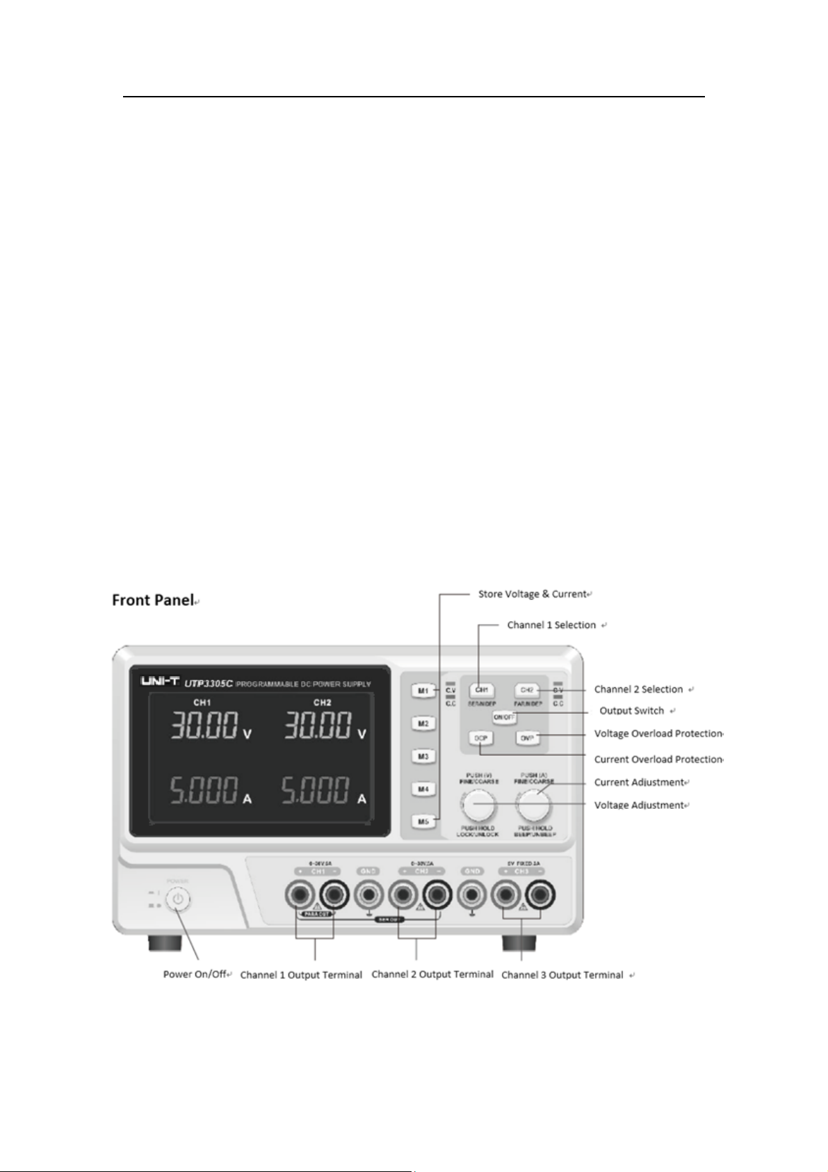
Function
UTP3000C Series User Manual
1. Voltage and Current Settings and Output
1. Press , the displayed voltage of CH1 flashes, during which turn voltage
adjustment knob to set the value; Press again to switch from voltage
to current, during which turn current adjustment knob to set the value; keep
pressingto switch between voltage and current. When the displayed voltage or
current is flashing, press the voltage or current knobto adjust resolution.
2. After setting the voltage and current values, press to output them.The
ON light will also be on; Press again to stop the output and ON light will
be out.
3
Page 5

2. Series and Parallel Settings
1. Series settings:
Press for 3s to enter into series mode and SER light will be on. Then
CH1 operation is shielded, and CH2 will actas the main control; Press
to enable/disable output.The connection method of series terminal is as below,
2. Parallel Operations:
Press for 3s to enter into parallel mode and PARA light will be on.
Then CH1 operation is shielded, and CH2 will act as the main control;
Press to enable/disable output. The connection method of parallel
terminal is as below,
UTP3000C Series User Manual
3. Recall and Output
No matter under what condition, you can have storage valuesrecalled by pressing
any key from M1 to M5.
4. Over Current Protection Setting
Press for 3s to enter into Over Current Protection (OCP) setting and OCP
SET light willflash; Press CH1/2 to select the channel, and turn the current knob to
adjust value; Press again for 3s, the device exists setting and OCP SET light
will beoff; Then the set current value will bedisplayed.
Short press to turn on OCPand OCP light will be on. Whencurrent is larger
than the value set in OCP, output willbe disabled; Press again to turn off
OCP.
4
Page 6

UTP3000C Series User Manual
5. Over Voltage Protection Setting
Press for 3s to enter into Over Voltage Protection (OVP) setting and OVP
SET light willflash; Press CH1/2 to select the channel, and turn voltage adjustment
knob to adjust value; Press again for 3s, the device exists setting and OVP
light will be off. Then the setvoltagevalue will bedisplayed.
Short press to turn on OVPandOVP light will be on. When voltage is larger
than the value set in OVP, output will be disabled. Press again to turn off
OVP.
6. Key Lock
After pressing the voltage knob for 3s, keys are locked; press it again for 3s, keys
are unlocked.
7. Turning on/off Buzzer
After pressing the current knob for 3s, the buzzer will be turned off; Press it again
for 3s, the buzzer will be turned on again.
5
Page 7

Remote Control
COM setting: set computer COM portsetting as below:
• Baud Rate: 9600
• Calibration Bit: None
• Data Bit: 8
• Stop Bit: 1
RS232 Interface Definition
UTP3000C Series User Manual
Communication protocol V2.0
Order Format: VSET<X>:<NR2>
1. VSET: Order Parameter
2. X: Channel
3. :Separator
4. NR2: Parameter
Order Description:
1. LOCK<NR2>
Function Description:Lock power supply operation panel
Example: LOCK1
Lock power supply operation panel
Example:LOCK0
Unlock power supply operation panel
2. ISET<X>: <NR2>
Function Description: Set current value
Example: ISET1:2.225
Set current value as 2.225A
3. ISET<X>?
Function Description: Read the set current value
6
Page 8

UTP3000C Series User Manual
Example: ISET1?
Returnset current value
4. VSET<X> : <NR2>
Function Description: Set voltage value
Example: VSET1:20.50
Set voltage value as 20.50V
5. VSET<X>?
Function Description: Read voltage value
Example: VSET1?
Return set voltage value
6. IOUT<X>?
Function Description: Read current output value
Example: IOUT1?
Read the set current value
7. VOUT<X>
Function Description: Read voltage output value
Example: VOUT1?
Read the set voltage value
8. OUT<Boolean>
Function Description: Turn on/off power supply output
Boolean: 0 off; 1 on
Example: OUT1 Turn on power supply output
9. BEEP<Boolean>
Function Description: Turn on/off buzzer
Example: BEEP1 Turn on buzzer
10. STATUS?
Function Description: Read power supply output status
Contents 8 bits in the following format
Bit Item Description
0 CH1 0=CC mode, 1=CV mode
1 CH2 0=CC mode, 1=CV mode
2,3,4,5 N/A
6 Output 0=Off, 1=On
7 N/A N/A
11. *IDN?
Function Description: Return to device model & factory information
Example: *IDN?
Contents UNI-T P33XC V2.0 (manufacturer, model name)
12. RCL<NR1>
Function Description:Storage recall by pressing keys from M1-M5
13. SAV<NR1>
Function Description: Storage setting
Example: SAV1 Stores the panel setting in memory number 1
14. TRACK<NR1>
7
Page 9

Function Description: Set series & parallel output
NR1:0=independent output; 1=series output; 2=parallel output
Example: TRACK1
15. OCP<Boolean>
Function Description: Turn on over current protection
Boolean: 0 OFF, 1 ON
Example: OCP1 Turn on OCP
16. OVP<Boolean>
Function Description: Turn on over voltage protection
Boolean: 0 OFF, 1 ON
Example: OVP1 Turn on OVP
17. OCPSTE: <X> : <NR2>
Function Description: Set OCP value
Example: OCPSTE1: 5.100
18. OVPSTE: <X> : <NR2>
Function Description: Set OVP value
Example: OVPSTE1: 31.00
UTP3000C Series User Manual
Technical Index
Note: The measurement below are taken in environment of 25 and after preheating℃
equipment for 5 minutes.
Model UTP3303C UTP3305C
Voltage Output 0-30V (CH1/CH2) 0-30V (CH1/CH2)
Current Output 0-3A (CH1/CH2) 0-5A (CH1/CH2)
Loading Effect
Voltage ≤0.01%+3mV ≤0.01%+5mV
Current ≤0.1%+5mA ≤0.1%+10mA
Power Supply Effect
Voltage ≤0.01%+3mV ≤0.01%+3mV
Current ≤0.1%+3mA ≤0.1%+3mA
Resolution Setting
Voltage 10mV 10mV
Current 1mA 1mA
Precision Setting (25℃±5℃)
Voltage ≤0.5%+20mV ≤0.5%+20mV
Current ≤0.5%+5mA ≤0.5%+10mA
Ripple (20-20M)
Voltage ≤1mV
Current ≤3mA
Output Temperature Coefficient
Voltage ≤150ppm ≤150ppm
Current ≤150ppm ≤150ppm
Read-back Resolution
8
≤2mV
rms
≤3mA
rms
rms
rms
Page 10

UTP3000C Series User Manual
Voltage 10mV 10mV
Current 1mA 1mA
Read-back Temperature Coefficient
Voltage ≤150ppm ≤150ppm
Current ≤150ppm ≤150ppm
Voltage Rise Delay
≤100ms
Voltage Rise Delay
(10% Rated load)
Parallel Load Effect
Voltage ≤0.1%+0.1V
Series Load Effect
Voltage ≤0.1%+0.1V
CH3 Output Parameter
Voltage Range 5V
Current Range 3A
Voltage Precision ±50mV
Loading Effect ±50mV
Accessories
User manual, Wire, PC software CD(only for model with
interface)
Weight & Size(mm)
252(W)×135(H)×370(D); UTP3303C×6.5kg, UTP3305C×9.1kg
≤100ms
(10% Rated load)
9
 Loading...