

Page 1
Page 2

Page 3

UTG9000BS/DS
DDS Function/Arbitrary Waveform Generator
Operating Manual
UTG9000BS/DS
Page 4

UTG9000BS/DS
Introduction
Thanks for purchasing our product. In order to ensure to use this instrument correctly for best
performance, please read this manual in details and keep it properly. This instrument is under
strictly quality control for production. All the parts go through screening and a series of perfor⁃
mance testing, environmental testing and safety testing which guarantee safety in proper us⁃
ing. It has the best working performance under the guidelines of working environment.
Page 5

1. General Description ………………………………… 1
2. Safety Summary……………………………………… 2
3. Panel Functions & Menu …………………………… 2
4. Use Method…………………………………………… 4
4.1 start up ……………………………………………… 4
4.2 waveform choose…………………………………… 4
4.3 Frequency setting ………………………………… 6
4.4 amplitude setting …………………………………… 8
4.5 DC drift setting ……………………………………… 9
4.6 Duty Cycle setting ………………………………… 10
4.7 AM setting ………………………………………… 11
4.8 FM setting ………………………………………… 12
4.9 Sweep setting……………………………………… 14
4.10 Burst setting ……………………………………… 15
4.11 ASK setting ……………………………………… 16
4.12 FSK setting ……………………………………… 18
4.13 PSK setting ……………………………………… 19
4.14 PWM setting……………………………………… 20
4.15 external frequency measurement……………… 21
4.16 arbitrary wave output …………………………… 22
4.17 arbitrary wave download and save …………… 23
5. Software for Arbitrary Waveform Programming … 23
5.1 Software interface ………………………………… 24
5.2 Arbitrary waveform programming ……………… 24
5.3 Data format and editing ………………………… 24
5.4 Arbitrary waveform download …………………… 25
6. Accessories ………………………………………… 25
7. Main Technical Specifications …………………… 25
Content
UTG9000BS/DS
Page 6

Thank you for purchasing DDS Function/Arbitrary Wave⁃
form Generator.
DDS function generator is the updated product of tradition⁃
al analog function generator with more function advantages
and better cost performance. It is now widely used in manu⁃
facturing, teaching and researching.
This series have the following features:
● DDS technique is applied with the same high frequency
stability and resolution as crystal oscillator and extreme low
frequency is realizable.
● VLSI and SMT are used. Auto-calibrating program with⁃
out mechanical potentiometer can insure the high reliability.
● Double channels output, frequency of both A/B channels
reach max limit of the instrument. (max output of channel B
of UTG9040BS/DS is 20MHz)
● Ten basic waveforms includes Sine, Square, Triangle,
Pulse, Up Ramp, Down Ramp, P- Exp, N- Exp, Sine (x) /x
and Noise wave.
● Modulation waveforms include AM, FM, PWM, Sweep,
Burst, ASK, FSK, PSK
●4.3’color TFT LCD (480 × 272) display, Chinese or Eng⁃
lish menu.
● Favorable human-machine interface with convenient op⁃
eration. Each one button to each waveform and modulation
waveform. The parameters can be keyed in by number but⁃
tons or by combined operation of buttons and pulse knob.
●All settings and conditions for waveforms are saved auto⁃
matically and can be recovered automatically.
● Convenient and practical software for arbitrary waveform
programming can download and save 16 arbitrary wave⁃
forms, edit and output 4 arbitrary waveforms at the same
time. The arbitrary waveforms could be output independent⁃
ly or in groups. (optional)
●USB interface (applied for DS series)
Please read this manual carefully before using and keep it
for reference. The instrument is of high quality and stable
reliability since it is manufactured strictly according to the
quality controlling standards.
1
UTG9000BS/DS
Page 7
● The protection from the instrument may be ruined if it is
not used as guided by the manual
● The power plug should be grounding protected.
● The instrument should be used in the specified condi⁃
tions as followed (temperature 0℃~40℃, humidity≤80%) ,
The best operation condition is at the indoor temperature
(around 25℃)
● As for the instrument with its sine wave frequency is ≤
20M, the signals of more than 20 Vpp(open- circuited) or
10Vpp (50Ω) cannot be connected to the signal output. If
the frequency is >20M the signals of more than 6 Vpp
(open-circuited) or 3Vpp (50Ω) cannot be connected to the
signal output.
● Replace the new fuse only after the power is switched
off and the specified fuse of rated current (220V/0.5A)
should be used.
● The protection of the product may be ruined when it can
not work properly. Please contact our sales department or
service station to get quick and effective after-sale service
if there is anything wrong with our product.
● The cover of the case cannot be opened except by pro⁃
fessional technicians.
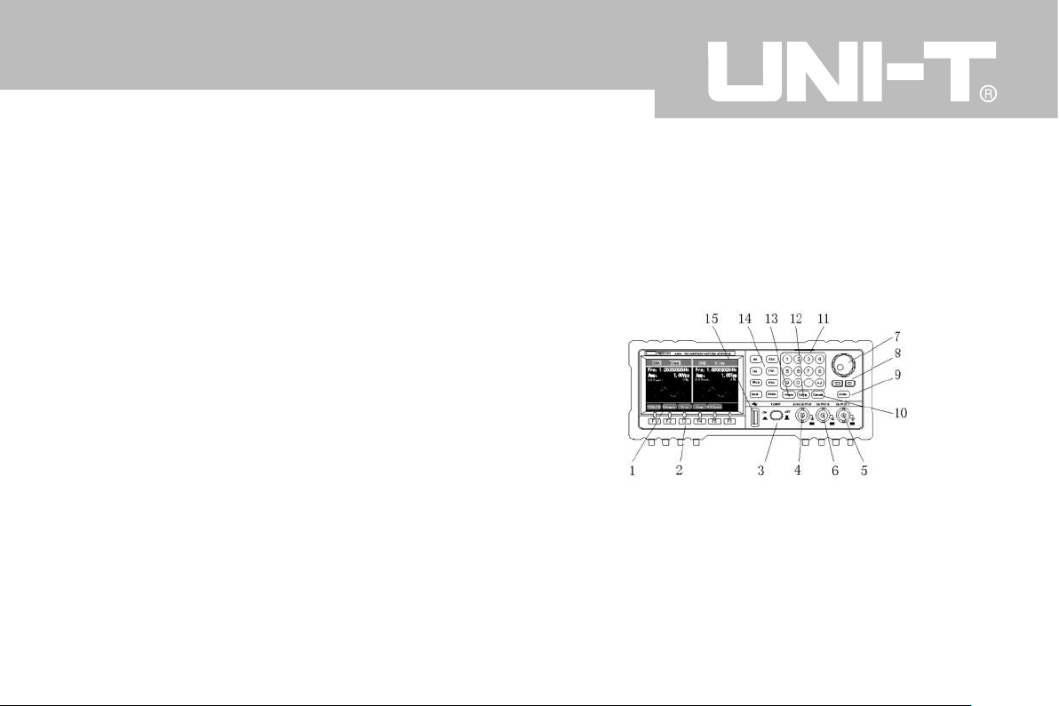
3.1 Front Panel as followed
1—4.3’color TFT LCD (480×272) display:display of all op-
erations and data settings with high resolution
2—Function key zone:There are 6 function keys. They are
of different functions according to different menus and the
corresponding functions are displayed down on LCD.
2
UTG9000BS/DS
Page 8

3—Power switch:key in to turn on and out to turn off.
4—Synchronization output:“SYNC OUTPUT”terminal out-
puts TTL level pulse wave which is used to indicate the
time of the output signal A issued. At this time the synchro-
nized signal can be input through external trigger port of
oscilloscope so the complex waveform of the product can
be stable to be observed conveniently.
5—CHA main output:It outputs all basic waveforms and
modulated signals. The output impedance is 50Ω.
6—CHB output:At the condition of basic waveform output it
has similar function as the main output CHA to output all
basic waveforms . At the condition of modulated waveform
output it outputs modulated wave while CHA outputs modu-
lated carrier wave.
7—Digital Knob:Roller for short. It is a novel digital part
which is used to choose, add or subtract the value when
there is any function to be modified or parameter in the
menu highlighted. The corresponding output changes corre-
spondingly when the roller works.
8—Direction keys of Left and Right:to choose bits when
changing the data with pulse switch. The right direction key
can delete the last number just input when setting numbers.
9—Enter:key to confirm and save the setting of signal fre-
quency, amplitude and other parameters directly by Num-
ber key. In model with function of arbitrary wave it should
be pressed to confirm the choosing of arbitrary waveform
in memory.
10—Cannel:Press it to exit from direct number setting of
parameters such as signal frequency and amplitude.
11—Number:set parameters
12—Config:has functions of external frequency measure-
ment, measuring arbitrary wave output and downloading.
(some functions are optional)
13—Wave:press it once and the key will be lightened with
one“beep”sound to enter the basic wave interface includ-
ing Sine, Square, Triangle, Pulse, Up Ramp, Down Ramp,
P-Exp, N-Exp, Sine (x) /x and Noise.
14—Modulation waveform key zone:each of 8 button to ac-
3
UTG9000BS/DS
Page 9
cess corresponding modulation waveforms of AM, FM,
Sweep, Burst, ASK, FSK, PSK and PWM.
15—USB interface (applied for DS series)
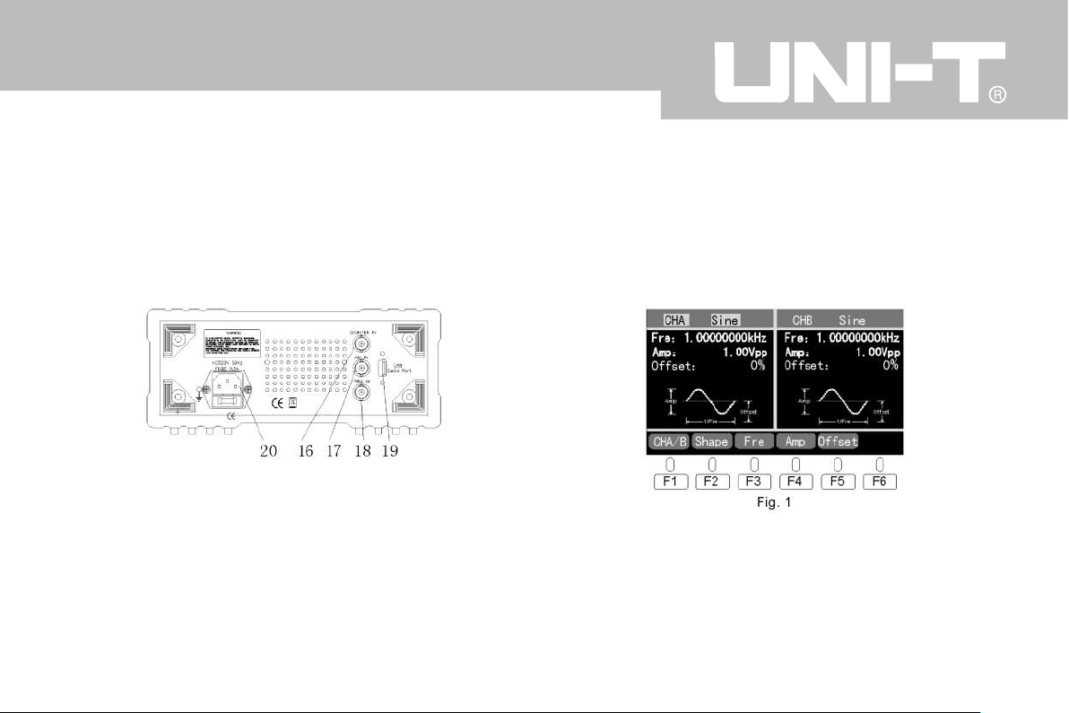
3.2 Back panel
16—COUNTER IN:external frequency input
17—AM IN:external AM signal input
18—TRIG IN:external trigger input of modulation
19—USB serial port (optional)
20—power input socket
4.1 Start up
Connect the power cord to the power supply socket and
press the power switch to enter the start up interface as
Fig. 1 below which is basic waveform interface with
“WAVE”button lightened.
4.2 Waveform choose
4.2.1 Basic waveform choose
Confirm the current interface. If it is not as Fig. 1 then
press the“Wave”button to access the basic waveform in-
4
UTG9000BS/DS
Page 10
terface.
Default setting is CHA output setting, wave choose and
Sine wave with the top line CHA and wave name highlight-
ed. If it is not highlighted press F2-Shape to enter the inter-
face of wave choose (similarly hereinafter) to make it.
Then use the roller to choose waves of Sine, Square, Tri-
angle, Pulse, Up Ramp, Down Ramp, P- Exp, N- Exp, Sine
(x) /x and Noise.
In CHA interface waves output through the high frequency
socket OUTPUT A. In CHB interface waves output through
the high frequency socket OUTPUT B Default settings is
routine of this product.
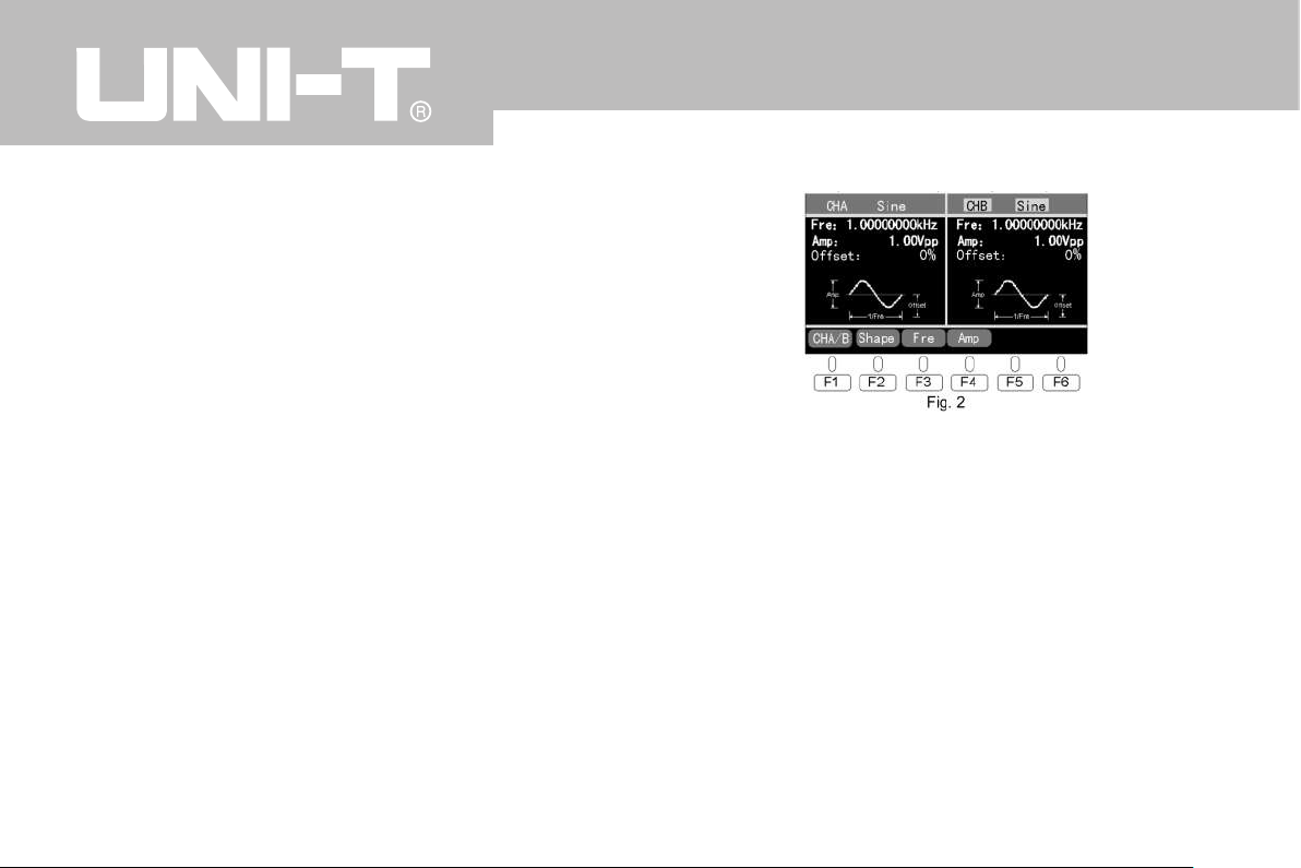
Press F1- CHA/B to switch between CHA and CHB setting
interface. When it is switched to CHB including the high-
lighted zone as Fig. 2, the way to choose waveform is simi-
lar to CHA as above to choose waves of Sine, Square, Tri-
angle, Pulse, Up Ramp, Down Ramp, P- Exp, N- Exp, Sine
(x) /x and Noise.
Note:Default frequency is 1.00000000KHz. Default ampli-
tude is 1.00Vpp. Default DC offset is 0%. All the three are
the routine default settings of this product.
4.2.2 modulated waveform choose
In the modulated waveform choose zone of the panel all of
8 buttons including AM, FM, Sweep, Burst, ASK, FSK,
PSK, PWM can be pressed once to access the correspond-
ing modulated wave interface. Modulated wave outputs
through OUTPUT A terminal on front panel .Wave to modu-
late outputs through OUTPUT B terminal.
5
UTG9000BS/DS
Page 11
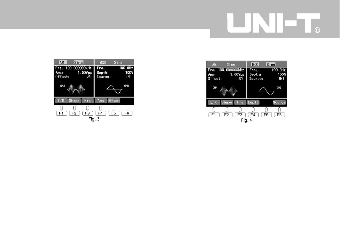
For example the AM wave interface is as Fig. 3 below.
Press F1- L/R to switch between the left and right interface.
The left interface is for carrier wave setting. Default setting
is wave choose and Sine wave. In start interface as Fig. 3
or press“F2- wave”that the carrier wave choose zone is
highlighted. Use roller to choose among 5 waves of Sine,
Square, Triangle, Up Ramp and Down Ramp.
Press F1 to switch to right interface as modulated wave set-
ting including highlighted zone as Fig. 4. The way to
choose wave is similar to carrier wave choose as above.
Use roller to choose among 5 waves of Sine, Square, Trian-
gle, Up Ramp and Down Ramp.
The ways to choose modulated waves of FM, Sweep,
Burst, ASK, FSK, PSK, PWM are similar as above.
4.2.3 Arbitrary wave choose (applied for DS series)
Press the button“Config”to access the setting interface to
operate arbitrary wave output and download in Model with
the arbitrary wave software and function. Refer to 4.16 arbi-
trary wave output.
4.3 Frequency setting
In wave setting interface press the Frequency correspond-
6
UTG9000BS/DS
Page 12
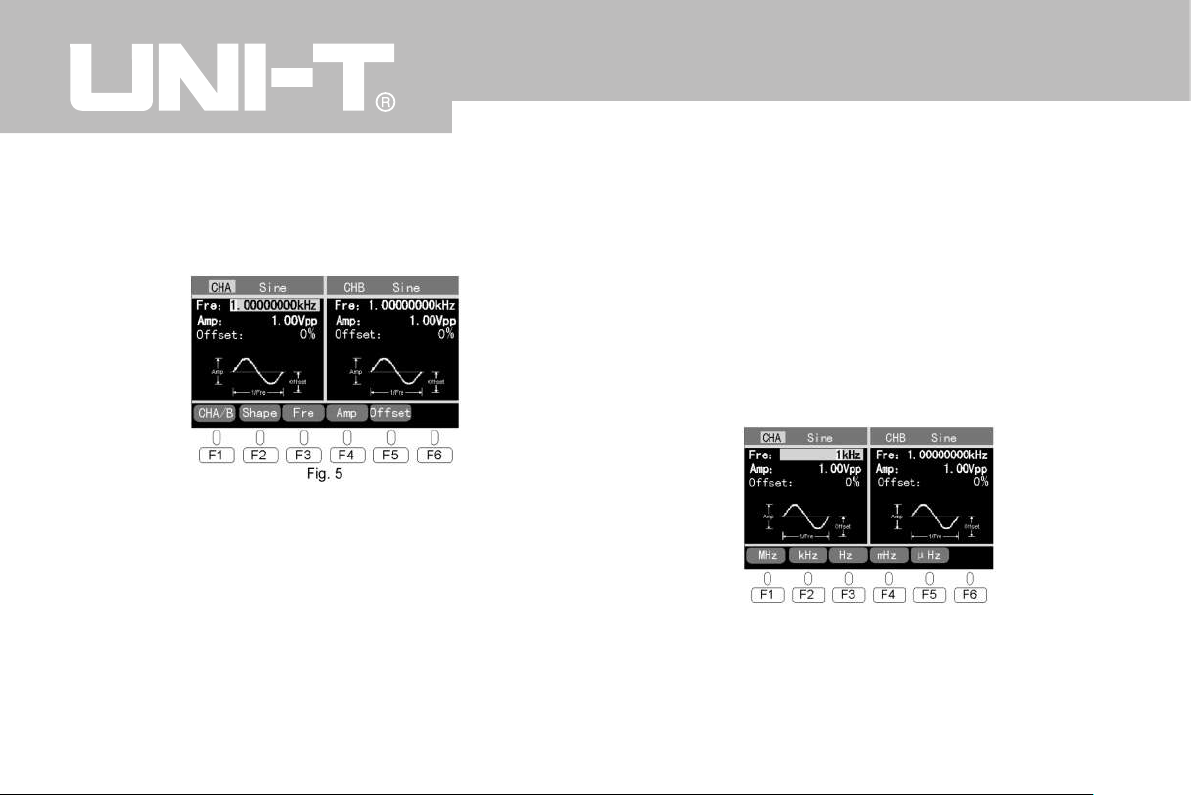
ing function key .The Frequency numbers will be highlight-
ed while the frequency parameters can be set.
For example in Sine interface as Fig. 5 press F3-Fre to set
the frequency and the interface is as below.
4.3.1 Set by roller and direction keys
Use the roller to change frequency setting and real- time
output.
Use the left and right direction keys to choose numbers
and unit of frequency and they will be highlighted and then
can be modified by the roller.
Note:When the direction key moves the highlighted zone
at“KHz”, use the roller control it will be switched among
“μHz”,”mHz”,”Hz”,”KHz”,”MHz”with the value multiplied
or divided by 103.
4.3.2 Set directly by number keys
The frequency can also be set by number keys directly
which is a quick way to set parameters. Press the number
keys the interface will change to the specific one of number
setting. For example, press number 1 and the interface is
as Fig. 6 below.
Keep pressing the number key the number will move for-
ward from right to left. During the number setting the new-
7
UTG9000BS/DS
Fig. 6
Page 13
est number input can be deleted from right to left by the
left direction key. After the number setting is done, press
the frequency corresponding function key to finish and con-
firm the setting of frequency and the signal of such settings
will output immediately.
Press the“Enter”key to confirm the value and the output
changes to new settings(frequency unit remains). During
the number setting process press the“cancel”key to exit
and return to the parameters before.
There’s upper and lower limit of frequency setting as per
kinds of waves and model of the product.
Sine 1μHz~upper limit
Square 1μHz~5MHz
Others 1μHz~1MHz
★ Except other frequency range indicated separately in
technical parameters
4.4 Amplitude setting
In wave setting interface press the Amp corresponding func-
tion key that the amplitude parameter will be highlighted to
be set.
For example in Sine interface the default amplitude is
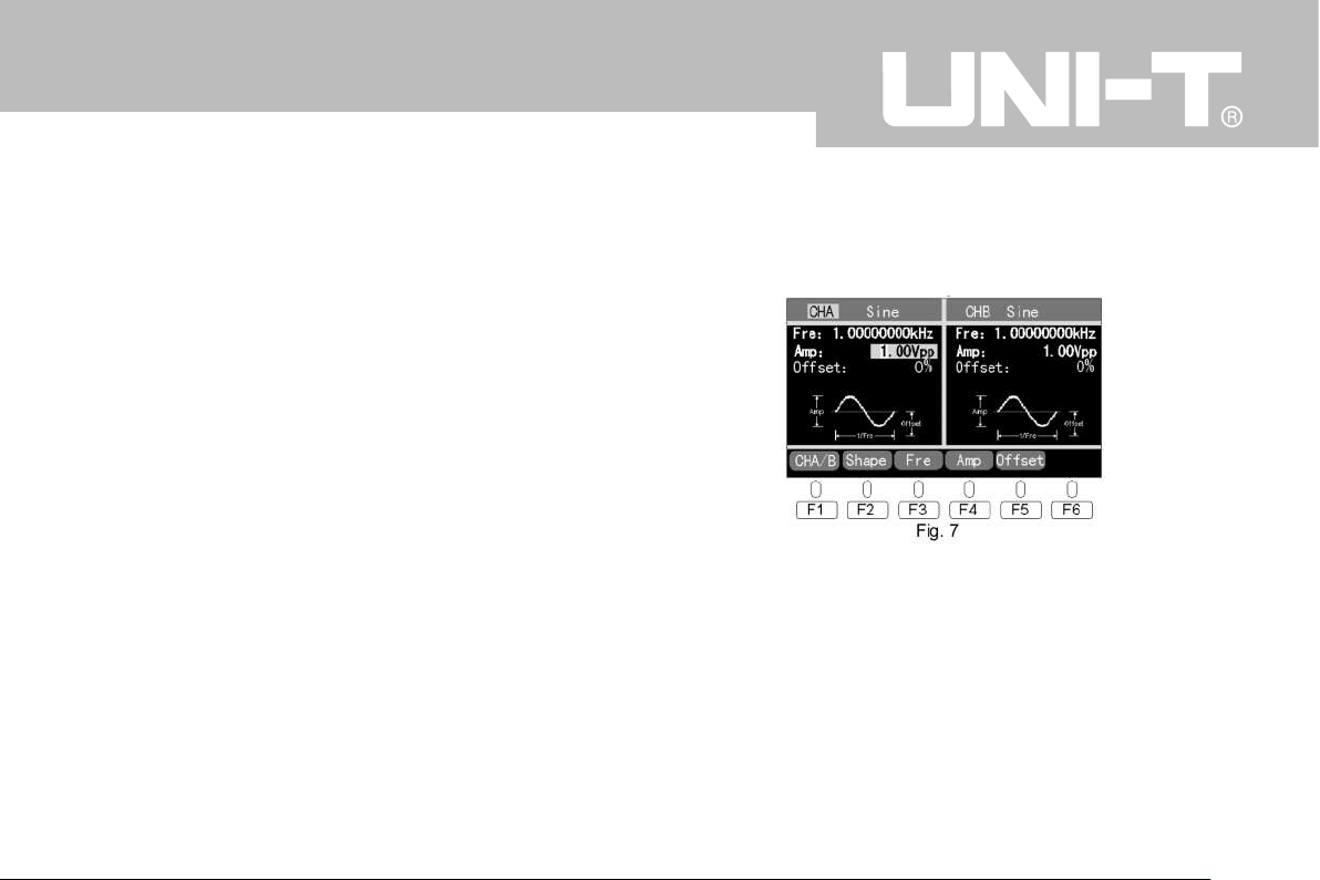
1.00Vpp. Press F4- Amp to set the amplitude and the inter-
face is as Fig. 7 below.
4.4.1 Set by roller and direction keys
Use the roller to change amplitude setting and real-time out-
put.
Use the left and right direction keys to choose numbers
and unit of amplitude as highlighted then use roller to modi-
fy them.
Note:When the direction key moves the highlighted zone
8
UTG9000BS/DS
Page 14
at“V”, use the roller control it will be switched between
“mV”and“V”with the value multiplied or divided by 103.
4.4.2 Set directly by number keys
The amplitude can also be set by number keys directly
which is a quick way to set parameters. Press the number
keys the interface will change to the specific one of number
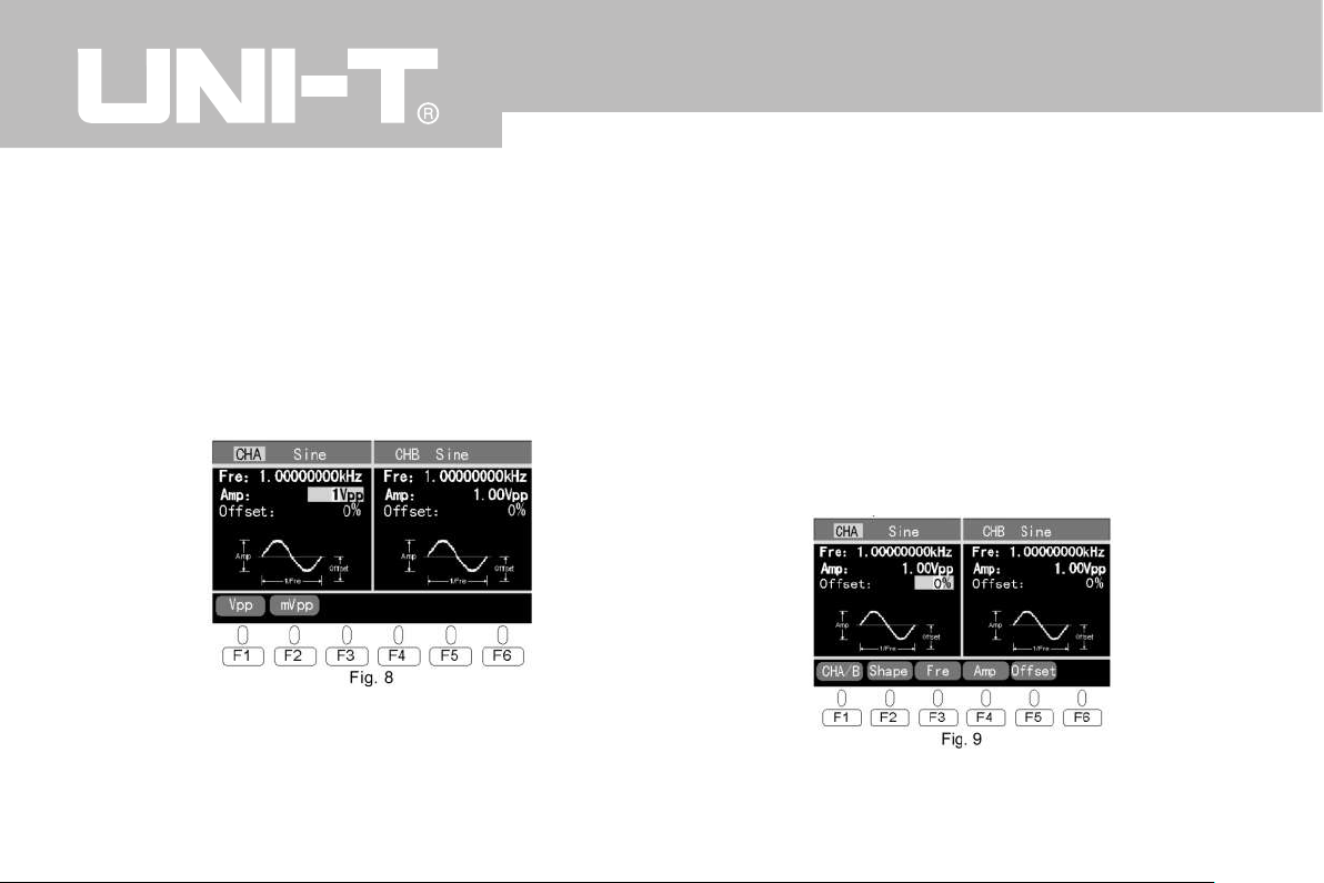
setting. For example, press number 1 and the interface is
as Fig. 8 below.
The way to set amplitude number is similar to the setting of
frequency.
There is upper and lower limit of amplitude as per kinds of
waves and model specifications.
4.5 DC offset setting
In this series DC offset is shown in the unit of % . In wave
setting interface press the Offset corresponding function
key and the DC offset number will be highlighted while the
DC offset parameters can be set. The default setting is 0%.
For example in Sine interface press F5-Offset and the inter-
face is as Fig. 9 below.
4.5.1 Set by roller and direction keys
9
UTG9000BS/DS
Page 15
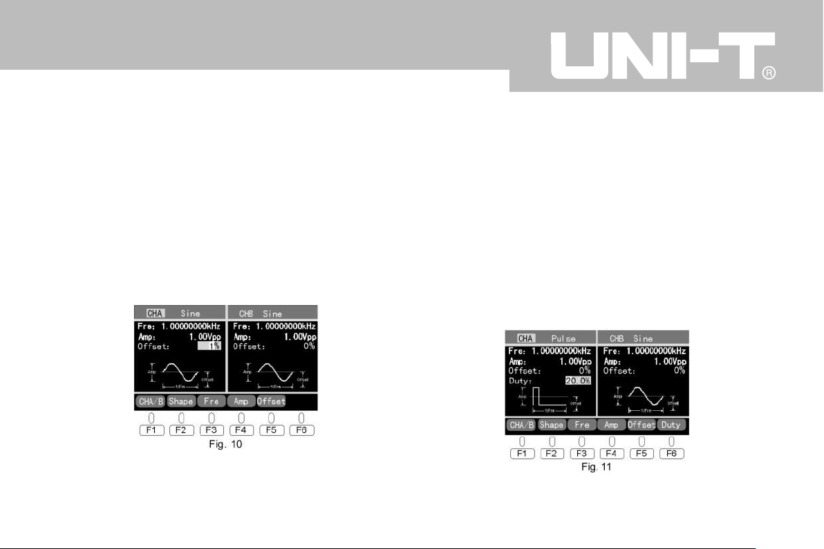
Use the roller to change DC offset +/- and setting and sig-
nal real-time output.
Use the left and right direction keys to choose numbers
and unit of DC offset.
4.5.2 Set directly by number keys
The DC offset can also be set by number keys directly
which is a quick way to set parameters. Press the number
keys the number input will be highlighted and flicker. For ex-
ample, press number 1 and the interface is as Fig. 10 below.
The way to set DC offset number is similar to the setting of
frequency.
The range of DC offset is ±100%.
4.6 Duty cycle setting
Duty cycle setting is only effective in Pulse and PWM.
In Duty cycle setting interface press Duty corresponding
function key and the Duty number will be highlighted while
the duty cycle parameters can be set. The Default setting
is 20%.
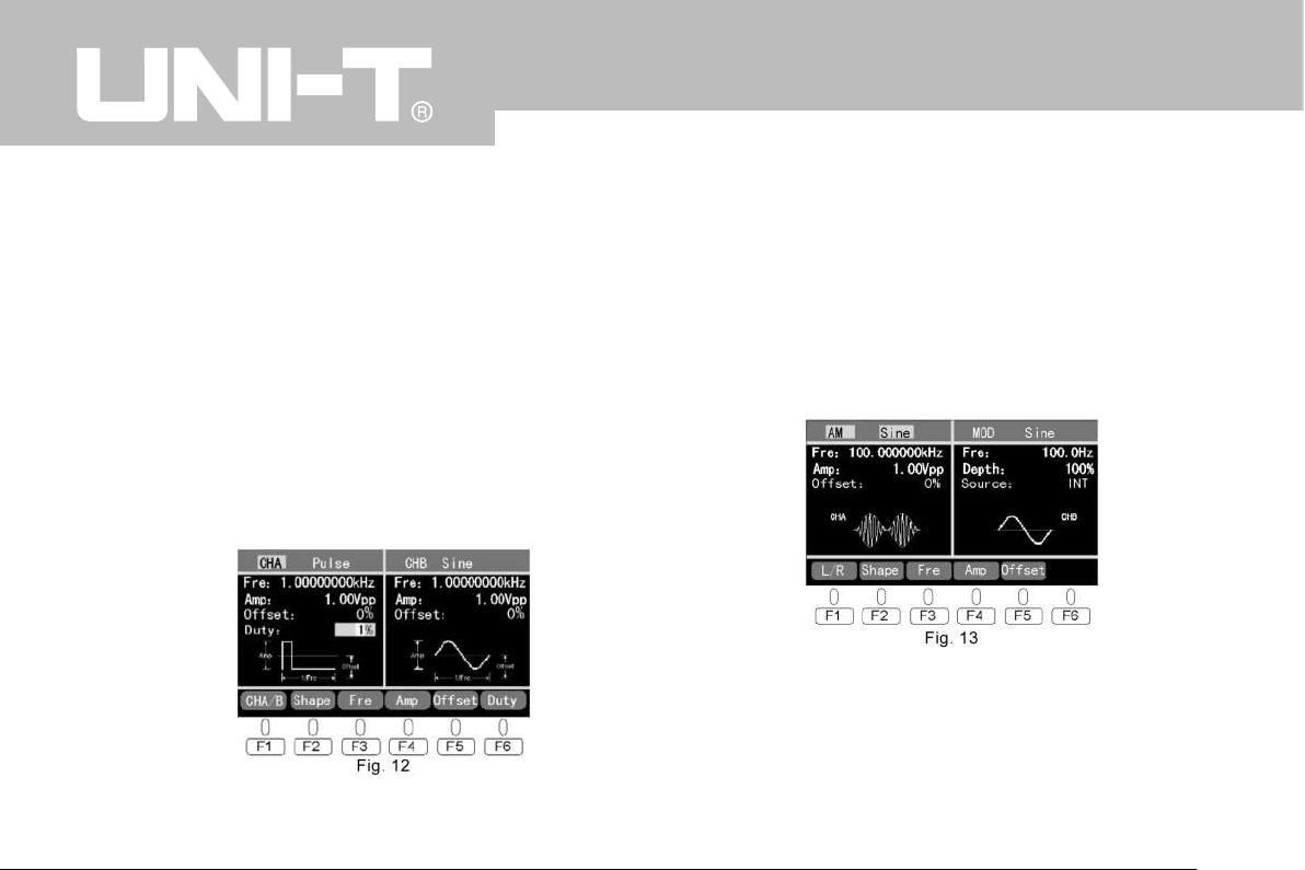
For example in Pulse interface Press F6-Duty and the inter-
face is as Fig. 11 below.
10
UTG9000BS/DS
Page 16
4.6.1 Set by roller and direction keys
Use the roller to change Duty cycle setting and real- time
output.
Use the left and right direction keys to choose numbers
and unit of Duty cycle.
4.6.2 Set directly by number keys
The Duty cycle can also be set by number keys directly
which is a quick way to set parameters. Press the number
keys the number input will be highlighted and flicker. For ex-
ample, press number 1 and the interface is as Fig. 12 be-
low.
The way to set Duty cycle number is similar to the setting
of frequency.
The range of Duty cycle is 0.1%~99.9%.
4.7 AM setting
Press the button AM to access the AM wave interface as
Fig. 13 below.
4.7.1 Carrier wave setting
In this interface:
F1- L/R is switch of left and right interface of AM carrier
wave and Modulated wave setting.
11
UTG9000BS/DS
Page 17
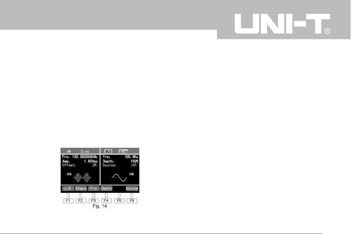
F2~F5 are function keys to set the frequency, amplitude
and DC offset of carrier wave. Refer to introductions above.
AM carrier waveform includes 5 waves of Sine, Square, Tri-
angle, Up Ramp and Down Ramp.
Default frequency setting of carrier wave is 100.000000kHz
Carrier wave frequency range:
Sine 1μHz~upper limit of frequency (20MHz max)
Square 1μHz~5MHz
Others 1μHz~1MHz
4.7.2 Modulated wave parameter setting
Press F1- L/R to switch to the right interface - modulated
wave setting as Fig. 14.
In this interface:
F1-L/R is switch of left and right interface.
F2~F3 are function keys to set modulated waveform and
frequency. The setting way is similar to carrier wave.
F4- Depth is modulation depth function key to set modulation depth. When it’s chosen the roller or the number keys
can be used to set parameters which is similar to the way
of DC offset setting.
F6-Source is to choose internal or external signal modula-
tion.
The modulation waveform includes 5 waves of Sine, Square,
Triangle, Up Ramp and Down Ramp.(the same below)
Modulation frequency:1mHz~20KHz. Default setting is
100.0Hz
The range of modulation depth is 0% ~100% . Default setting is 100%。
When the source is external the modulation is up to the
waveform, frequency and amplitude of external modulation
signal.
4.8 FM setting
12
UTG9000BS/DS
Page 18
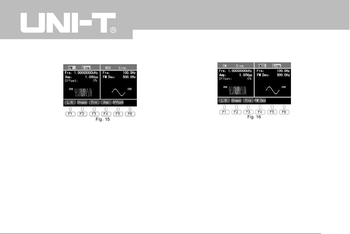
Press the button FM to access the FM wave interface as
Fig. 15
4.8.1 Carrier wave setting
In this interface:
F1- L/R is switch of left and right interface of carrier wave
and FM parameter setting.
F2~F5 are function keys to set the waveform, frequency,
amplitude and DC offset of carrier wave. Refer to introduc-
tions above.
The waveform and frequency range is similar to those of
AM wave.
4.8.2 Modulated wave parameters setting
Press F1 to switch to the right interface - modulated wave
setting as Fig. 16.
In this interface:
F1-L/R is switch of left and right interface.
F2~F3 are function keys to set modulated waveform and
frequency. The setting way is similar to carrier wave.
F4-Dev is Frequency offset function key. When it’s chosen
the roller or the number keys can be used to set parame-
ters which is similar to the way of frequency setting as
above.
Note: the FM signal is fixed to internal modulation.
Modulation frequency:1mHz~20KHz .
The range of modulation offset must be less than the differ-
13
UTG9000BS/DS
Page 19
ence between the upper limit of carrier wave frequency &
waveform frequency and the carrier wave frequency. De-
fault setting is 500.0Hz.
4.9 Sweep setting
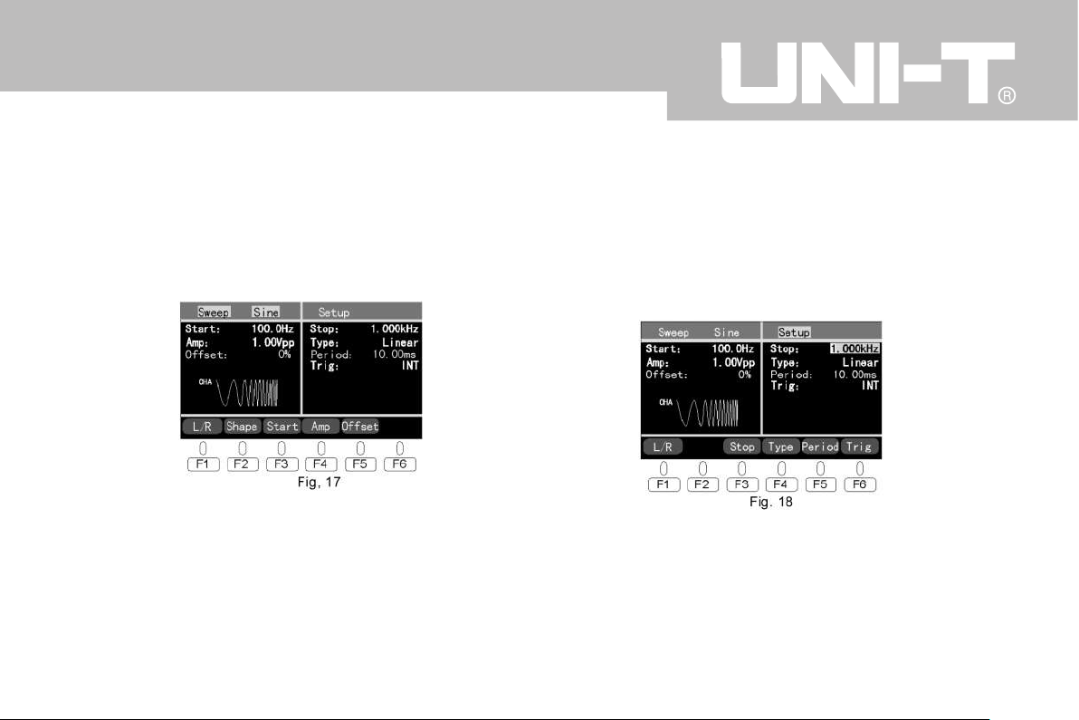
Press the button Sweep to access the Sweep interface as
Fig. 17
4.9.1 Carrier wave setting
In this interface:
F1- L/R is switch of left and right interface of carrier wave
and SWEEP parameter setting.
F2, F4 and F5 are function keys to set the parameters of
carrier wave. Refer to introductions of AM setting above.
F3- Start is to set the sweep start frequency. The setting
way is similar to carrier wave setting.
The waveform and frequency range of Sweep carrier wave
is similar to those of AM carrier wave.
4.9.2 Sweep parameters setting
Press F1 to switch to the right interface - Sweep setting as
Fig. 18
In this interface:
F1-L/R is switch of left and right interface.
F3- Stop is for setting sweep termination frequency. The
way to set is similar to the start frequency setting.
F4-Type is for sweep method choosing from Linear or Log
14
UTG9000BS/DS
Page 20
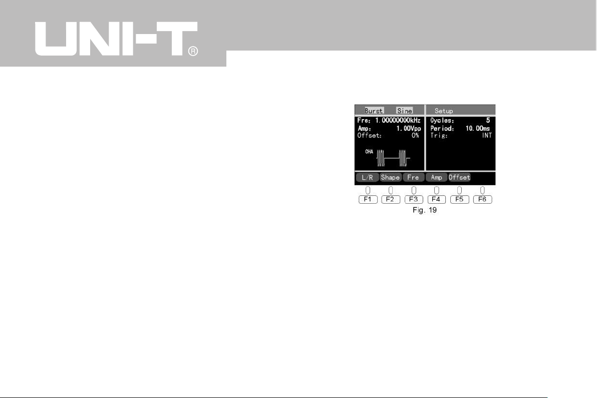
with roller.
F5- Period is for sweep period setting. When it’s chosen
the roller or the number keys can be used to set parame-
ters which is similar to the way of DC offset setting.
F6-Trig is to choose external or internal trigger signal
Note: the range of sweep termination frequency is the
same to the sweep start frequency.
Sweep period:1ms ~100.0s,default as 10.00ms
When external trigger is chosen the function generator out-
puts start frequency and waits to be triggered. It outputs
one sweep when receiving one TTL pulse from Trig IN at
back panel with all parameters as set and displayed by orig-
inal interface. After When the scanning output is done, the
function generator outputs start frequency and wait for the
next trigger.
The trigger period should be larger than or equal to the
scanning rate +1ms. The trigger signal in the period will be
neglected.
4.10 Burst setting
Press the button Burst to access the FM wave interface as
Fig.19
4.10.1 Carrier wave setting
In this interface:
F1- L/R is switch of left and right interface of carrier wave
and Burst parameter setting.
F2~F5 are function keys to set the parameters of carrier
wave. Refer to AM carrier wave setting above.
The waveform and frequency range of Burst carrier wave is
similar to those of AM carrier wave.
4.10.2 Burst parameters setting
Press F1-L/R to switch to the right interface - Burst setting
15
UTG9000BS/DS
Page 21
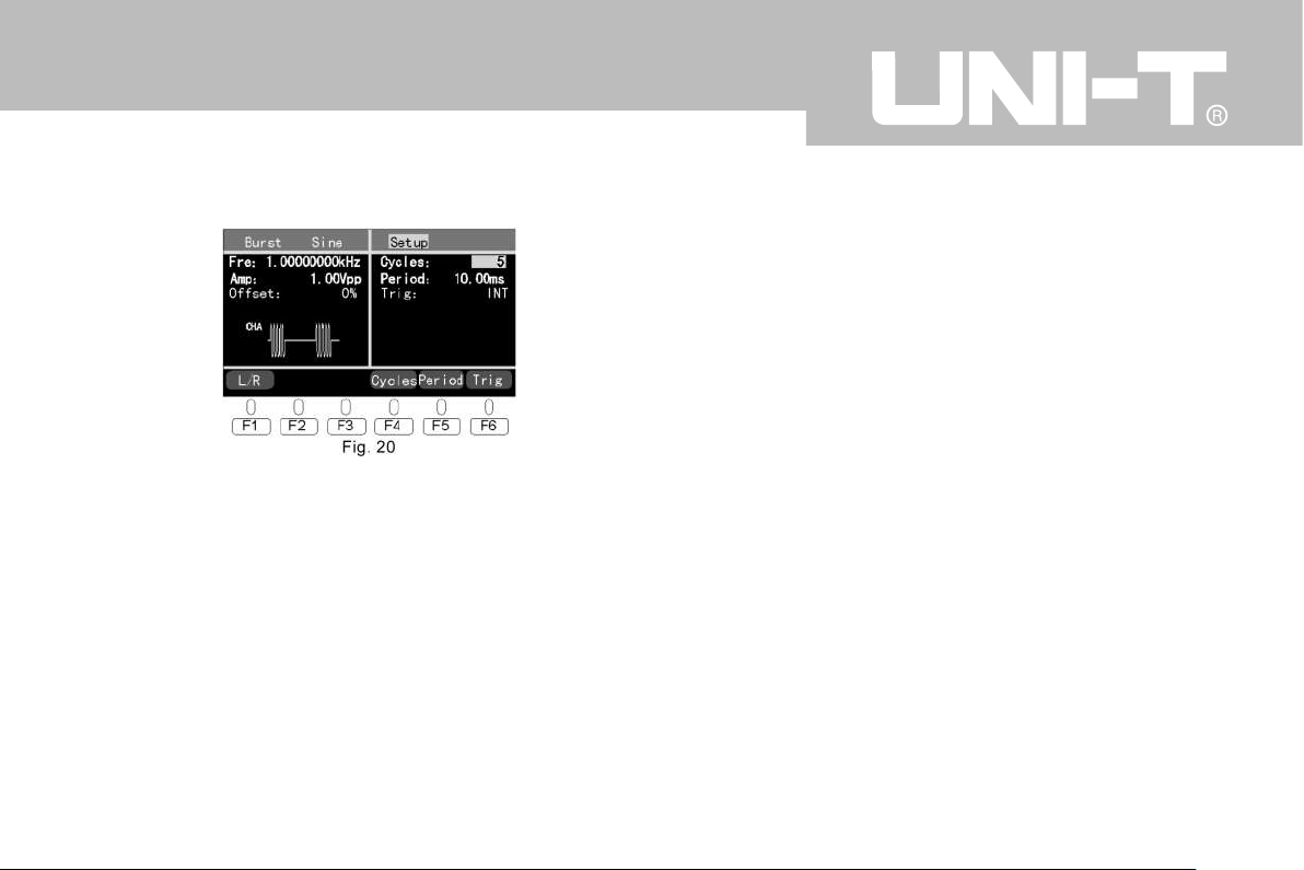
as Fig. 20
In this interface:
F1-L/R is switch of left and right interface.
F4-Cycles is for waveform cycle times(burst count) setting.
When it’s chosen the roller or the number keys can be
used to set parameters.
F5-Period is for burst period setting. When it’s chosen the
roller or the number keys can be used to set parameters.
F6-Trig is for external or internal trigger choosing.
Waveform cycle times are 1~60000 with default as 5.
Burst period is 1ms ~100.0s with default as 10.00ms.
Both internal and external trigger works for Burst with de-
fault as internal trigger.
When internal trigger is chosen, it constantly outputs cycle
numbers.
Burst period will decide the time span between burst fre-
quency and burst.
The burst cycle should be long enough and meet the condi-
tions below:
Burst cycle>burst numbers/wave frequency + 1ms
When external trigger is chosen, each time the function
generator will output one waveform with specified cycle
number (burst) when it receives the trigger. After the opera-
tion is done the function generator will stop and wait for the
next trigger.
4.11 ASK setting
Press the button ASK to access the ASK interface as Fig.
21
16
UTG9000BS/DS
Page 22
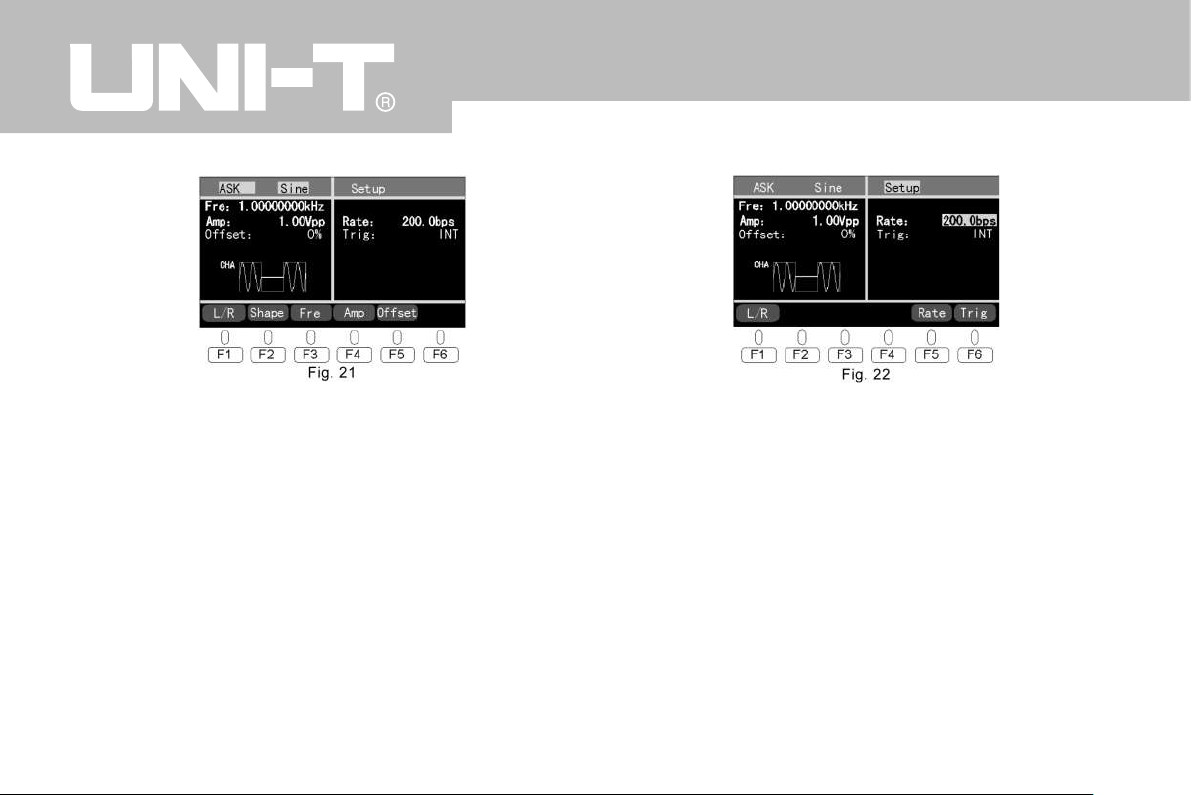
4.11.1 Carrier wave setting
In this interface:
F1- L/R is switch of left and right interface of carrier wave
and ASK parameter setting.
F2~F5 are function keys to set the parameters of carrier
wave. Refer to AM carrier wave setting above.
The waveform and frequency range of ASK carrier wave is
similar to those of AM carrier wave.
4.11.2 ASK parameters setting
Press F1 to switch to the right interface - ASK setting as
Fig. 22
In this interface:
F1-L/R is switch of left and right interface.
F5- Rate is for ASK rate setting with similar setting way to
the way of amplitude setting.
F6-Trig is for external or internal trigger choosing with roller.
Both internal and external trigger work for ASK and default
is internal.
ASK internal modulated waveform is fixed as symmetrical
square with duty cycle of 50%(i.e. 0101…).
The rate range is 0.1bps~1Mbps with default as 200.0bps.
If external trigger is chosen, the function generator will re-
ceive the TTL signal from trigger input on the back panel.
17
UTG9000BS/DS
Page 23
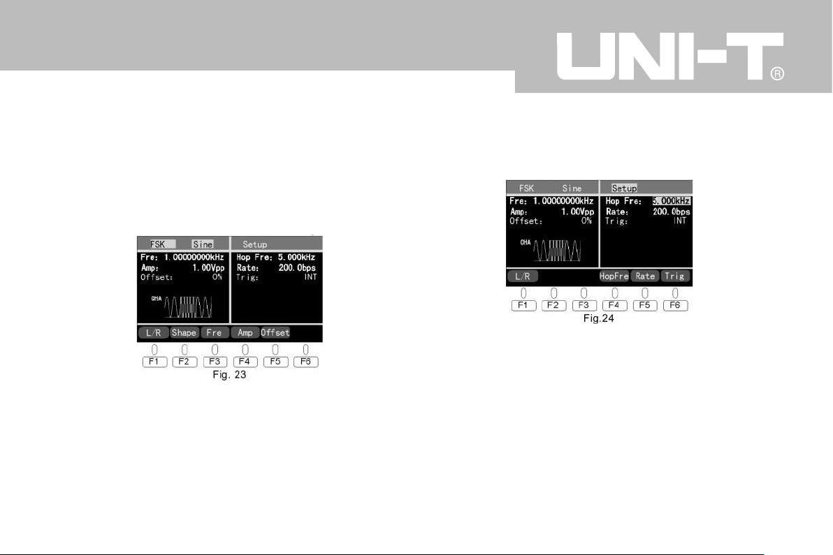
When the signal is low level (rate 0) there’s no output of
carrier wave and when the signal is high level (rate 1) the
carrier wave will output.
4.12 FSK setting
Press the button FSK to access the FSK interface as Fig.
23
4.12.1 Carrier wave setting
In this interface the way to set parameters is the same to
ASK.
The FSK waveform and frequency range is the same to
AM.
4.12.2 FSK parameters setting
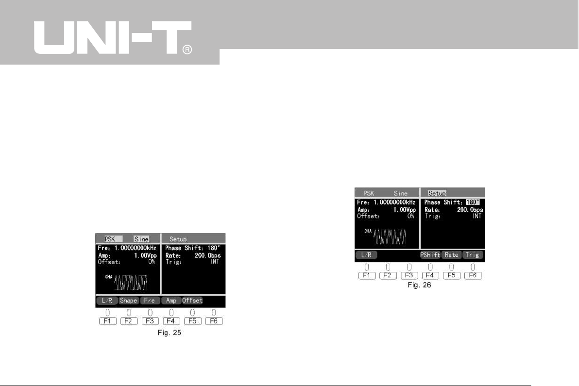
Press F1 to switch to the right FSK setting interface as
Fig. 24
In this interface:
F1-L/R is switch of left and right interface.
F4-Hop Fre is for FSK hopping frequency setting.
F5-Rate is for FSK rate setting with the same way to ASK
F6-Trig is for external or internal trigger choosing with roller.
The hopping frequency range is the same to the carrier
wave with default as 5.000KHz.
Both internal and external trigger work for FSK and default
is internal.
18
UTG9000BS/DS
Page 24
FSK internal modulated waveform is fixed as symmetrical
square with duty cycle of 50%(i.e. 0101…).
The rate range is 0.1bps~1Mbps with default as 200.0bps.
If external trigger is chosen, the function generator will re-
ceive the TTL signal from trigger input on the back panel.
When the signal is low level (rate 0) the carrier wave will
output and when the signal is high level (rate 1) the hop-
ping frequency will output.
4.13 PSK setting
Press the button PSK to access the PSK interface as Fig.
25
4.13.1 Carrier wave setting
In this interface the way to set parameters is the same to
ASK.
The FSK waveform and frequency range is the same to
AM.
4.13.2 PSK parameters setting
Press F1 to switch to the right interface - PSK setting as
Fig. 26
In this interface:
F1-L/R is switch of left and right interface.
F4-P Shift is for PSK phase shift setting.
F5-Rate is for PSK rate setting with the same setting way
19
UTG9000BS/DS
Page 25
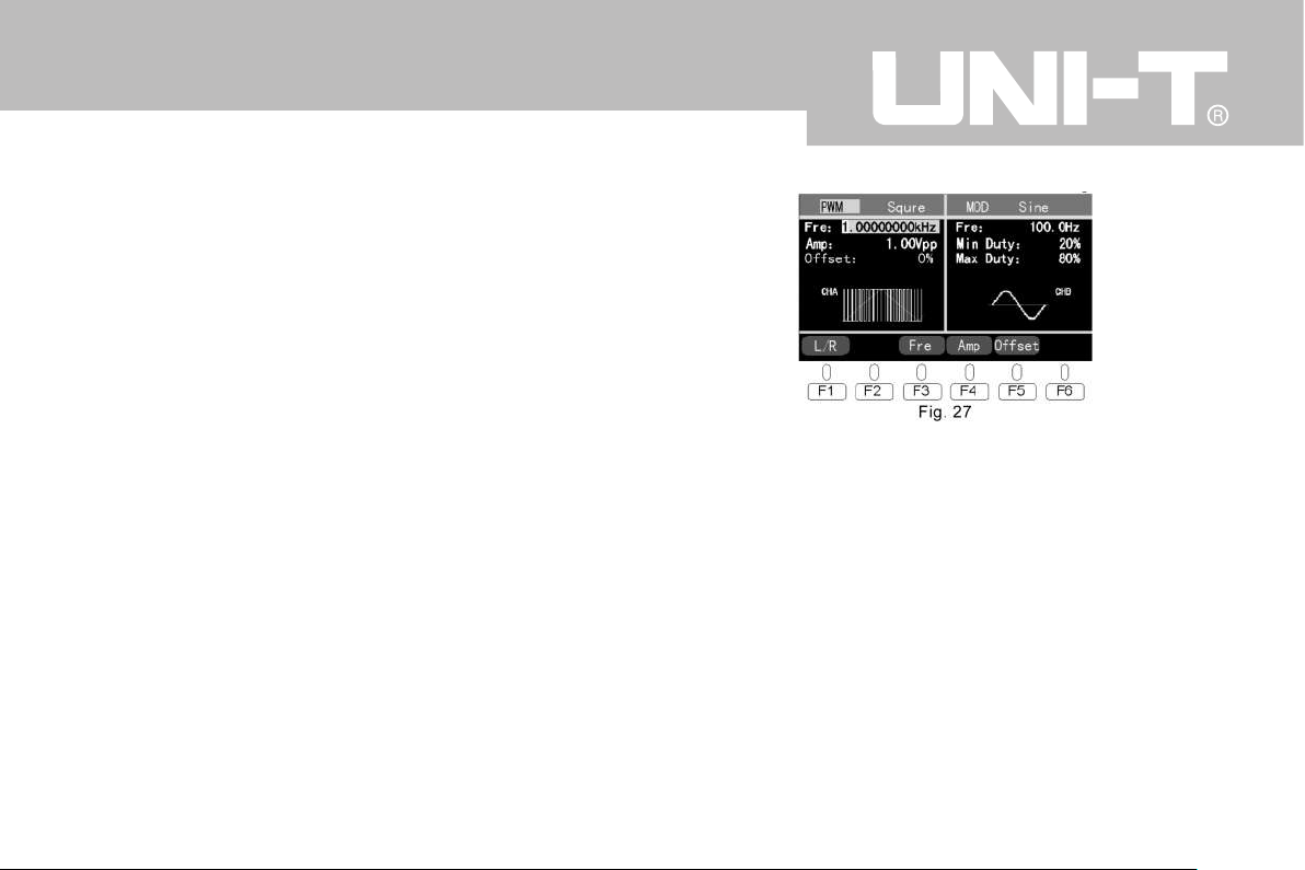
to ASK
F6-Trig is for external or internal trigger choosing with roller.
PSK phase shift range is -180°~180° with default as180°.
Both internal and external trigger work for PSK and default
is internal.
PSK internal modulated waveform is fixed as symmetrical
square with duty cycle of 50%(i.e. 0101…).
The rate range is 0.1bps~1Mbps with default as 200.0bps.
If external trigger is chosen, the function generator will re-
ceive the TTL signal from trigger input on the back panel.
When the signal is low level (rate 0) the carrier wave will
output and when the signal is high level (rate 1) the hop-
ping phase will output.
4.14 PWM setting
Press the button PWM to access the PSK interface as Fig.
27
4.14.1 Carrier wave setting
F1-L/R is switch of left and right interface for carrier wave
and modulated wave setting.
F3~F5 are for carrier wave parameters setting with same
setting way of AM carrier wave.
PSK carrier waveform is fixed as symmetrical square with
duty cycle of 50%.
Frequency range is 1μHz~5MHz with default 1.00000000KHz.
4.14.2 PWM parameters setting
Press F1 to switch to the right interface - PWM setting as
20
UTG9000BS/DS
Page 26
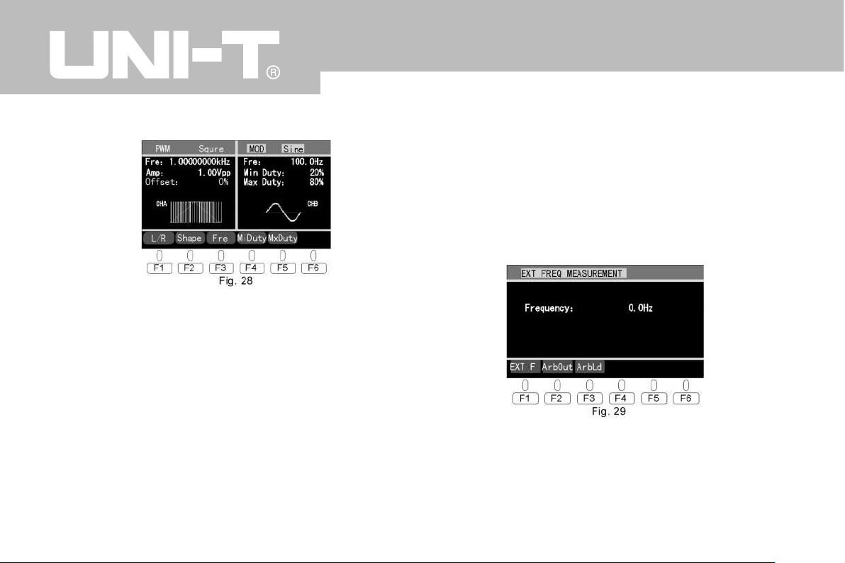
Fig. 28
In this interface:
F1-L/R is switch of left and right interface.
F2~F3 are for modulated waveform and frequency setting.
See antecedent.
F4-Mi Duty is for minimum duty ratio setting. When it’s cho-
sen both roller and number keys could set it in the same
setting way to duty ratio.
F5-Mx Duty is for maximum duty ratio setting in the same
setting way to Min Duty.
Modulated wave frequency is 100mHz~20KHz with default
as 100.0Hz
The range for duty ratio is 0.1%~99.9%.
PWM signal is fixed as internal modulated.
4.15 External frequency measurement
This product has function of external frequency measurement. Press the button“Config”to access the start inter-
face with default function of measuring external frequency
as Fig. 29 below.
In this interface external signal inputs through“OUNTER
IN”on back panel and the product will measure automati-
cally and show the result.
21
UTG9000BS/DS
Page 27
4.16 Arbitrary wave output (applied for DS series)
Arbitrary wave outputs through the terminal CHA.
Press the button“Config”to access the original interface
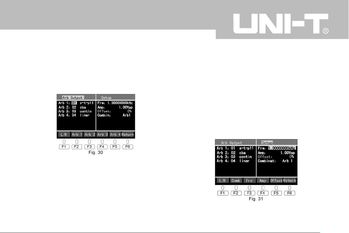
as Fig. 29 and then press F2- ArbOut to enter the arbitrary
wave operating interface as Fig. 30 below.
The left interface displays the saved pages and name(if
there is name when the arbitrary wave is downloaded and
saved) of current 4 arbitrary waves.
F1-L/R is switch of left and right interface for carrier wave
on left and arbitrary wave output setting on right.
Press F6-return to return the interface of Fig. 29.
4.16.1 Choose arbitrary wave
In the interface of Fig. 30 press F2~F5 to choose among
“Arb1”~”Arb 4” and then use the roller to choose the
saved waveform and press“Enter”to confirm the output.
The default setting is“Arb 1”so to change the setting to
output waveforms of“Arb2”,“Arb 3”,“Arb 4”or combined
the right interface should be accessed.
4.16.2 Arbitrary wave output parameters setting
Press F1-L/R to switch to the setup interface as Fig. 31
22
UTG9000BS/DS
Page 28
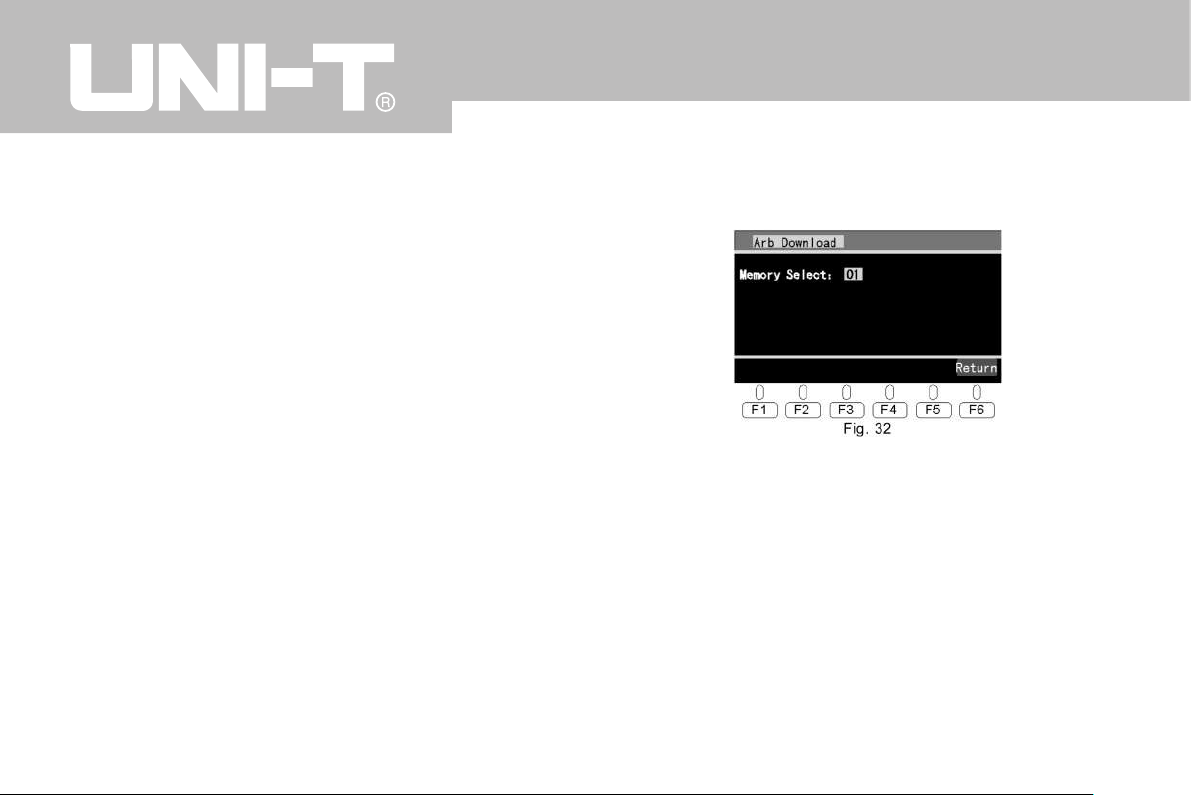
F2- Combin is for combined ways of output choosing with
roller to choose single output of Arb1, Arb2, Arb3, Arb4 or
combined output of Arb1-2, Arb2-3, Arb 3-4, Arb 1-4.
F3~5 is for frequency, amplitude and DC offset arbitrary
wave output setting. Refer to the setting way of AM carrier
wave.
F6-Return is for returning to Config setup original interface.
The frequency range of arbitrary wave is 100mHz~1MHz.
★ The frequency and amplitude of arbitrary wave output
are determined by the wave created by the arbitrary wave
software on PC.
4.17 Arbitrary wave download and save (applied for DS se-
ries)
Install the drive on PC and open the arbitrary wave soft-
ware. Connect the product with PC through USB to down-
load and save arbitrary waves.
First create or load waveform in the software, name it(or
skip), choose proper parameters such as port numbers.
See 5. Software for Arbitrary Waveform Programming.
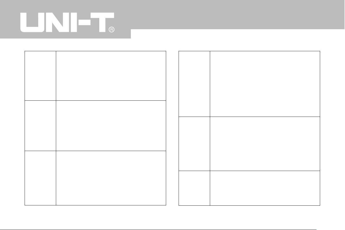
In Config setting interface as Fig. 29 press F3-ArbLd to ac-
cess the start interface of arbitrary wave downloading and
saving as Fig. 32
Use the roller to choose the page 01~16 to save and press
download button on PC afterwards. On the interface there
will be display of“loading...”and after downloading is com-
pleted display of“OK” together with the waveform name
(blank if no name). Then choose another page to continue
downloading another wave and 16 different waves can be
saved in this product.The page can be reedited with the
newest wave saved. F6- Return for returning to the Config
setting interface as Fig. 29.
5. Software for Arbitrary Waveform Programming(applied
23
UTG9000BS/DS
Page 29
for DS series)
It’s a green software on PC that no need to be installed. It’
s run in Windows and with the mouse you can conveniently
draw, revise, save or download any arbitrary waveform.
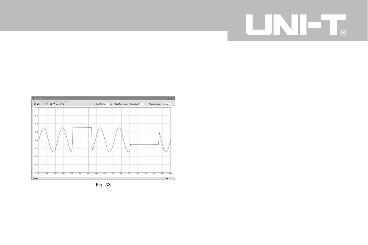
5.1 Software interface
The software interface is as Fig. 33. On top is the pulldown menu. Also there’s another operation way of icon
buttons under the menu line which is visual and simple.
Press one with the left mouse button to access correspond-
ing mode of operation. When the arrow is on one button
there will be description of the function under.
5.2 Arbitrary waveform programming
Left mouse button draw curve
Right mouse button draw straight line
Click by left mouse button place the remark
It’s very convenient to draw arbitrary waveform with the
functions above by the mouse. For those waveforms which
require the sine law or symmetry there’re basic wave of
sine or square wave in system to be modified on.
★ The frequency and amplitude of arbitrary wave output
are relevant to the wave parameters created by the arbi-
trary wave software on PC.
5.3 Data format and editing
Data support by the software has two formats of own for-
mat and text format. Arbitrary waveform drawn can be
saved and read in.
The own format is used to save waveform data created by
24
UTG9000BS/DS
Page 30

arbitrary waveform programming software.
The text format is used for the arbitrary waveform program-
ming software to read in waveform files created by user in
other methods with the file as .txt.
Txt file can be opened and edited in“notepad”interface
only if keyed in in hexadecimal. Every 8 numbers are re-
garded as one dot of the wave. There should be space be-
tween dots and the size of the number is related to the
height of the wave dot. If less than 8 numbers it is regard-
ed as default height. The highest corresponds to 1big, the
second highest corresponds to 1/16 big and ... The data
range is 0~7FFFFFFF and the corresponding waveform
value is 1 at max and -1 at min.- 1~1 stands for the peak
value range of signal change.
Text file which is edited can be opened in arbitrary wave
software interface to be modified, reviewed, downloaded
and saved.
5.4 arbitrary waveform download
1. Before downloading the drive should be installed on PC
side and the serial port number to which of PC the genera-
tor is connected should be confirmed so it can be chosen
in the pull- down menu of the software when waveform
downloading or there may be error.
2. choose resolution ratio. The software has 4 resolution ra-
tios of 1,2,4 and 8. Smaller number means higher resolu-
tion for editing waveform with lower frequency while larger
number means lower resolution for editing waveform with
higher frequency.
3. Download. Click the menu of download and click start.
There’s display of“loading...”in the interface and“OK”
when downloading is finished.
6. Accessories
●Fuse 1 pcs (installed on machine)
●Power cord 1pcs
●Double Q9 connection cord 1pcs
●Instruction manual 1pcs
25
UTG9000BS/DS
Page 31

WAVE
Arbitrary
wave
frequency
specifications
Sine, Square, Triangle, Pulse, Up Ramp,
Down Ramp, P-Exp, N-Exp, Sine (x) /x,
Noise
Saved waveform:16
Output waveform:1~4 single or combined
Length of wave saved:32x1k (1024) bit
Resolution:12 bit
Sample rate:131 Msa/s
Sine:1μHz ~upper limit
(max output of CHB is 20MHz)
Square:1μHz~5MHz
Other waves:1μHz ~1MHz
Highest resolution:1μHz
Long-term stability:50ppm (0°C~40°C )
Short-term stability:1ppm (after turning on
and heat stable)
Accuracy:0.4Hz (>100 Hz)
0.1μHz (<100mHz)
26
UTG9000BS/DS
7. Main specifications
Signal
features
CHA
Output
features
sine:(50Ω impedance,1Vpp output)
Harmonic distortion:<20kHz -60dBc
20kHz~1MHz -50dBc
1MHz~10MHz -40dBc
10MHz~20MHz -30dBc
square:(50 Ω impedance 1Vpp output)
Rise/fall time:<25ns
Overshoot:<5%
Asymmetry:0.1%
Pulse:
Duty cycle:0.1%~99 .9% (<10kHz)
1%~99% (<100kHz)
3%~97% (<1MHz)
Triangle, ramp:linear (1kHz) <0.1%
waveform:function waveform, modulation
waveform, arbitrary waveform
amplitude:
(to open circuit) 1mVpp~20Vpp
Sine wave >20MHz is 1mV~5Vpp
(to 50Ω) 0.5mVpp~10Vpp
Sine wave >20MHz is 0.5mV~2.5Vpp
Output impedance:50Ω
Sine flatness:5 %
DC offset:-100%~100% peak value
Page 32
ASK
FSK
PSK
INTERNAL
AM
EXTERNAL
AM
Rate:0.1bps~1 Mbps
trigger method:internal, external
Carrier wave frequency:1μHz~upper limit of
waveform frequency (max 20MHz)
Carrier waveform:sine, square, triangle, up
ramp, down ramp
FSK jumping frequency range:
1μHz~upper limit of waveform frequency
(max 20MHz)
PSK phase shift range:-360°~360°
Carrier waveform:sine, square, triangle, up
ramp, down ramp
Carrier wave frequency:1μHz~upper limit of
waveform frequency
Modulation waveform:sine, square, triangle,
up ramp, down ramp
Modulation frequency:100mHz~20kHz
AM depth:0%~100 %
Input impedance:1kΩ
AM depth:controlled by output amplitude
and external modulation signal amplitude
27
UTG9000BS/DS
CHB
Output
features
Sweep
Burst
waveform:function waveform
amplitude:
(to open circuit) 100mVpp~20Vpp
(to 50Ω) 50mVpp~10Vpp
Output impedance:50Ω
Sine flatness:5 %
DC offset:-100%~100% peak value
Carrier waveform:sine, square, triangle, up
ramp, down ramp
Sweep range:1Hz~waveform upper limit
(max 20MHz)
Min step:1Hz
Sweep cycle:1ms~100s
Trigger method:internal, external
Burst pulse number:1~60000
Trigger method:internal, external
Carrier wave frequency:1μHz~upper limit of
waveform frequency (max 20MHz)
Carrier waveform:sine, square, triangle, up
ramp, down ramp
Cycle:1ms~100 s
Page 33
INTERNAL
FM
PWM
SYNC
OUTPUT
Carrier waveform:sine, square, triangle, up
ramp, down ramp
Carrier wave frequency:1μHz~upper limit of
waveform frequency (max 20MHz)
Modulation waveform:sine, square, triangle,
up ramp, down ramp
Modulation frequency:100mHz~20KHz
The range of modulation offset:less than the
difference between the upper limit of carrier
wave frequency & waveform frequency and
the carrier wave frequency
Carrier waveform:square
Carrier wave frequency:1Hz~5MHz
Modulation waveform:sine, square, triangle,
up ramp, down ramp
Modulation frequency:100mHz~20KHz
Modulation duty cycle:0.1~99.9%
Output impedance:200Ω
Output level:TTL
28
UTG9000BS/DS
AM IN
TRIG IN
FREQUEN
CY METER
Input impedance:100kΩ
Input level:TTL
Input impedance:1kΩ
Input level:TTL
Frequency range:1Hz~100MHz
Input level:TTL
Page 34
29
UTG9000BS/DS
Page 35

Page 36

 Loading...