

Page 1
leads
is
discharged.
between test leads and test ports
resistance measurement.
leads
Low battery indication:
Overload indication: ">5.5GΩ" shows under insulation resistance
measurement.
●
Automatic voltage release
Backlight for work in dark sites
●
Red light for warning
●
Altitude:
display the unit and function simultaneously
UT501B Insulation Resistance Tester is designed with brand-new
design and combination of massive integrated and digital circuits; it
can measure insulation resistance, low resistance, AC voltage, etc,
and enjoys high degree of accuracy, stable performance, easy
operation and reliability. It is used for insulation resistance
measurement for insulation materials and various kinds of electric
equipments such as transformer, electric machines, cables,
switches, electrical appliances, a ideal tool for electric equipment
maintenance, testing and inspection.
Safety Information
The tester is designed and manufactured in compliance with
IEC61010 standard. The manual covers safety information related
to the safe operations and conditions of the instrument. please read
carefully before using the instrument.
Warning
Use always as specified in the manual, and keep it for future use.
conditions and actions that may cause serious or
fatal damage.
Alerts users to avoid electric shock.
conditions and actions that may cause damage to
the instrument or affect accurate measurement.
voltage over 750VAC.
low battery indicator shows
properly.
Electrical Symbols
Risk of electric shock
Comply with European Union standards
Accuracy: ±( a% of reading + b digits ), calibration per year.
Insulation Resistance Measurement
Rated current
Shorted Current
Polarization Index/Dielectric Absorption Ratio Measurement
PI Measurement
PI Value
DAR Measurement
DAR Measurement
DAR Value
under normal condition.)
operating manual, carrying case.
Safety compliances: Overvoltage CATIII 600V, Pollution
●
Degree 2 as per IEC61010
test leads,
Compliance Standards:
EN61010-1:2010 EN61010-2-030:2010 EN61557-1:2007
EN61557-2:2007 EN61557-4:2007 EN61326-1:2013
EN61326-2-2:2013
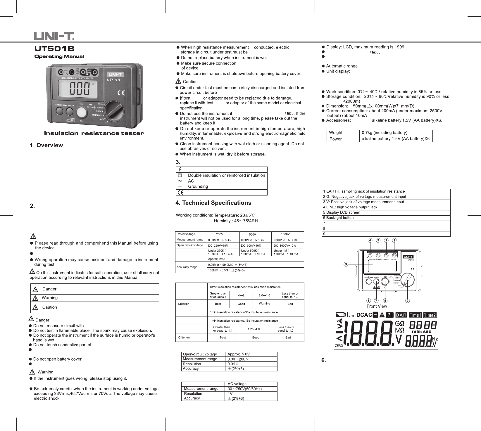
5. Tester's Structure(Front View)
measurement
for insulation resistance measurement
Switch button for PI/DAR
Test button
Rotary knob
When test leads are shorted and connected to the instrument, do
not press TEST key.
Do not touch the tested line during insulation measurement.
Eg: the instrument damaged or had exposed metal.
test leads lead when measuring.
during test.
Low Resistance Measurement
Voltage Measurement
LCD Display
Buttons and Rotary Knob
1. PI/DAR button: measures polarization index/dielectric absorption
ratio.
2. ZERO/LIGHT button: turns on/off the backlight or resets the
display to zero for low resistance measurement.
3. TEST button: turns on/off insulation and low resistance
measurement.
4. Rotary knob set to ACV: to measure AC voltage.
Page 2
P/N:110401107221X DATE:2018.06.26 REV.3
5. Rotary knob set to CONTINUITY: to measure low resistance.
6. Rotary knob set to 250V/500V/1000V:
to select test voltage for insulation resistance measurement.
If low battery indicator shows on upper left corner of LCD after the
meter is turned on, it means battery is almost used up and need to
be replaced.
Low battery indicator
(See Figure 3)
Dielectric absorption ratio measurement
Under insulation measurement mode, press PI/DAR button two
times to select DAR parameter, the screen displays Time 1(30s)/
Time2(1min), then press TEST to start DAR measurement, then
press TEST three times to select another DAR, the screen shows
Time 1(15s)/Time2(1min), press to begin another DAR
measurement.
(See Figure 5)
(See Figure 1)
Figure 1
(1) Set the rotary switch to ACV.
(2) Insert the red test lead into "V" jack and the black test lead
into "G" jack.
Please take extreme caution in order to avoid electric shock when
measuring high voltage.
Disconnect test leads and tested circuits and remove test leads
away from input jacks after completing the measurement.
R
lead
under test.
With the instrument connected to tested circuit as described above,
M
test probe with the circuit
(See Figure 2)
lead
Figure 3
B
(See Figure 4)
Figure 4
then switch to any insulation measurement range,
Do not short-circuit the test leads under high-voltage output status
or make insulation measurement after high voltage has already
been output.
●
Turn the knob to select test voltage 250V/500V/1000V.
lead
With the knob already set to test voltage 250V/500V/1000V, then
press TEST button,the instrument will be self-locked to measure
continuously. The test voltage will be output and TEST button will
light up. With the measurement finished, press TEST button to
unlock and stop the measurement.
figure 4,
lead
when replacing battery.
wires
Figure 5
batteries
installing the
the knob set to
Cleaning the housing
Clean the instrument surface with soft cloth or sponge
dampened with clean water.
To avoid damage to the instrument, do not submerge it into
the water.
When it is necessary to verify or repair instrument, please
deliver the instrument to qualified professional serviceman
or designated repairing department.
*END*
Figure 2
When red and black clips are connected to the circuit under test,
high voltage is output from LINE jack and the current from
EARTH jack.
Under insulation measurement mode, press PI/DAR button once
to select PI parameter, the screen displays Time 1(1min)/Time2
(10mins), then press TEST to start PI measurement.
 Loading...