

Page 1

1
UT361/UT362 OPERATING MANUAL
Table of Contents
Title Page
Overview
Unpacking Inspection
Rules For Safety Operation
The Anemoscope Structure
Display Symbols
Setting Up The Anemoscopes
Using The Anemoscopes
Measuring Wind Speed
Computer Connectivity (For UT362 only)
Maintenance
Technical Specification
2
3
4
7
8
14
16
21
23
24
27
Page 2

2
UT361/UT362 OPERATING MANUAL
Overview
Model UT361 and UT362 are an anemoscopes with high accurate sensitive resistance
(NTC) as testing point. For fan axis, it uses a high durable ruby shaft in order to
provide the accurate and stable measurement. It also comes with 8 digits chip to
conduct the digital mode and double display (VEL + Temperature, Flow + Area)
Model UT361 and UT362 come with the real time wind speed measurement, including
m/s, km/h, ft/min, MPH, KNOT, CFM, CMM as measuring units. In addition, it can
provide maximum value, minimum value, average value record, Centigrade temperature
and Fahrenheit temperature.
For data storage record, the maximum is 2,044 records capability. In sync, it can
provide auto switch down and continuity use functions.
Model UT362 can work with the computer to conduct the real time wind speed, data
transmitting storage and analysis as well as printing purpose.
This Operating Manual covers information on safety and cautions. Please read the
relevant information carefully and observe all the Warnings and Notes strictly.
Page 3

3
UT361/UT362 OPERATING MANUAL
Item
1
2
3
4
Description
English Operating Manual
USB Interface Cable (UT362) only
Software (UT362) only
9 V Battery Software
Qty
1 piece
1 piece
1 piece
1 piece
Warning
To avoid electric shock or personal injury, read the "Rules for Safe Operation"
carefully before using the Anemoscope.
Unpacking Inspection
Open the package case and take out the Meter. Check the following items carefully
to see any missing or damaged part:
Page 4

4
UT361/UT362 OPERATING MANUAL
In the event you find any missing or damage, please contact your dealer immediately.
In this manual, a Warning identifies conditions and actions that pose hazards to the
user, or may damage the anemoscopes or the equipment under test.
A Note identifies the information that user should pay attention to.
Rules For Safety Operation
Warning
Before using the anemoscopes inspect the case,do not use the anemoscopes if it is
damaged or the case (or part of the case) is removed. Look for cracks or missing
plastic
Pay attentions to the insulation around the connections.
Page 5

5
UT361/UT362 OPERATING MANUAL
To avoid possible electric shock or personal injury and to avoid possible damage to
the anemoscopes or to the equipment under test, adhere to the following rules
Do not use your hand to touch the fan and / or the measurement of wind count
and temperature portion
Replace the battery as soon as the battery indicator appears
If anemoscopes is in abnormal function stage, please stop to use it and sent it
your nearby service center for the further investigation.
Before using the anemoscopes inspects the case, do not use the anemoscopes
if it is damaged or the case (or part of the case) is removed. Look for cracks or
missing plastic. Pay attentions to the insulation around the connections.
Do not use the anemoscopes in an environment of explosive, humidity , inflammable.
The performance of the anemoscopes may deteriorate after dampened.
Page 6

6
UT361/UT362 OPERATING MANUAL
Use the specific authorized replacement part if you need to repair the anemoscopes
Do not use the anemoscopes if the opening the housing cover
Note the battery " + " and " - "pole when battery insert.
Followings are the condition which cause anemoscopes damages. Please carefully
use it to avoid any unit damage
Select the appropriate wind speed before use, it may avoid to load wind speed
(0 ~ 30 m/s), under the unknown scenarios.
Select the temperature meaning in 0 to 40 in order to avoid any fan damage
caused by the high temperature.
Do not try to recharge the battery.
Page 7
UT361/UT362 OPERATING MANUAL
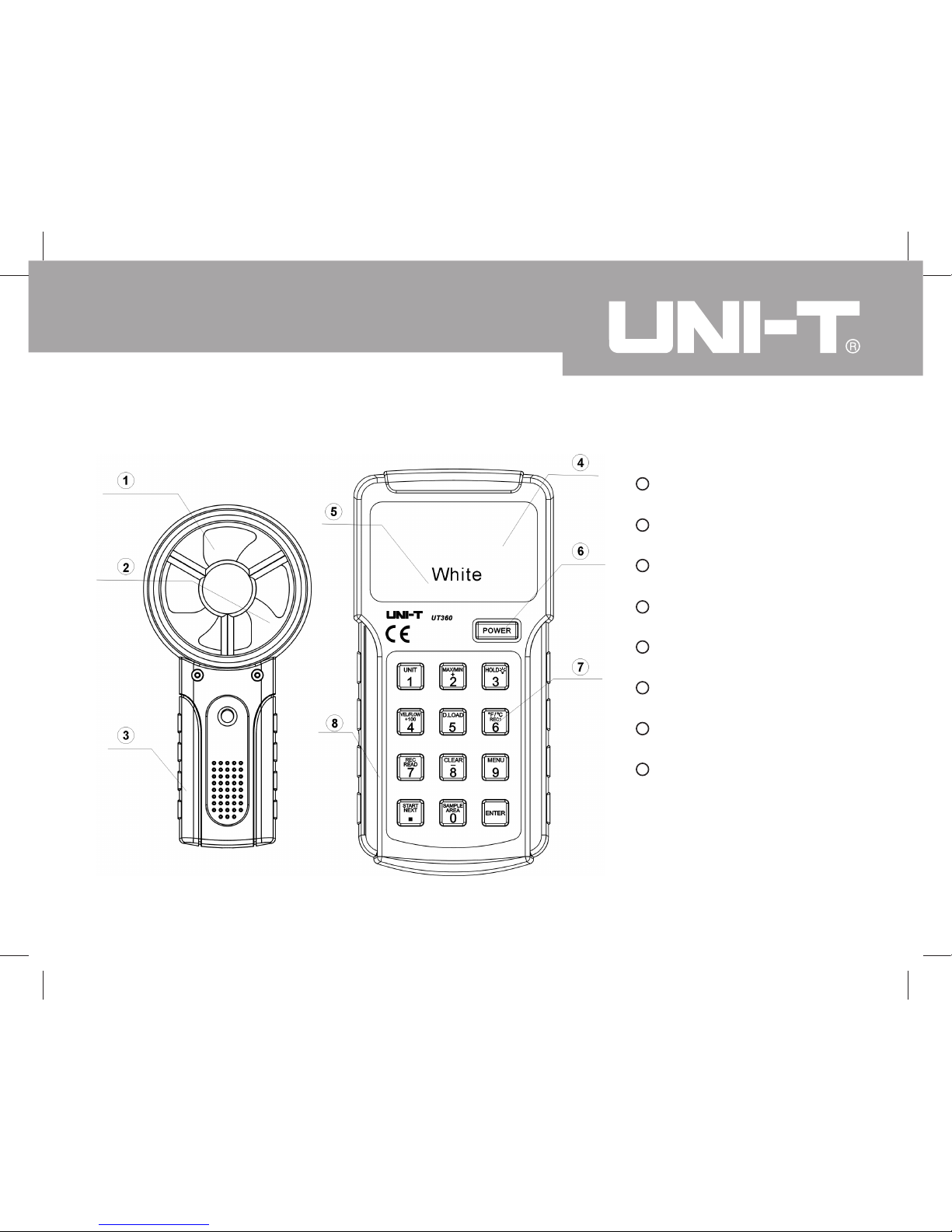
The Anemoscope Structure (see figure 1)
Fan
Wind Speed Indicator
Handle
Secondary Display
Primary Display
Power Button
Operational Button
Main Unit
1
2
3
4
5
7
6
8
Figure 1
7
Page 8
8
UT361/UT362 OPERATING MANUAL
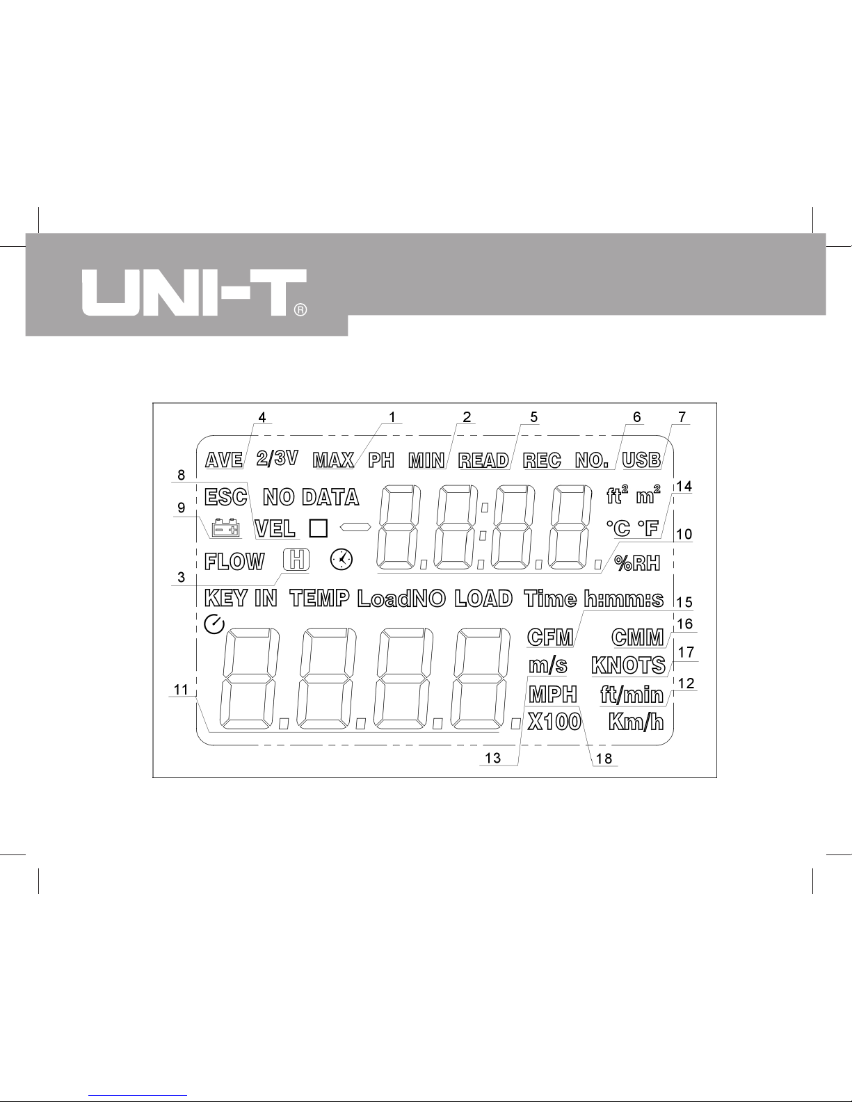
Display Symbols (see figure 2)
Figure 2
Page 9
9
UT361/UT362 OPERATING MANUAL
Functional Signs
Below table indicated for information about the functional sign operations.
Number
1
2
3
4
5
6
7
8
9
Sign
MAX
MIN
AVE
READ
REC NO.
USB
VEL
Meaning
Display of Maximum Reading
Display of Minimum Reading
Data Hold is on
Display of Average Reading
Display of Data Storage Measurement Reading
Display of Data Storage
USB is on
Wind Speed Measurement
The battery is Low
Page 10

10
UT361/UT362 OPERATING MANUAL
Number
10
11
12
13
14
15
16
17
18
Meaning
Secondary Data Display
Primary Data Display
Wind Speed Unit - Foot Per Minute
Wind Speed Unit - Meter Per Second
Fahrenheit Temperature Signal / Centigrade Temperature Signal
Cubic Feet Per Second
Cubic Meter Per Minute
Knots Per Hour
Miles Per Hour
Sign
ft/min
m/s
/
CFM
CMM
KNOTS
MPH
Page 11

11
UT361/UT362 OPERATING MANUAL
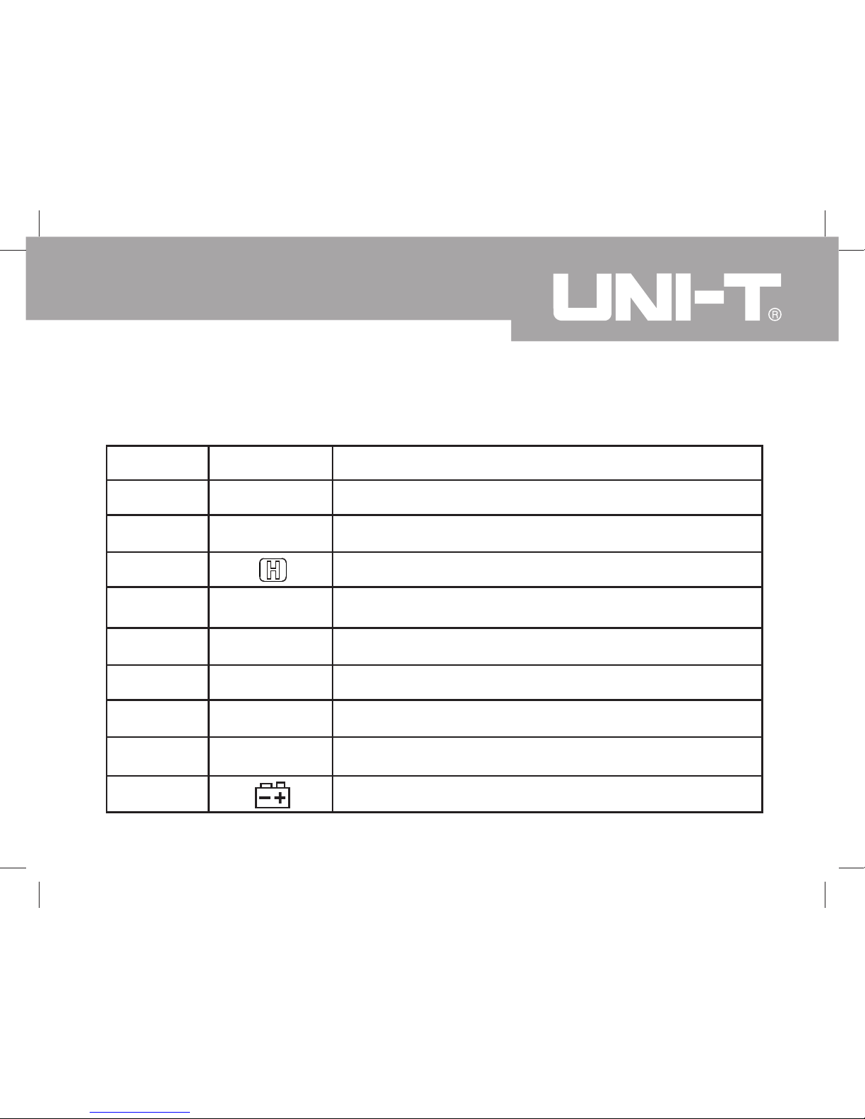
Display Symbols (see figure 3)
Figure 3
Function Key Description
Power on / Power off Button
Button 1 - This button
function key switch is for wind
speed measurement and
wind count measurement.
During wind speed
measurement, press "UNIT"
button m/s ft/min
KNOTS Km/h MPH
and vice versa.
During wind count
measurement, press "UNIT"
button CMM CFM and
vice versa.
Page 12

UT361/UT362 OPERATING MANUAL
12
Button 5 - Display the data download to USB port (For UT362 only)
Description
Button 2 - Press this button to choose
In wind speed measurement: maximum reading, minimum reading
and the instant measuring unit exchange
In wind count measurement: maximum reading, minimum reading,
average reading, 2/3V maximum value and instant measurement
units exchange. It can add together in the setup stage
Button 3 - Press once to enter the Hold mode. Press it again to
exit Hold mode. Continually press to open backlight display
Button 4 - Press this button to read 100 pieces of data records and
function switch on between wind speed measurement mode and
wind count measurement mode
Button 6 - This button function key switch is for Centigrade
temperature and Fahrenheit temperature
RELC1 means in data processing as you can view it from first data
Function Key
Page 13

13
UT361/UT362 OPERATING MANUAL
Function Key Description
Button 7 - Press this button to activate the REC feature. Press and
Hold this button to access data reading from database
Button 8 - Press this button to erase the data records before power
on. The data reduction shows on the database as well
Button 9 - It is a functional menu button. Press and Hold it to conduct
wind speed setting
Button Start / Next - Press Start to mean the first decimal point
input. Press Next to mean next decimal point during area input and
wind count measurement
Button Sample Area - Measurement in area setting
Button Enter - Confirmation key. See User Setting Stuff
Note: Under the button 1-9, it is under the area 0.000 ~ 9999 range of the wind count
measurement
Page 14

14
UT361/UT362 OPERATING MANUAL
Setup up the Anemoscopes
Press and hold button 9 (menu) to select feature setup. Press next button to go next
feature sub-menu.
A. USB setup
Press button 8 from USBO USB1. Then set up is as the opening default
B. Auto Switch Down
Press button 8 from AP00 AP01 and store in after power off. The default keep it
and need to reset when power on.
C. Auto Record
"REC" display on the LCD with the auto recording time between 0.5 ~ 255 seconds.
Press button 2 to extend auto recording time at the bottom of the LCD. Press button
8 to reduce auto recording time. Press and hold button to store in after power off.
Page 15

15
UT361/UT362 OPERATING MANUAL
This default keep it and no need to reset when power on.
D. Master Reset
LCD shows the DEF with flash. You can reset your anemoscopes to the factory settings.
Press button 2 of to the factory settings for USBO, APO1, 60S data clearing. Press
button 9 (menu) to cancel the factory setting. Then enter wind speed measurement
Page 16

16
UT361/UT362 OPERATING MANUAL
Using the Anemoscopes
Power On: Press "Power " button for a while to switch the anemoscopes on
Wind Speed and Wind Count Feature Switch: Press VEL / FLOW button. VEL
(wind speed) to FLOW (wind count)
Data Hold: Press " Hold " button to data capture, then press again to cancel the
data capture feature.
Wind Speed Measuring Unit Switch: Under the wind speed measurement, press
" UNIT " button m/s ft/min KNOTS Km/hr MPH in order to random to
have the measuring unit switch.
Wind Count Measuring Unit Switch: Under the wind count measurement, press
" UNIT " button CMM CFM to have the measuring unit switch.
Page 17

17
UT361/UT362 OPERATING MANUAL
Wind pipe input area:
1) Correct input the wind pipe area before wind count measurement
2) Set default area is one square meter after the entering wind count
measurement.
3) Select the approiate wind count-measuring unit. The press " Sample " button
to enter area input. LCD shows KEYIN blank on the top.
4) Enter the data and four digits value, then LCD will be manipulated it a new
display on the top
Example:
Enter 1, 0, 0, 0 Mean 1000 LCD display " 1000 "
Enter 1, ., 0, 0, 0 Mean 1.000 LCD display " 1.000 "
Enter 1, ., ENTET Mean 1.0 LCD display " 1.000 "
Page 18

18
UT361/UT362 OPERATING MANUAL
Enter 1, ENTET Mean 1 LCD display " 1.000 "
Enter 0, 0, 0, 1 Mean 0001 LCD display " 1.000 "
Enter ., 0, 0, 1 Mean . 001 LCD display " 0.001 "
... ... ...
In one area, it will probably to have a different input methods
but finally it has one display: Data Input Range: 0.000~9999
Temperature Measuring Unit Switch: Under the wind speed measurement, press
" / " button and vice versa
Maximum Wind Speed, Temperature: Under the wind speed measurement, press
" MAX/MIN " button Normal MAX and vice versa
Maximum, 2/3, Average Wind count: Under the wind count measurement, press
" MAX/MIN " button Normal MAX AVE and vice versa
Page 19

19
UT361/UT362 OPERATING MANUAL
Data Storage Functions:
1) LCD display " No Data " if no data storage
2) LCD display " Time " if database is full and cannot store any data in the
current time.
3) Manual data storage: press button 7 to display the automatic data storage
in LCD, also LCD displays REC and around 0.5 seconds to disappear " REC
"signal. Then press button 7, the data store in next position.
4) Automatic data storage: press button 7. LCD display " REC " and resume
it if press button 7 again (Fast press button 7 twice). Then enter automatic
data storage REC signal flash appear. Press the setup menu - automatic
data storage. In case of full data storage, it exits the automatic data storage
features.
Page 20

20
UT361/UT362 OPERATING MANUAL
5) Record Clearing
Method 1: Press and hold button 8 until LCD appear CLR when power on.
Method 2: Resume to factory setting (see function setting stuff)
Press and hold button 7 to view the data records of wind speed measurement and
wind count measurement.It automatically display last data record. LCD will be displayed
the recording number or recording data. LCD display " RECNO "
1) Press button 2 to increase the reading records. Press and Hold to
automatically increase the reading records
2) Press button 8 to reduce the reading records. Press and Hold to
automatically reduce the reading records
3) Press button 4 to increase 100 pieces of records (when the database
is large to use). The maximum record is 2044.
4) Press and hold button 7 to quite the database records module.
Page 21

Screw
Wind
Figure 4
Measuring For Wind Speed (Wind Count) (see figure 4)
Note: before use, the wind speed is over 10m/s under 1 - 2 minutes duration.
To carry out anemoscopes, follow the following
procedure:
1. Press on " Power " button until the
anemoscopes on
2. Press VEC / FLOW (figure 4) to conduct
function switch. LCD shows either " VEL "
or " FLOW "
3. Press Button 1 (UNIT) to conduct
measuring unit switch.
21
UT361/UT362 OPERATING MANUAL
Page 22

22
UT361/UT362 OPERATING MANUAL
4. Use figure 4 to conduct wind speed measurement , it shows wind flow direction,
but bear in mind Warning do not use it in opposite. A screw can fix on it.
(Note: UNI-T will not provide this screw to the customer, the customer need to buy it
separately)
5. Wait for 2 seconds to obtain a more precise reading during the connection
between wind speed measurement and wind source.
6. Obtain a more precise reading; you should move the anemoscope on at least
20 angle degrees in order to get more accuracy.
7. When the measurement of wind speed and wind temperature in parallel, the
secondary display show wind temperature value.
8. Press " / " (button 6) to conduct temperature unit selection, namely,
Centigrade Temperature and Fahrenheit Temperature.
9. The primary display show wind speed measurement value
Page 23

23
UT361/UT362 OPERATING MANUAL
Computer Connectivity (For UT362 only)(see figure 5)
When use the anemoscopes model UT362 need to connect USB cable with the
computer
Connect the USB interface cable, the anemoscope and the computer as reference
to the figure 5
Figure 5
White
Computer
Page 24

24
UT361/UT362 OPERATING MANUAL
Maintenance
A. Replacing The Battery
To avoid false reading, which could read to possible electronic shock or personal
injury, replace the battery as soon as the battery indicator " " appears.
To replace the battery
1) Turn the anemoscope off and remove all the connections from the
input terminals
2) Turn the anemoscope's front case down
3) Remove the screw from the battery compartment and separate the
battery compartment from the case bottom
4) Take out the old battery and replace with a new 9V battery (6LF22)
Rejoin the case bottom and the battery compartment and reinstall the screw.
Page 25

25
UT361/UT362 OPERATING MANUAL
5) Rejoin the case bottom and the battery compartment and reinstall the
screw.
B. Cleaning
Periodically wipe the case with a damp cloth and mild detergent. Do not use
abrasives or solvents.
C. Service And Repairing
This anemoscope is an auto calibration. Do not attempt to repair or service
your anemoscope unless you are qualified to do so and have the relevant
calibration, performance test, and service information
D. General Service
1) Periodically wipe the case with a damp cloth and mild detergent. Do
not use abrasives or solvents.
Page 26

26
UT361/UT362 OPERATING MANUAL
2) Take out the battery when it is not using for a long time.
3) Do not use or store the Meter in a place of humidity, high temperature,
explosive, inflammable and strong magnetic field.
Environmental Requirements
Operating Temperature Range: 0 ~50 ( 32 ~ 122 )
Relative Humidity: 0 ~75%, no condensation
Storage Temperature: - 20 ~ 65 ( - 4 ~ 149 )
Pressure: 500mB ~ 2 Bar
Safety/ Compliances:
Certification: EN61326: 2006
EN55022: 1998+A1+A2
EN55024: 1998+A1+A2
Page 27

27
UT361/UT362 OPERATING MANUAL
Range
2~10 m/s
10~30 m/s
UT362
(3%+0.5)
(3%+0.8)
UT361
(3%+0.5)
(3%+0.8)
Accuracy
Technical Specification
Wind Speed Measurement
Page 28

28
UT361/UT362 OPERATING MANUAL
Temperature Measurement
Temperature
Main Unit Temperature
Sensor Temperature
Range
0 ~40
32 ~ 104
0 ~40
32 ~ 104
UT362
3
4
3
4
UT361
3
4
3
4
Accuracy
** END **
Page 29

29
UT361/UT362 OPERATING MANUAL
This operating manual is subject to change without notice.
Page 30

30
UT361/UT362 OPERATING MANUAL
 Loading...