

UNI-T UT33B, UT33C, UT33D Operating Manual
UT33 B/C/D OPERATING MANUAL
UNI-T
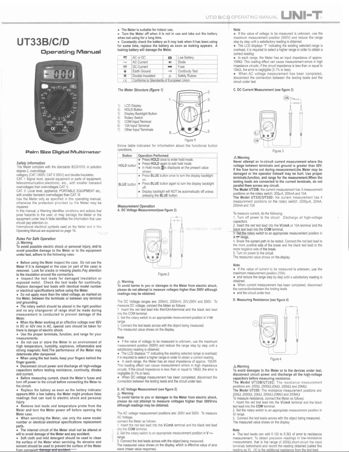
UT33B/C/D
Operating
Manual
Palm
Size
Digital
Mult
imeter
SafetyInformation
ThisMetercomplies
with
thestandards IEC61010:in pollution
degree2, overvoltage
catego
ry(CAT
1600
V,CAT II300V)and
double
insulatio
n,
CAT.
I: S
ignal
level,special
equipme
ntorpartsofequi
pmen
t,
tele
communication
,electronic, etc., with smaller transient
overvoltages
than
overvoltages
CAT.
II.
CAT
. II:
Loca
l level,
appliance, POR
TABLE
EOU
EHT
ele.,
with
sma
ller
transient
overvoltages
than
CAT.
IU
Usethe Meter only as specified in this opera'
otherwise the protection provided by the e
Sf
impaired.
Inthis
manual
, aWamingidentifies con
ditions
and
aclioos
pose
hazards
to the user, or may damage the er or
equ
ipment under
test.A
Note identifies
thei
nfonnation
Ihal user
s
houl
d pay
attent
ionon.
I
ntemat
ional
electrica
l symbols
used
onthe Meter andinthis
Ope
rating
Manualare
explai
nedon
pege
10.
RulesFor Safe
Operation
.<!>
Waming
Toavoidpossibleelectric shock or
persona
• to
avoid possible
damage
to the Meter or to the equipme
undertest,
adhere
tothefollowingrules:
• Before usingtheMeter inspectthecase. Donot usethe
Meterif it is
damaged
or the case (or part of the case)is
re
moved
. Lookforcracksor missing plastic.Payattention
totheinsulation
around
theconnectors.
• Inspect the test leads for damaged insulation or
exposed metal. Check the test leads for continuity.
Rep
lace
damaged
testleadswithidentical model number
or electrical specificationsbeforeusing
the Meter.
• Donotapplymorethanthe ratedvoltage. as
marlted
on
the Meter,
between
the terminals or
between
any terminal
andgrounding,
• Therotaryswitchshouldbeplacedin therightposition
and no any changeover of range shall be made during
measurement is conducted to prevent damage of the
Meter
.
• WhentheMeterworltingataneffectivevoltageover 60V
in DCor
42VrmsinAC, special careshould be takenfor
thereis dangerof electricshock.
• Usethe properterminals, function, andrangefor your
measurements
.
• Do not use or store the Meter in an environment of
high
temperature
, humidity, explosive, inflammable and
strong magnetic field.The
performance
of the Metermay
deteriorateafter
dampened
.
•
When
usingthetest
leads,
keepyourfingersbehindthe
fingerguards.
• Disconnect
circuit poweranddischargeallhigh-voltage
capacitors before testing resistance, continuity, diodes
andcurrent.
• Before
measuring
current,checkthe Meter's fuses and
tumoff powerto thecircuitbefore
connecting
theMeterto
the circuit.
• Replace the battery as soon as the battery indicator
appears.Withalowbattery,the
Meter
mightproduce false
readings that can lead to electric shock and personal
injury.
•
Remove
test leads and temperature probe from the
Meter and turn the Meter power off before opening the
Metercase,
•
When
servicing the Meter, use only the samemodel
numberor identical electricalspecificationsreplacement
parts,
• Theinternal circuit of the Metershall not beattered at
willtoavoid
damage
oftheMeterandanyacelde
• Soft cloth and mild
detergen
t should be used to
de
the surface of the
Meter
when servicing. No abrasM! and
solventshould beusedto preventthesurfaceof
the Meter
fromcorrosion,
damage
andaccident.
• The eter
is suitablefor indoor use.
• Tum the Meteroff when it is not in use and take out the battery
whennot using for a long time.
•
Constantly
check the
battery
asitmayleakwhenit has
been
using
for sometime, replacethe batteryas soon as leaking
appears
. A
leaking battery will
damage
the Meter.
~
-
ACorOC
~
Low
Battery
ACCurrent
-+I-
Diode
ocCurrent
-
Fuse
•
Ear.h
Ground
>'1)
Continuity
Tes
t
a
llotilIe
Insulat
ed l!>
Safety
Ruless
cs
Con/orms
to
Standards
of Eu
NV
an Union
The
eter Structure(figure 1)
1)
2)
6
3)
DisDIav
Bad<IIchI
Button
4}
5)
6)
7)
F
igure
1
ss
once
enter m e.
• Press HOLD
agom
toexit hold
mode.
• In H<*lmode,l:Iis
displayde
anthe
present
value
shown .
•
Press
BLUE buttononceto tumthed
isplay backlight
on.
• Press
BLUE
button
again
totumthe
display
backlight
off.
• D
isplay backlight
willNOT be
automat
ically
offunless
pressing
the
BLUE button
.
indicated for information about the functional button
IBLUE
button
Me
asurement
Operation
A.DC
VoItage
asurement(seefigure2)
Figu
re2
.<!>
Warnin
g
To avoidharms to youor
damages
to the
Meter
fromelectricshock,
pleasedonot
attempttomeasurevoltages
higherthan
500V
although
readings may beobtained.
The
DC
Voltage
ranges are:
200mV, 2000m
V, 20V,200V and
soe
v To
measml
OC •
conn
ecttheMeter asfo
llows
:
1.
Insert
the red testleadinto
theVQmAterm
inal
and
the
black
test
lead
intothe
COM
.
2. Settherotaryswtchkl an
appropri
ate
measurement
position
inV::=
r
ange
.
3.
Connect
theIeslleads
across
the objectbeing measured.
The
measured
:.ows
on
displa
y.
beobtained.
ValIagl'
lIl!aSlJrement
(see figure 2)
..,oId
hanm to you or damages to the
Meter
from electricshock,
The
AC
valage are:
200V
and
SOOV
. To
meas
ure
AC~
'
connect
the eteras
foIows
:
1.
lnsert
theredtestleadintothe VQmAterminal
and
theblacktest
lead
intotheCOMterm
inal.
2. Setthe
rota
ryswitch toanappropriate
measurem
entpositioninV-
r
ange
.
3.Connectthetestleadsacross
with
theobjectbeing
meas
ured
.
The
measured
value
showsonthedisplay,whichiseffective valueofsine
wave (mean value
response
).
Note
• If the
value
of voltageto be
measured
is
unknown
, usethe
max
imum
measurement
position (500V)and
reduce
the
range
stepbystep
until
asat
isfactory
reading isobtained
.
• The
LCD
displays
"1"indicating the
existing selected
range is
ove
rload
,itis
required toselect
ahigherrangeinordertoobtaina
correct
reading
.
• In each
range,
the
Meter
has an input
impedance
of approx.
10MQ.Thisloadingeffectcan cause
measurement
errors
inhigh
impedancecircuits.Ifthecircuit
impedance
isless
than orequal
to
1
OkQ
, theerrorisnegligible (0.1%or
less)
.
• When AC vollage measurement has been completed,
disconnect
the
connection
between
thetestingleadsandthe
circuit
under
tesl.
C.DCCurrent
Measurement
(seefigure3)
F
igure
3
.<!>
Warning
Neverattemptan in-circuit current
measurement
wherethe
voltagebetweenterminalsandgroundis greaterthan
60V.
If the fuse burns out during
measurement
,the Meter may be
damaged
or the operator himself may be hurt. Use proper
terminals
,function,andrangefor the
measu
rement.Whenthe
testing leadsareconnectedto thecurrentterminals, do not
parallel themacross anycircuit.
TheModel
UT33
B:the
curre
nt
measureme
nthas3
measurement
positions
onthe
rotary
switch:
200!
,A,2
00mAa
ndl
OA.
The Model
UT33C
IUT33D: the current mea
surement
has 4
measurementpositionson the rotary
switch:
2000,uA, 20mA
,
200mAand10A
To
measure
current, dothefollo
wing
:
1. Turn off powerto the circuit. Discharge all high-voltage
capaci
tors.
2.Insert thered lestleadintotheVQmAor lOA
terminal
andthe
black
testleadintotheCOMte
rmin
al.
3.-set
the
rotary
swi
tchtoan
appropriatemeasurement
posi
tionin
A
:=
range
.
4.
Brea
currentpathtobetested.
Conne
ctthe
red
test
lead
to
the
more
p<lSlIjW
side of the
break
andthe
black
testlead to the
more
negative
SIde
of break.
5.
Tum onpower
tothe cirtuil.
The
mea
sured
valueshows
onthe di
splay
.
Note
• If thevalue of current10 be
meas
uredis unk
nown,
usethe
maximumm
easurement
posit
ion(10A)
• andreducetherange stepby
step
until a
satis
factory
reading
is
obtained.
•
When
current
measurement
hasbeencompleted.d
isconnect
the
conneclionbetween
thete
sting
leads
• andthecircuit
unde
rtest.
D.
Measuring
Resistance
(seefigure4)
F
igure
4
.<!>
Warning
To avoid
damages
to the Meterorto the
devices
undertest,
disconnectcircuit power and dischargeall the high-voltage
capacitors
before
measuring
resistance.
The Model UT33B/UT33C: The resistance measurement
positions
are: 200Q,2000Q
,20kQ,
200kQ
and
20MQ
.
TheModel
UT33D
: Theresi
stance
meas
ureme
nt positionsare:
200Q,
2000Q
,20kQ,
200kQ
,20MQ
and
200MQ
To
measu
reresistance,
conne
ctthe
Meter
asfo
llows
:
1. I
nsert
the redtest lead intotheVQmA
terminal
and
theblack
testleadintotheC
OM
terminal
.
2.Setthe
rotary
switch
toanapp
ropriate
mea
surem
entpositionin
Q
range
.
3.
Connect
thetestleads
acro
sswiththeobjectbeingm
easured
.
The
measu
red
value
shows
onthe
display
.
Note
• The
testleadscanadd0.1Q to 0.3Q of errorto
resistance
eas
rement.
Toobtainprecision readings in low-resistance
measur
ement.
that is therange of 200Q.s
hort-ci
rcuit the input
term
inals
beforeh
andandr
ecord
the
reading
obtained(called
this
rea
dinaas
Xl.
(Xl
Istheadditional
resistance
from
thetest
lead
.
P/N:11040110248 0
UT33 S/
elD
OPERATING MANUAL
UNI-T
Then
usethe
equation
:
measured
resis
tance
value(Y)-(X) = precision re
adings
01
resistance
.
o For
high-resis
tance
measurement
(>1
MQ), it is nonnal
taking
several
secon
dsto
obtain astable
reading
.
o When resistance
measurement
has been completed,
discon
nectthe
connection
between
the
testing
leads and the
circuit
under
test.
E. DiodesandContinuity
Measur
ement(seefigure5)
Testing
Diodes
&>
Warning
To avoid
amages
to the Meter or to the devices under
test, disconnectcircuit powerand
discharge
all the high-
voltage
capacitors
beforediodes.
Usethediode test to check diodes,transistors, and other
semiconductor
devices.
The diodetest sends a current
through
thesem
iconductor
junction,andthenmeasuresthe
voltage
drop
across
the
junction.
A good silicon
junction drops
between
0.5V
and
0.8V.
Totesta
diode
0U1
ofaci
rcun,
connect
the Meteras
IoIows:
I. Insert the red testleadinto theVQmA t
erminal
and the
blacktest
lead
intothe
COM
terminal.
2. Setthe
rotary
switch
to
"*
(The
Mode
l:
UT33B
)Of
"*
,")
(The
Model:
UT33C
/UT33D
)
3. For
forward
voltage
drop rea
dings
on any
semi
conductor
component, place
theredtest
lead
onthe
component's
anode
and
place
the
black
test leadonthe
componen
t's
cathode
.
The
measured
value shows
onthe
display
.
Note
o In a circuit, a
good
diode
should
still p
roduce
a forward
voltage
drop reading of 0.5Vto 0.8V; however. r
else
voltage
drop
reading canvary
depe
ndingonthe
resislance
01
other
pathways betwee
n the probe tips.
o
Connect
thetestleadstothe
proper
tenrOnals
as said
above
toavoid
error display
.The
LCD
wi!
display
T
indicating
ooen-
circuit for wrong connection. The unit of diode is Volt IV),
displaying
the
positive
-connection
voltage-dropvalue.
o
When
diode
testing has
been
completed, disconnect
the
connection
between
thetesting
leads
andthecircuit
under
test
TheModel
UT33C
/UT33D
:Testingfor Continuity
Totestfor
continuny,connect
the
Mete
ras
below:
I. Inserttheredtest lead into theVQmA
tennina
l and the
black
teslleadintothe
COM
term
inal.
2.Set
the
rotaryswnch
to
"*
",)
.
3. Connect the test leads across with the object be'
measured.
The
buzzer
sounds
if the re
sistance
01
a
arwt
under Iesl .
less
than
70Q.
Note
o TheLCD displays "I" indi
cating
the
circuit
being
Iesled is
open
.
o
When
continui
tytesting hasbeen completed,lisalnned
connection
between
thetesting
leads
andthe
circuit
F.
ModelUT33C:Tempe
rature
easureme
(see gure 61
&>
Warn
ing
Toavoid harmsto you or
damages
to the Meter, se do
not attemptto input
voltages
higher than60Vin DCor
inAC,
The
Temperature
measuremen
t range is -40'C-
OOO
'Cor
40"F-
1832"F.To
measure
tempera
ture, c:onnecI as
follows:
1. Insert the redtemperature probeInIo the V
and
the
black
temperatu
reprobe inlo CO e
2.Setthe
rotary
swnch
to'C
Of"
.
3.
Place
the
temperature
probe
to the
oilled
beingmeasured
Themea
sured
value
shows
onthe
display
.
Note
o TheMeteraut
omatically
display
s the
temper
alure value
inside the Meter when there is no temperature probe
connec
tion.
o The included point contact temperature probe
can
onlybe
used
up to 250'C(482"F).For any
measureme
nt higher than
that.
therod
tvoe
temoerature
probe
mustbe
used
instead
.
•
When
temperaturemeasurement
hasbeencomp
leted, discon
nectthe
connection
between
thetestingl
eads
andthe
circuit
under test.
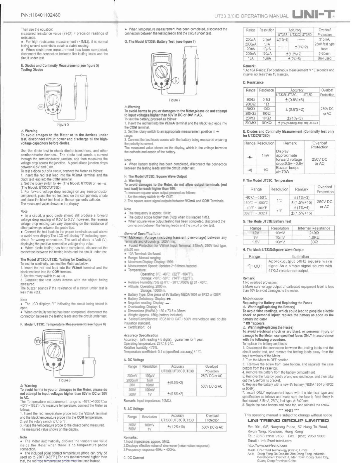
G. TheModel
UT33
B: BatteryTest (seefigure7)
Figure7
&>
To avoid nns toyouor
damages
tothe
Meter,please
donotattempt
to
1n1l'1ll., obges higherthan 60Vin DCor 30Vin AC.
To
proceedas
follows:
1.
rolaIy
VQrnA
terminal
and
theblacktest
leads
into
the
COM
appropria emeasurement
posi
tionin....
2. Set
range.
3.
Connect
Ill!
Ieslleads
across
the batterybeing
measu
red
ensuring
the
poIarBy
' rorrect
The
valle
shows
onthe
display,
w!lich
is the
voltage between
the
ca#Jode
and
anode
01the battery.
Nola
_PlY
....
m hasbeen
completed, disconnect
the
connection
be_en
'
:Ie
.!SlirlQ
leads andthe
circuit
under
test
terminals (red
Note
o The
o The
SClJllE!
3Vpp
wtlen it is loaded I MQ.
• 'MIen
square
wave
oo1put
tesllng
hasbeen
complet
ed, d
isconnect
the
comection
betweenIhe te
sllng
leadsandIhe
circuit
under test.
General Specifications
- . MaximumVoltage (includingtransient overvoltage) between any
3ls and
G.'Omding
'
SOO
Vrrns.
::>
Acroracy
Specification
Act:AJI'ac;.
(all.
reading
• b
guarantee
forI
year.
Operalllg Iemperaue; 23'C ± 5'C.
R
'.
<75
"-
" • cae ed
accu
racy)
f l ·C.
Ovenoad
Protection
2SOV
DCorAC
500V
DCorAC
ovencac
Prot
ection
SOOVDC
orAC
C. DC
Current
Range
Resolution
Accuracy
Overeat
Pro
tection
UT33B
UT33C I UT33D
200IlA
O.ll
l A
±(1%+2)
........
315mA,
250V
fast
type
fuse
:
5x20mm
2000IlA
IlIA
........
± (1%+2)
20mA
10pA
200mA 100pA
±(1.2%+2)
lOA 10mA
,!;(2%+51
Un-
Fused
Remark
:
I.At lOA
Range
: For
conti
nuousmeasu
rement
s 10
seconds
and
interva
l notlessthan 15
minut
es.
D.
Resistance
Range
Resolution
Accu
racy
Overeat
Protection
UT33BluT33CI UT33D
200Q 0.1Q
+ (0.8%+5)
250V
DC
orAC
2000Q
1Q
± (0.8%+2)
-1:(1
%+5)
20KQ 10Q
200KQ 100Q
20MQ 10KQ
200MQ
100
KQ
±[5%(reading·10}+10) UT33D
E.
Diodes
andContinuity
Measurement
(Continuity
test only
for
UT33C/UT33D)
Range Resolution Remark Overloaf
Protection
Display
*
I mV approximate
forward voltage 250V DC
drop:0.5v - 0.8v or AC
·OI
l
IQ
Buzzer beeps
at<70W
F.The Model
UT33C:
Temperature
Range Resolution Remark
Overloaf
Protection
-40 'C - 150'C + (1%+3)
250V DC
or AC
l
50 'C ~100 0 '
C
1'C
± (1.5%+15)
-'
IO"F -:102''!'
± (1%+4)
302"F
-
1832"F
1"F
± (1.5%+15)
G. The
Mode
UT33B
:Battery Test
I
Range Resolution
Internal Resistance
2V 10mV
240Q
9V IDmV 1.8KQ
I
1.5V 10mV 30Q
H. The
Mode
UT33D:Square
Wave
Output
Ranoe Illustration
Appr
ox.
outp
ut 50H z sq ua re
wave
...IJr-
OUT
signel.As a simple signal source with
47KQ resistance output.
Rema
rk:
I .Nooverloadprotection.
2
.Make
sure voltage
outpul
ofcalibratedequipment
level
is less
than
10Vtoavoid
damages
tothe
mete
r,
Maintenance
Replac
ing theBatteryandReplacingthe Fuses
&>
Warin
ing(Replac
ing the Battery)
Toavoidfalse
readings
,whichcould leadto possibleelectric
shockor personalInjury,
replace
thebatteryas soonas the
batteryindicator
" D "appears.
&>
Warining(Replac
ingthe
Fuses
)
Toavoid electricalshockor arc blast,or
personal
Injury or
damage
to the
Meter,
usespecifiedfuses
ONLY
inaccordance
withthefollowing
procedure.
To
replace
the
battery
and
fuses
:
I.
Oisconnectthe
connection
between
the
lesting
leads
andthe
cirCIJit
under test.and
remove
the
testing
leads
away
from
the
inputt
erminal
sof the
Meter
.
2 Tum
the Meierto
OFF
posit
ion.
3. Remove
the
screw
from
case
bottom
,and
separate
thecase
bottom
from
the
case
top.
4.
Rem
ovethebattery
from
the
battery
compartment.
5.
Remove
lhefusebyg
ently
prying
oneendloose, andthentake
oul the
fusefrom
its
bracket.
6.
Rep
lacethe
battery
withanew9V
battery
(NEDA
1604or
6F22
orOO6P)
.
7. Install
ONL
Yrep
lacement
fuses
Wit
h the identical typeand
specification asfollows
andmake
sure
thefuseis
fixed
firmly
in
thebra
cket.
315
mA,
250V,
fasl
type
,l' 5.20mm
8.
RejOin
the
case
bottom
and
case
top,
and
reinstall
thescrew.
••• END •••
This opeatingmanualis subjectto change withoutnolice
UN~TRENCGRCUPUMrrEC
Rm 901, 9/F, Nanyang Plaza, 57 Hung To Road,
Kwun Tong, Kowloon, Hong Kong
Tel:
(852) 2950 9168 Fax : (852) 2950 9303
Email:
info@uni·trend.com
hltp:llwww.unl-lrend.com
Made: Uni-Trend Tecnnology (
China)
limite
d
Add: Dong Fang Da Deo,Bel Zha Dong Fang Industrial
Development Oistriet,Hu Men Town,Dong Guan City.
Guang Dong Province ,China
 Loading...