

Page 1
Page 2

Title Page
I Overview 1
II Configuration 1
III Property 2
IV Instructions about product major components 4
V LCD Display 6
VI Select test method 8
VII Battery installation and check 10
VIII Power on and check battery status 12
IX Function operation instruction 14
X Maintenance 22
XI Warranty 24
XII Certificate 24
XIII Technical Index 25
Appendix: 27
Contents
Page 3

1 2
I Overview
Designed with artificial polarization piezoelectric effect, UT313/UT315
portable vibration meter apply to the normal vibration measurement of
mechanical equipment, especially vibration measurement of the rotating and
reciprocating machinery, widely used in industrial measurement such as
Machine Manufacturing, electric power and metallurgy etc.
II Configuration
home computer One piece
handle accessory machine One piece
9V battery One piece
English manual One
warranty card One piece
long probe One piece
short probe One piece
magnetic chuck One piece
III Property
LCD provides intuitive display of measurement value and measurement
status
Measurable acceleration, velocity, shift
Can select different vibration frequency property
Adopt high-sensitive probe with accurate measurement
Equip with a long and short probe, applicable to measurement in different
occasion
Page 4
3 4
Equip with a magnetic chuck, used to test when it is not convenient to hold.
Low electricity indication function
Automatic power-off function
LCD backlight function
Maximum value display function
USB communication function (only for UT315)
Data hold function
Data storage function
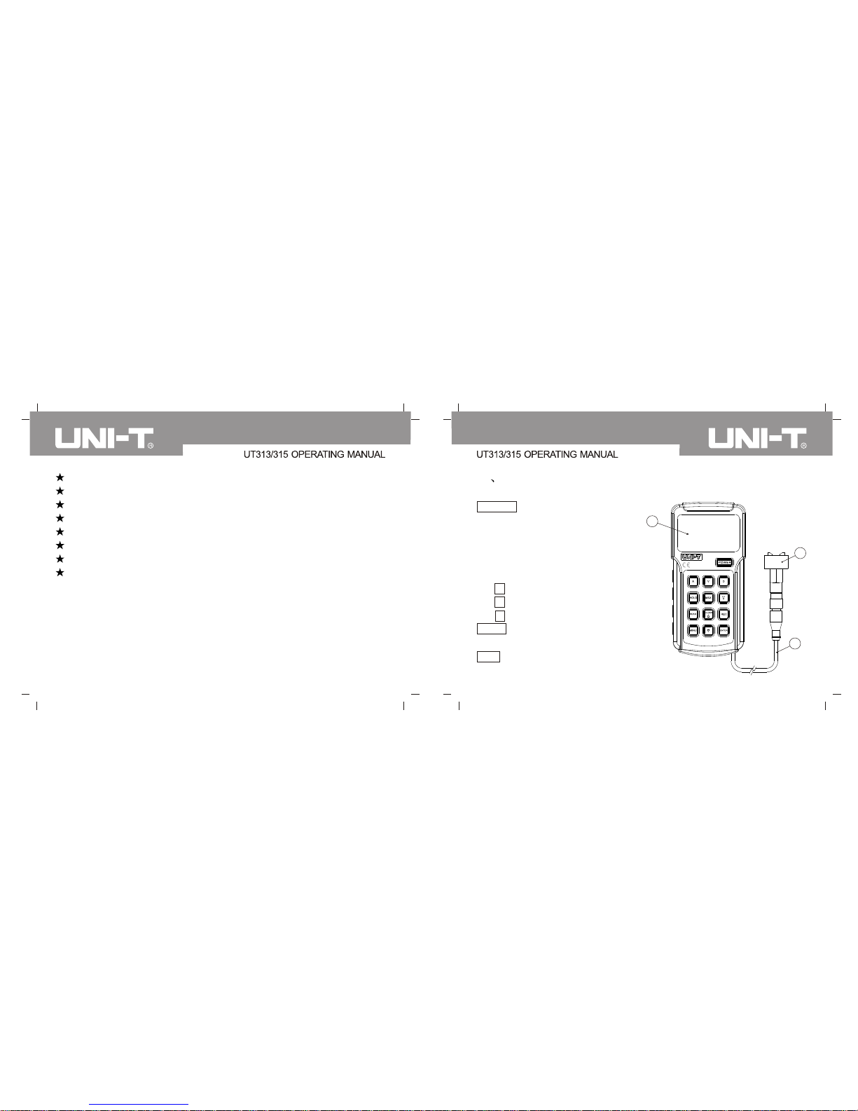
IV Instructions about product major components
power on, and keep pressing,
LCD will hold full display 1
second. Stop pressing, it starts
working, press key POWER
again to power off.
POWER key: press the key until
again to cancel holding data.
maximum value
Key A : Acceleration measurement
Key V : Velocity measurement
Key D : displacement measurement
HOLD key : HOLD data; press it
MAX key : MAX display the
1
2
3
Page 5
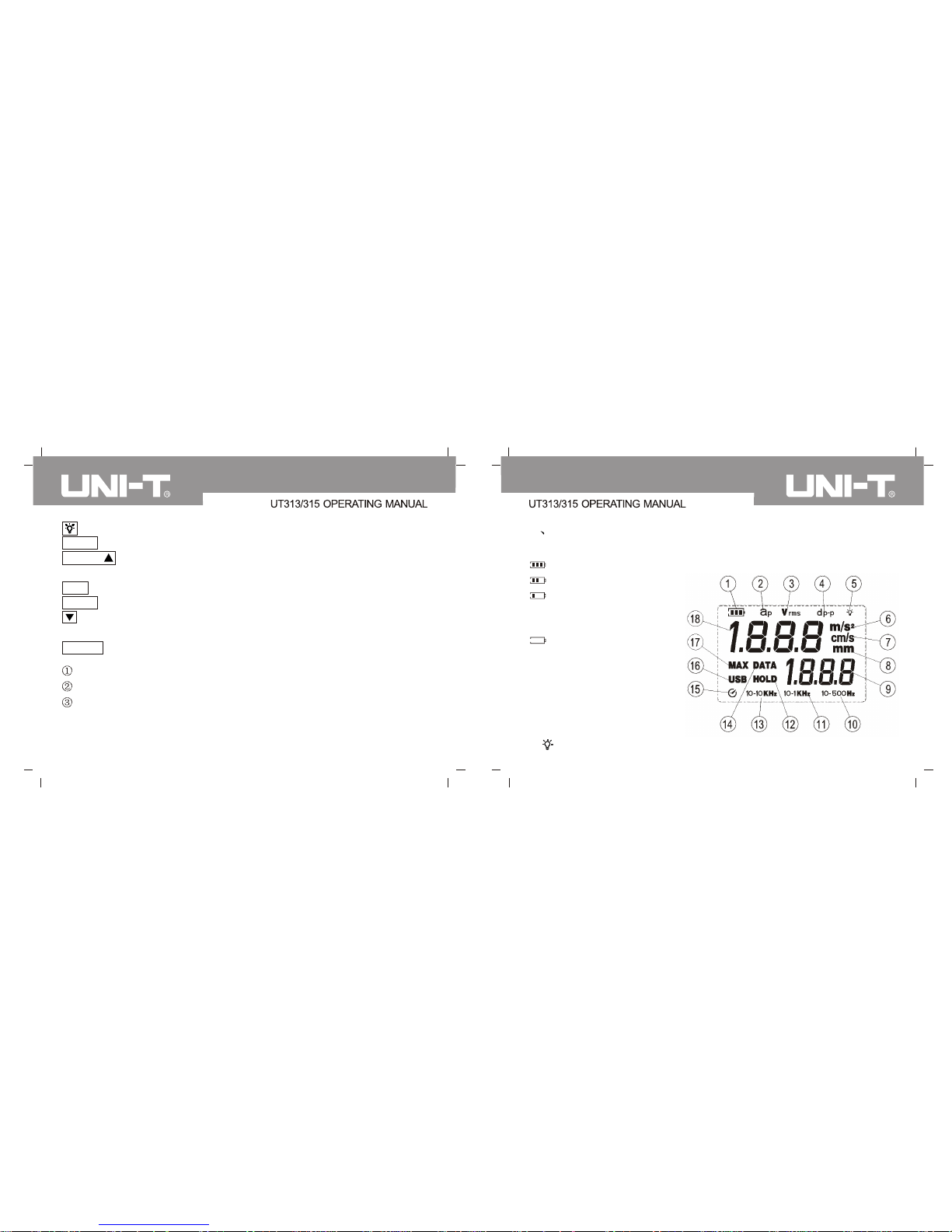
2. aP: acceleration indicator
3. Vrms: velocity indicator
4. dp-p: displacement indicator
5. : Backlight indicator
5 6
Key: open or close backlight
READ key: check record data
CLEAR/ key: Delete record data; data upturning, USB communication,
automatic power-off and storage time setting
REC key: data storage
MENU key: menu function set
key: Data down turning, USB communication, automatic power-off and
storage time setting
ENTER key: confirm
LCD (liquid crystal display)
Sensor connecting wire
Probe (long & short probe and magnetic suction pad for option)
V LCD Display
1. Battery symbol: indicates present remaining electricity. Four grades:
3 bars: sufficient electricity
2 bars: rather sufficient
1 bar: electricity will be
depleting, please replace
battery
Empty: electricity has
depleted, you have to replace
battery. The battery symbol
shall flicker.
Page 6

7 8
6. M/s2: acceleration unit indicator
In velocity measurement, LCD display the velocity unit m/s
7. cm/s: velocity unit indicator
8. mm: displacement unit indicator
9. Data record number display area
10. 10-500Hz: 10Hz-500Hz indicator
11. 10-1kHz:10Hz-1kHz indicator.
12. HOLD: reading hold measurement
13. 10-10kHz: 10Hz-10kHz indicator
14. DATA: data storage indicator
16. USB: USB indicator
17. MAX: maximum value measurement indicator
18. Measurement data value display area
15. : Automatic power-off function indicator
VI Select test method
Please select test method based on real status, four statuses:
1 Use short(s) probe to measure: it is installed with the machine and
applicable to wide scope vibration measurement; it can acquire effective
response numerical value, as shown in the following illustration
2 Use long (L) probe to measurement: it is an accessory in a package,
mainly used in rather narrow or special object area, with quick response,
as shown in the following illustration
Page 7

9 10
3 Use magnetic chuck to measure: it is an accessory in a package, mainly
used in plain area of iron objects, for instance, elevator etc. as shown in
the following illustration
4 Remove hardware probe to measure: used in plain object surface
measurement to acquire stable data, as shown in the following illustration.
VII Battery installation and check
Install battery:
Hold apparatus, press battery door with right thumb, open battery door from
the arrow-pointed direction, as shown in the following illustration.
Page 8

11
12
2 Put 9V (G6F22 6F22) battery into battery holder correctly, aware of
battery polarity and then close battery holder door, as shown in the
following illustration.
VIII Power on and check battery status;
1 Press POWER key to power on.
As shown in the following illustration:
Press down
Page 9

13
14
2 Press the key until LCD hold full display 1 second, stop pressing it to start
working with fault status being acceleration measurement mode, USB
failure to communicate and automatic power-off status; if LCD screen
displays symbol or , please replace battery timely as
shown in the following illustration.
Press POWER key to power off immediately.
IX Function operation instruction
1 Acceleration measurement:
1 Press key A to enter into acceleration measurement mode with fault
status being acceleration measurement mode m/s2 ,LCD screen shall
display aP; indicators of 10-10kHz and m/s2 are as follows:
2 Use probe to measure object according to the selected way and
measurement result shall display in data value display area of LCD
Page 10

15 16
as shown in the following illustration:
2 Velocity measurement:
1 Press key V to enter into velocity measurement mode and LCD screen
shall display Vrms; indicators of 10-1kHz and cm/s are as follows:
2 Use probe to measure object according to the selected way and
measurement result shall display in data value display area of LCD as
shown in the following illustration:
3 Displacement measurement:
1 Press key D to enter into velocity measurement mode and LCD screen
shall display dp-p; indicators of 10-500Hz and mm are as follows:
Page 11

17 18
2 Use probe to measure object according to the selected way and
measurement result shall display in data value display area of LCD as
shown in the following illustration:
4 Maximum value measurement
Under corresponding measurement mode, press key MAX to enter into
maximum value measurement mode, LCD screen shall display indicator of
MAX and results of maximum under corresponding measurement mode in
the data value display area; press key MAX to cancel maximum value
measurement.
7 Data storage:
Press key REC to enter into manual data storage mode, LCD screen shall
display indicator of DATA and store the present measurement value manually,
DATA signal shall disappear after about 0.5 second; press key REC to
conduct next position data storage. Press REC for a long time to enter into
automatic data storage mode, indicator of DATA on LCD screen shall flicker
continuously, and store the present measurement value automatically
5 Reading holds measurement:
Press HOLD key to enter into reading hold measurement mode, LCD screen
shall display indicator of HOLD and hold the present measurement value in
data value display area on LCD screen.
6 Backlight display:
Press the key to enter into LCD backlight display mode, and LCD
screen shall display indicator , and light up, press key to exit
backlight display.
Page 12

19
20
between the set time intervals (detailed in menu function set). If automatic
record count exceeds the maximum record count 1999, it shall exit data
storage automatically.
8 Check record data
Press key REND to enter into check record data mode, if no storage data,
data value on LCD screen display area display --- data record number
display area display --- and enter into test function after about 0.5 second.
If any storage data, it shall display the last data and record number; press
key to reduce record number and its corresponding storage data; Press
for a long time to automatically reduce them. Press key to increase
record number and corresponding storage data, press it for a long time to
increase them automatically. Press REC to display increase by 100, if record
count is less than 100 or exceed maximum record count 1999, it shall back to
the first record number and corresponding storage value; press REC to back
to the first record number and corresponding storage value. Under the mode,
only the above keys and can be used except for others. Press the key to
exit the mode.
9 Delete record data:
Method1: before start machine, press key CLEAR and POWER in the same
time, stop pressing key POWER until LCD screen display CLR, record
deletion has been completed.
Method2: restore factory setting (detailed in menu function setting)
10 Menu function set:
Press key MENU to enter into menu function set with fault status USB0,
which indicates failure to conduct USB communication, press key or to
change USB setting, LCD screen shall display indicator of USB and USB1
indicates being able to conduct USB communication; Under menu function
set mode, press key READ, LCD display USB1 flickering, after memory data
transmitted to computer, press key ENTER to save and enter into next menu
---set automatic power-off AP01, which indicates automatic power-off function
Page 13

21 22
indicating the automatic power-off function is off, then set AP01.
Press ENTER to save and enter into next menu to record interval
automatically, press automatic add for a long time or press key to reduce
time, press automatic subtraction, time scope of the machine can be set is
0.5-255;Press key ENTER to save and enter into next menu-factory set.LCD
displays DEF? (Press key ENTER to restore factory set USB0, AP01, 60S,
clearing all record data. If press key MENU, it will enter into the original
measurement function. Under menu set mode, if power-off, the menu status
shall be stored automatically and be restored from save status after power-on,
without reset each time).
is open, LCD shall display indicator , and press key or to set AP00,
Able to use short probe s to measure high/low frequency scope
vibration respectively.
Notes:
Long probe L is only applicable to low frequency measurement, when
measurement accelerated and frequency exceeds 1 kHZ, please replace
short probe to measure again.
It will be powered off automatically 3 minutes later if without any operation.
X Maintenance
1 Working environment: UT313/UT315 vibration meter is precision
apparatus required to avoid collision, shock, moisture, strong power,
magnetic field, oil and dust.
2 Replace battery and maintenance
1 in working, LCD screen shall appear symbol , user needs to
replace battery timely in reference to illustration in the manual.
2 please draw out battery to avoid battery weeping, which shall cause
severe damage to the apparatus if you needn't use the test apparatus for
Page 14

23 24
a long time.
3 Don't dismantle the apparatus or try to make any transformation interiorly.
4 Chassis cleaning: alcohol and diluents are erosive to chassis, especially
to LCD window, please
XI Warranty
1 As regard warranty clause, please refer to the provided warranty card.
2 Dismantle of product by user at his discretion, damage after purchase
resulted by improper use and altering of the warranty card and without
voucher may be excluded from such warranty coverage.
XII Certificate
Vibration certificate comply with the following standards:
EN61326-1:2006
Page 15

Battery electricity indication
Storage temperature scope
Working humidity scope
Battery life
Automatic shut-off
LCD backlight shut off time
Working current
Power-off circuit
Power supply
Display refresh period
LCD display
Measurement error
Displacement measurement scope
Velocity measurement scope
Acceleration measurement scope
Vibration collection
Technical parameter
25
26
10HZ ~ 500HZ
XIII Technical Index
Technical index
Piezoelectric accelerometer
0.01cm/s~19.99cm/s (true valid value)
0.001mm~1.999mm (peak peak value)
(5%+2dgts)
Acceleration measurement
frequency scope
10HZ ~ 10kHZ
Velocity measurement frequency
scope
10HZ ~ 1kHZ
Displacement measurement
frequency scope
3 1/2 bit digit display
1 second
9V alkaline battery
1uA
25mA
Press backlight key to shut off
Automatic shut-off after about 3
minutes of non-operation
20 hours of continuous use
Working temperature scope
050
20%RH 80%RH
-20 60
Battery voltage 7V, indicate low
voltage symbol
Dimension
Weight
Elevation
2000 m
0.1m/s ~199.9m/s (peak value)
2 2
Page 16

27 28
Appendix:
a. Mechanical Vibration Rating Table ISO2372
45
Vibration intensity
Applicable to the following machine
Vibration velocity Vrms(mm/s)
Notes:
1) Grade I is small-size electric motor (less than 15kW electric motor); Grade
II is medium-size electric motor (15kW-75kW electric motor); Grade III is
large original electric motor (hard base) ; grade IV is large original electric
motor (plastic base).
2) A, B, C, D is the vibration rating. A is great, B is satisfactory, C is discontent
and D is not allowed. The measurement velocity RMS value shall be on the
orthogonal intersection direction of shell bearing.
b. the maximum allowable vibration for electric motor higher than 1
horsepower NEMA MG1-12.05
3000~4000
25.4
1500~2999 38.1
1000~1499 50.8
63.6
Peak-peak displacement amplitude
Rotating speed
999
Page 17

d. Preformed winding squirrel-cage induction electric motor
50.8
63.6
38.1
50.8
25.4
25.4
Sync rotating speed
720~1499
1500~2999
3000
Peak-peak displacement amplitude ( m)
Plastic support
Rigid support
The standard is formulated by American Petroleum Institute.
29
30
Notes: for AC electric motor, use highest sync rotating speed; for DC electric
motor, use the maximum power rotating speed; and for serial and
multipurpose electric motor, use working rotating speed.
c. the maximum allowable vibration for large electric motor
NEMA MG1-20.52
Peak-peak displacement amplitude
Rotating speed
3000 and higher
25.4
1500~2999
999
50.8
1000~1499
63.6
76.2
The above two standard are formulated by National Electrical Manufacturers
Association (NEMA)
e. ISO/IS2373 the electric quality standard based on vibration speed amplitute
80<H<132 132<H<225 225<H<400
Quality grade
600~3600 1.8 2.8
4.5
N Normal
600~1800
1800~3600
0.71
1.12
1.12
1.8
1.8
2.8
600~1800
1800~3600
0.45
0.71
0.71
1.12
1.12
1.8
R Good
S Special
Rotating speed
Axis height H mm
maximum speed vibration rms(mm/s)
r/min
r/min
Page 18

31
Grade N limit value recommended in the table is only applicable to common
electric motor.
 Loading...