

Page 1

P/N:110401109062X
Page 2
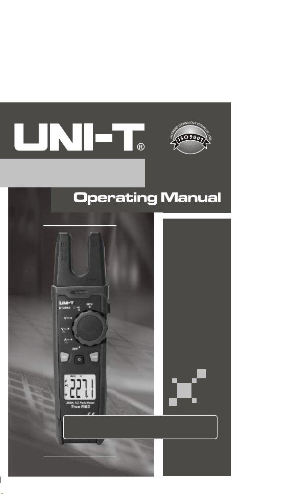
200A AC Fork Meter
UT256A
Page 3

Preface
Thank you for purchasing the new fork meter. In order to use
this product safely and correctly, please read this manual
thoroughly, especially the Safety Instructions part.
After reading this manual, it is recommended to keep the
manual at an easily accessible place, preferably close to
the device, for future reference.
Limited Warranty and Liability
Uni-Trend guarantees that the product is free from any defect
in material and workmanship within one year from the purchase
date. This warranty does not apply to damage caused by
accident, negligence, misuse, modification, contamination
or improper handling. The dealer shall not be entitled to give
any other warra nt y on be half o f Uni- Trend. If you ne ed
warranty service within the warranty period, please contact
your seller directly.
Uni-Trend will not be responsible for any special, indirect,
incidental or subsequent damage or loss caused by using
this device.
UT256A User Manual
2
Page 4

Table of Contents
I. Overview -------------------------------------- 4
II. Accessories ---------------------------------- 4
III. Safety Instructions ------------------------ 5
IV. Electrical Symbols ------------------------- 7
V. External Structure -------------------------- 8
VI. LCD Display -------------------------------- 9
VII. Function Buttons ------------------------ 10
VIII. Operating Instructions ----------------- 11
IX. Specifications ---------------------------- 17
X. Maintenance ------------------------------- 22
3 4
Page 5

I. Overview
The UT256A is a stable, safe and reliable 6000-count AC fork
meter. It measures AC current via the fork, AC/DC voltage
(up to 1000V), resistance, and continuity via test leads, and
can detect the presence of AC voltage via the non-contact
voltage (NCV) sensor. It has data hold, auto/manual range,
LCD backlight, audio/visual alarm, and flashlight functions.
The full-scale overload protection and unique appearance
desig n m ak e i t a special el ec tr ic al meter wi th su pe rior
performance.
II. Accessories
Open the package box and take out the meter. Please double
check whether the following items are missing or damaged.
1. User manual ----------------------------------------------- 1 pc
2. Test leads 1 pair ---------------------------------------------------
3. Cloth bag 1 pc ----------------------------------------------------
4. 2 pcs 1.5V AA batteries (preinstalled into meter) ---------
If any of the above is missing or damaged, please contact
your supplier immediately.
UT256A User Manual UT256A User Manual UT256A User Manual UT256A User Manual
Page 6

III. Safety Instructions
The meter is designed according to IEC/EN61010-1, IEC/
EN6 101 0-2-0 33 a nd EN6 132 6-1 sa fet y standar ds, and
conforms to CAT II 1000V, CAT III 600V, double insulation,
and pollution degree 2. Use the meter only as specified, or
the protection provided by the meter may be impaired.
1. Be fore use, ple ase check if there is a ny item which is
damaged or behaving abnormally. If any abnormal item
(such as bare test lead, damaged meter casing, broken
LCD, etc.) is f ound, or if the meter is consid ered to be
malfunctioning, please do not use the meter.
2. Do not use the meter if the rear cover or battery cover is
not covered up, or it will pose a shock hazard!
3. Before each use, verify meter operation by measuring a
known voltage.
4. Wh en using the m eter, keep fingers behi nd the finger
guards of the test leads, and do not touch exposed wires,
connectors, unused inputs, or circuits being measured to
prevent electric shock.
5. Place the function switch in the correct position before
measurement. It is forbidden to change the position during
measurement.
6. Do not apply more than the rated voltage, as marked on
the meter, between any meter terminal and earth ground
to prevent electric shock or damage to the meter.
7. Use caution when working with voltages above AC 30Vrms,
42Vpeak or DC 60V. Such voltages pose a shock hazard.
5 6
Page 7

8. Never input a voltage or current which exceeds the specified
limit. If the range of the measured value is unknown, the
maximum range should be selected.
9. Before measuring the resistance and continuity online,
switch off the power supply of the circuit, and fully discharge
all capacitors to avoid inaccurate measurement.
10. Whe n th e “ ” symbol ap pea rs on the LCD, ple ase
replace the batteries in time to ensure measurement
accuracy. If the meter is not in use for a long time, please
remove the batteries.
11. Do not change the internal circuit of the meter to avoid
damage to the meter or user!
12. Do not use or store the meter in high temperature, high
humidity, flammable, explosive or strong magnetic field
environments.
13. Clean the meter casing with a soft cloth and mild detergent.
Do not use abrasives or solvents!
UT256A User Manual UT256A User Manual
Page 8
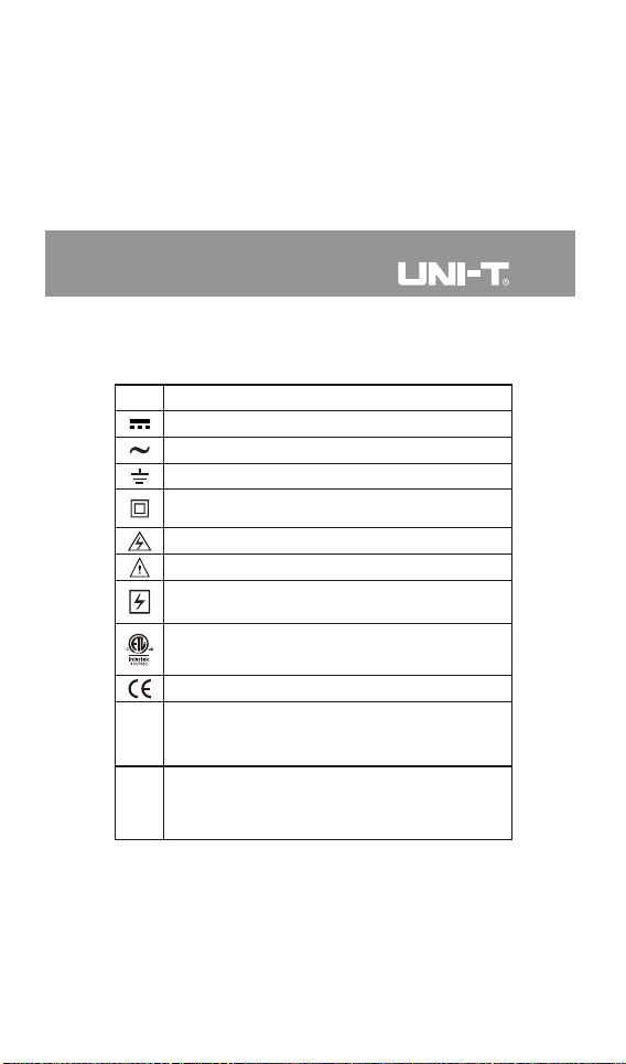
IV. Electrical Symbols
Symbol
Description
Direct current
Alternating current
Earth (ground) TERMINAL
Equipment protected throughout by DOUBLE INSULATION
or REINFORCED INSULATION
Caution, possibility of electric shock
Warning or Caution
Application around and removal from UNINSULATED
HAZARDOUS LIVE conductors is permitted.
Conforms to UL STD 61010-1, 61010-2-032, 61010-2-033.
Certified to CSA STD C22.2 No. 61010-1,
61010-2-032, 61010-2-033.
Complies with European Union standards
It is applicable to testing and measuring circuits
CAT II
connected directly to utilization points (socket outlets and
similar points) of the low-voltage MAINS installation.
It is applicable to testing and measuring circuits
connected to the distribution part of the building's
CAT III
low-voltage MAINS installation.
7 8
Page 9
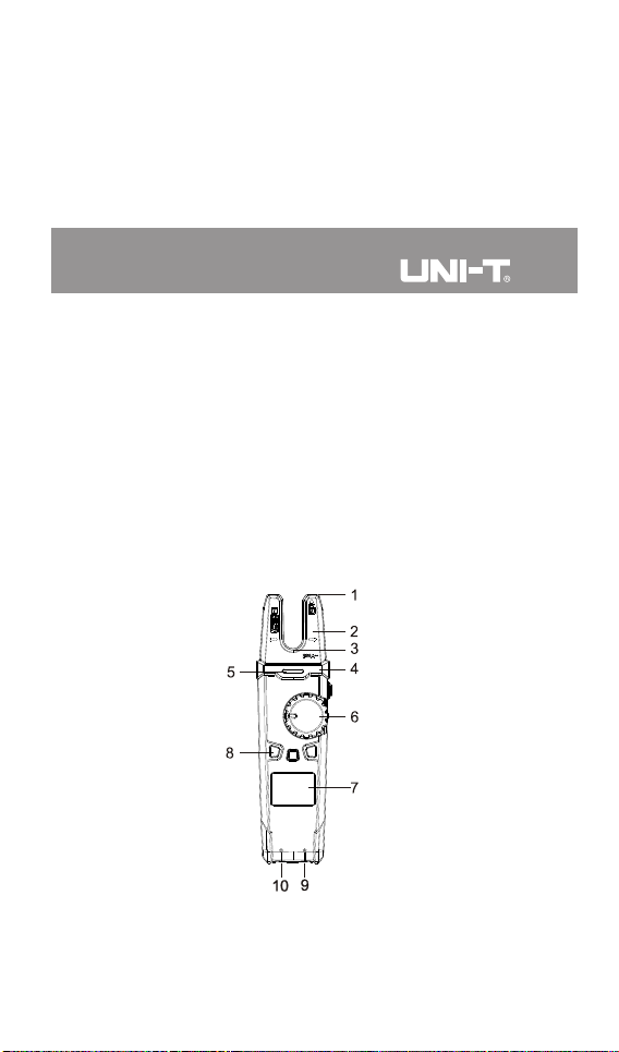
V. External Structure (Picture 1)
1. NCV sensor
2. Open jaw fork
3. Flashlight LED light
4. Hand guard
5. alarm indicatorVisual NCV
6. Function switch
7. LCD display
8. Function buttons
9. Signal input jack (red and positive +)
10.COM input jack (black and negative -)
Picture 1
UT256A User Manual UT256A User Manual
Page 10
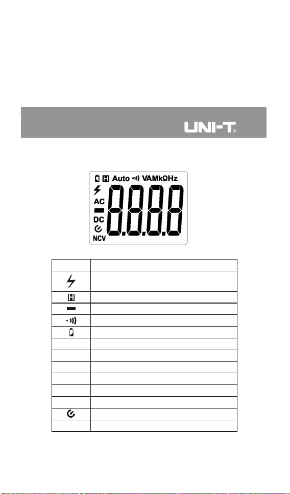
VI. LCD Display (Picture 2)
Picture 2
Symbol
AC/DC
Auto
Ω, kΩ, MΩ
V
A
Hz
NCV
Warning sign, indicating AC voltage >35V
and DC voltage >50V
Data hold
Negative reading
Continuity test
Low battery indication
AC/DC measurement
Auto range
Resistance units (ohm, kilo-ohm, meg-ohm)
Voltage unit (volt)
Current unit (ampere)
Frequency unit (hertz)
Auto power off
Non-contact voltage sensing
Description
9 10
Page 11

VII. Function Buttons
1.SELECT button: When the function switch is in the composite
function position, short press this button to switch between
the corresponding functions.
2.H/ button: Short press this button to enable/disable the
data hold function. Long press (>2s) this button to turn
on/off the flashlight.
3.RANGE button: Short press this button to enter the manual
range mode (no “Auto” displayed) and change the range
in this mode. Long press this butt on to exit the manual
range mode. Turn the function switch or restart the meter
to restore default settings.
4. button: Short press this button to turn on/off the backlight.
UT256A User Manual UT256A User Manual
Page 12
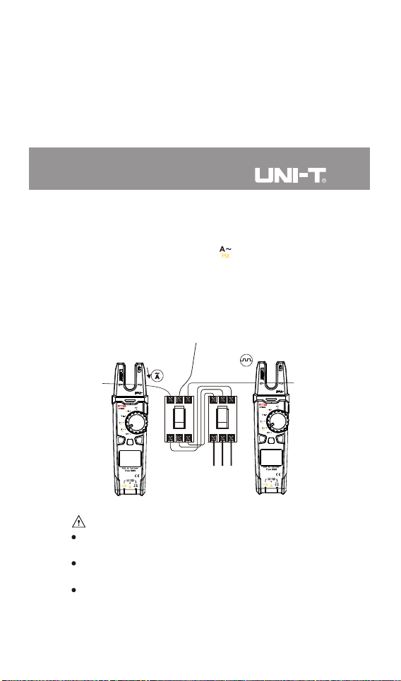
VIII. Operating Instructions
1. AC Current/Frequency Measurement (Picture 3)
1) Turn the function switch to the position, and use the
SE LEC T b utt on t o s wit ch t o AC c urr ent /f req uen cy
measurement.
2) Clamp one current-carrying wire and keep it at the bottom
of the U-type open jaw fork.
3) R ead th e meas ured valu e on th e disp lay (f requency
response: 50Hz~60Hz).
Picture 3
Caution:
Disconnect the test leads when measuring current to avoid
electric shock.
Do not place any part of your body beyond the hand guard
of the meter when measuring current.
The maximum measuring current cannot exceed AC 200A.
11 12
Page 13
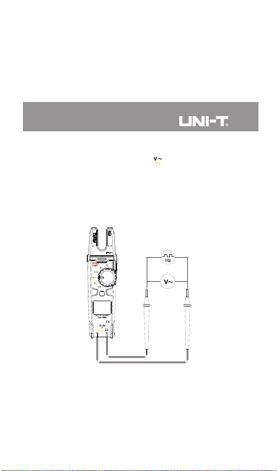
2. AC Voltage/Frequency Measurement (Picture 4)
1) Turn the function switch to the position, and use the
S EL E CT bu tto n t o sw itc h t o A C v olt age /f req ue n cy
measurement.
2) Insert the red test lead into the signal input jack, black
into the COM input jack, and make the probes in contact
with both ends of the measured object (part).
3) Read the measured value on the display.
Red Black
Picture 4
UT256A User Manual UT256A User Manual
Page 14
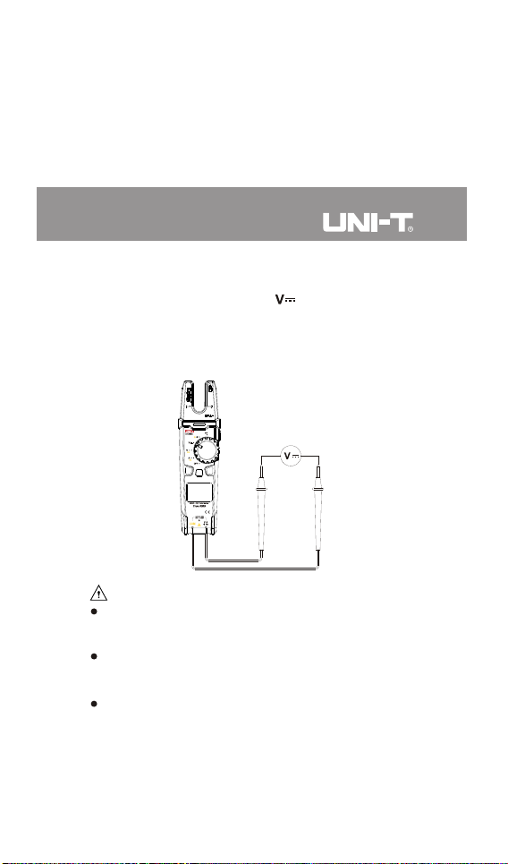
3. DC Voltage Measurement (Picture 5)
1) Turn the function switch to the position.
2) Insert the red test lead into the signal input jack, black into
the COM input jack, and make the probes in contact with
both ends of the measured object (part).
3) Read the measured value on the display.
Red Black
Caution:
Maximum measuring voltage: 1000V (AC/DC voltage)
under CAT II, 600V (AC/DC voltage) under CAT III,
ACV: 45Hz~400Hz.
Do not exceed the limits, otherwise there may be danger
of electric shock or damage to the meter (If the LCD displays
“OL”, it indicates that the voltage is over range).
The input impedance of the meter is 10MΩ. This load effect
may cause measurement errors when measuring highimpedance circuits. If the measured impedance is
≤ ≤ 10kΩ, the er ro r ca n be i gn or ed ( 0.1%).
Picture 5
13 14
Page 15
Be cautious to avoid electric shock when measuring high
voltages.
Before each use, verify meter operation by measuring a
known voltage.
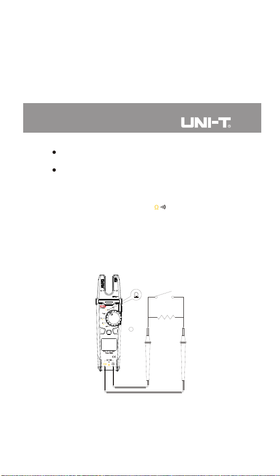
4. Continuity/Resistance Measurement (Picture 6)
1) Turn the function switch to the position, and use the
SELECT button to switch to continuity/resistance
measurement.
2) Insert the red test lead into the signal input jack, black into
the COM input jack, and make the probes in contact with
both ends of the measured object (part).
3) Read the measured value on the display.
Picture 6
Red Black
Continuity
Resistance
UT256A User Manual UT256A User Manual
Page 16
Caution:
Do not input voltages higher than DC 60V or AC 30V to
avoid personal injury.
Before measuring the resistance online, switch off the power
supply of the circuit, and fully discharge all capacitors to
ensure accurate measurement.
If the resistance is >0.5Ω when the test leads are short-
circuited, please check the test leads for looseness or other
abnormalities.
If the measured resistor is open or the resistance exceeds
the maximum range, the LCD will display “OL”.
Measure ment result = displaye d value – resistance of
shorted test leads
5. Non-contact Voltage (NCV) Sensing (Picture 7)
1) Turn the function switch to the NCV position, and use the
SELECT button to switch to high voltage measurement
(“EFHI”) or low voltage measurement (“EFLo”). When the
voltage is >48V, select “EFHI”; when the voltage is <48V,
select “EFLo”.
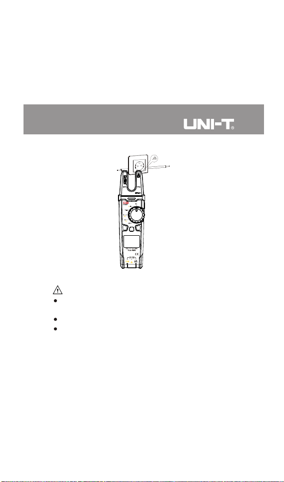
2) Bring the NCV sensor close to the charged AC wire under
test. As the intensity of the detected voltage increases, the
more the segments (“—”, “— —”, “— — —” or “— — — —”)
are displayed, the more frequently the buzzer beeps and
the indicator flashes. When the voltage is sensed in EFLo
mode, the indicator blinks in green, and when the voltage
is sensed in EFHI mode, the indicator blinks in yellow until
it turns red.
15 16
Page 17
Picture 7
Caution:
If the distance between the NCV sensor and AC wire is
different, the intensity sensed will vary.
Frequency of the detected voltage: 50Hz~60Hz
NCV sensing is not used as a basis for touch. Use the test
leads for contact measurement to determine whether the
voltage is safe before touch to prevent electric shock.
6. Others
1) Auto power off: During measurement, if there is no operation
of the function switch or any button for 15 minutes, the
meter will automatically shut down to save power. Users
can wake it up by pressing any button or restart it after
turning the function switch to the OFF position.
UT256A User Manual UT256A User Manual
Page 18

To disable the function, press and hold the auto power off
butto n in th e off stat e, and then t urn on the SEL ECT
buzzer will make five consecutive beeps. To meter. The
auto power off function, restart the meter.resume the
About 1 minute before auto power off, the buzzer will make
five consecutive beeps. If there is no operation within the 1
minute, the meter will automatically shut down accompanied
by one long beep.
2) Buzzer: When any button is pressed or the function switch
is turned, if it is valid, the buzzer will make one beep (two
short beeps indicating invalid but ton operation). In the
voltage or current measurement , the buzz er will beep
continuously to indicate the over range.
IX. Specifications
1. General Specifications
a. Max display: 6000 counts
b. Polarity display: Auto
c. Overload display: “OL” or “-OL”
d. Low battery indication: The “ ” symbol is displayed.
e. Test position error: If the measured source is not placed
in th e m easurem en t positi on of the open ja w fork in
measuring current, an error or erroneous reading will be
produced.
f. Drop protection: 2m
g. Jaw opening: 15mm
h. Battery: 2×1.5V AA batteries
17 18
Page 19

i. Auto power off: 15 minutes (can be disabled)
j . Dimensions: 220mm×58.5mm×38mm
k. Weight: About 260g (including batteries)
l. Operating altitude: ≤2000m
m. Operating temperature and humidity: 0°C~30°C (≤80%RH),
30°C~40°C (≤75%RH), 40°C~50°C (≤45%RH)
n. Storage temperature and humidity: -20°C~60°C (≤80%RH)
o. Electromagnetic compatibility: RF=1V/m, overall accuracy
= specified accuracy + 5% of range; RF>1V/m, not specified
2. Electrical specifications
a. Accuracy: ± (a% of reading + b digits), 1 year calibration
cycle
b. Ambient temperature and humidity: 23°C±5°C; ≤80%RH
Caution:
To ensure measurement accuracy, the operating temperature
should be within 18°C~28°C and the fluctuation range should
be within ±1°C. When the temperature is <18°C or >28°C,
add temperature coefficient error 0.1 x (specified accuracy)/°C.
UT256A User Manual UT256A User Manual
Page 20
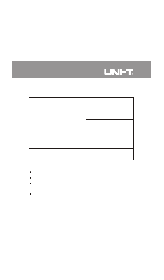
1) AC Current/Frequency
Range
200.0A
Frequency:
50Hz~60Hz
Caution:
AC current accuracy guarantee: 5%~100% of range
Current frequency response: 50Hz~60Hz
When the measured current is ≥ 200A, the indicator
red to remind users.turns
For frequency measurement, the input amplitude should
be >20A.
Resolution
0.1A
0.01Hz
Accuracy
0.2A ≤ACA ≤2.0A:
± (1.8%+2)
2.0A <ACA ≤5.0A:
± (1.8%+3)
5.0A <ACA ≤200.0A:
± (1.8%+5)
± (0.1%+5)
19 20
Page 21
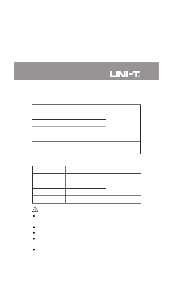
2) Voltage
AC voltage/frequency
Accuracy
Resolution
Range
0.001V
0.01V
0.1V
1V
0.01Hz~0.01kHz
± (1.2%+3)
± (0.1%+5)
6.000V
60.00V
600.0V
1000V
Frequency:
10Hz~10kHz
DC vol tage
Accuracy
Resolution
Range
6.000V
60.00V
600.0V
1000V
0.001V
0.01V
0.1V
1V
± (0.8%+3)
± (1.0%+5)
Caution:
For frequency measurement, the input amplitude should
be >8V RMS.
Input impedance: About 10MΩ
Maximum input voltage: 1000V
Voltage frequency response: 45Hz~400Hz, true RMS
display
Voltage accuracy guarantee: 5%~100% of range
UT256A User Manual UT256A User Manual
Page 22
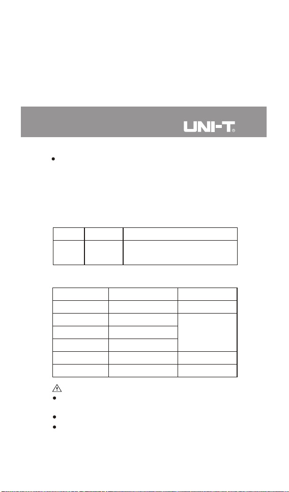
The AC crest factor of a non-sinusoidal wave decreases
linearly to about 1.8 at 6000 counts. The additional error
should be added for the corresponding crest factor as
follows:
a) Add 3% when crest factor is 1~2
b) Add 5% when crest factor is 2~2.5
3)Continuity
Range
Resolution
600.0Ω 0.1Ω
Resistance <10Ω: Buzzer beeps
Resistance >100Ω: no beep
Remark
4) Resistance
Range
600.0Ω
6.000kΩ
60.00kΩ
600.0kΩ
6.000MΩ
60.00MΩ
Caution:
Measurement result = displayed value – resistance of
shorted test leads
Open circuit voltage: About 1V
Overload protection: 1000Vrms
Resolution
0.1Ω
0.001kΩ
0.01kΩ
0.1kΩ
0.001MΩ
0.01MΩ
21 22
Accuracy
± (1.2%+2)
± (1.0%+2)
± (1.2%+2)
± (2.0%+5)
Page 23
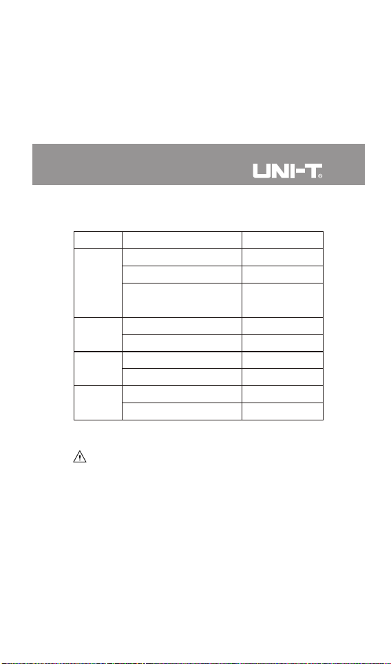
5) Audio/Visual alarm indicator
Status
< 12V (AC): Off
EFLo mode: Blinks in green
EFHI mode: Blinks in
yellow until it turns red
On, green
Off
<1000V: Off
≥1000V: On, red
<200A: Off
≥200A: On, red
Function
NCV
Continuity
AC/DC
voltage
Current
Description
No ACV signal
Weak ACV signal
Strong ACV signal
Continuity
Over range
Over range
X. Maintenance
Warning:
To avoid electric shock, make sure the test leads are
disconnected from the measured circuit before removing
the rear cover.
1. General Maintenance
1) Clean the meter casing with a soft cloth and mild detergent.
Do not use abrasives or solvents!
2) If there is any malfunction, stop using the meter and send
it for maintenance.
UT256A User Manual UT256A User Manual
Open circuit
Page 24
3) The maintenance and service must be implemented by
qualified professionals or designated departments.
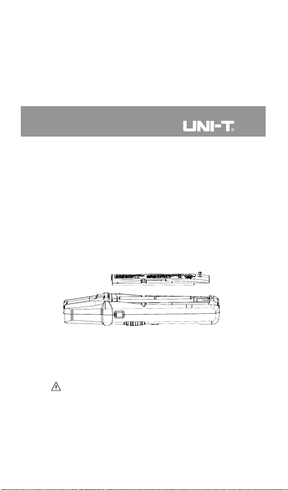
2. Battery Replacement (Picture 8)
1) Turn off the meter and remove the t est leads from the
input jacks.
2) Unscrew and remove the battery cover.
3) Replace with 2 standard AA batteries according to the
polarity indication.
4) Secure the battery cover and tighten the screw.
Picture 8
3. Test Lead Replacement
If the insulat ion on t he t est lead is damaged, replace it .
Warning:
Test lead assemblies to be used for MAINS measurement
should meet EN 61010-031 standard, the same rating or
better.
23 24
Page 25

UT256A User Manual UT256A User Manual
 Loading...