

Page 1
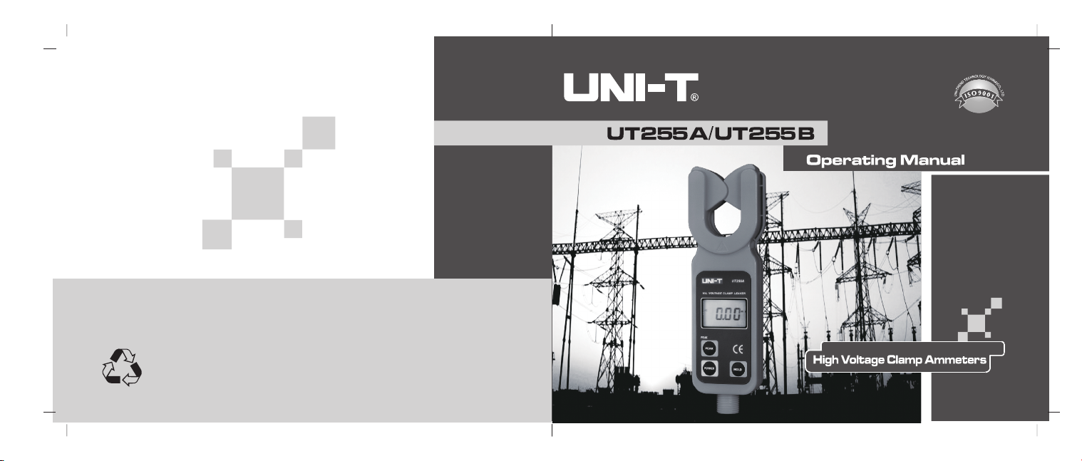
P/N:110401103626X
DATE:2018.06.26
REV.2
Page 2

Contents
TITLE PAGE
Warning 3
I. Introduction 6
II. Electrical Symbols 8
III. Model Comparison 9
IV.Technical Specifications 10
V. Meter Description 14
VI. Display Mode 16
1. LCD Display 16
2. Special Icon Description 17
3. Display Examples 18
VII. Operating Instructions 21
1. Measuring Instruction 21
(1) Power On/Off 21
(2) General Measurement 22
1
Page 3
TITLE PAGE
(3) PEAK Measurement 28
(4) Data Hold 29
(5) Data Save 29
(6) Data Access 30
(7) Data Delete 30
*(8) Data Transmission 30
2. Receiving Instructions 31
(1) Power On/Off 31
(2) Data Receive 32
(3) Data Hold 32
(4) Data Save 32
(5) Data Access 33
(6) Data Delete 33
VIII. Battery Replacement 34
IX. Packing List 36
2 3
Warnings
Thank you for purchasing UNIT series high voltage clamp ammeter.
In order to use the product properly, please follow instructions below:
-----Read this manual carefully and the operator is required to fully
understand the manual and operate skillfully before beginning
on-site tests.
-----Strictly observe safety rules and notes mentioned in this manual.
Page 4
4 5
Page 5

I. Introduction
High voltage clamp ammeter stands out from traditional concept and is
especially designed for on-line measurement on current, leakage current of
high-voltage lines and determining working status of zinc oxide arrester. It is
supported by latest CT and screening technologies and made up of exclusively
high-voltage tester and high-voltage insulation rods. UT255B, in particular can
offer wireless data transmission function and be equipped with wireless
receiver that allows it to straightly receive data within 20 meters. The meter is
also used as kinds of low-voltage leakage current clamp tester and
amperemeter that are capable of accuracy up to 0.01mA .You had better to
use wireless transmission model when focusing on measuring extremely
small flow of leakage current or current and at the same time offered with
timely data display.The design to integrate both clamp jaw and guide zone
ensures this kind of meter to enjoy high accuracy, reliability and stability all
the year around, and it is offered with insulation rods with outstanding
6 7
features such as moisture proof, high temperature resistance, anti-strike and
bending, high insulation, extendibility ,ect.
With the insulation rod, the meter can measure leakage current in highvoltage lines below 60kV and on-line current, and identify if zinc oxide
arrester is moisture-affected or not. There are also other functions provided
for the meter: peak value hold, data hold, data save and wireless data
transmission. Given the condition that high-voltage clamp can be easily
connected or disconnected to measured lines with the help of insulation rods,
so the meter can be widely used in transformer station, power plant, mining,
inspection center, electrician maintenance and repairing center for conducting
leakage current testing and outdoor electrical operation.
This kind of meter is also used as high/low-voltage current transformer
ratio tester and zinc oxide arrester meter, that is to say it can respectively
measure two times of loop current of current transformer and then calculate
Page 6
the ratio or reduced ratio. One thing to mention is: under general circumstances,
considering the leakage current should be lower than 500uA for a running
arrester, the meter can tell us the working status of the arrester. If checked
out with leakage current higher than 500uA, the arrester may have been
contaminated, moisture-affected or experienced aging, because the higher
flow of leakage current it is, the more severe phenomena above are.
Warning! Confirm to the safety instructions, otherwise it may cause
personal injury or damage to the meter.
Alternating Current AC
Direct Current DC
III. Model Comparison
under general circumstances
II. Electrical Symbols
Extreme danger! To avoid personal injury or accidents in case of
electric shock, observe safety rules strictly.
Danger! To avoid personal injury or accidents in case of electric
shock, please follow safety notes.
8 9
Model
UT255A 10uA 600A 10uA
UT255B 10uA 600A 10uA
Range
Resolution
Jaw Size
33mm
33mm
Notes
General Type
Special, with
wireless
transmission
function
Page 7
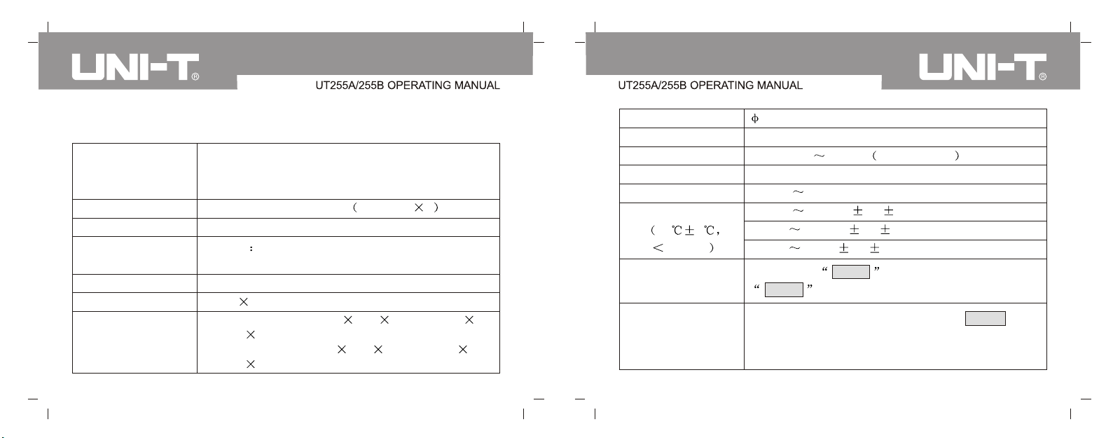
IV. Technical Specifications
To measure high-and low-voltage AC leakage current
Functions
Power
Measuring Mode
*Transmission mode
Display Mode
LCD Size
Dimensions
10 11
and on-line current; indirectly obtain ratio of current
transformer
DC6V Alkaline dry battery 1.5V AAA 4
Clamp-type CT, integral mode
UT255B 433MHz wireless transfer up to about 20
meters
4- digit LCD display, backlight, suitable on dark sites
47mm 28.5mm
High-voltage tester (wide high thick): 68mm
245mm 40mm
UT255B Receiver (wide high thick): 75mm
170mm 30mm
Jaw Opening
Sampling Rate
Measuring Range
Resolution
Function Switchover
Accuracy
23 5
80%RH
Data Save
PEAK Hold
33mm
2 times per second
AC 0.01mA 600.0A 50/60Hz auto
10uA
0.01mA 600A automatically switch
0.01mA 100.0A: 1% 5dgt
100.0A 200.0A: 2% 5dgt
200.0A 600A: 3% 5dgt
Max.99sets, MEM icon displays during storing,
FULL icon shows if fully save
Automatically hold peak values, Press PEAK button
under general measuring mode to start, indicated by
peak light, repress to switch off
Page 8
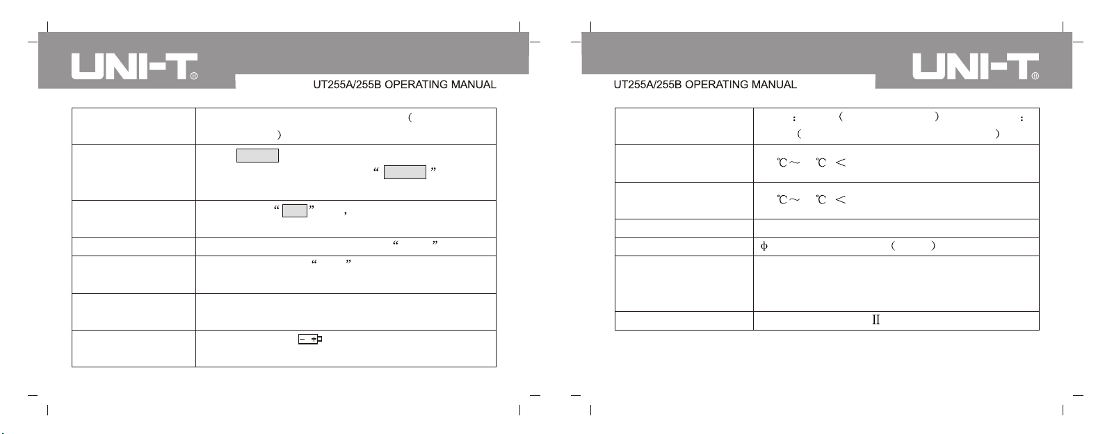
Line Voltage
Data Hold
Data Access
Overload Display
* Display for no signal
Auto Power Off
Battery Voltage
To measure line voltage below 60kV operate with
insulation rod
Press HOLD button to hold data under general
measuring mode, indicated by HOLD icon, then
repress to cancel the operation.
Indicated by MR icon able to scroll up or down
to read out data
Out of-range display: indicated by OL A icon
Dynamic display of no- - icon when receiving no
signal
15 minutes later after power on, to conserve power
energy
Low battery icon displays with voltage lower
than 4.8V, please timely change the battery
Weight
Operating
Temperature /Humidity
Storage
Temperature/ Humidity
*Interference
Insulation Rod
Insulation Strength
Structure
Tester 335g battery included ; total weight
2.5Kg insulation rod and battery included
-20 40 ; 80%Rh
-20 60 ; 70%Rh
No 315MHz, 433MHz shared frequency interference
32mm, 1m per piece 5PCS
Insulation strength between fifth insulation rod and
tester housing: AC 100kV/rms; between tester
housing and iron core: AC1000V/rms
Leakage resistance type
12 13
Page 9
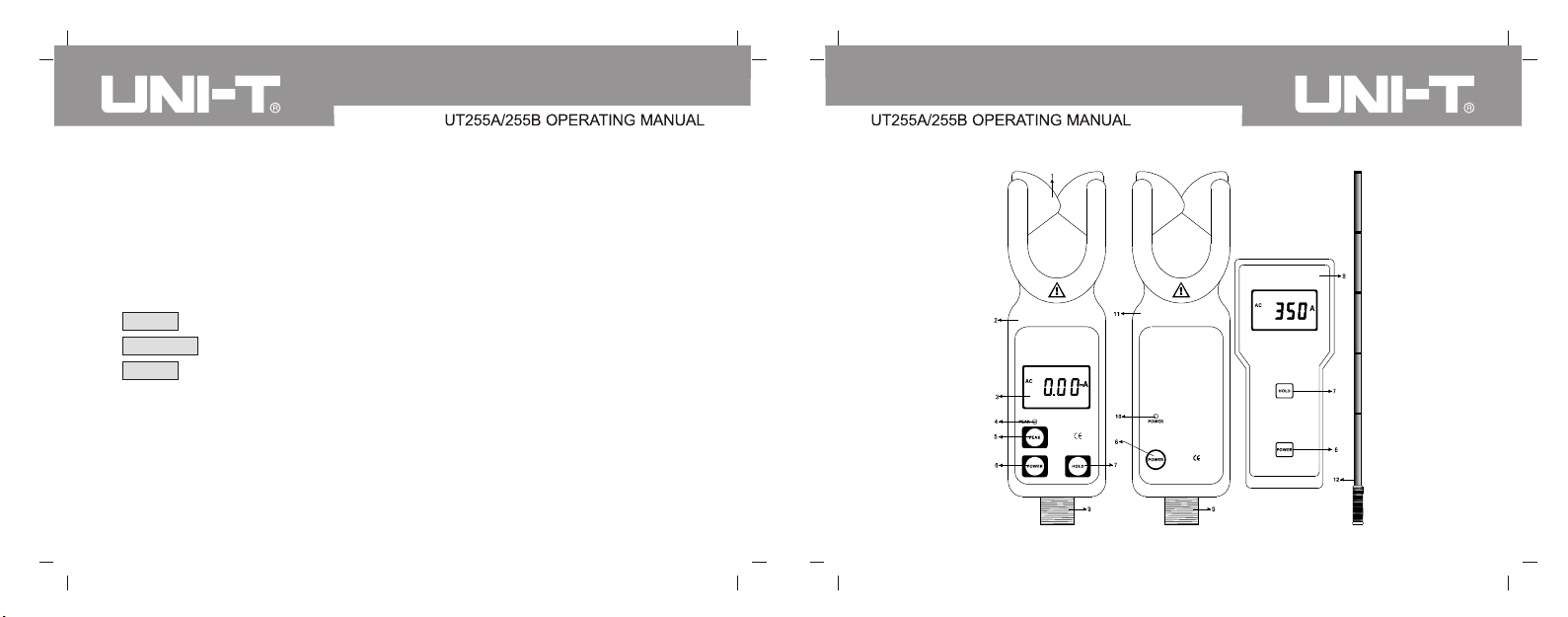
V. Meter Description
1. Clamp Jaw (Guide zone included)
2. UT255A Tester
3. LCD Display
4. PEAK Measuring Indication
5. PEAK Button
6. POWER Button
7. HOLD Button
* 8. UT255B Receiver
9. Insulation Rod connection Terminal
*10. POWER Indication
*11. UT255B tester
12. Insulation Rod (5 Pcs)
14 15
Page 10
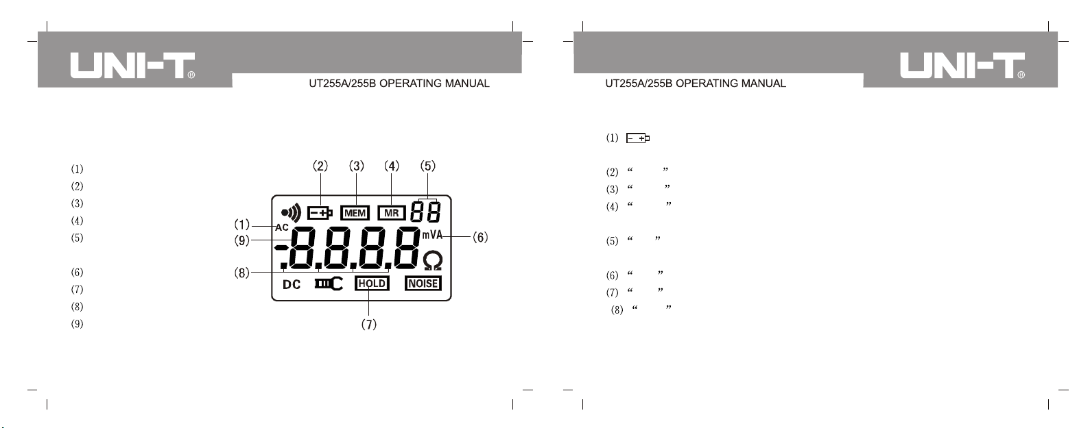
VI. Display Mode
1. LCD display
. AC icon
. Low battery icon
. Data Save Display
. Data Access Display
. 2-digit serial numbers
for data save
. Unit Icon
. Data hold Display
. Decimal Point
. 4-digit LCD Display
16 17
2. Special Icon Description
. Low battery displays with voltage lower than 4.8V, please change
batteries timely.
. OL A icon indicates measured current is out of limit.
. MEM icon displays during data save process.
. FULL icon flashes when maximum value of 99sets are achieved,
indicating no save operation any more.
. MR icon displays together with saved data serial numbers during data
research.
. End is to indicate exiting the process.
. dEL indicates during data delete process.
* . no- - dynamically indicates no signal is received; it is likely the tester
is not under testing mode, or being adjusted for right receiving place and
distance.
Page 11
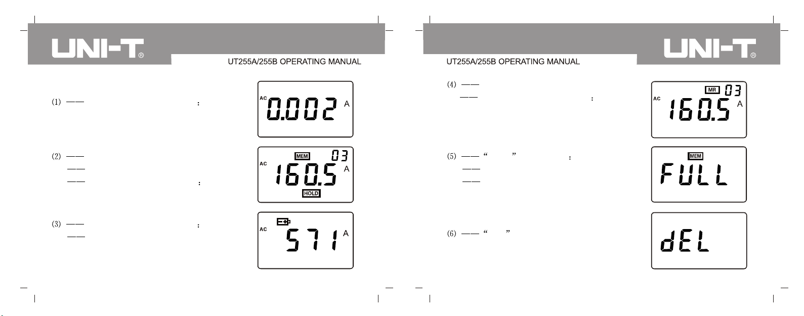
3. Display Examples
. Measured current displayed
0.002A (2mA)
. Access to data No.03
Measured current displayed 160.5A
. Displayed data hold
Saved data serial number 03
Measured current displayed 160.5A
. Measured current displayed 571A
Low battery display, please change
the battery.
18
. FULL icon flashes
Max.99 is achieved.
Memory needs clearing before resave.
. dEL to indicate data clearing.
19
Page 12
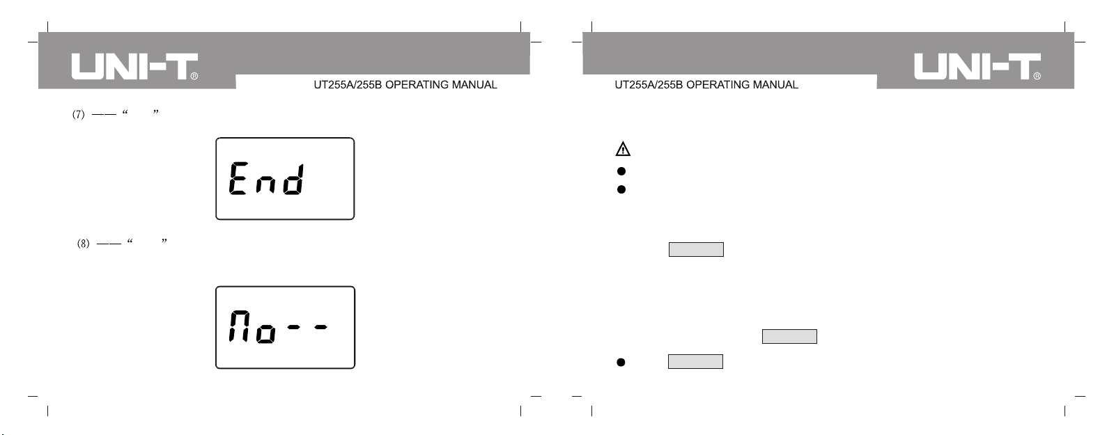
. End display to exit the operation
* . no- - dynamic display No signal received.
VII. Operating Instructions
Notes:
Please Check if there is any damaged parts or not before safe use.
Install the battery as required in the manual
1. Testing Instructions
(1) Power On/Off
Press POWER to power on, display LCD and enter into general
measuring mode. You should change the battery if dark LCD appears after
power on and may be caused by low battery voltage. To conserve power
energy, the meter will automatically switch off 15 minutes later after power
on, indicated by 30 seconds of LCD flashing. And you can continue
operations by pressing POWER button to stop LCD flashing.
20
Press POWER button to switch off under HOLD mode
21
Page 13
Press POWER button to switch off under general measuring mode.
Press POWER button to switch off under PEAK mode.
Under data access mode, long press HOLD button to exit and return to
general measuring mode, indicated by End icon during this process,
then press POWER button to power off.
(2) General Measurement
Dangerous Voltage!
High Voltage, extreme Danger! To avoid personal injury or accidents in
case of electric shock, only trained and authorized staff is allowed to
operate and should strictly observe safety rules.
Danger! To avoid personal injury or damage to the meter in case of electric
shock do not measure line voltage higher than 60KV.
Danger! Do not measure line current higher than 600A, otherwise it may
cause personal injury or damage to the meter in case of electric shock.
22 23
General Measurement: LCD will display real-time measured current during
measuring process. Displayed data on LCD varies with current flow and will
be back to zero if no measuring result has been held after disconnecting the
tester with measured lines.
General measuring mode is suitable for short-distance operation and
facilitates direct reading of LCD data. B Type model is not restricted to this
distance limit.
Warning !
Connect insulation rods and ensure right connection before measurement.
Try not to avoid earth strike to the meter when connecting it to rods.
Only exclusive insulation rods are allowed to connect to the meter.
Lean down and pull back insulation rods after finishing testing, then
disconnect the tester first and discharge rods later to avoid earth strike to
the tester
Page 14
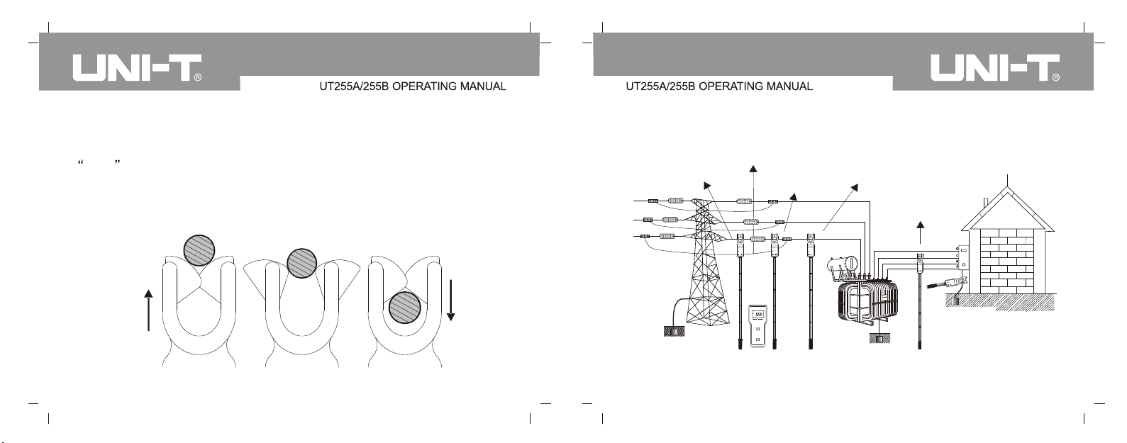
Locate conductor to be measured at the center of clamp guide zone after
normally power on, see Figure A. Guide zone should be kept perpendicular
to the conductor when moving the meter forward to completely enclose it. If
OL A displays on LCD, it indicates that measured current is out of limit
and requires higher range or choose another meter, then if disconnecting the
Ground Terminal
conductor with the meter, pull back the meter (see Figure C) and try to keep
the conductor perpendicular to the guide zone during this operation.
The Conductor
Pull Forward
Guide Zone
Measuring Leakage
Current of Zinc Oxide
Arrester
High-Voltage
Terminal
Measuring Current in
High-Voltage Circuit
Measuring Current in
Low-Voltage Circuits
Ground Leakage
Current Testing
Figure A
Figure B
Pull Back
Figure C
Grounding
Grounding
Grounding
24 25
Page 15
Hig
h-Volta
cui
Cir
ge
t
High-Voltage
Terminal
Hig
h-Voltag
Circu
e
it
High-Voltage
Terminal
Notes:
Given the fact that leakage current should be lower than 500uA for running
arrester(Just for reference, specific data are subject to standards of target
Arrester
Ground Line
Arrester
Ground Line
country /state), we can tell working status of arrester based on measured
leakage current. If leakage current is over 500uA and ruling out high-voltage
factor, the arrester may have been contaminated, moisture-affected and
aging to cause this problem. The more flow of leakage current it is, the
more severe the phenomenon is. The operator can decide to repair the
arrester or discharge it for lab testing based on leakage current flow so as
to avoid blind operations.
Press HOLD button to return to general measuring mode if under HOLD
mode.
Measuring Leakage
Current of Zinc Oxide
26 27
Arrester
Press HOLD button to return to general measuring mode if under data
access mode.
.
Page 16
Press PEAK button to return to general measuring mode if under PEAK
mode
The meter will automatically return to general measuring mode after data
delete
Notes:
Attention! For the sake of your safety, disconnect the meter with the
conductor and do not keep it connected for a long time.
(3) PEAK Measurement
Peak Measuring: to obtain maximum current value. The meter can
automatically compare changing currents, hold the existing maximum
value of current and still keep it after disconnecting the meter to the
conductor. Such operation is often used when direct reading on LCD data
is not available.
Press PEAK button to switch from general measuring mode to PEAK
28
Mode, indicated by PEAK light. Then the meter will display and
automatically hold the maximum current value.
If under other modes, you need to return to measuring mode before
starting PEAK measurement.
Press PEAK to exit and go back to general measurement mode,
indicated by End during the process.
(4) Data Hold
Press HOLD button to maintain data on LCD under general measuring
mode, indicated by HOLD icon, repress to cancel the operation and
switch into general measuring mode, then HOLD icon will disappear.
(5) Data Save
Under measuring mode, the meter will automatically number the current
data when pressing HOLD button to maintain data. MEM icon
flashes during this process. The maximum storage is 99 sets and
achieved when FULL icon continuously flashes to indicate you should
29
Page 17
Lear the memory for second save.
(6) Data Access
Under general measuring mode, press both PEAK + POWER buttons to
access data, indicated by MR icon and meanwhile data No.01 shows.
You can scroll up or down to read other data by using PEAK or POWER
button. If final set of data is obtained, the first set of data will then
automatically display.
Press HOLD to exit and return to general measuring mode, indicated by
End icon during this process
(7) Data Delete
If still under data access mode, press PEAK + POWER buttons to clear
the memory and return to general measuring mode, indicated by dEL
icon during this process.
*(8) Data Transmission
UT255B model: it can offer wireless data transmission function and allow
30 31
testing results to send back to the receiver in a wireless way. So the
receiver can provide real-time data and is easy to observe. Send back
signals only under measuring mode. If not successfully receiving those
signals, it will dynamically display no- - icon.
UT255B; it can wirelessly transfer data and the receiver can receive data
within about 20 meters even through walls.
2. Receiving Instructions
(1) Power On/Off
Press POWER button to switch on, display LCD and enter into data
receiving mode. You should change the battery if dark LCD appears and
may be caused by low battery voltage. To conserve power energy, the
receiver will automatically switch off 15 minutes later after power on,
indicated by 30 seconds of LCD flashing. You can press POWER button
to stop the flashing for further operation.
Page 18
Under HOLD mode, press POWER button to switch off.
If under data access mode, first long press POWER button (over 3
seconds) to exit and return to receiving mode, then repress to power off,
indicated by End icon during this process.
(2) Data Receive
The receiver will immediately go into receiving mode after power on and
display on-line results if data signal have been sent back. If not, the
receiver will continue to search for signals and dynamically display no- icon.
(3) Data Hold
Under data receiving mode, short press HOLD button to keep the LCD
display, indicated by HOLD icon. Press again to cancel the operation
and return to receiving mode, then HOLD icon will disappear.
(4) Data Save
Under receiving mode, the receiver will automatically number current data
32 33
when pressing HOLD button to keep data. MEM icon displays one
time during the process. The maximum storage is 99 sets and achieved
when FULL icon continuously flashes to indicate the memory needs
clearing for second save.
(5) Data Access
Under receiving mode, press HOLD + POWER buttons to enter into data
access mode. MR icon and at the same time data NO.01 display on
LCD, then you can scroll up or down to access more data by using HOLD
or POWER button. If final set of data is obtained, the meter will
automatically return to the first set.
Long press POWER button (over 3 seconds) to exit and return to data
receiving mode, indicated by End icon during this operation.
(6) Data Delete
Under data access mode, press HOLD + POWER to clear the memory
and return to data receiving mode, indicated by dEL icon during this
process.
Page 19
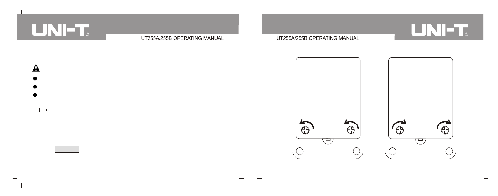
VIII. Battery Replacement
Warning !
To avoid risks do not test if battery cover is not well placed.
To avoid damage to the meter, please ensure right polarity of battery.
Do not combine old batteries with new ones for use.
1. Low battery icon displays with voltage lower than 4.8V, please
change batteries timely.
2. Power off, confirm it and then loosen two screws on the battery cover. With
the cover opened, change old batteries with new specified ones. Ensure
right polarity is selected and tighten screws to close the cover
3. Press POWER button and check if the meter can successfully power on,
if not, repeat the second step.
34 35
Battery Cover
Loose
Battery Cover
Tight
Page 20
 Loading...