

Page 1
P/N:110401108651X
UT203R/UT204R
AC/DC Clamp Meters
User Manual
Preface
Thank you for purchasing the new clamp meter. In order to use this
product safely and correctly, please read this manual thoroughly,
especially the Safety Instruction part.
After reading this manual, it is recommended to keep the manual at
an easily accessible place, preferably close to the device, for future
reference.
Limited warranty and liability
Uni-Trend guarantees that the product is free from any defect in material
and workmanship within one year from the purchase date. This warranty
does not apply to damages caused by accident, negligence, misuse,
modification, contamination and improper handling. The dealer shall
not be entitled to give any othe r warranty on be half of Uni-Trend. If
you need warranty service within the warranty period, please contact
your seller directly.
Uni-Trend will not be responsible for any special, indirect, incidental
or subsequent damage or loss caused by using this device. As some
countries or regions do not allow limitations on implied warranties and
incidental or subsequent damages, the above limitation of liability may
not apply to you.
1. Overview
The UT203 R/UT204R are porta ble true R MS AC/DC clamp meters
with aut omatic range. Th ey are de signed accordi ng to EN 61010-1
CAT II 600V/CAT III 300V safety standards, and come with full-function
prote ction which ensur es use rs a sa fe and relia ble me asure ment
experience. Aside from basic measurement functions, they also have
high precision current scale and high voltage frequency measurement
extension.
2. Features
True RMS measurement
Audio visual NCV electric field detection
High voltage frequency range: 10Hz~60kHz; low voltage frequency
range: 60Hz~10MHz
UT203R AC/D C current range: 40 A, 400A, frequenc y respons e:
45Hz~400Hz
UT204R AC/D C curren t range: 6 0A, 600A , freque ncy respo nse:
45Hz~400Hz, live/neutral wire detection
ACA/DCA mode memory function for current measurement
Large capacitance (UT203R: 40mF, UT204R: 60mF) and temperature
Tmeasurement (U 204R)
Large LCD and fast refresh rate (3 times/s), capacitance measurement
response time:
≤1mF: less than 3s; ≤10mF: about 6s; ≤60mF: about 8s
Full- funct ion fa lse det ectin g prot ection for up to 600 V (3.6k VA)
energy surge; overvoltage and overcurrent alarm
The powe r consu mption w ithout backlig ht is ab out 1.8 m A. The
circuit has an automatic power saving function. The consumption
in sleep state is <11uA, which effectively extends the battery life to
400 hours.
Pleas e read the safety and wa rnin g part s in th is ma nual
thoro ughly.
Caution: Please read the safety instructions carefully before use.
3. Standard Accessories
Open the package and check the below items, if any is missing or
damaged, please contact your supplier immediately:
User manual ----------------------- 1 pc
Test leads --------------------------- 1 pair
K-type temperature probe ------ 1 pc (Only UT204R)
Cloth bag ---------------------------- 1 pc
4. Safety Instructions
WARNING
To ensure safe operation and service of the tester, follow these
instructions. Failure to observe these warnings can result in severe
injury or death.
The meter is designed ac cording to E N61010-1, 6 1010-2-032 /033
and electromagnetic radiation protection EN61326-1 safety standards,
and conf orms to d ouble i nsulati on, CAT II 600 V, CAT III 300V and
pollution grade II. In case the meter is not used properly as instructions,
the protection provided may be weakened or lost.
Before each use verify tester operation by measuring a known voltage.
Before use, please check if there is any item which is damaged or
behaving abnormally. If any abnormal item (such as bare test lead,
damaged meter casing, broken LCD, etc.) is found, or if the meter
is considered to be malfunctioning, please do not use the meter.
Do not use the meter if t he rear cove r or the batt ery cover is not
covered up, or it will pose a shock hazard!
Keep fi ngers be hind the f inger gu ards and a way from the metal
probe contacts when making measurements.
The function switch should be placed in the correct position before
measurement. It is forbidden to change the position during
measurement to avoid damage to the meter!
Do not apply voltage over 600V between any meter terminal and
earth ground to prevent electric shock or damage to the meter.
Use caution when working with voltages above AC 30Vr.m.s,
42Vpeak or DC 60V. Such voltages pose a shock hazard.
Never input voltage or current which exceeds the specified limit.
Maximum range should be selected if measured value is unknown.
Before measuring resistance, diode and continuity, please disconnect
all power and fully discharge all capacitors to avoid inaccuracy.
When the “ ” s ymbol appear s on th e LCD, p lease replac e the
batteries i n time to en sure measur ement accur acy. Batteries sh ould
be removed If the meter is long-term idle.
Do not change the internal circuit of the meter to avoid damage to the
meter and user!
Do no t expo se the m eter i n high temper ature /humi dity, flam mable ,
explosive or intense magnetic environments.
Clean the meter casing with a soft cloth and mild detergent. Do not use
abrasives or solvents!
5. Symbols
Description
Symbol
Caution, possibility of electric shock
Alternating current
Direct current
Equipment protected throughout by DOUBLE
INSULATION or REINFORCED INSULATION
Earth (ground) TERMINAL
Warning or Caution
Conforms to UL STD 61010-1, 61010-2-032, 61010-2-033,
Certified to CSA STD C22.2 No. 61010-1, 61010-2-032,
61010-2-033.
It is applicable to test and measuring circuits connected
directly to utilization points (socket outlets and similar
CAT II
points) of the low-voltage MAINS installation.
It is applicable to test and measuring circuits connected
CAT II I
to the distribution part of the building's low-voltage
MAINS installation.
6. General Specifications
Max LCD display counts: 4099 (U 203R), 6099 (U 204R)T T
Polarity display: Auto
Overload display: “OL” or “- OL”
Low battery indication: “ ” means low battery
Low battery shutdown prompt: The “Lo.bt” interface appears on LCD
and lasts for about 10s, the buzzer beeps 3 times, and the meter
automatically shuts down.
Test position error: If the source under test is not placed at the center
of the clamp jaws when measuring current, ±1.0% additional error in
reading may be produced.
Drop protection: 1m
The maximum size of jaw opening: 28mm in diameter
Battery: AAA 1.5V battery × 2
Auto power off (adjustable): The meter will auto power off if there is no
operation for 15 min.
Dimensions: 215mm × 63.5mm × 36mm
Weight: About 235g (including batteries)
Altitude: 2000m
Operating temperature and humidity: 0°C~30°C (≤80%RH), 30°C~40°C
(≤75%RH), 40°C~50°C (≤45%RH)
Storage temperature and humidity: -20°C~+60°C (≤80%RH)
Electro magneti c compati bility: RF=1V/m, overall accuracy =specifi ed
accuracy+5% of range; RF>1V/m, no specified calculation
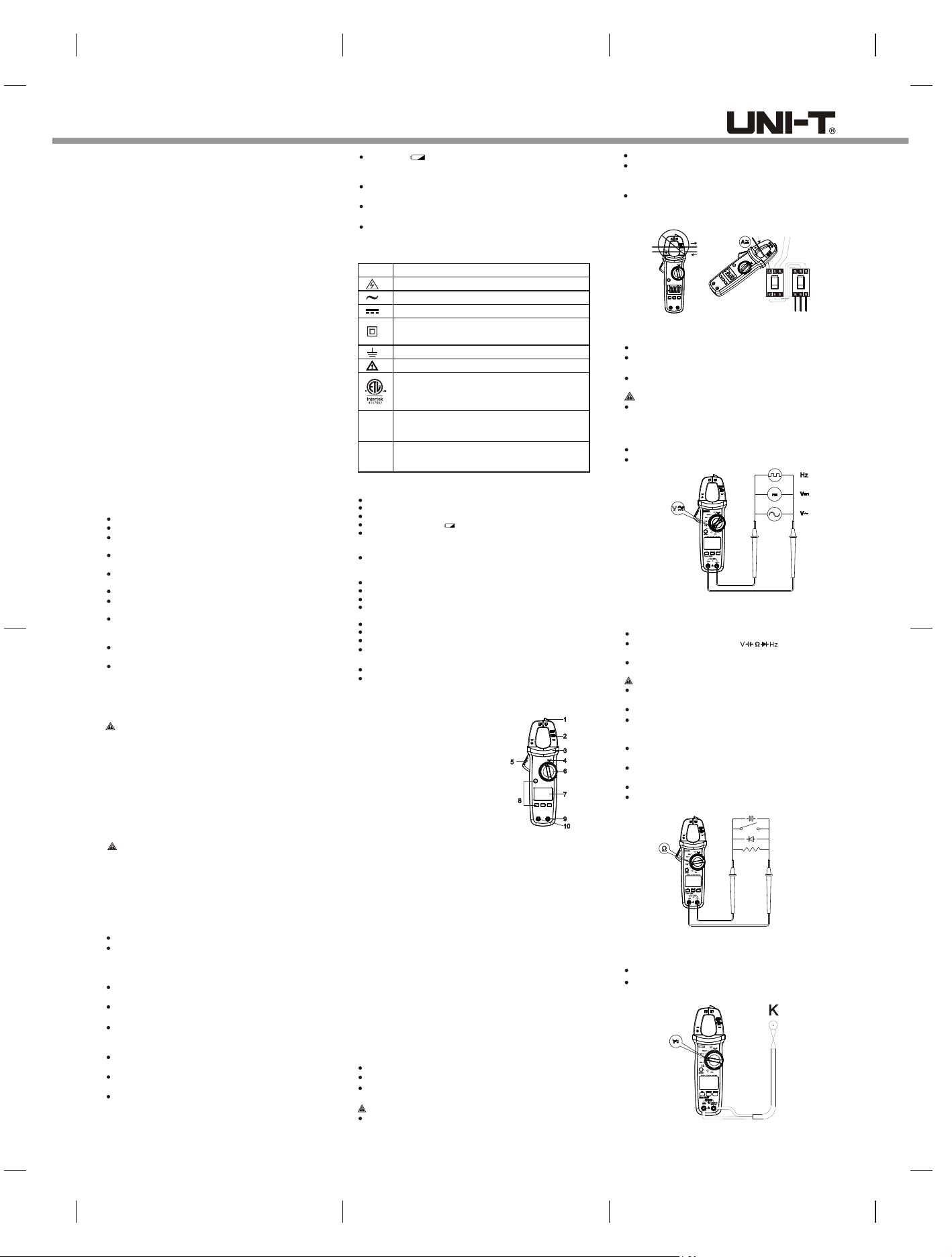
7. External Structure (Picture 1)
1) NCV sensing end
2) Clamp jaws
3) Hand guard
4) LED indicator
5) Jaw opening trigger
6) Function scale knob
7) LCD display
8) Function buttons
9) Signal input jack (red and positive +)
10)COM input jack (black and negative -)
Picture 1
8. Button Description
SELECT Button
In composite scale, press this button to switch between the corresponding
functions or ranges;
HOLD/BACKLIGHT Button
Short press this butto n to enter/e xit the data hold mode, and long pre ss
(about 2s) this button to turn on/off the backlight.
MAX/MIN Button
(valid for ACV/DCV, ACA/DCA, “C/”F, resistance and capacitance scales)
Short press this button to enter the maximum/minimum measurement mode
and long press this button to exit.
REL Button
(valid for ACV/DCV, DCA, “C/”F and capacitance scales).
Press this button to store the current reading as a reference for future
readings. When the LCD display value is reset to zero, the stored reading
will be subtracted from the future readings. Press this button again to exit
the relative value mode.
9.Operating Instructions
9.1 AC/DC Current Measurement (Picture 2)
Select the corresponding current range.
Press the trigger to open the clamp jaws, and fully enclose one conductor.
Only one conduct or can be m easured at a time , or the me asureme nt
reading will be wrong.
Caution:
Do not insert the tes ting l eads du ring cu rrent measur ement t o avoid
electric shock.
The current measurement must be taken with safeguard protection.
Pr ess th e RE L but ton to ret urn to z ero be for e th e D C cu rre nt
meas ureme nt, an d mean while the ce nter h ole of jaw sh ould b e
perpendicular to the current direction to ensure accuracy.
The open circuit zeroing reading may be relatively large after (high)
DC current measurement. Please perform the AC current detection
again to counteract the remanence signal by alternating electric field.
Current Measurement
Picture 2
9.2 AC/DC Voltage and Voltage Frequency (% duty cycle)
Measurement (Picture 3)
Select the corresponding function scale.
Insert the red te st lead into the “ positive” jack , and the black i nto
the “COM” jack.
Connect test leads with both ends of the measured objects.
Caution:
Do not input voltage above 600V to prevent electric shock or damage.
The input impedance of each range scale is 10MΩ, this load effect
in h igh resi sta nce m eas urem ent may c ause err or. If the i npu t
impedance is lower than 10kΩ, the error can be ignored (≤0.1%).
Be cautious to avoid electric shock when measuring high voltage.
Please check the functions by applying a known voltage before use.
Red Black
Picture 3
9.3 Continuity Test/Resistance/Diode/Capacitance
Measurement (Picture 4)
Select the corresponding function scale.
Insert the red test lead into the “ ” jack, and the black
into the “COM” jack.
Connect test leads with both ends of the measured object.
Caution:
Do not input voltage above DC 60V or AC 30V to avoid personal
injury.
Please disconnect all the other parts of the circuit to avoid inaccuracy.
Before the resistance online measurement, please do disconnect
all the power a nd fully discha rge all capacit ors to avoid inj ury or
device damage.
If the resistance is over 0.5Ω when the test leads are short-circuited,
please check the test leads for looseness or other abnormalities.
If the measu red res istor i s open or the r esist ance ex ceeds the
maximum range, the LCD will display “OL”.
Mea sure d val ue = d ispla yed v alue – pro be sh ort c ircu it va lue
It is recommended to use “REL” measurement mode for capacitance
less than 100nF.
Red Black
Picture 4
(UT204R only)
Capacitance
Continuity
Diode
Resistance
9.4 Temperature Measurement (UT202R only, Picture 5)
Select the temperature measurement function scale.
Insert K-type thermocouple to the meter, fix the temperature probe
on the measured object, and read after the value is stable.
Red
Black
Picture 5
Page 2
9.5 NCV AC Electric Fie ld Sens ing (Pictu re 6a)
The electric field sensing sensitivity is divided into two levels
(“EFHI” and “EFLo”). The meter defaults to “EFHI”. Users can select
different sensitivity levels according to the intensity of the measured
electric field. Select "EFHI" of NCV when electric field is around 220V
AC 50Hz/60Hz. Bring the NCV sensing end close to a charged electric
field (socket, insulated wire, etc.). The LCD will display the segment
"-" with beeps and red LED flashing. As the intensity of the measured
electric field increases, the more segments (----) display , the higher
frequency of buzzer beeps and LED flashes. Select “EFLo” when the
electric field is around 110V AC 50Hz/60Hz.
Caution:
Use the NC V se nsi ng e nd to ap proac h me asu red elect ric fie ld,
otherw ise th e measu remen t sensi tivit y will be affec ted. W hen the
measured electric field voltage is over 100V AC, observe whether the
conductor is insulated to avoid personal injury.
Picture 6a
9.6 Others
Auto power off: The meter will automatically power off to save power
if there is no operation for 15 min. You can wake it up by pressing
any button or restart it after turning the switch to OFF.
Press and hold the SELECT button in off state and then turn on the
meter again to disable the auto power off function. Restart the meter
after shut it down to resume this function.
Buzzer: When any button is pressed or the function switch is turned,
if it is valid, the buzzer will make one beep (about 0.25s). The buzzer
will also be ep intermit tently to ind icate the ov er range duri ng the
voltage or current measurement.
Low bat tery de tection : The bat tery vol tage wi ll be aut omatic ally
detected as long as the meter is on. If it is lower than 2.6V, the LCD
will display the “ ” symbol.
Low battery shutdown function: When the battery voltage is lower
than 2.5V, the LCD displays the “ ” symbol, the “Lo.bt” interface
appears and lasts for about 10s, the bu zzer make s consecu tive
beeps 3 times, and then the met er automatica lly shuts down ( no
is displayed).interface
10.Probe usage
TESTING IN CAT III MEASUREMENT LOCATIONS
Ensure the test lead shield pressed firmly in place. Failure to use
the CAT III shield increases arc-flash risk.
TESTING IN CAT II MEASUREMENT LOCATIONS
CAT III shields may be removed for CAT II locations. This will allow
testing on recessed conductors such as standard wall outlets.
Take care not to lose the shields.
11. Technical Specifications
Accuracy: ± (%reading + counts), the calibration period is 1 year.
Ambient temperature and humidity: 23°C±5°C; ≤80%RH.
Temperature coefficient: the accuracy assured temperature condition
is 18°C-28°C, the range of ambient temperature fluctuation is stable
within ±1°C. When the temperature is less than 18°C or over 28°C,
the additional temperature coefficient error is 0.1 x (specified
accuracy)/°C.
10.1 Current Measurement
AC Current
40.00A
400.0A
DC Current
40.00A
400.0A
Range
Range
UT204RUT203R
60.00A
600.0A
UT204RUT203R
60.00A
600.0A
Resolution
0.01 A
0.1 A
Resolution
0.01 A
0.1 A
Accuracy
±(2%+5)
Accuracy
±(2%+5)
Caution:
Accuracy guarantee range: 5%~100% of range
When the measured current reaches the warning value, there
will be an alarm sound (UT203R: 410A, UT204R: 610A)
With DC cur rent D CA mode, LCD ma y disp lay no n-zer o valu e
in open circuit state, users can press "REL" button to clear display
to zero before each measurement.
10.2 Voltage Measurement
DC Voltage
AC Voltage/Voltage Frequency
Caution:
UT203R: short press "SELECT” in AC voltage/Hz scale to enter the Hz
function;
UT204R: long press "SELECT" to enter/exit the Hz function , the input
range over 5V.
The input impedance is about 10MΩ
Current/voltage frequency response: 45Hz ~ 400Hz, displays true RMS
value
Accuracy guarantee range: 1%~100%
AC crest fa ctor of non- sinusoidal wave can rea ch 3.0 at 400 0 counts
while can only reach 1.8 at 6000 counts, the additional error should be
added for the corresponding crest factor as follows:
A. Add 3% when the peak factor is 1 ~ 2
B. Add 5% when the peak factor is 2 ~ 2.5
C. Add 7% when the peak factor is 2.5 ~ 3
Range
400.0mV
4.000V
40.00V
400.0V
600V
Range
4.000V
40.00V
400.0V
600V
Voltage Frequency
10Hz 60KHz~
UT204RUT203R
6.000V
60.00V
600.0V
UT204RUT203R
600.0mV
6.000V
60.00V
600.0V
Resolution
0.1mV
0.001V
0.01V
0.1V
1V
Resolution
0.001V
0.01V
0.1V
1V
0.01Hz~0.01kHz
Accuracy
±( . +0 7% 3)
±( . +0 5% 2)
Accuracy
±( . +1 0% 5)
±( . +0 8% 5)
±( . %+ )0 5 2
10.3 Continuity/Diode Measurement
Function
Range
400.0Ω/600.0Ω
4.000V/6.000V
Resolution
0 1. Ω
0 001V.
Accuracy
≤10Ω: Consecutive beeps
≥31Ω: No beep
The median: uncertain
The open circuit voltage is
about 4V
For the silicon PN junction
diode, the voltage value is
generally about 0.5~0.8V.
10.4 Resistance Measurement
Range
400.0Ω
4.000kΩ
40.00kΩ
400.0kΩ
4.000MΩ
40.00MΩ
Caution:
Measured resistance value = displayed value – resistance value
of short circuited test leads
Open circuit voltage is about 1V
Overload protection: 600Vrms
UT204RUT203R
600.0Ω
6.000kΩ
60.00kΩ
600.0kΩ
6.000MΩ
60.00MΩ
Resolution
0 1. Ω
0 001K. Ω
0 01K. Ω
0 1K. Ω
0 001M. Ω
0 01M. Ω
Accuracy
±( . +1 0% 2)
±( . +0 8% 2)
±( . %+ )2 5 5
10.5 Capacitance Measurement
Range
40.00nF
400.0nF
4.000uF
40.00uF
400.0uF
4.000mF
40.00mF
Caution:
Measured value = displayed value - open circuit value of the test leads
(For capacitance ≤100nF, “REL” mode is recommended, open circuit
has residual reading). The guaranteed accuracy is 1%~100%.
Overload protection: 600Vrms
UT204RUT203R
60.00nF
600.0nF
6.000uF
60.00uF
600.0uF
6.000mF
60.00mF
Resolution
0.01nF
0.1nF
0.001μF
0.01μF
0.1μF
0.001mF
0.01mF
Accuracy
±( %+ )4 5
± %10
10.6 Frequency Measurement
Range
10Hz~10MHz 0.01Hz~0.01MHz
Caution:
Measurement sensitivity:
≤100kHz: 200mVrms≤ input range≤30Vrms;
>100kHz~1MHz: 600mVrms≤ input range≤30Vrms;
>1MHz~10MHz: 1Vrms≤ input range≤30Vrms.
Resolution
Accuracy
±(0.1%+4)
Duty ratio is only applicable to ≤10kHz square wave measurement
with a range of 1Vp-p:
If frequency≤1kHz, duty cycle will be 10.0%-95.0%;
If frequency>1kHz, duty cycle will be 30.0%-70.0%.
10.8 Temperature Measurement (UT204R only)
Range
-40℃~40℃
40℃~500℃
500℃~1000℃
-40℉~104℉
104℉~932℉
932℉~1832℉
Caution:
The meter displays "OL" after startup, it is only suitable for K-type
thermocouple (Nickel-Chromium ~ Nickel-Silicon temperature
sensor) and temperature measurements below 1000°C/1832°F.
The formula for Celsius to Fahrenheit is °F =1.8°C + 32.
Resolution
1℃
1℉
Accuracy
±4℃
±(1.5%+5)
±(2.0%+5)
±6℉
±(2.0%+6)
±(2.5%+4)
10.9 NCV
Electric field
Range
NCV
sensing
sensitivity level
EFLo
EFHI
The electric field sensing sensitivity
is divided into two levels (“EFHI” &
“EFLo”). The meter defaults to “EFHI”.
a) AC voltage above 24V±6V can be
sensed. "EFLo" mode is recommended
when the power frequency voltage is
110V.
b) "EFHI" can be set in 220V condition.
AC voltage above 74V±12V can be
sensed with getting close to wires,
and identify whether the main socket
is charged or to judge the live/neutral
wire of socket according to the intensity
of sensing.
Note: Test results may be affected by
different socket designs or wire I
nsulation thickness.
Accuracy
11. Maintenance
Warning: Before opening the rear cover of meter , remove test
leads to avoid electric shock.
11.1 General Maintenance
Clean the me ter casing w ith a soft clo th and mild d etergent. Do
not use abrasives or solvents!
Do not use the tester or test leads if they appear to have any
abnormality.
The maintenance and service must be implemented by qualified
professionals or designated departments.
11.2 Battery Replacement (Picture 7)
When t he “ ” s ymbo l appe ars on the L CD, pl ease r epla ce the
batteries in time to ensure measurement accuracy. Batteries
specification:
2 standard AAA 1.5V batteries.
Operation
Turn off the meter and remove the test leads from the input terminals.
Unscrew the screw of the battery compartment, remove the battery
cover, and take out the used batteries as shown.
Repla ce the 2 s tandar d AAA batteri es acco rding t o the po larity
indication.
Picture 7
 Loading...