

Page 1
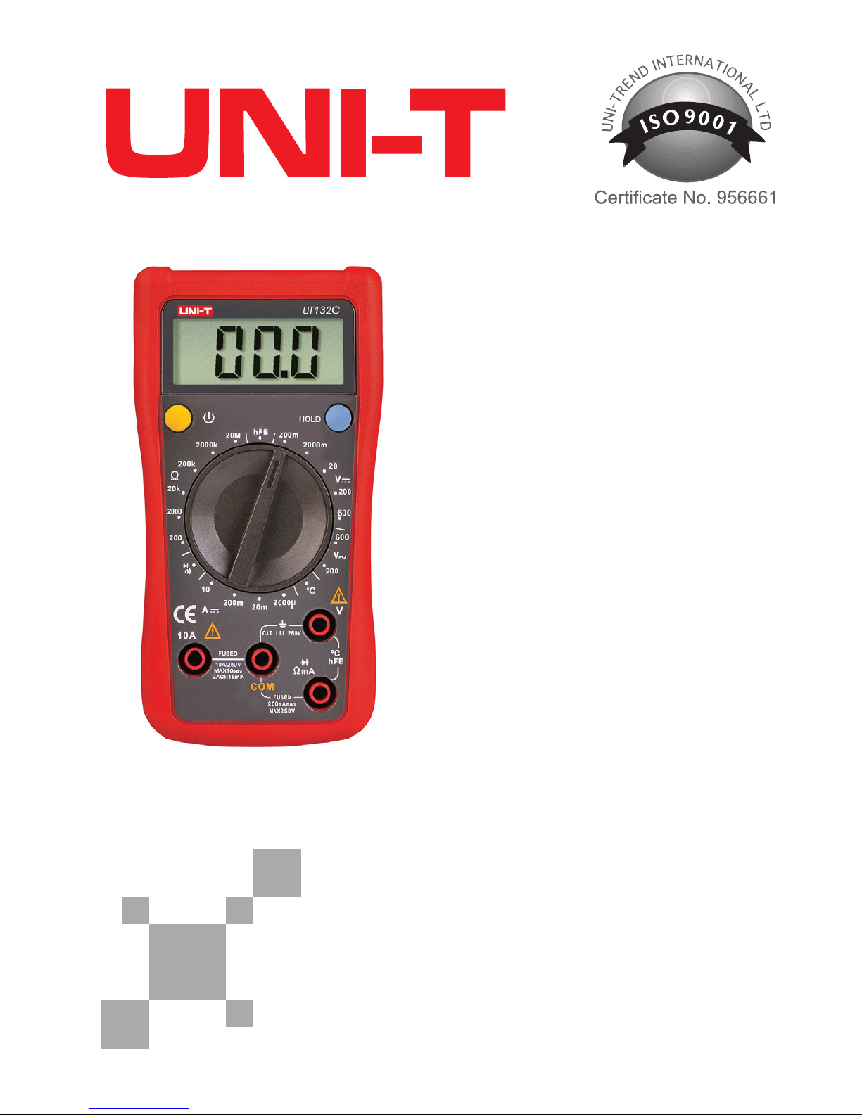
Instrukcja obsługi
PL
Owner’s manual
EN
Palm size
digital
multimeter
MIE0141
MIE0142
Page 2

Page 3

3
Owner’s manual
EN
OVERVIEW
Warning
To avoid possible electric shock or personal injury, and to avoid
possible damage to the Meter or to the equipment under test,
adhere to the following rules:
● Before using the Meter inspect the case. Do not use the Meter if
it is damaged or the case (or part of the case) is removed. Look for
cracks or missing plastic. Pay attention to the insulation around the
connectors.
● Inspect the test leads for damaged insulation or exposed metal.
Check the test leads for continuity. Replace damaged test leads
with identical model number or electrical specications before using the Meter.
MIE0141/MIE0142 multimeter is a hand-held 3 1/2 digital display
digital multimeters with advanced design, multiple entire functions,
novel gurations and reliable performance. This meter is fully capable to measure voltage both AC and DC, DC current, resistance,
inductance, temperature and forward voltage drop of diode, tran-
sistor, hFE and continuity test etc. Please use multi-purpose socket
to measure SMT as well. This operating manual covers information
on safety and cautions to fulll CE mark standard. Please read the
relevant information carefully and observe all the warnings and
notes strictly.
Warning: To avoid electric shock or personal injury, read the
“Safety information” and „Rules for Safe Operation” carefully before
using the meter.
RULES FOR SAFE OPERATION
Page 4

Owner’s manual
4
EN
● Do not apply more than the rated voltage, as marked on the
Meter.
● When measurement has been completed, disconnect the con-
nection between the test leads and the circuit under test and turn
the Meter power off.
● The rotary switch should be placed in the right position and no
any changeover of range shall be made during measurement is
conducted to prevent damage of the Meter.
● Do not carry out the measurement when the Meter’s back case
and battery compartment are not closed to avoid electric shock.
● When the Meter working at an effective voltage over 60V in DC
or 30V rms in AC, special care should be taken for there is danger
of electric shock.
● Use the proper terminals, function, and range for your measurements.
● Do not use or store the Meter in an environment of high temperature, humidity, explosive, inammable and strong magnetic eld.
The performance of the Meter may deteriorate after dampened.
● When using the test leads, keep your ngers behind the nger
guards.
● Disconnect circuit power and discharge all high-voltage capacitors before testing resistance, continuity and diode.
● Replace the battery as soon as the battery indicator appears.
With a low battery, the Meter might produce false readings that can
lead to electric shock and personal injury.
● When servicing the Meter, use only the same model number or
identical electrical specications replacement parts.
Page 5

5
Owner’s manual
EN
● The internal circuit of the Meter shall not be altered at will to
avoid damage of the Meter and any accident.
● Soft cloth and mild detergent should be used to clean the surface
of the Meter when servicing. No abrasive and solvent should be
used to prevent the surface of the Meter from corrosion, damage
and accident.
● The Meter is suitable for indoor use.
● Turn the Meter off when it is not in use and take out the battery
when not using for a long time.
● Constantly check the battery as it may leak when it has been using for some time, replace the battery as soon as leaking appears.
A leaking battery will damage the Meter.
Page 6
Owner’s manual
6
EN
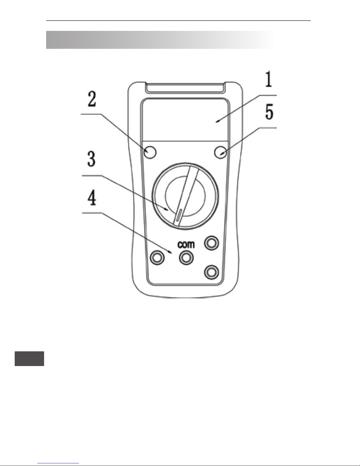
THE METER STRUCTURE
1. LCD display
2. Power button
3. Rotary switch
4. Input terminals
5. Hold button
Diagram 1
Page 7
7
Owner’s manual
EN
MEASUREMENT OPERATION
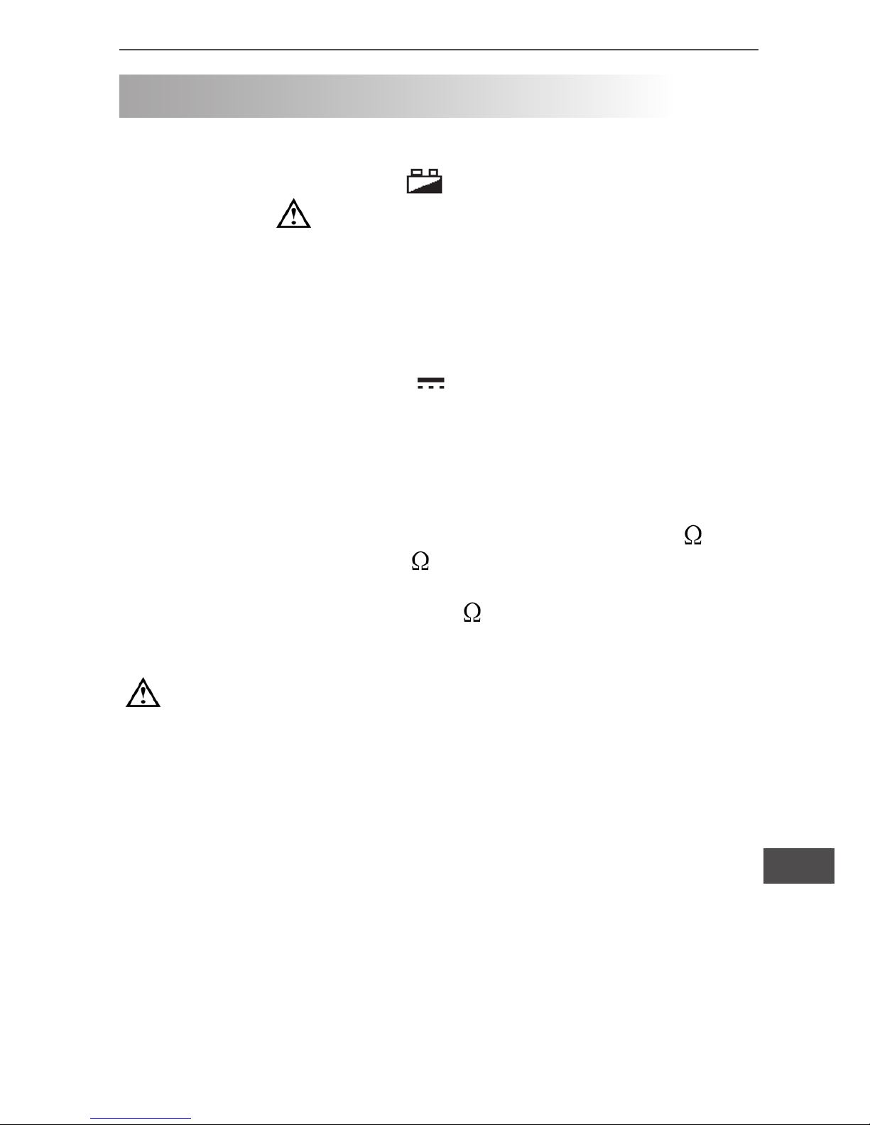
First check on 9V battery, then turn rotary switch to the measuring position. lf the low battery,
sign will be displayed on LCD
panel. Nearly to
sign on the meter front panel terminal input
which alarm not exceed the testing voltage and current input value
limitation.
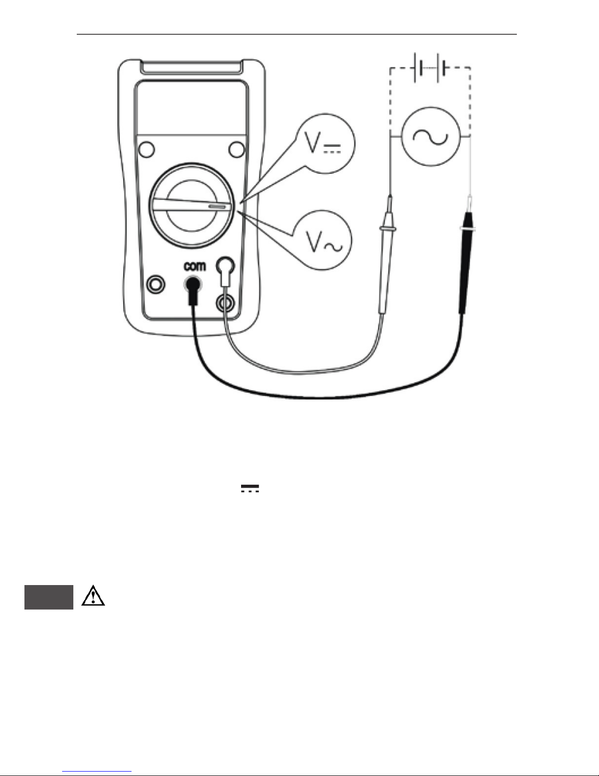
I. DC or AC voltage measurement (see diagram 2)
1) Turn rotary switch to V~ or V voltage measurement.
2) Insert the red test lead into the “V” terminal and the black test
lead into the “COM” terminal, connect the lest leads across with the
object being measured. The measured value shows on the display
AC voltage measurement shows on true root mean square value
stability period.
3) In each range, the meter has an input impedance of 10M . V~
input impedance is about 4.5M . This loading effect can cause
measurement errors in high impedance circuits. If the circuit impedance is less than or equal to 10k , the error is negligible (0.1%
or less).
Warning:
• To avoid possibly damages to the meter, please do not attempt to input higher than 600V.
• To avoid electrical shock, please pay attention during the
high voltage measurement.
Page 8
Owner’s manual
8
EN
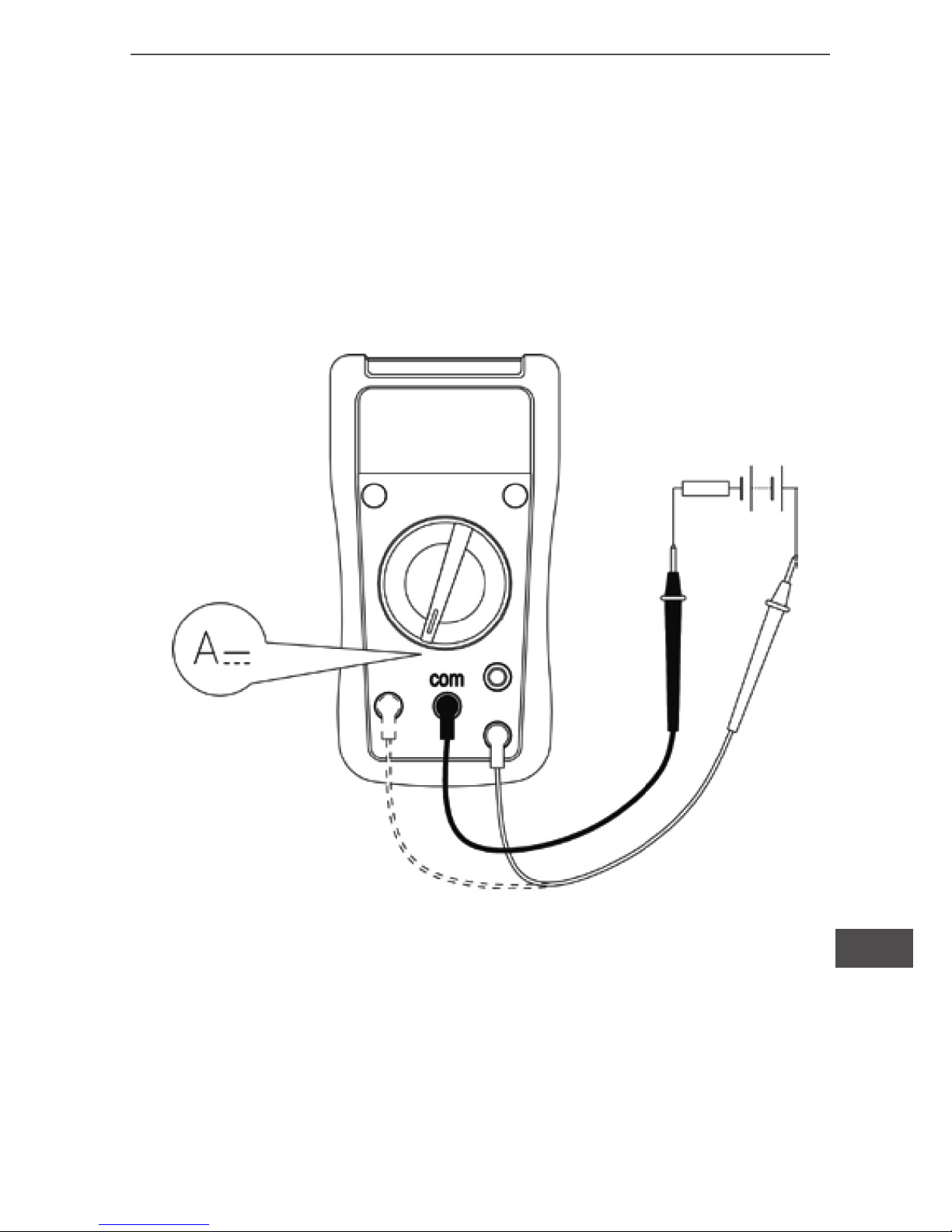
II. DC current measurement (see diagram 3)
1) Turn rotary switch to A current measurement.
2) Insert the red test lead into the „ mA” or ”10A” terminal, and the
black test lead into the „COM” terminal, Connect the test leads
across with the object being measured. The measured value
shows on the display.
Warning:
• Pre-requisites: Turn off power to the circuit before the connection between the test leads across with the object being
measured.
• Selecting the correct terminal input and turn the rotary
switch to select the measuring function. In case of no any idea
on the value input of the current, just simply test from the high
value to low one.
Diagram 2
Page 9
9
Owner’s manual
EN
• Fuses are located on mA and 10A terminal input.
Never attempt the test lead connect to any circuits especially
on the power supply terminal and may be hurt.
• For the safety purpose, less than 10 seconds is for each
measurement duration and keep 15 minutes duration for next
measurement during the current measurement over 5A.
Diagram 3
Page 10

Owner’s manual
10
EN
Warning:
• The LCD displays „1” indicating open-circuit for the tested
resistor or the resistor value is higher than the maximum
range of the meter.
• To maintain the resistance measurement accuracy, discount
circuit power and discharge all the high voltage capacitors
during the measuring resistance.
• For high-resistance measurement greater than 1M , it is
normal to take several seconds to obtain a stable reading with
short test leads for measurement.
• Do not input higher than DC 60V and AC 30V voltage to prevent any damage and accident.
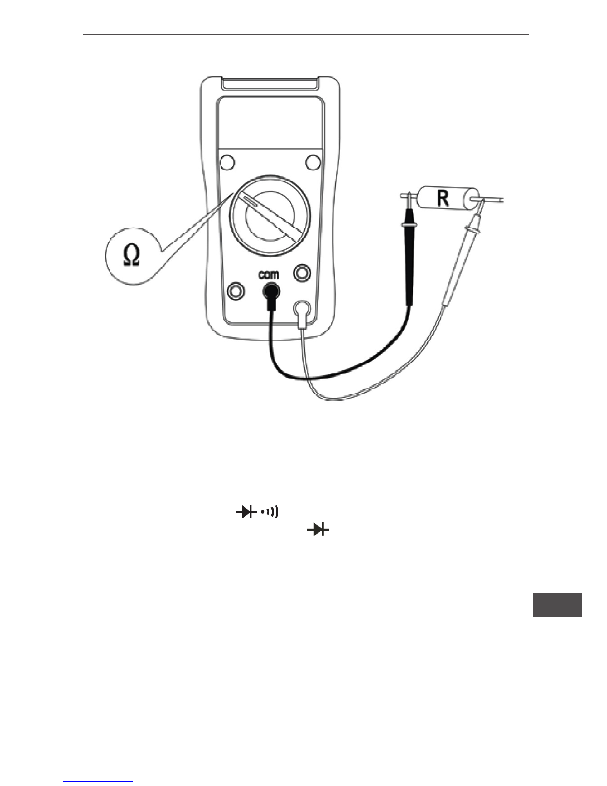
III. Resistance measurement (see diagram 4)
1)Turn rotary switch to “ ” ohm measurement.
2) Insert the red test lead into the “ ” terminal and the black test
lead into the “COM” terminal. Connect the test leads across with
the object being measured. The measured value shows on the
display.
Page 11
11
Owner’s manual
EN
Diagram 4
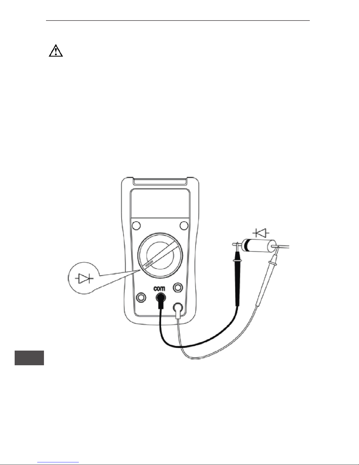
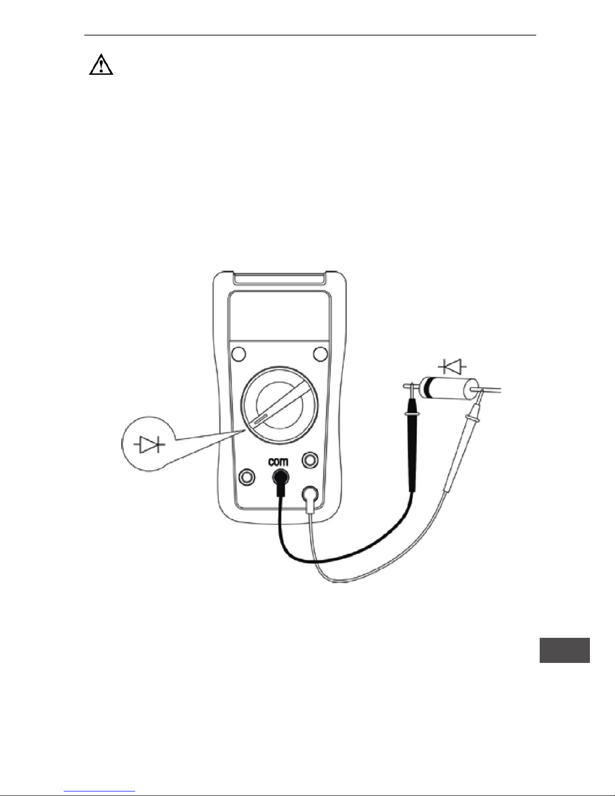
IV. Diodes measurement (see diagram 5)
1)Turn rotary switch to .
2) Insert the red test lead into the
terminal and the black test
lead into the “COM” terminal. Red test lead is “+” Black test lead is
“-”.
3) In a circuit, a good diode should still produce a forward voltage
drop reading of 500~800mV. However, the reverse voltage drop
reading can vary depending on the resistance of other pathways
between the probe tips.
Page 12
Owner’s manual
12
EN
Warning:
• The LCD displays “1” indicating open-circuit for the tested
diodes or the testing the diodes with polarity.
• To maintain the diodes measurement accuracy disconnect
circuit power and discharge all the high voltage capacitors
during the measuring resistance.
• Do not input higher than DC 60V and AC 30V voltage to prevent any damage and accident.
Diagram 5
Page 13
13
Owner’s manual
EN
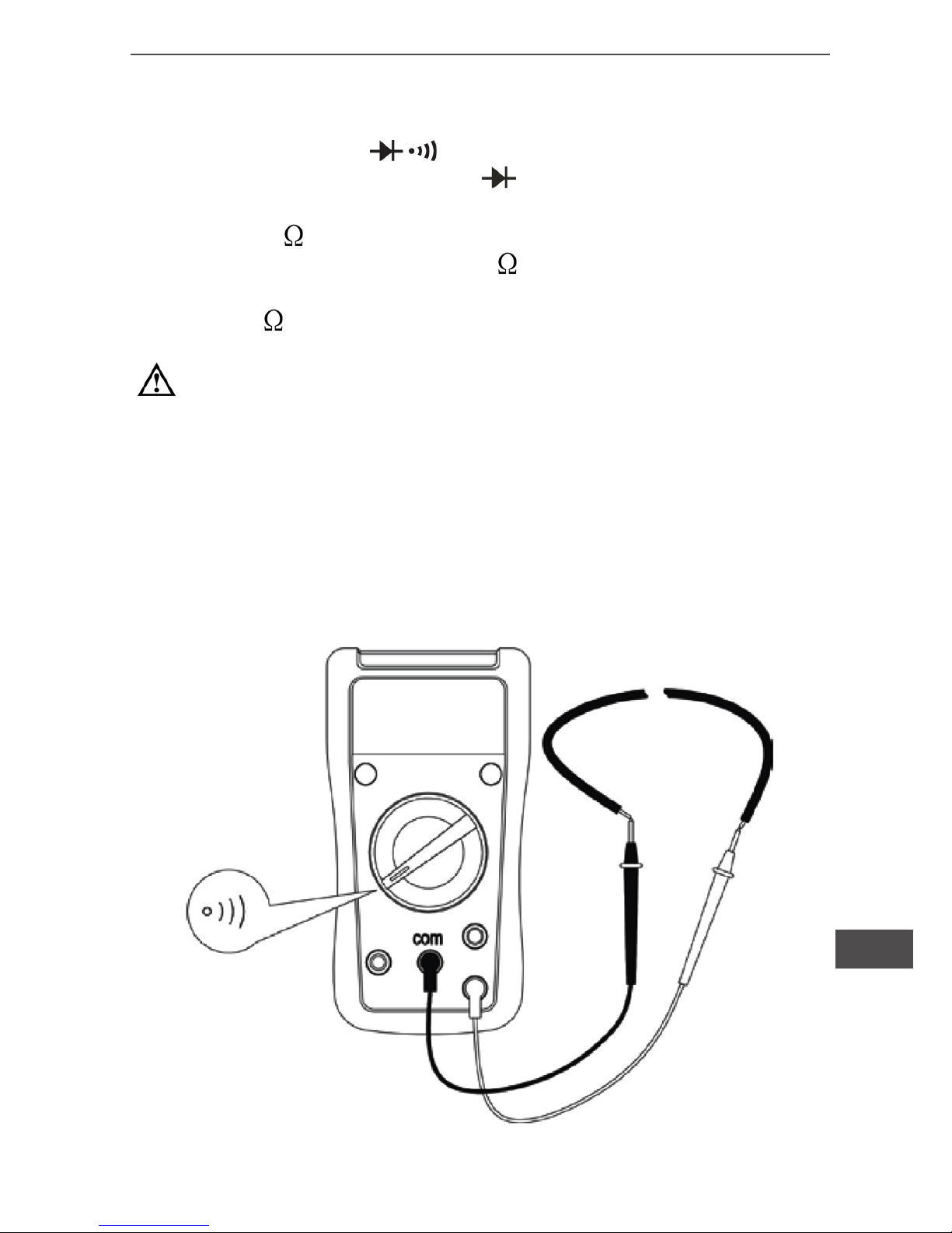
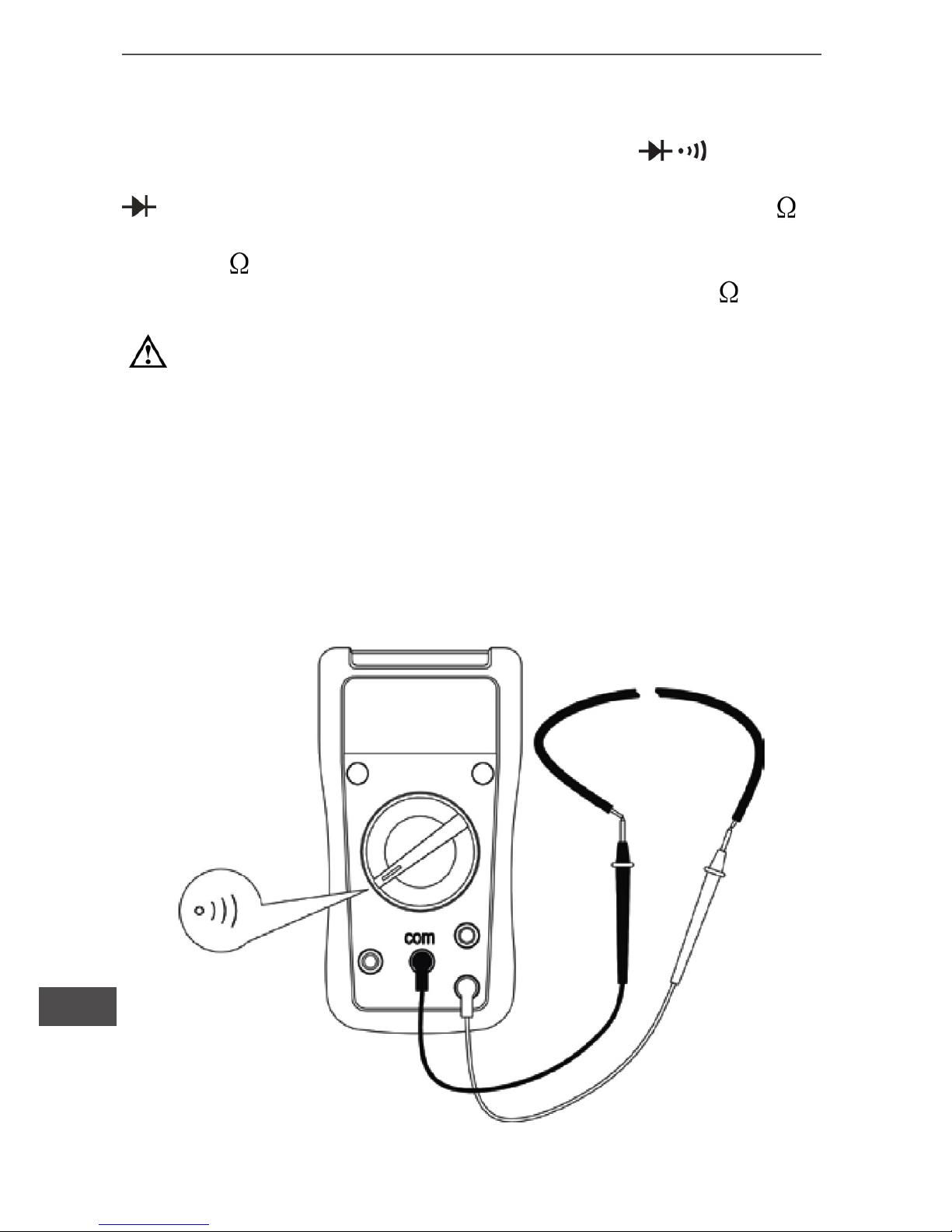
V. Continuity measurement (see diagram 6)
1)Turn rotary switch to .
2) Insert the red test lead into the terminal and the black test
lead into the “COM” terminal. If between both terminals show
resistance >70 , it is a short-circuit,no buzzer, but if between
both terminals show resistances 10 , it is a good connection with
continually buzzer. Resistance value on tested circuit display on
LCD (Unit is
).
Warning:
• To maintain the diodes measurement accuracy disconnect
circuit power and discharge all the high voltage capacitors
during the measuring resistance.
• Do not input higher than DC 60V and AC 30V voltage to prevent any damage and accident.
Diagram 6
Page 14
Owner’s manual
14
EN
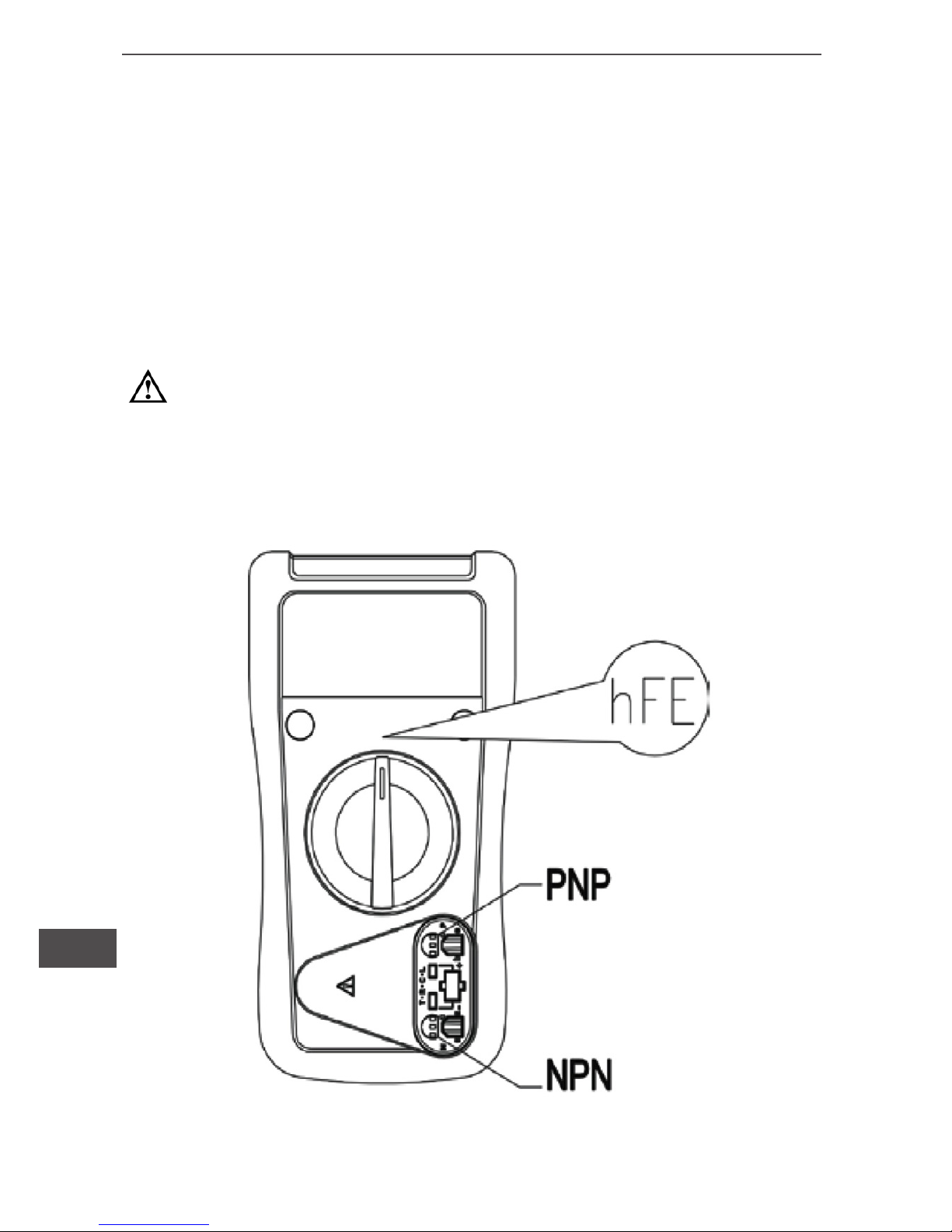
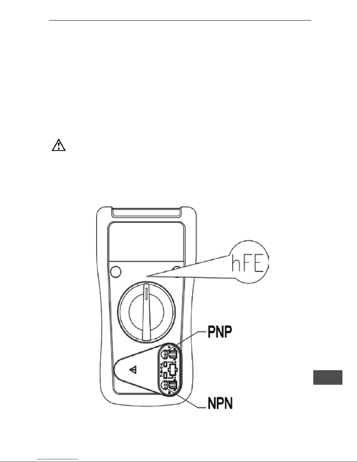
VI. Transistor hFE measurement (see diagram 7)
1)Turn rotary switch to “hFE”.
2) Put the muItiple purpose socket into the terminal.
3) Check the transistor is either PNP or NPN, assembles or SMT,
then connect the transistor to be measured to the corresponding
jacks.
4) LCD display hFE reference value. The testing requirement:
basic current 10μA,Vce for 2.3V.
Warning:
• To avoid damages to the Meter or to the devices under test,
do not input any current over 60V DC or 30V AC.
• Take off the multi-purpose socket after the measurement.
Diagram 7
Page 15
15
Owner’s manual
EN
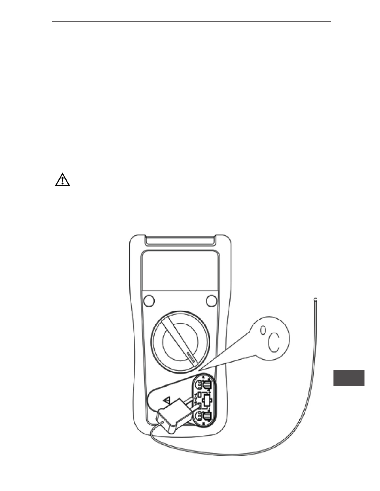
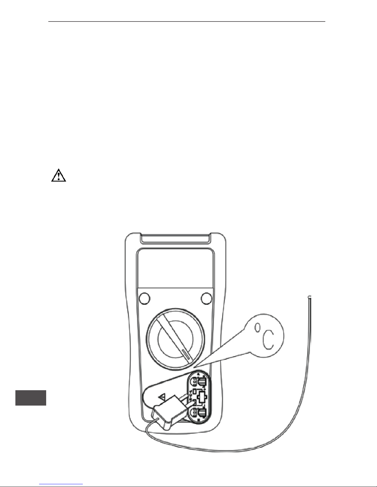
VII. Temperature measurement (for MIE0142 onIy),
see diagram 8.
1) Turn rotary switch to “0C”.
2) Put the multiple purpose socket into the correct terminal.
3) K—Type point contact temperature probe can only be used in
the measurement below 2300C, if you want to measure over 2300C,
you need to separately buy another temperature probe.
4) The LCD displays “1” indicating point contact temperature probe
which take off. When short circuit between, terminal and COM
terminal, the meter show the value of room temperature.
Warning:
• Maintain clean the point contact temperature probe and do
not let the probe contact point to have any serious inuence.
• Take off and well keep the point contact temperature after the
measurement.
Diagram 8
Page 16
Owner’s manual
16
EN
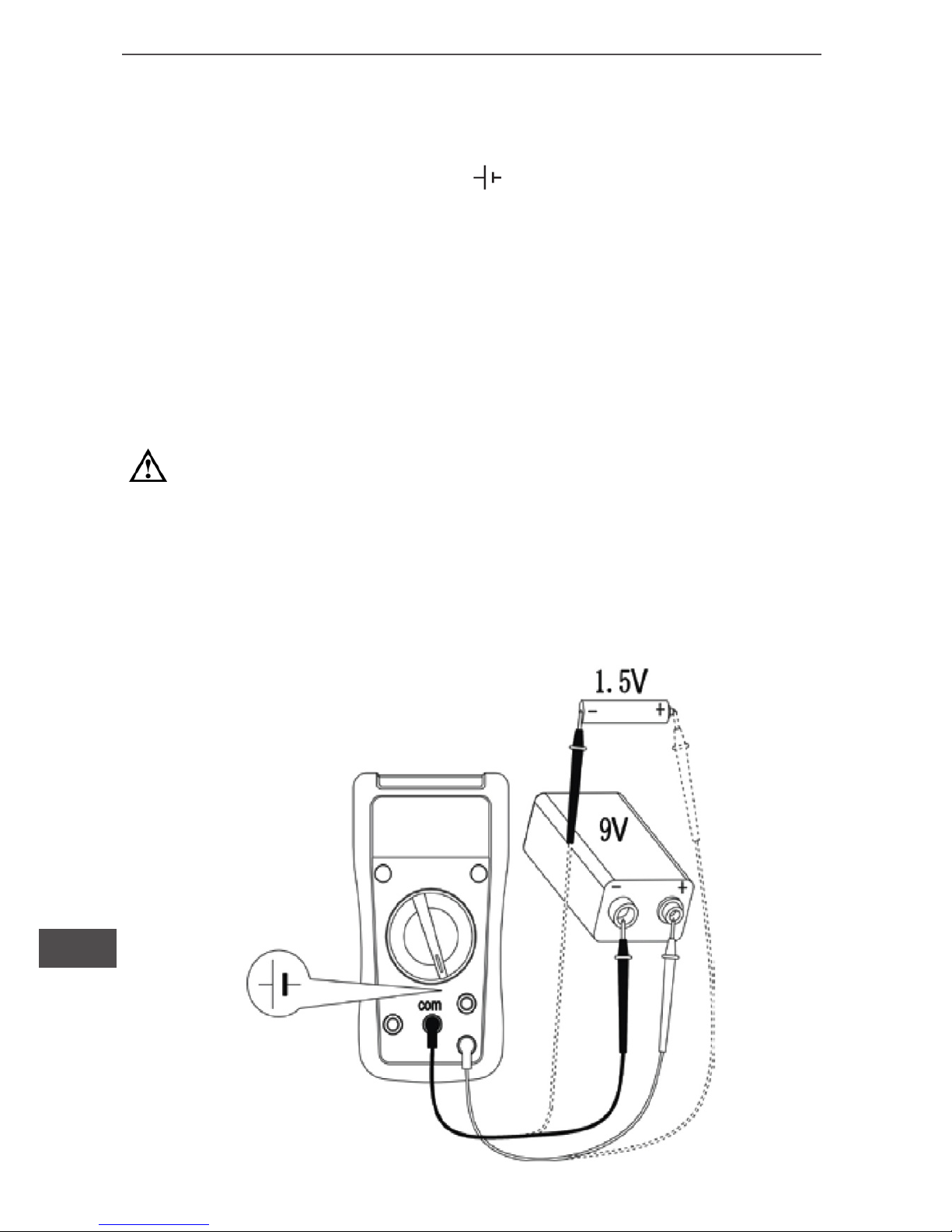
VIII. Battery test (MIE0141 onIy), see diagram 9.
1)Turn rotary switch to 1.5V or 9V.
2) Insert the red test lead into the
terminal and the black test
lead into the “COM” terminal. Red test lead is “+”, black test lead is
“-”. Connect the test leads across with the battery being measured
ensuring the polarity is correct. The measured value shows on the
display, which is the voltage between the cathode and anode of the
battery.
3) 1.5V usage ≤1.5V dry cell battery test, resistance load is approximately for 15Ω; 9V is only suitable for ≤15V dry cell battery
test, resistance load is approximately for 1kΩ.
Warning:
• Refuse to keep a long time connection battery in the measuring process, it avoids to loss the battery energy, to reduce
battery’s life.
• Refuses to use in over the specication of the battery or the
current test, in order to avoid damages the measuring appliance and endangers the personal safety!
Diagram 9
Page 17
17
Owner’s manual
EN
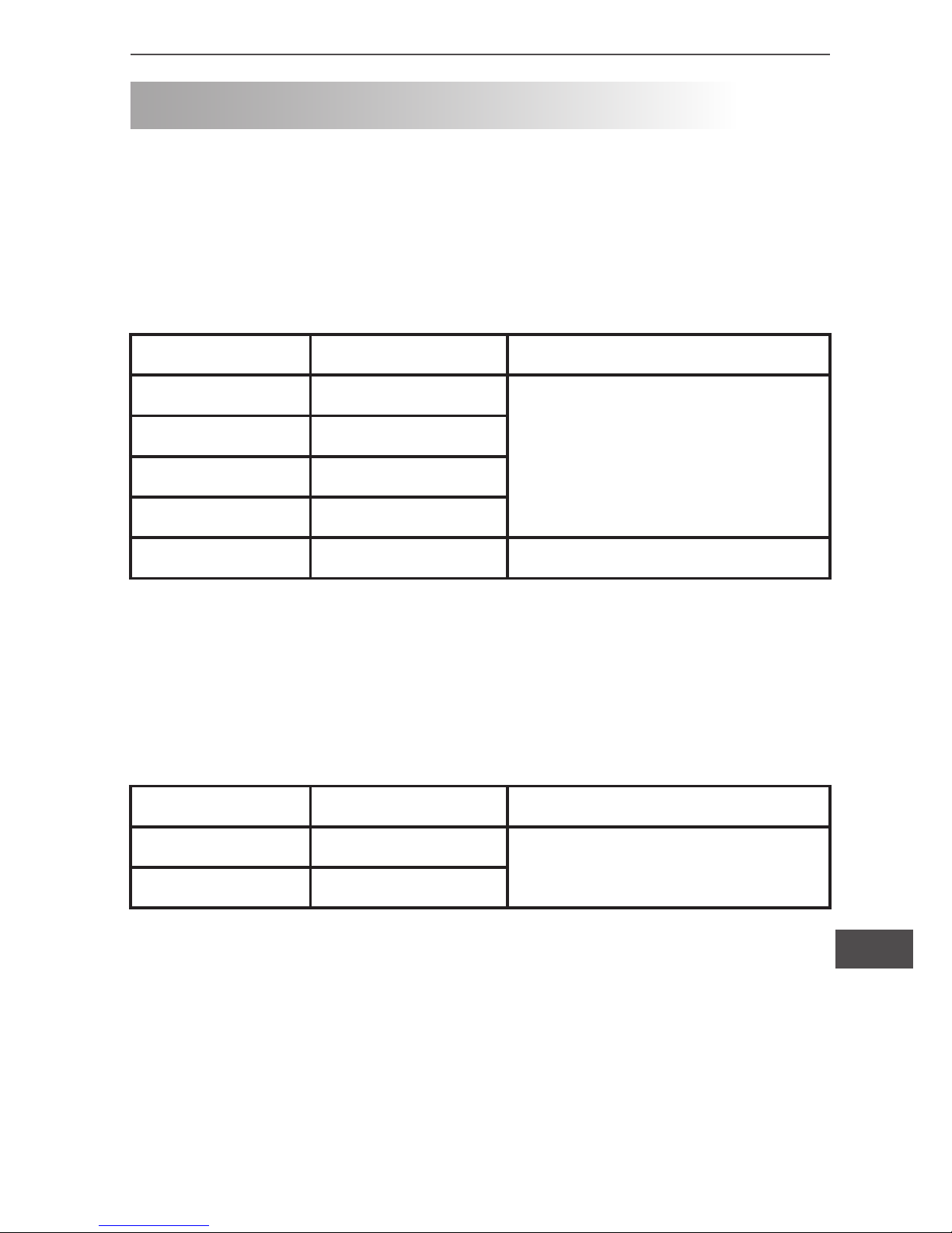
ACCURACY SPECIFICATION
Accuracy: ± (a% reading + b digits) guarantee for 1 year
Operating temperature: 230C ±50C
Relative humidity: <75%
1. DC voltage
Range Resolution Accuracy
200mV 0.1mV ±(0.5% + 2)
2V 1mV
20V 10mV
200V 100mV
600V 1V ±(0.8% + 2)
● Input impedance: 10MΩ
● Maximum input voltage: 600V DC
2. AC voltage
Range Resolution Accuracy
200V 0.1mV ±(1.2% + 3)
600V 1mV
● Input impedance: about 4.5MΩ
● Frequency: 45Hz ~ 400Hz
● Display: effective value of sine wave (average value) each measurement is applicable from 5% of range as reference.
● Maximum input voltage: 600V AC.
Page 18
Owner’s manual
18
EN
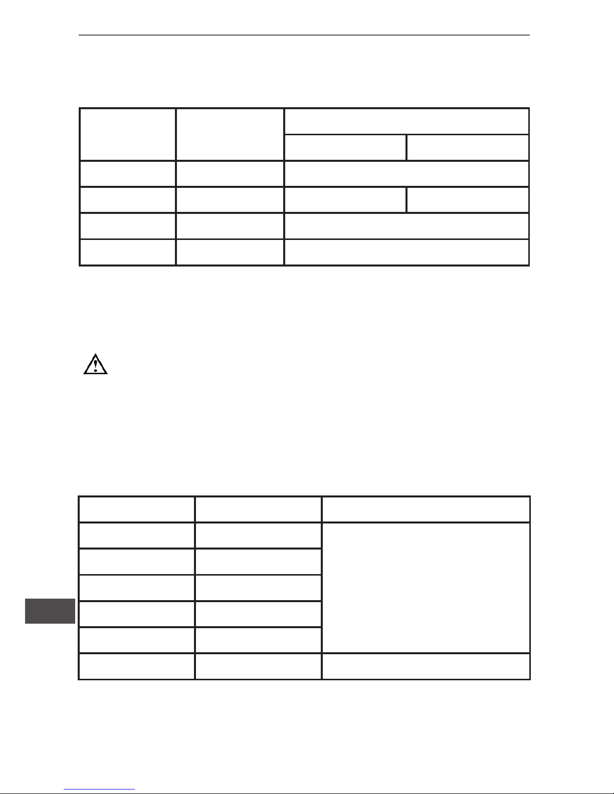
3. DC current
Range Resolution Accuracy
MIE0141 MIE0142
2000μA 0.1mV ±(1% + 2)
20mA 1mV ±(1% + 2) ---
200mA 10mV ±(1.2% + 2)
10A 100mV ±(2% + 5)
● Overload protection:
- mA range: F2 fuse φ6x25mm, F 1A H 250V (CE)
- 10A range: F1 fuse φ6x25mm, F 10A H 250V (CE)
Warning:
When ≤5A continuous measurement is allowed.
When > 5A continuous measurement less than 10 seconds at
an interval more than 15 minutes.
4. Resistance
Range Resolution Accuracy
200Ω 0.1Ω
±(0.8% + 5)
2kΩ 1Ω
20kΩ 10Ω
200kΩ 100Ω
2MΩ 1kΩ
20MΩ 10kΩ ±(1% + 5)
● Overload protection: 250V AC or DC
Page 19
19
Owner’s manual
EN
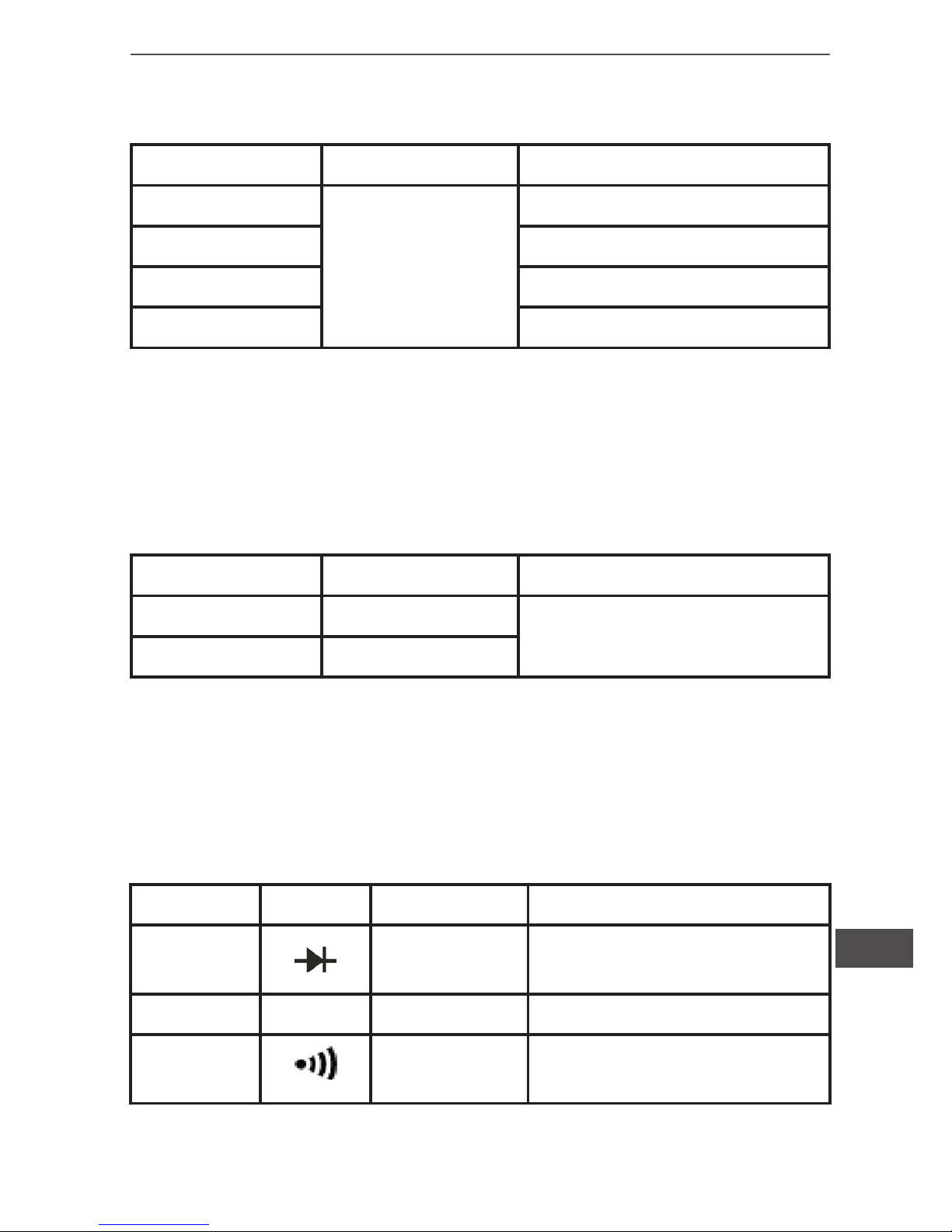
5. Temperature measurement (for MIE0142 only)
Range Resolution Accuracy
-40 ~ -20
0
C
1
0
C
±(8% + 5)
> -20 ~ 0
0
C ±4
> 0 ~ 100
0
C ±(1% + 3)
> 100 ~ 1000
0
C ±(2.5% + 2)
● Overload protection: 250V AC or DC.
● Enclosed point contact K type thermocouple can only be used on
less than 230
0
C temperature measurement.
6. Battery test (for MIE0141 only)
Range Resolution Accuracy
1.5V 1mV
±(1% + 2)
9V 10mV
● Overload protection: 250V AC or DC.
● 1.5V range: resistance load is about 15Ω.
● 9V range: resistance load is about 1kΩ.
7. Diode, transistor, continuity test
Function Range Resolution Accuracy
Diode
1mV
Display positive voltage
decline
Transistor hFE 1β
Continuity
test
1Ω
<1Ω buzzer beep continu-
ously
● Overload protection: 250V AC or DC.
Page 20

Owner’s manual
20
EN
MAINTENANCE AND SERVICE
Warning: Make sure the test leads take off the terminal
and the circuit as well as power off the meter if want to open
the meter cover.
1. General service and maintenance
• Periodically wipe the case with a damp cloth and mild detergent.
Do not use abrasives or solvents.
• Any abnormal on the meter, stop use the meter and return to
service center.
• When need to have calibration on the meter, please allow certied engineer or specic service center for the service maintenance.
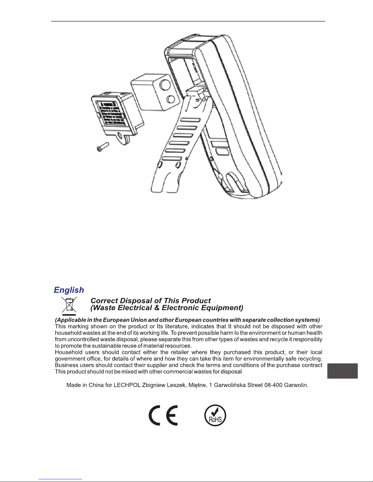
2. Replacing the battery and fuse, see diagram 9.
Warning: LCD display sign indicating battery will be
run out and need to replace a new battery, if fail to do that. It
causes the variance of the measuring result.
Battery specication: 9V BF22 or NEDA 1604 or 006P
Operating steps:
(1) Turn the power in “off“ situation, then remove the test lead out
of the meter.
(2) Use screwdriver to take off the screw on the battery cover. Then
you can take off old battery for replacing.
(3) User screwdriver to take off two pieces of screws, then you can
replacing the burned fuse(s) as replacement. Fuse specication:
- F1 fuse φ6x25mm, F 10A H 250V
- F2 fuse φ6x25mm, F 1A H 250V
Page 21
21
Owner’s manual
EN
Diagram 9
Specications are subject to change without notice.
Page 22

Instrukcja obsługi
22
PL
WSTĘP
Uwaga
Aby uniknąć porażenia prądem elektrycznym lub innych uszkodzeń
ciała, należy uważnie przeczytać i przestrzegać poniższych zasad:
● Przed użyciem miernika należy sprawdzić obudową, czy nie posiada uszkodzeń, jest zamknięta i skręcona wkrętami.
● Należy sprawdzić przewody pomiarowe, czy nie mają uszkodzeń
izolacji.
● Nigdy nie wolno używać miernika, jeżeli napięcie płynące w mierzonym obwodzie jest wyższe niż maksymalne napięcie dla danego modelu miernika.
MIE0141/MIE0142 z cyfrowym wyświetlaczem 3 1/2, charakteryzuje się dużą ilością funkcji, prostotą i wygodą użytkowania oraz niezawodnością działania. Miernik przeznaczony jest do pomiaru napięcia prądu stałego i zmiennego, natężenia prądu stałego, rezystancji, diod, ciągłości obwodu, hFE, temperatury (MIE0142), baterii (MIE0141) itp. Przed pierwszym użyciem miernika, należy dokładnie przeczytać instrukcję obsługi i stosować się do wszystkich
zaleceń i informacji w niej zawartych. Instrukcję należy zachować
w celu późniejszego wykorzystania.
Uwaga: Aby uniknąć porażenia prądem elektrycznym, należy dokładnie i ze zrozumieniem przeczytać rozdział „Zasady bezpieczeństwa” oraz stosować się do zaleceń w nim zawartych.
ZASADY BEZPIECZEŃSTWA
Page 23

23
Instrukcja obsługi
PL
● Po zakończonym pomiarze należy odłączyć przewody pomiarowe od mierzonego obiektu, odpiąć je od miernika i wyłączyć miernik.
● Obrotowy przełącznik powinien być ustawiony we właściwej pozycji przed dokonaniem pomiaru (nie należy go przekręcać w trakcie pomiaru).
● Nie należy używać miernika, jeżeli tylna obudowa i pokrywa baterii nie jest całkowicie zamknięta.
● Należy zachować szczególną ostrożność przy pomiarach, gdzie
napięcie ma wartość powyżej 60V DC lub 30V AC.
● Należy dostosować położenie przełącznika obrotowego oraz
sposób pomiaru do danego rodzaju pomiaru.
● Nie należy używać i przechowywać miernika w miejscach o dużej wilgotności powietrza, wysokiej temperaturze lub silnym polu
elektromagnetycznym.
● Używając przewodów pomiarowych należy pamiętać, aby palce
znajdowały się za osłoną ochronną.
● Należy wyłączyć zasilanie z mierzonego obwodu i rozładować
wysokonapięciowe kondensatory przed pomiarem natężenia prądu, rezystancji lub przed sprawdzaniem diod.
● Baterię należy wymienić na nową niezwłocznie po pojawieniu się
symbolu “
” na wyświetlaczu.
● Jeżeli podczas serwisowania miernika zachodzi konieczność wymiany elementu, to należy go wymienić na identyczny z oryginałem.
● Nie wolno dokonywać żadnych zmian wewnątrz miernika.
Page 24

Instrukcja obsługi
24
PL
● Do czyszczenia obudowy miernika należy używać wyłącznie
miękkiej ściereczki i delikatnego detergentu (nie należy stosować
silnych środków czyszczących).
● Miernik przeznaczony jest do użytku wewnątrz pomieszczeń.
● Po zakończeniu pomiarów, należy wyłączyć miernik. Jeżeli miernik nie będzie używany przez dłuższy okres czasu, należy wyjąć
baterię zasilającą.
● Należy okresowo sprawdzać stan zainstalowanej baterii. Cieknąca bateria może spowodować uszkodzenie miernika.
Page 25
25
Instrukcja obsługi
PL
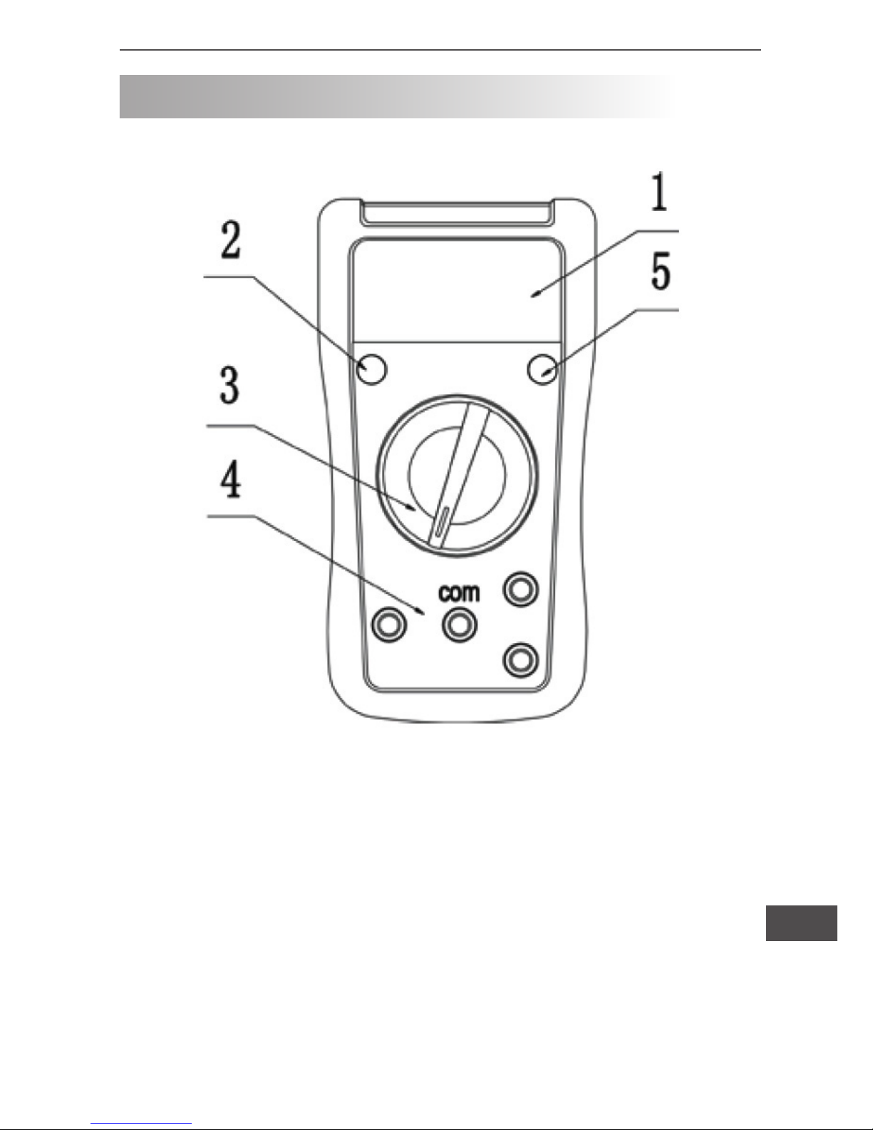
OPIS MIERNIKA
1. Wyświetlacz LCD
2. Przycisk Power (włączenie/wyłączenie miernika)
3. Przełącznik obrotowy
4. Gniazda wejściowe
5. Przycisk Hold
Diagram 1
Page 26
Instrukcja obsługi
26
PL
WYKONYWANIE POMIARÓW
W celu dokonania pomiaru, należy ustawić przełącznik obrotowy
we właściwej pozycji (w zależności od rodzaju pomiaru) a następ-
nie włączyć miernik. Jeżeli na wyświetlaczu ukaże się symbol
,
należy niezwłocznie wymienić baterię zasilania na nową. Nie należy dokonywać pomiarów w przypadku, gdy napięcie/natężenie prądu przekracza dopuszczalną dla miernika wartość.
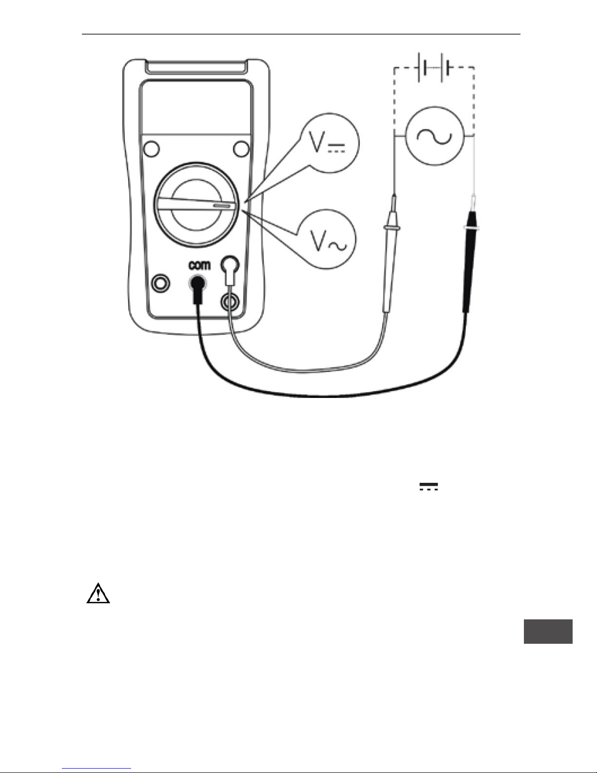
I. Pomiar napięcia DC lub AC (diagram 2)
1) Przełącznik obrotowy należy ustawić w pozycji V~ (prąd zmienny AC) lub V (prąd stały DC).
2) Czerwony przewód pomiarowy należy podłączyć do gniazda “V”,
czarny do gniazda “COM”. Następnie należy podłączyć przewody pomiarowe do mierzonego obiektu i odczytać wynik pomiaru na
wyświetlaczu.
3) W każdym zakresie miernik ma impedancję wejściową 10M .
Przy pomiarze V~ impedancja wynosi około 4.5M . Może to powodować błędy pomiaru w obwodach wysokiej impedancji. Jeśli impedancja obwodu jest mniejsza lub równa 10k , błąd jest nieznaczny (0,1% lub mniej).
Uwaga:
• Aby uniknąć uszkodzenia miernika, nie należy dokonywać
pomiaru, gdy wartość napięcia przekracza 600V.
• Aby uniknąć porażenia prądem, należy zwracać szczególną
uwagę podczas pomiaru wysokich napięć.
Page 27
27
Instrukcja obsługi
PL
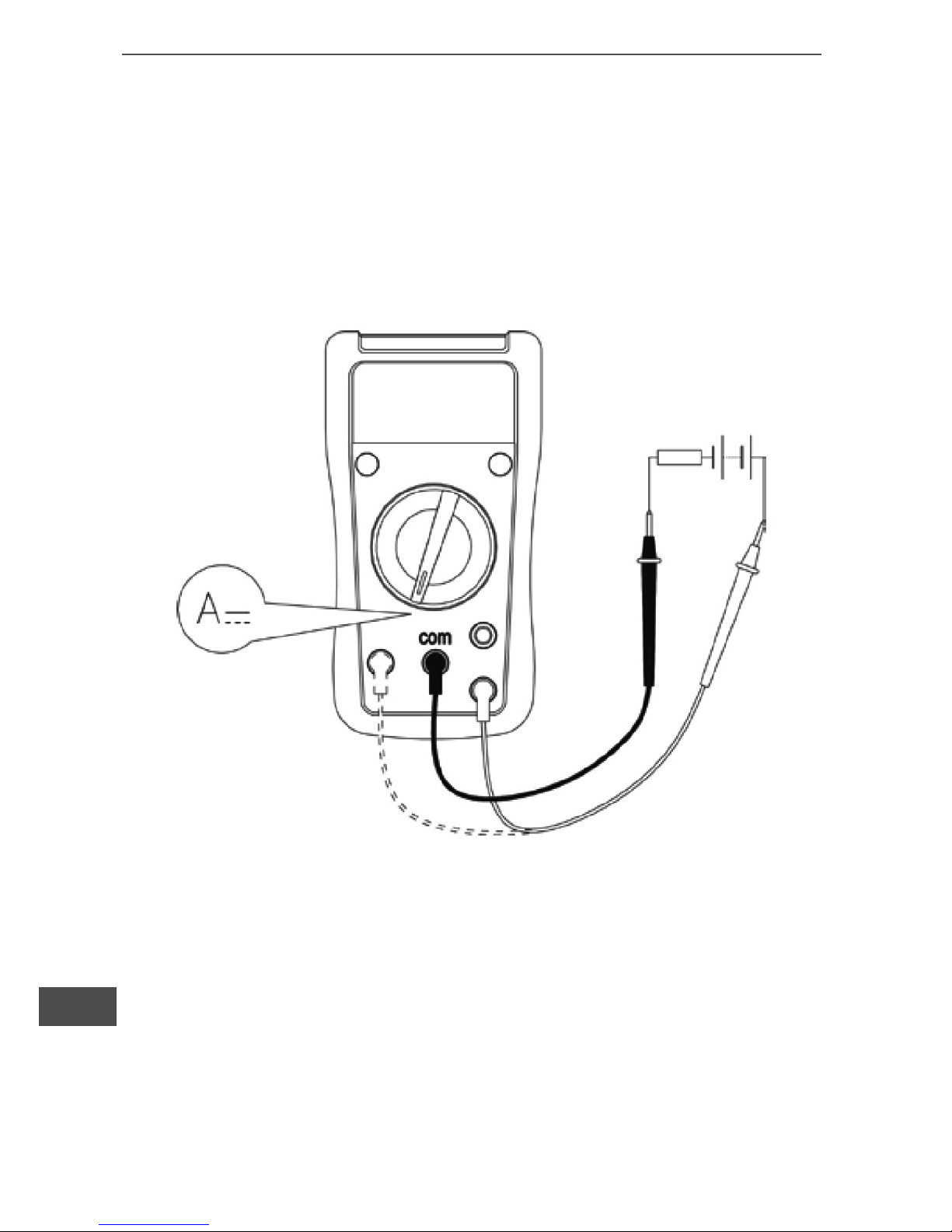
II. Pomiar natężenia prądu DC (diagram 3)
1) Przełącznik obrotowy należy ustawić w pozycji A .
2) Czerwony przewód pomiarowy należy podłączyć do gniazda
„mA” lub „10A”, czarny do gniazda “COM”. Następnie należy podłączyć przewody pomiarowe do mierzonego obiektu i odczytać wynik
pomiaru na wyświetlaczu.
Uwaga:
• Przed rozpoczęciem pomiaru należy wyłączyć zasilanie mierzonego obwodu.
• W zależności o mierzonej wartości należy wybrać odpowiednie gniazdo wejściowe oraz pozycję przełącznika obrotowego.
W przypadku wątpliwości, należy sprawdzić wartości od najwyższej do najniższej.
Diagram 2
Page 28
Instrukcja obsługi
28
PL
• Bezpieczniki są zlokalizowane w gniazdach wejściowych mA
oraz 10A.
• Ze względów bezpieczeństwa, przy pomiarach natężenia prądu ponad 5A, czas trwania pomiaru nie powinien przekraczać
10 sekund z 15 minutowymi przerwami pomiędzy kolejnymi
pomiarami.
Diagram 3
Page 29

29
Instrukcja obsługi
PL
Uwaga:
• Wartość „1” na wyświetlaczu oznacza obwód otwarty lub
wartość przekraczająca zakres miernika.
• Aby zachować dokładność pomiaru, przed jego rozpoczęciem należy odłączyć urządzenie od źródła zasilania oraz rozładować wysokonapięciowe kondensatory.
• W przypadku pomiaru rezystancji o wartości przekraczającej
1M , może zajść konieczność odczekania kilku sekund w celu
otrzymania stabilnego odczytu.
• Nie należy dokonywać pomiarów jeżeli napięcie przekracza
60V DC lub 30V AC.
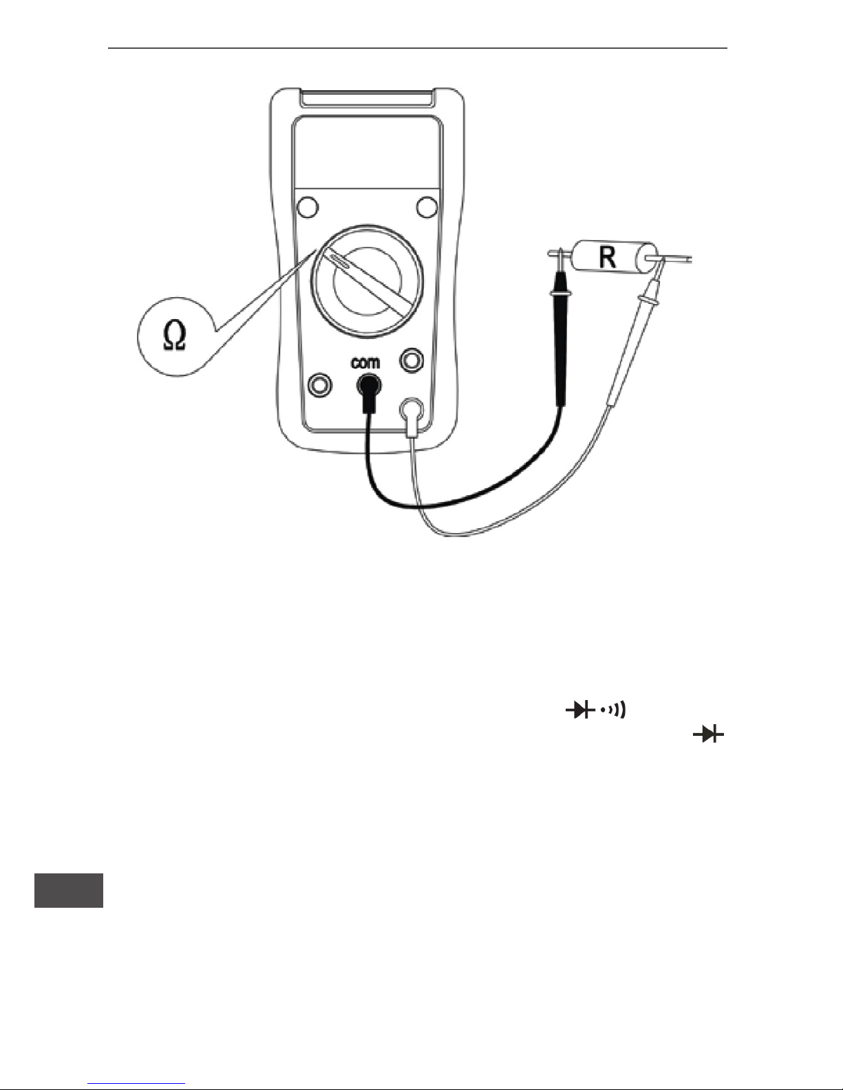
III. Pomiar rezystancji (diagram 4)
1) Przełącznik obrotowy należy ustawić w pozycji “ ”.
2) Czerwony przewód pomiarowy należy podłączyć do gniazda
„
”, czarny do gniazda “COM”. Następnie należy podłączyć przewody pomiarowe do mierzonego obiektu i odczytać wynik pomiaru
na wyświetlaczu.
Page 30
Instrukcja obsługi
30
PL
Diagram 4
IV. Test diod (diagram 5)
1) Przełącznik obrotowy należy ustawić w pozycji .
2) Czerwony przewód pomiarowy należy podłączyć do gniazda
czarny do gniazda “COM”. Czerwony przewód to “+”, czarny “-”.
3) W obwodzie, dobra dioda powinna generować wsteczne napięcie w zakresie 500 ~ 800mV. Wartość ta może się jednak zmieniać
w zależności od oporu innych ścieżek między końcówkami próbnika.
Page 31
31
Instrukcja obsługi
PL
Uwaga:
• Wartość „1” na wyświetlaczu oznacza obwód otwarty lub testowanie diod z polaryzacją.
• Aby zachować dokładność pomiaru, przed jego rozpoczęciem należy odłączyć urządzenie od źródła zasilania oraz rozładować wysokonapięciowe kondensatory.
• Nie należy dokonywać pomiarów jeżeli napięcie przekracza
60V DC lub 30V AC.
Diagram 5
Page 32
Instrukcja obsługi
32
PL
V. Test ciągłości obwodu (diagram 6)
1) Przełącznik obrotowy należy ustawić w pozycji .
2) Czerwony przewód pomiarowy należy podłączyć do gniazda
, czarny do gniazda “COM”. Wartość rezystancji powyżej 70
i brak sygnału dźwiękowego oznacza zwarcie, wartość rezystancji
poniżej 10 i ciągły sygnał dźwiękowy oznacza prawidłowe połączenie. Wyświetlana na ekranie wartość wyrażana jest w .
Uwaga:
• Aby zachować dokładność pomiaru, przed jego rozpoczę-
ciem należy odłączyć urządzenie od źródła zasilania oraz rozładować wysokonapięciowe kondensatory.
• Nie należy dokonywać pomiarów jeżeli napięcie przekracza
60V DC lub 30V AC.
Diagram 6
Page 33
33
Instrukcja obsługi
PL
VI. Pomiar hFE tranzystora (diagram 7)
1) Przełącznik obrotowy należy ustawić w pozycji “hFE”.
2) Do gniazd wejściowych miernika należy podłączyć przejściówkę
pomiarową.
3) W zależności od rodzaju, tranzystor należy podłaczyć do
przejściówki pomiarowej w odpowiedni sposób.
4) Na ekranie wyświetlana jest wartość referencyjna hFE.
Wymagane 10μA,Vce dla 2.3V.
Uwaga:
• Nie należy dokonywać pomiarów jeżeli napięcie przekracza
60V DC lub 30V AC.
Diagram 7
Page 34
Instrukcja obsługi
34
PL
VII. Pomiar temperatury (MIE0142), diagram 8.
1) Przełącznik obrotowy należy ustawić w pozycji “0C”.
2) Do gniazd wejściowych miernika należy podłączyć przejściów-
kę pomiarową do której następnie należy podłączyć czujnik pomiaru temperatury.
3) Znajdujący się w zestawie czujnik służy do pomiaru temperatury
nie przekraczającej 2300C. Do pomiaru wyższych temperatur należy dokupić dodatkowy czujnik.
4) Wartość “1” na wyświetlaczu, oznacza odłączenie punktu pomia-
rowego od czujnika.
Uwaga:
• Należy zapobiegać wszelkim zabrudzeniom końcówki czujni-
ka temperatury.
Diagram 8
Page 35
35
Instrukcja obsługi
PL
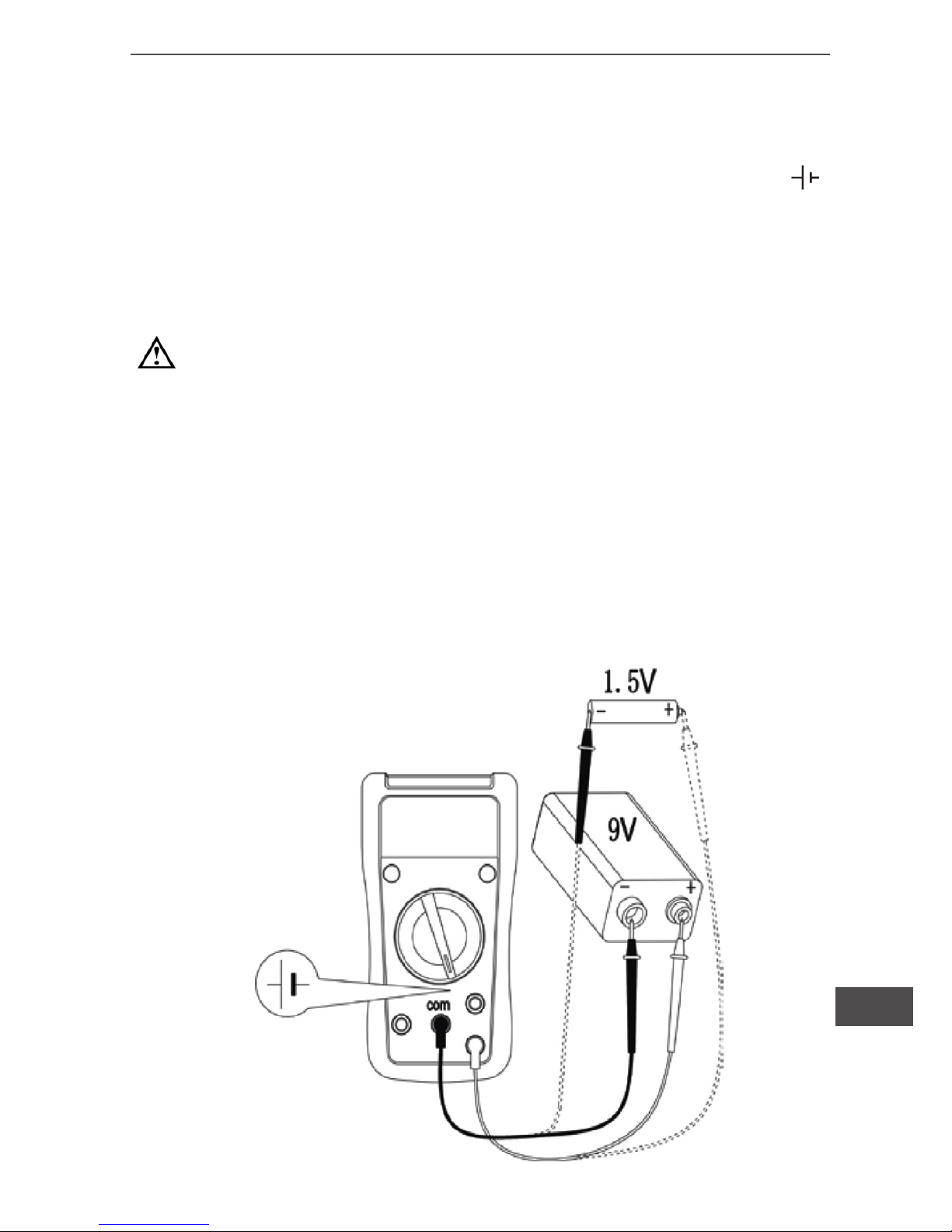
VIII. Test baterii (MIE0141), diagram 9.
1) Przełącznik obrotowy należy ustawić w pozycji 1.5V lub 9V.
2) Czerwony przewód pomiarowy należy podłączyć do gniazda
czarny do gniazda “COM”. Czerwony przewód to “+”, czarny “-”.
Następnie należy podłączyć przewody pomiarowe do mierzonej
baterii i odczytać wynik pomiaru na wyświetlaczu.
Uwaga:
• Należy unikać długotrwałych pomiarów baterii, powoduje to
utratę energii akumulatora i zmniejsza jego żywotność.
• Nie należy mierzyć innych typów baterii niż określone w specykacji.
Diagram 9
Page 36
Instrukcja obsługi
36
PL
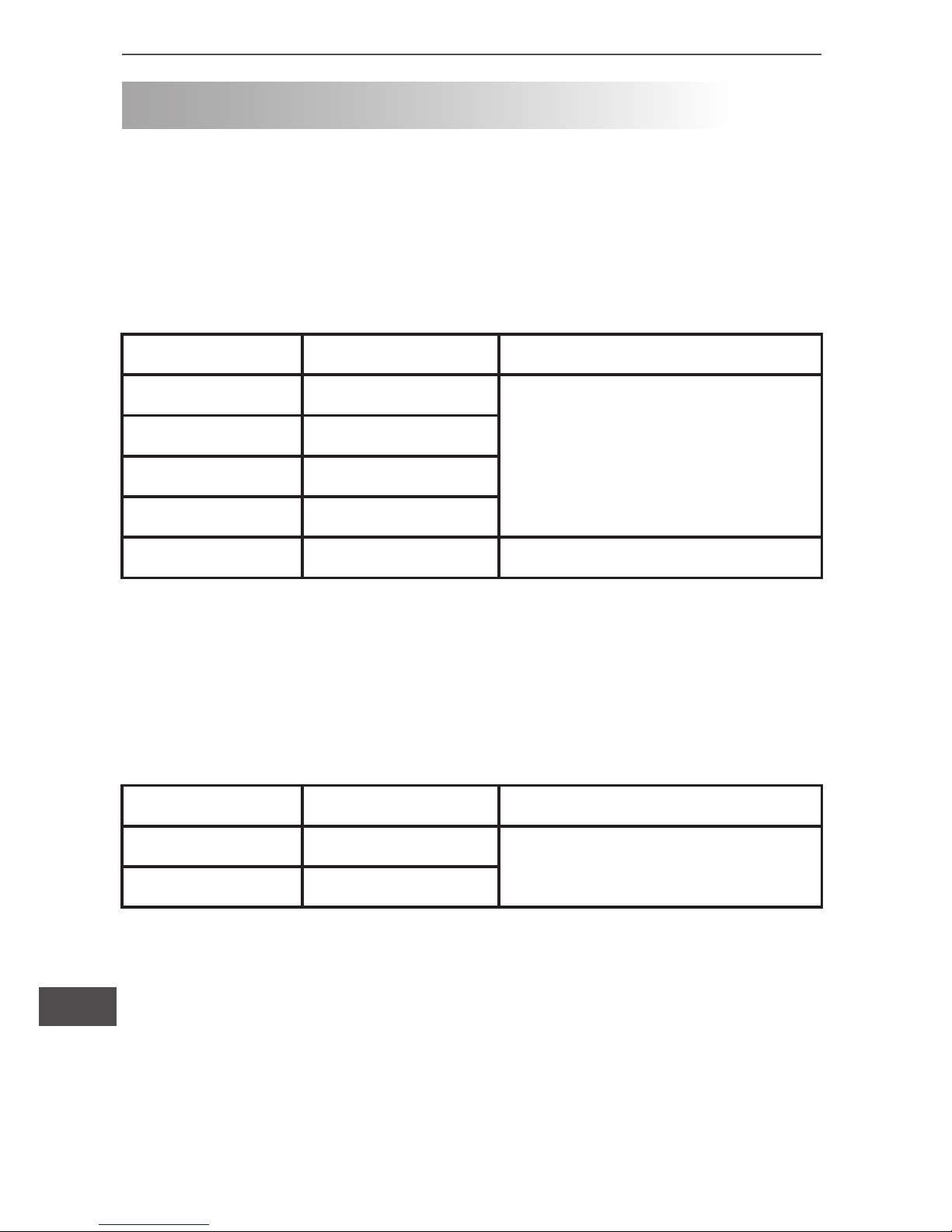
DOKŁADNOŚĆ POMIARÓW
Dokładność: ±(a% odczytu + b cyfr), gwarantowana przez 1 rok.
Temperatura pracy: 230C ±50C
Względna wilgotność: ≤75%R.H
1. Pomiar napięcia DC
Zakres Rozdzielczość Dokładność
200mV 0.1mV ±(0.5% + 2)
2V 1mV
20V 10mV
200V 100mV
600V 1V ±(0.8% + 2)
● Impedancja wejściowa: 10MΩ
● Maksymalne napięcie wejściowe: 600V DC
2. Pomiar napięcia AC
Zakres Rozdzielczość Dokładność
200V 0.1mV ±(1.2% + 3)
600V 1mV
● Impedancja wejściowa: około 4.5MΩ
● Częstotliwość: 45Hz ~ 400Hz
● Maksymalne napięcie wejściowe: 600V AC.
Page 37
37
Instrukcja obsługi
PL
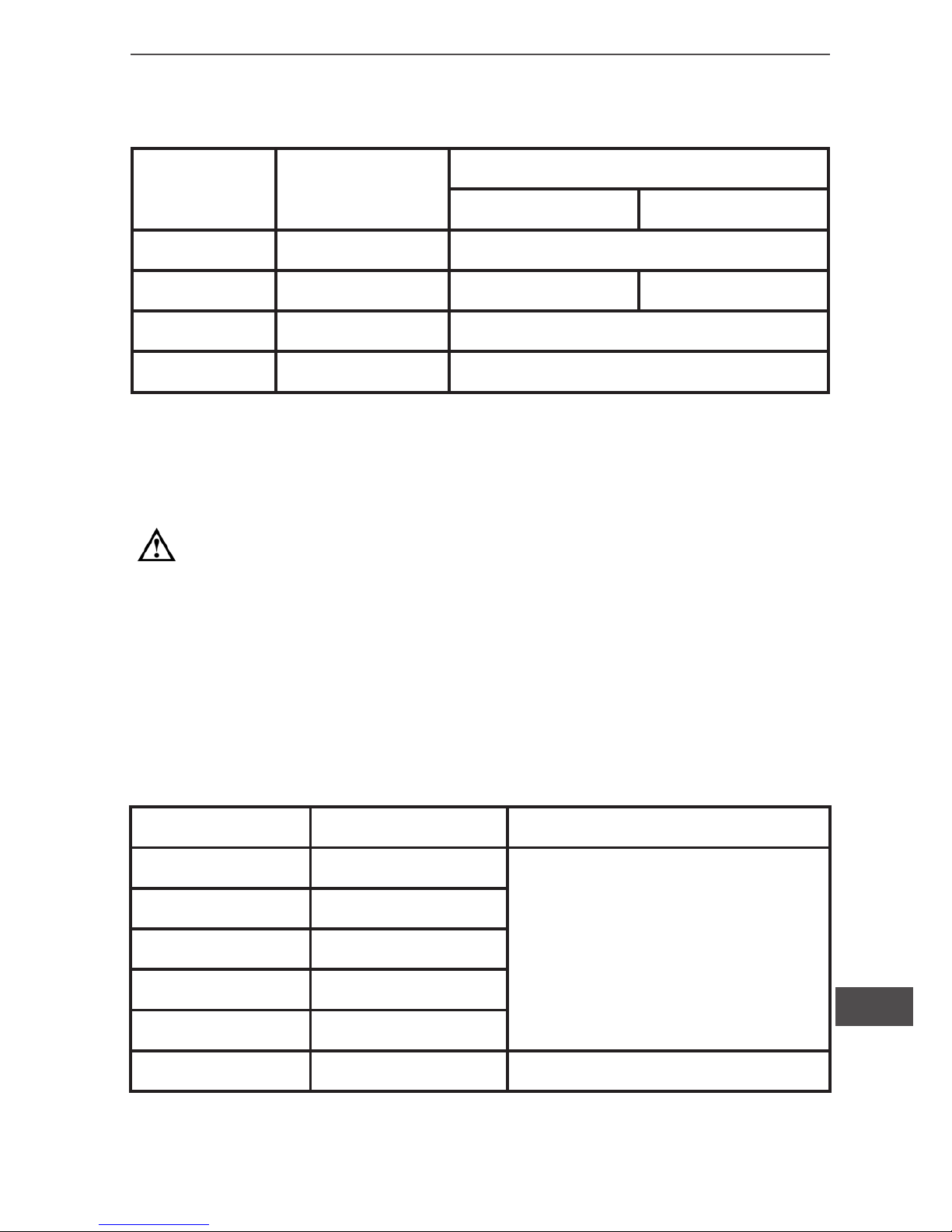
3. Pomiar natężenia prądu DC
Zakres Rozdzielczość Dokładność
MIE0141 MIE0142
2000μA 0.1mV ±(1% + 2)
20mA 1mV ±(1% + 2) ---
200mA 10mV ±(1.2% + 2)
10A 100mV ±(2% + 5)
● Zabezpieczenie przed przeciążeniem:
- zakres mA: bezpiecznik F2 φ6x25mm, F 1A H 250V (CE)
- zakres 10A: bezpiecznik F1 φ6x25mm, F 10A H 250V (CE)
Uwaga:
W przypadku pomiaru natężenia prądu o wartości ≤5A dozwolony jest pomiar ciągły.
W przypadku pomiaru natężenia prądu o wartości > 5A czas
trwania pomiaru nie powinien przekraczać 10 sekund z 15 minutowymi przerwami pomiędzy kolejnymi pomiarami.
4. Pomiar rezystancji
Zakres Rozdzielczość Dokładność
200Ω 0.1Ω
±(0.8% + 5)
2kΩ 1Ω
20kΩ 10Ω
200kΩ 100Ω
2MΩ 1kΩ
20MΩ 10kΩ ±(1% + 5)
● Zabezpieczenie przed przeciążeniem: 250V AC / DC
Page 38
Instrukcja obsługi
38
PL
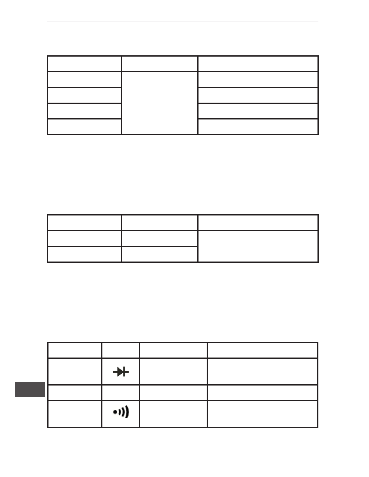
5. Pomiar temperatury (MIE0142)
Zakres Rozdzielczość Dokładność
-40 ~ -20
0
C
1
0
C
±(8% + 5)
> -20 ~ 0
0
C ±4
> 0 ~ 100
0
C ±(1% + 3)
> 100 ~ 1000
0
C ±(2.5% + 2)
● Zabezpieczenie przed przeciążeniem: 250V AC / DC.
● Znajdujący się w zestawie czujnik służy do pomiaru temperatury
nie przekraczającej 230
0
C.
6. Test baterii (MIE0141)
Zakres Rozdzielczość Dokładność
1.5V 1mV
±(1% + 2)
9V 10mV
● Zabezpieczenie przed przeciążeniem: 250V AC / DC.
● 1.5V: rezystancja obciążenia wynosi około 15Ω.
● 9V: rezystancja obciążenia wynosi około 1kΩ.
7. Dioda, tranzystor, ciągłość obwodu
Funkcja Zakres Rozdzielczość Dokładność
Dioda
1mV
Wyświetla spadek na-
pięcia
Tranzystor hFE 1β
Ciągłość
obwodu
1Ω
<1Ω ciągły sygnał dźwię-
kowy
● Zabezpieczenie przed przeciążeniem: 250V AC / DC.
Page 39
39
Instrukcja obsługi
PL
KONSERWACJA
Uwaga: Przed zdjęciem pokrywy miernika, należy odłączyć przewody pomiarowe i wyłączyć miernik.
1. Ogólny serwis i konserwacja.
• Wszelkie zabrudzenia należy usuwać za pomocą wilgotnej ściereczki z delikatnym detergentem (nie należy używać silnych środków czyszczących).
• W przypadku nieprawidłowej pracy miernika lub jego uszkodzenia
należy skontaktować się z serwisem urządzenia. Nie należy próbować samodzielnie naprawiać miernika.
• Jeżeli zachodzi konieczność kalibracji miernika, należy skontaktować się z serwisem.
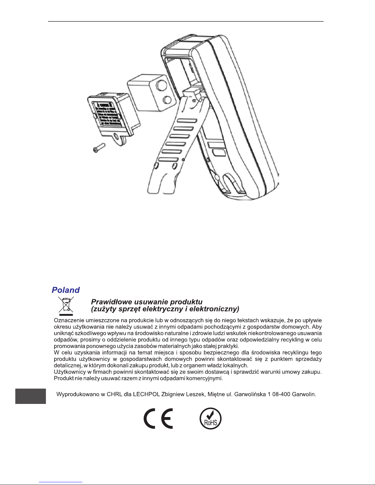
2. Wymiana baterii i bezpiecznika, diagram 9.
Uwaga: Baterię należy wymienić na nową niezwłocznie po
pojawieniu się symbolu “
” na wyświetlaczu.
Rodzaj baterii: 9V BF22
Aby wymienić baterię/bezpiecznik należy:
(1) Wyłączyć urządzenie i odpiąć przewody pomiarowe.
(2) Zdjąć pokrywę baterii, odkręcając wcześniej śrubę zabezpieczającą a następnie wymienić baterię na nową.
(3) Odkręcić dwie śruby zabezpieczające bezpieczniki i wymienić
spalony bezpiecznik na nowy. Specykacja bezpieczników:
- bezpiecznik F1 φ6x25mm, F 10A H 250V
- bezpiecznik F2 φ6x25mm, F 1A H 250V
Page 40
Instrukcja obsługi
40
PL
Diagram 9
Specykacja urządzenia może ulec zmianie bez powiadomienia.
Page 41

Page 42

www.uni-t.eu
 Loading...