

UNI-T MIE0141, MIE0142 Owner's Manual
Instrukcja obsługi
PL
Owner’s manual
EN
Palm size
digital
multimeter
MIE0141
MIE0142


3
Owner’s manual
EN
OVERVIEW
Warning
To avoid possible electric shock or personal injury, and to avoid
possible damage to the Meter or to the equipment under test,
adhere to the following rules:
● Before using the Meter inspect the case. Do not use the Meter if
it is damaged or the case (or part of the case) is removed. Look for
cracks or missing plastic. Pay attention to the insulation around the
connectors.
● Inspect the test leads for damaged insulation or exposed metal.
Check the test leads for continuity. Replace damaged test leads
with identical model number or electrical specications before using the Meter.
MIE0141/MIE0142 multimeter is a hand-held 3 1/2 digital display
digital multimeters with advanced design, multiple entire functions,
novel gurations and reliable performance. This meter is fully capable to measure voltage both AC and DC, DC current, resistance,
inductance, temperature and forward voltage drop of diode, tran-
sistor, hFE and continuity test etc. Please use multi-purpose socket
to measure SMT as well. This operating manual covers information
on safety and cautions to fulll CE mark standard. Please read the
relevant information carefully and observe all the warnings and
notes strictly.
Warning: To avoid electric shock or personal injury, read the
“Safety information” and „Rules for Safe Operation” carefully before
using the meter.
RULES FOR SAFE OPERATION

Owner’s manual
4
EN
● Do not apply more than the rated voltage, as marked on the
Meter.
● When measurement has been completed, disconnect the con-
nection between the test leads and the circuit under test and turn
the Meter power off.
● The rotary switch should be placed in the right position and no
any changeover of range shall be made during measurement is
conducted to prevent damage of the Meter.
● Do not carry out the measurement when the Meter’s back case
and battery compartment are not closed to avoid electric shock.
● When the Meter working at an effective voltage over 60V in DC
or 30V rms in AC, special care should be taken for there is danger
of electric shock.
● Use the proper terminals, function, and range for your measurements.
● Do not use or store the Meter in an environment of high temperature, humidity, explosive, inammable and strong magnetic eld.
The performance of the Meter may deteriorate after dampened.
● When using the test leads, keep your ngers behind the nger
guards.
● Disconnect circuit power and discharge all high-voltage capacitors before testing resistance, continuity and diode.
● Replace the battery as soon as the battery indicator appears.
With a low battery, the Meter might produce false readings that can
lead to electric shock and personal injury.
● When servicing the Meter, use only the same model number or
identical electrical specications replacement parts.

5
Owner’s manual
EN
● The internal circuit of the Meter shall not be altered at will to
avoid damage of the Meter and any accident.
● Soft cloth and mild detergent should be used to clean the surface
of the Meter when servicing. No abrasive and solvent should be
used to prevent the surface of the Meter from corrosion, damage
and accident.
● The Meter is suitable for indoor use.
● Turn the Meter off when it is not in use and take out the battery
when not using for a long time.
● Constantly check the battery as it may leak when it has been using for some time, replace the battery as soon as leaking appears.
A leaking battery will damage the Meter.
Owner’s manual
6
EN
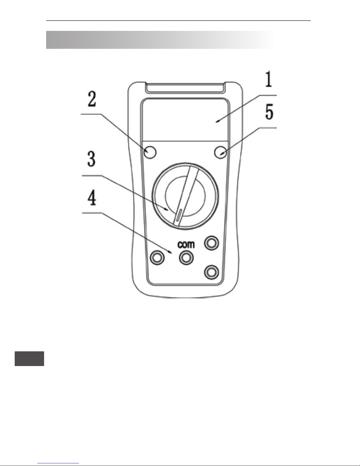
THE METER STRUCTURE
1. LCD display
2. Power button
3. Rotary switch
4. Input terminals
5. Hold button
Diagram 1
7
Owner’s manual
EN
MEASUREMENT OPERATION
First check on 9V battery, then turn rotary switch to the measuring position. lf the low battery,
sign will be displayed on LCD
panel. Nearly to
sign on the meter front panel terminal input
which alarm not exceed the testing voltage and current input value
limitation.
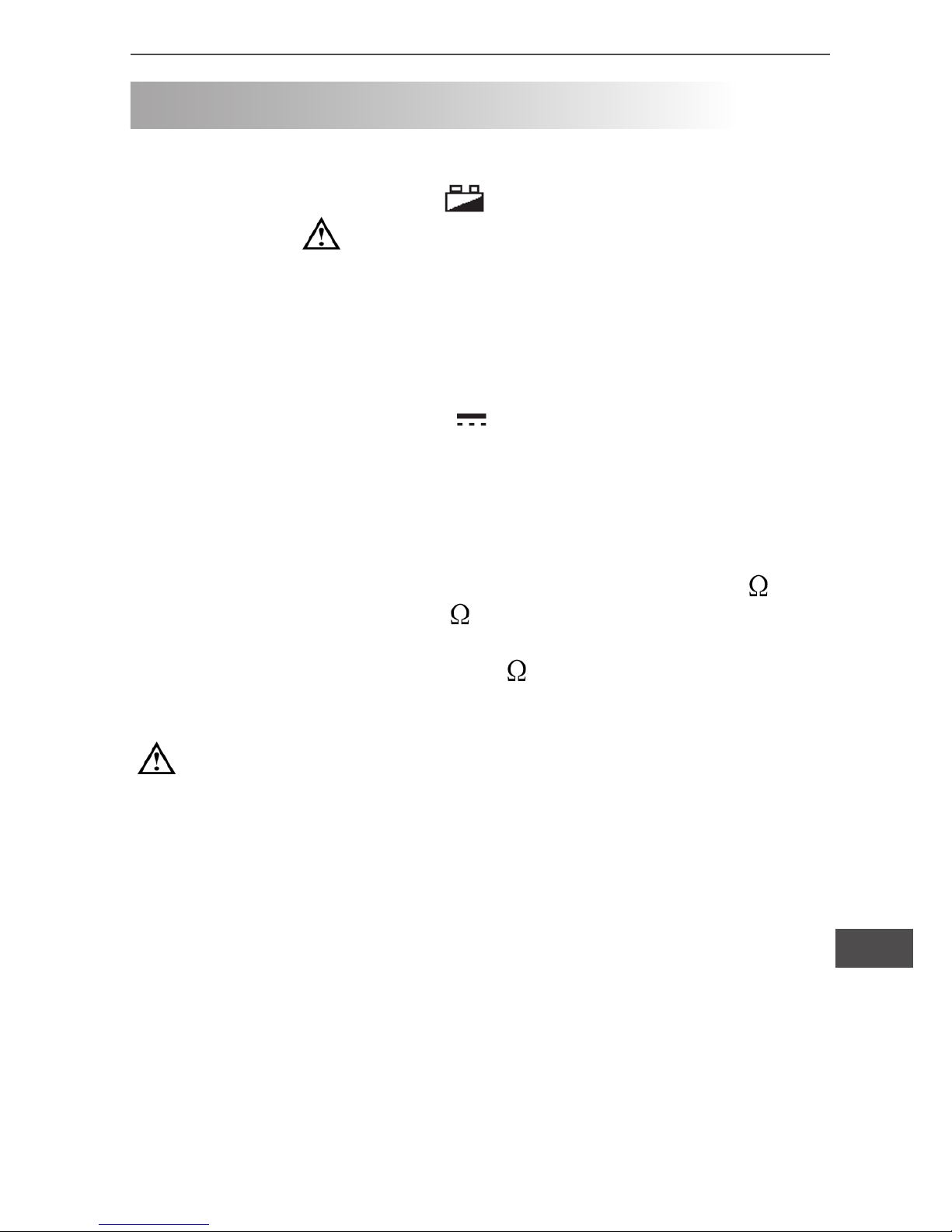
I. DC or AC voltage measurement (see diagram 2)
1) Turn rotary switch to V~ or V voltage measurement.
2) Insert the red test lead into the “V” terminal and the black test
lead into the “COM” terminal, connect the lest leads across with the
object being measured. The measured value shows on the display
AC voltage measurement shows on true root mean square value
stability period.
3) In each range, the meter has an input impedance of 10M . V~
input impedance is about 4.5M . This loading effect can cause
measurement errors in high impedance circuits. If the circuit impedance is less than or equal to 10k , the error is negligible (0.1%
or less).
Warning:
• To avoid possibly damages to the meter, please do not attempt to input higher than 600V.
• To avoid electrical shock, please pay attention during the
high voltage measurement.
Owner’s manual
8
EN
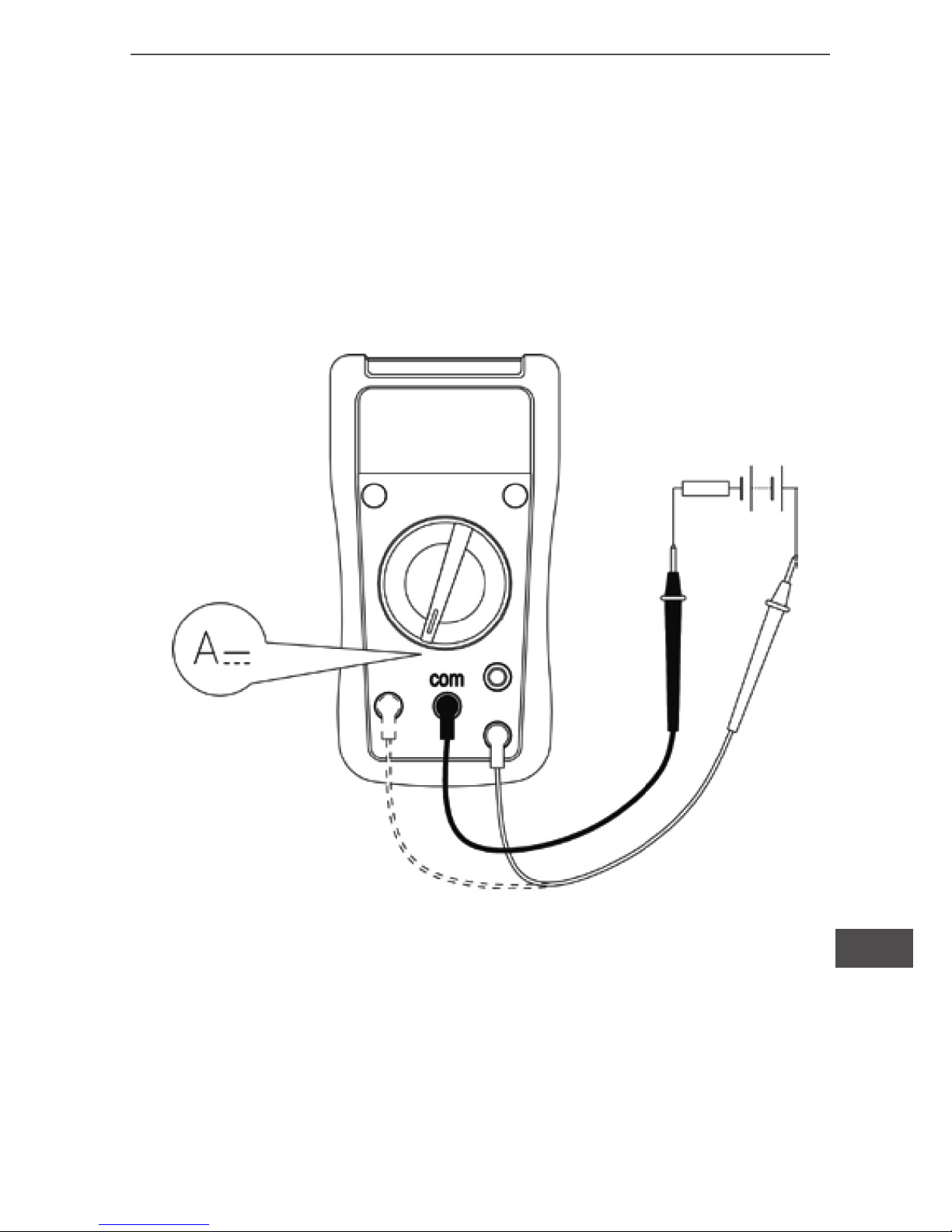
II. DC current measurement (see diagram 3)
1) Turn rotary switch to A current measurement.
2) Insert the red test lead into the „ mA” or ”10A” terminal, and the
black test lead into the „COM” terminal, Connect the test leads
across with the object being measured. The measured value
shows on the display.
Warning:
• Pre-requisites: Turn off power to the circuit before the connection between the test leads across with the object being
measured.
• Selecting the correct terminal input and turn the rotary
switch to select the measuring function. In case of no any idea
on the value input of the current, just simply test from the high
value to low one.
Diagram 2
9
Owner’s manual
EN
• Fuses are located on mA and 10A terminal input.
Never attempt the test lead connect to any circuits especially
on the power supply terminal and may be hurt.
• For the safety purpose, less than 10 seconds is for each
measurement duration and keep 15 minutes duration for next
measurement during the current measurement over 5A.
Diagram 3
Owner’s manual
10
EN
Warning:
• The LCD displays „1” indicating open-circuit for the tested
resistor or the resistor value is higher than the maximum
range of the meter.
• To maintain the resistance measurement accuracy, discount
circuit power and discharge all the high voltage capacitors
during the measuring resistance.
• For high-resistance measurement greater than 1M , it is
normal to take several seconds to obtain a stable reading with
short test leads for measurement.
• Do not input higher than DC 60V and AC 30V voltage to prevent any damage and accident.
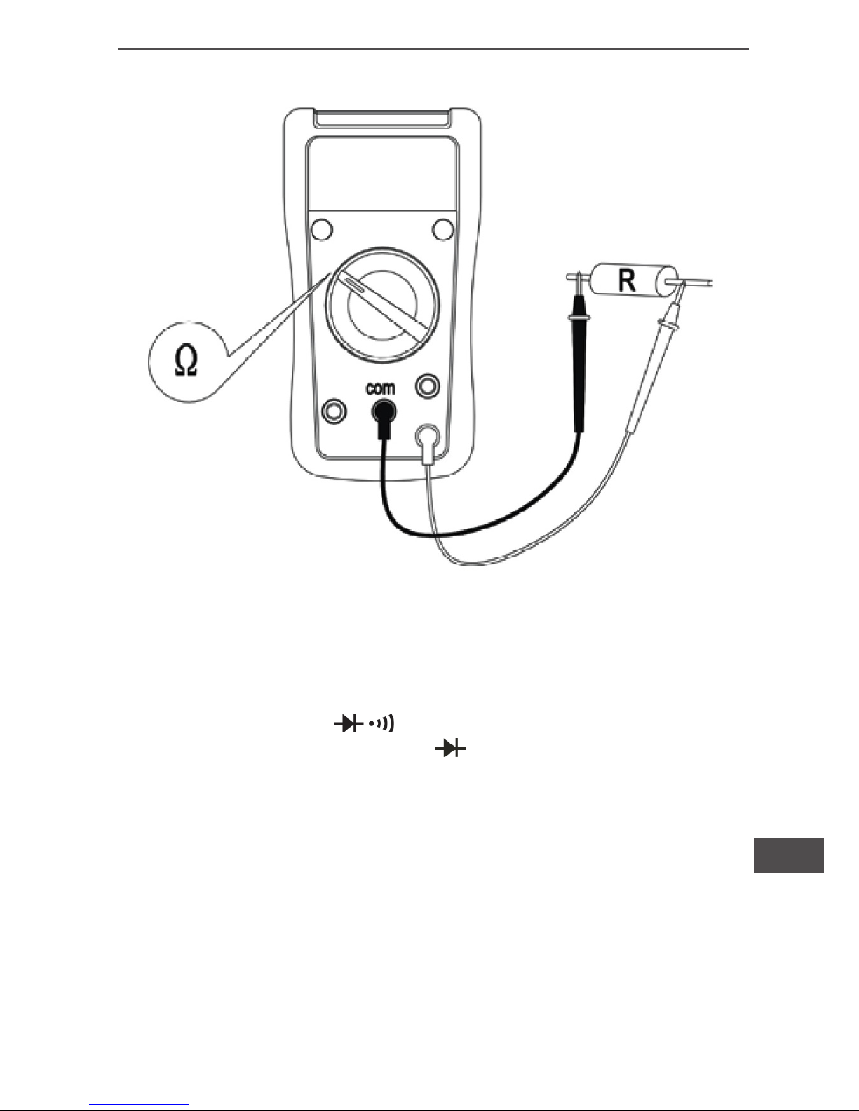
III. Resistance measurement (see diagram 4)
1)Turn rotary switch to “ ” ohm measurement.
2) Insert the red test lead into the “ ” terminal and the black test
lead into the “COM” terminal. Connect the test leads across with
the object being measured. The measured value shows on the
display.
11
Owner’s manual
EN
Diagram 4
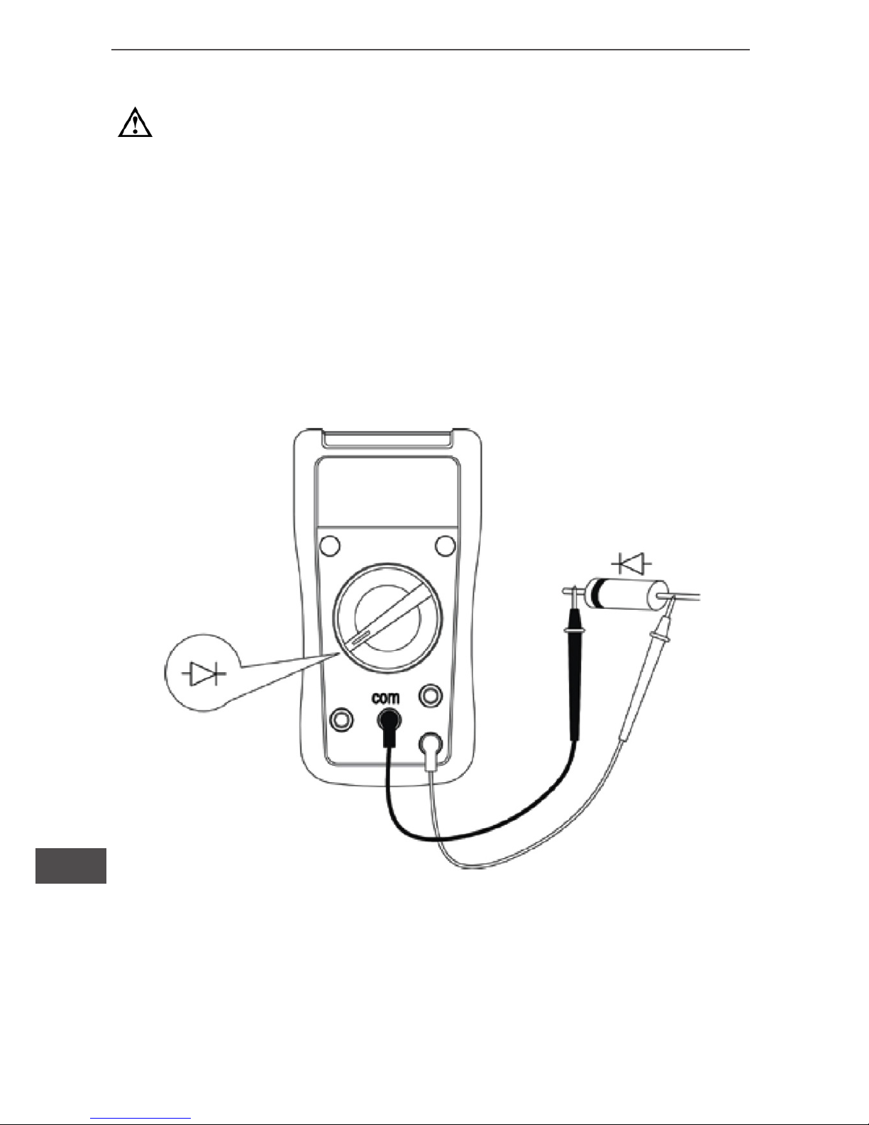
IV. Diodes measurement (see diagram 5)
1)Turn rotary switch to .
2) Insert the red test lead into the
terminal and the black test
lead into the “COM” terminal. Red test lead is “+” Black test lead is
“-”.
3) In a circuit, a good diode should still produce a forward voltage
drop reading of 500~800mV. However, the reverse voltage drop
reading can vary depending on the resistance of other pathways
between the probe tips.
Owner’s manual
12
EN
Warning:
• The LCD displays “1” indicating open-circuit for the tested
diodes or the testing the diodes with polarity.
• To maintain the diodes measurement accuracy disconnect
circuit power and discharge all the high voltage capacitors
during the measuring resistance.
• Do not input higher than DC 60V and AC 30V voltage to prevent any damage and accident.
Diagram 5
13
Owner’s manual
EN
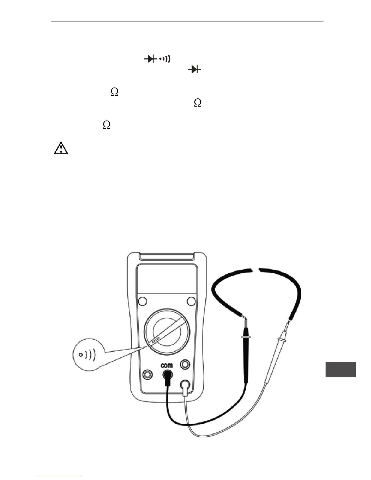
V. Continuity measurement (see diagram 6)
1)Turn rotary switch to .
2) Insert the red test lead into the terminal and the black test
lead into the “COM” terminal. If between both terminals show
resistance >70 , it is a short-circuit,no buzzer, but if between
both terminals show resistances 10 , it is a good connection with
continually buzzer. Resistance value on tested circuit display on
LCD (Unit is
).
Warning:
• To maintain the diodes measurement accuracy disconnect
circuit power and discharge all the high voltage capacitors
during the measuring resistance.
• Do not input higher than DC 60V and AC 30V voltage to prevent any damage and accident.
Diagram 6
 Loading...