

Page 1

LCR Meter LCR-1000 series
Operation Manual V1.0
BENCHTOP
LCR METER
Page 2

I
CONTENTS
SAFETY INSTRUCTION ........................................................................................................................... III
1. PRODUCT INTRODUCTION ............................................................................................................. - 1 -
1-1. Description ................................................................................................................................. - 1 -
1-2. Features ..................................................................................................................................... - 1 -
1-3. Front Panel Introduction ............................................................................................................. - 1 -
1-4. Rear Panel Introduction ............................................................................................................. - 4 -
2. PANEL OPERATION .......................................................................................................................... - 5 -
2-1. <MEAS DISPLAY> ..................................................................................................................... - 5 -
2-2. <BIN DISPLAY> (not available for LCR-1010) .......................................................................... - 9 -
2-3. <MEAS SETUP> ...................................................................................................................... - 10 -
2-4. <SYSTEMS SETUP> ............................................................................................................... - 10 -
2-5. <COMM SETUP> ..................................................................................................................... - 11 -
2-6. <ABOUT SYSTEM> ................................................................................................................. - 11 -
2-8. Data Storage ............................................................................................................................ - 12 -
2-8. <INTER Files List> and <EXT Files List> ................................................................................ - 12 -
3. SPECIFICATIONS ............................................................................................................................ - 15 -
3-1. Measurement Range ................................................................................................................ - 15 -
3-2. Accuracy ................................................................................................................................... - 15 -
4. HANDLER INTERFACE ................................................................................................................... - 19 -
4-1. Pin Definition ............................................................................................................................ - 19 -
4-2. Time Sequence of Interface Signal .......................................................................................... - 20 -
4-4. Schematic Diagram of Interface Signal ................................................................................... - 21 -
5. MAINTENANCE ............................................................................................................................... - 25 -
5-1. Inspection ................................................................................................................................. - 25 -
5-2. Fuse Replacement ................................................................................................................... - 25 -
6. TECHNICAL SPECIFICATIONS ...................................................................................................... - 26 -
Page 3

II
Use of Operation Manual
Please read through and understand this Operation Manual before operating the product. After reading, always
keep the manual nearby so that you may refer to it as needed. When moving the product to another location,
be sure to bring the manual as well.
Calibration Notification
We notify that the LCR meters included in this manual are in compliance with the features and specifications
as stated in this manual. Before shipment, the LCR meter has been calibrated in factory. The calibration
procedures and standards are compliant to the national regulations and standards for electronic calibration.
Warranty
We guarantee that the LCR meter has been passed strict quality check. We warrant our LCR meter’s
mainframe and accessories in materials within the warranty period of one year. We guarantee the free spare
parts for products which are approved defective in this period. To get repair service, please contact with your
nearest sales and service office. We do not provide any other warranty items except the one being provided
by this summary and the warranty statement. The warranty items include but not being subjected to the hinted
guarantee items related to tradable characteristics and any particular purpose. We will not take any
responsibility in cases regarding to indirect, particular and ensuing damage, such as modifications to the circuit
and functions by the users, repairing or component replacement by the users, or damage during transportation.
For product improvement, the specifications are subject to change without prior notice.
Page 4
III
SAFETY INSTRUCTION
This chapter contains important safety instructions that you must follow when operating the LCR meter and
when keeping it in storage. Read the following before any operation to insure your safety and to keep the best
condition for the LCR meter.
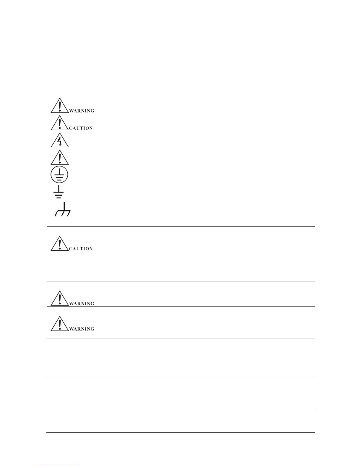
Safety Symbols
The following safety symbols may appear in this manual or on the LCR meter:
WARNING
Identifies conditions or practices that could result in injury or loss of life.
CAUTION
Identifies conditions or practices that could result in damage to the LCR
meter or to other properties.
DANGER
High voltage
ATTENTION
Refer to the manual
Protective conductor terminal
Earth (ground) terminal
Chassis ground terminal
Safety Guidelines
General Instruction
Do not place heavy objects on the casing.
Avoid serious impact or improper handling to prevent damage to the LCR meter.
Preventive measures for releasing static electricity should be taken when
connecting the LCR meter.
Do not block the air ventilation holes on the two sides and on the back of the
chassis.
Do not disassemble the LCR meter unless you are professionals.
Power supply
AC Input voltage: 110V/220V±10%, 50/60Hz
Connect the protective grounding conductor of the AC power cord to an earth ground
to avoid electrical shock.
Fuse
Make sure the correct type of fuse is installed before power up.
Replace the AC fuse with the same type and rating as the original fuse.
Disconnect the power cord before fuse replacement. Make sure the cause of fuse
blowout is fixed before fuse replacement.
Cleaning
Disconnect the power cord before cleaning.
Use a soft cloth dampened in a solution of mild detergent and water. Do not spray
any liquid.
Do not use chemicals or cleaner containing harsh material such as benzene,
toluene, xylene, and acetone.
Operation
environment
Location: indoor, no direct sunlight, dust free, almost non-conductive pollution.
Relative humidity: <80%
Altitude: <2000m
Temperature: 0℃ ~ 40℃
Storage
environment
Location: indoor
Relative humidity: <70%
Temperature: 10℃ ~ 70℃
Page 5
1. PRODUCT INTRODUCTION
1-1. Description
The LCR-1000 series are high precision LCR meter with basic accuracy 0.1% and maximum measurement
frequency 10kHz, 100kHz and 200kHz. The 5-digit 4.3-inch TFT LCD display gives easy reading. The RS-232
interface facilitates in remote control and analysis of measurement results. With its fast measurement speed,
wide frequency range and low cost, the LCR7000 series are widely used in R&D, IQC, online quality control
and automatic test system.
1-2. Features
32-bit core processor
5-digit 4.3-inch TFT LCD display
2 signal source output impedance: 30Ω, 100Ω
100 sets memories for internal storage/save
500 memories for U disk storage/save, supports FAT16 and FAT32 files
Save the last parameter settings before power off
Standard interface: RS-232, HANDLER, USB HOST
Optional interface: USB DEVICE, GPIB
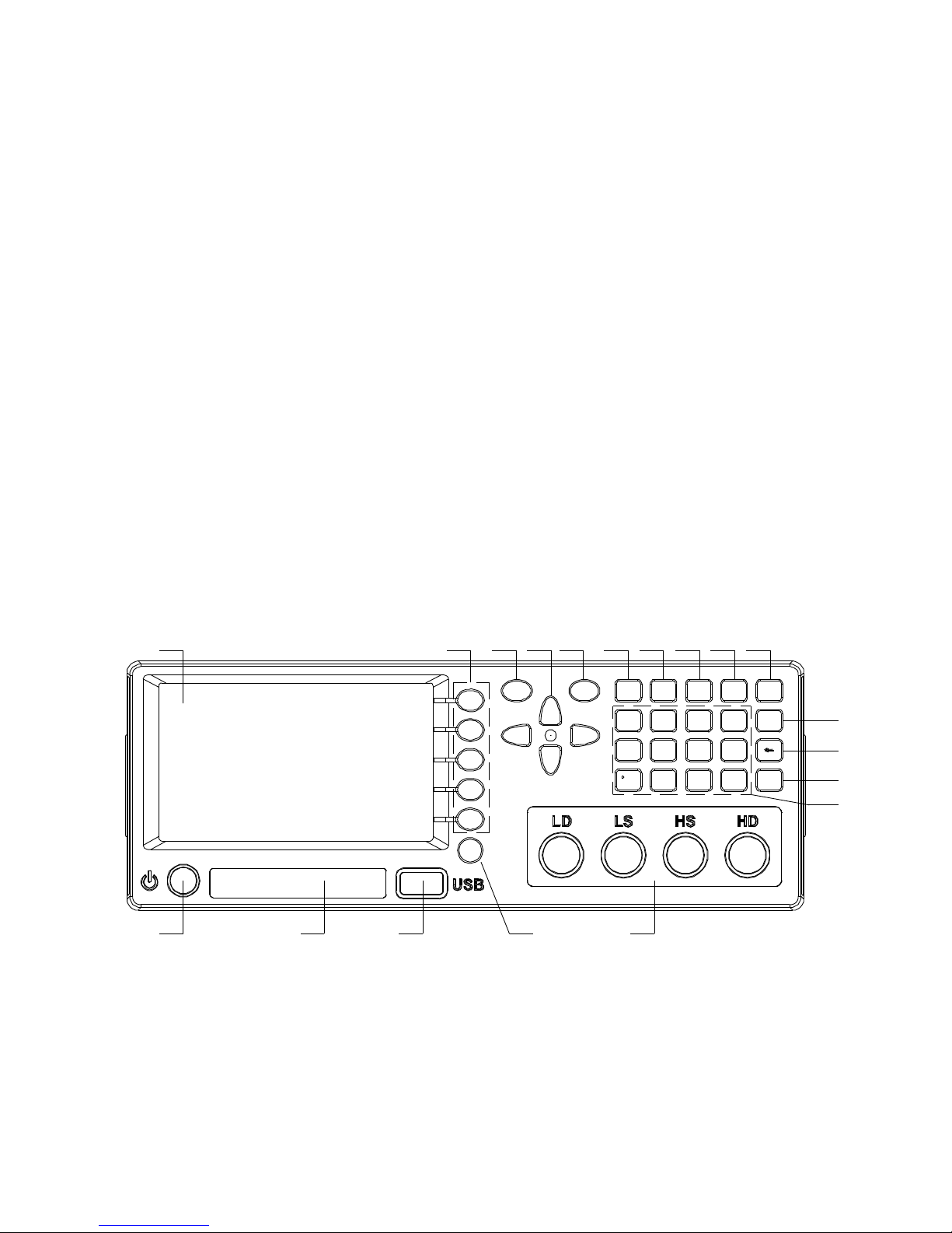
1-3. Front Panel Introduction
PASS FAI L
MEAS SETUP SYSTEM FILE TRI G
4
GHI
10
5
JKL
6
MNO
2
ABC
3
DEF
7
PQRS
8
TUV
9
WXYZ
+/-
ESC
OK
TOOL
1 2 3 54
6 7 9 8 10 11 12 13 14 15
16
17
18
19
1) Power switch
Page 6
Press to power ON or OFF the LCR meter.
2) Name label
It shows brand and model number.
3) USB HOST interface
Connect U flash disk to save or load the file.
4) [TOOL]
Make a short press to this key, the menu soft key area shows corresponding menus. Make a short
press again, the menus disappear.
Make a long press (>1 second) to this key, the LCR meter panel is locked. Other keys (except
TOOL key) are locked, no response to press.
Make a long press again to this key, the LCR meter panel is unlocked. All keys response to press.
When the LCR meter is controlled by RS232, the LCR meter front panel is locked by default. Make
a long press to this key again to unlock the front panel.
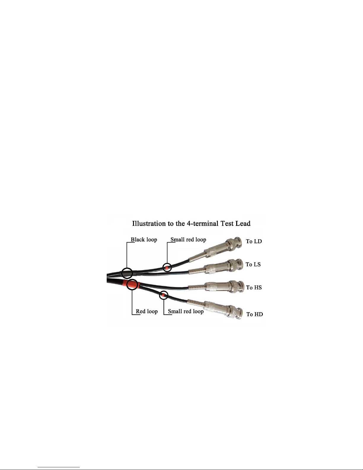
5) Measurement terminals: LD, LS, HS, HD
4-teminal test lead is used to connect 4-terminal test fixture or cable to measure DUT.
It is recommended to use the test lead attached to the LCR meter. Using self-made test lead or test
lead from other suppliers may cause error in measurement results.
6) LCD display
4.3-inch TFT LCD displays measurement results and conditions.
7) Soft keys
Five soft keys are used to select parameters. The corresponding function of each soft key has been
displayed on its left (the right part of LCD). The function definition varies with different pages.
8) CURSOR keys
This key is used to move the cursor on the LCD displayed page. When the cursor moves to a zone,
the corresponding zone will be lightened.
9) PASS indicator
Page 7

The indicator lights on to show that the test result has passed.
10) FAIL indicator
The indicator lights on to show that the test result has failed.
11) [MENU]
Five soft keys are used to select parameters. The corresponding function of each soft key has been
displayed on its left (the right part of LCD). The function definition varies with different pages.
When the LCD display the <MEAS DISPLAY> page and the cursor key moves to <MEAS
DISPLAY>, press [MEAS] key to display the measurement results in full screen.
12) [SETUP]
Press this key to enter measurement parameter setup page.
13) [SYSTEM]
Press this key to Enter system setup page.
14) [FILE]
Press this key to enter file management page.
15) [TRIG]
When the trigger mode is set to MAN mode, press this key to trigger the LCR meter.
16) [ESC]
ESCAPE key.
17) [ ]
BACKSPACE key is used delete the last numeric of the input value.
18) [OK]
This key is used to end the input of data, and confirm and save the data displayed on the inputting
line.
19) Number keys
These keys are used to input data to the LCR meter. The key consists of numerical keys [0] to [9],
decimal point [.] and [+/-] key.
Page 8
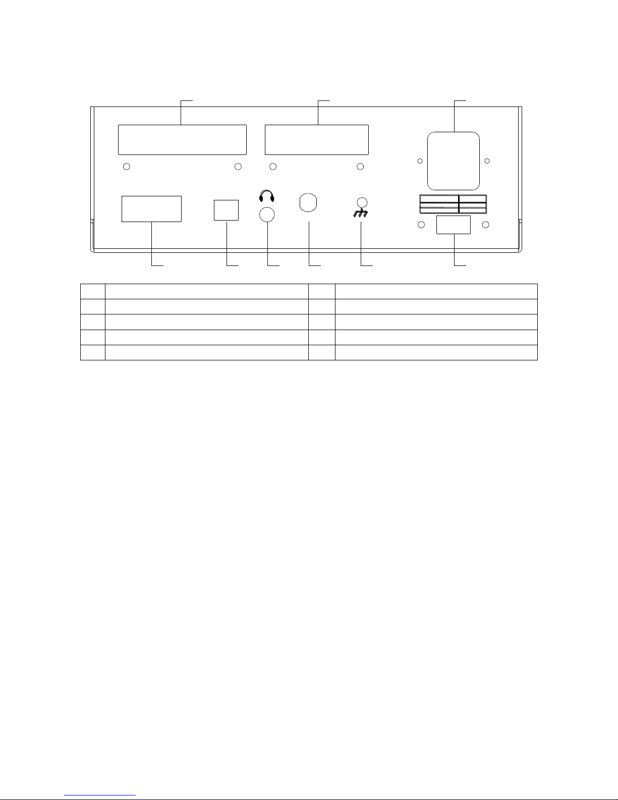
1-4. Rear Panel Introduction
EXT
RS-232C
HANDLER
USB
RATI NG FUSE
¡ «110V/ 60Hz 30VA
¡ «220V/ 50Hz 30VA
T1.0AL 250V
T0.5AL 250V
FOOT. C
1 2 3 4 5 6
789
1
RS-232C interface
6
Voltage selector
2
USB device interface
7
Power socket
3
Headset interface
8
EXT extension interface
4
FOOT.C foot switch interface
9
HANDLER interface
5
GND screw
Page 9
2. PANEL OPERATION
2-1. <MEAS DISPLAY>
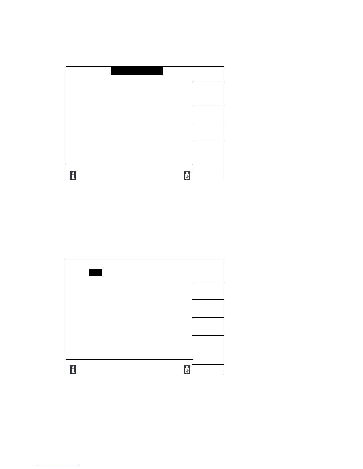
Press [MEAS] key, the <MEAS DISPLAY> page will be displayed on screen as shown below:
< MEAS DISP >
MEAS
FUNC : Cp-D
RANGE : AUTO
DISP
FREQ : 1 kHz
SPEED : SLOW
LEVEL : 1.00V
COMP : OFF
BIN
/
Cp : -0.0015p F
D : 0.3697
DISP
Vm:OFF Im:OFF
QUICK
CLEAR
Use softkeys to select
2-1-1. MEAS DISP
In <MEAS DISP> page, use the four direction keys (▲▼◄►) to move cursor to choose of FUNC, FREQ,
LEVEL, RANGE, SPEED, COMP. Pressing [QUICK CLEAR] softkey can make quick clear to all parameters.
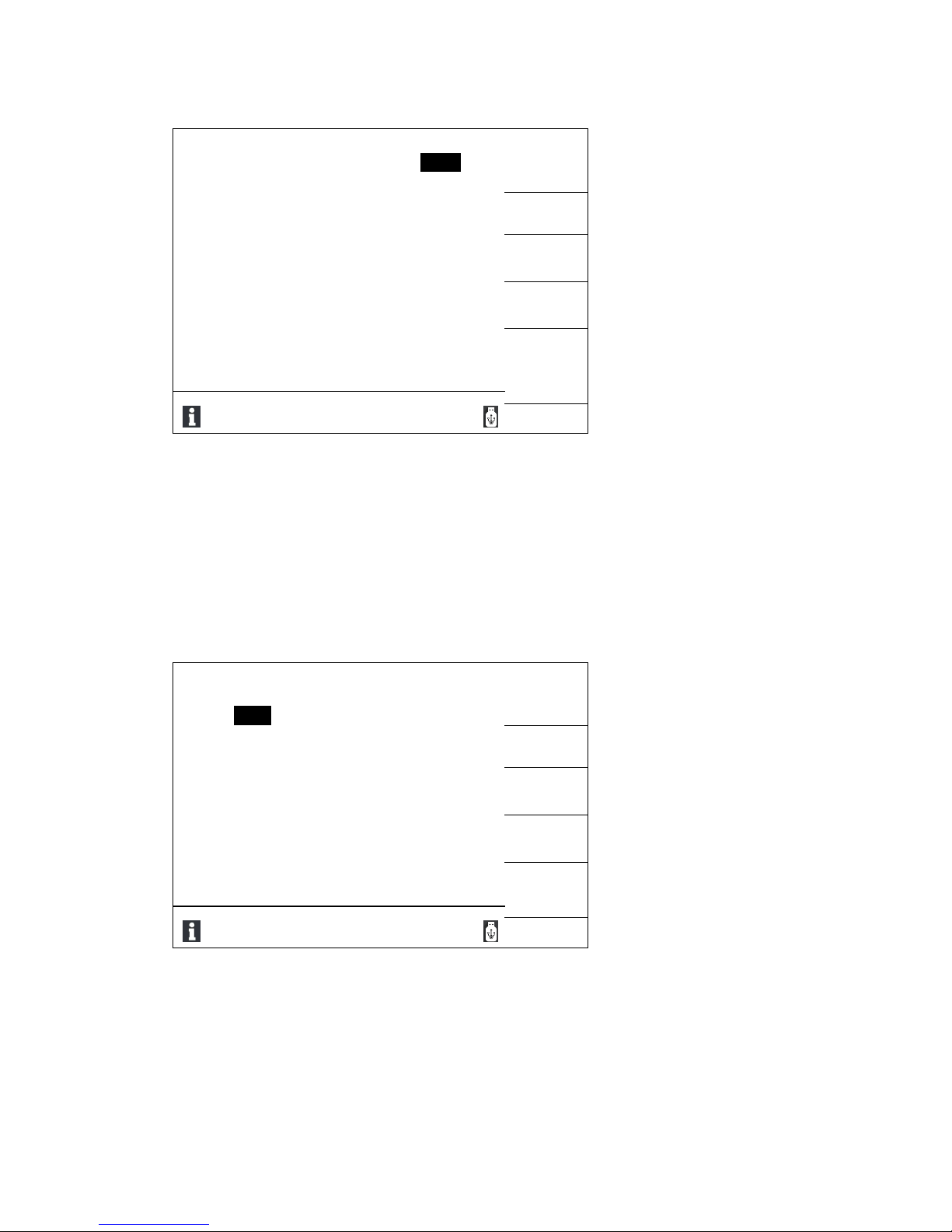
Test parameter
When parameter “Cp-D” of FUNC is selected, other test parameters are display in the right side of the screen.
Each parameter can be selected by its softkey. There are test parameters of Cs-D, Cp-D, Ls-Q, Lp-Q, Rs-Q,
Rs-D, Rp-Q, Rp-D, R-X, Zs-θ, Zs-r.
< MEAS DISP >
Cs-D
FUNC : Cp-D
RANGE : AUTO
FREQ : 1 kHz
SPEED : SLOW
LEVEL : 1.00V
COMP : OFF
Cp-D
/
Cp : -0.0015p F
D : 0.3697
Ls-Q
Lp-Q
Vm:OFF Im:OFF
MORE
1/4
Use softkeys to select
Page 10
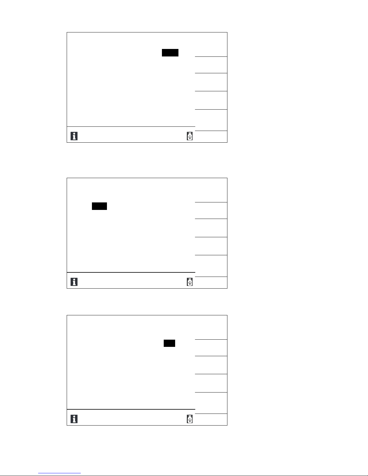
Range mode (not available for LCR-1010)
There are four range modes to choose from: Auto, Hold, Increase +, Decrease -
< MEAS DISP >
AUTO
FUNC : Cp-D
RANGE : AUTO
FREQ : 1 kHz
SPEED : SLOW
LEVEL : 1.00V
COMP : OFF
HOLD
/
Cp : -0.0015p F
D : 0.3697
INCR +
DECR _
Vm:OFF Im:OFF
Use softkeys to select
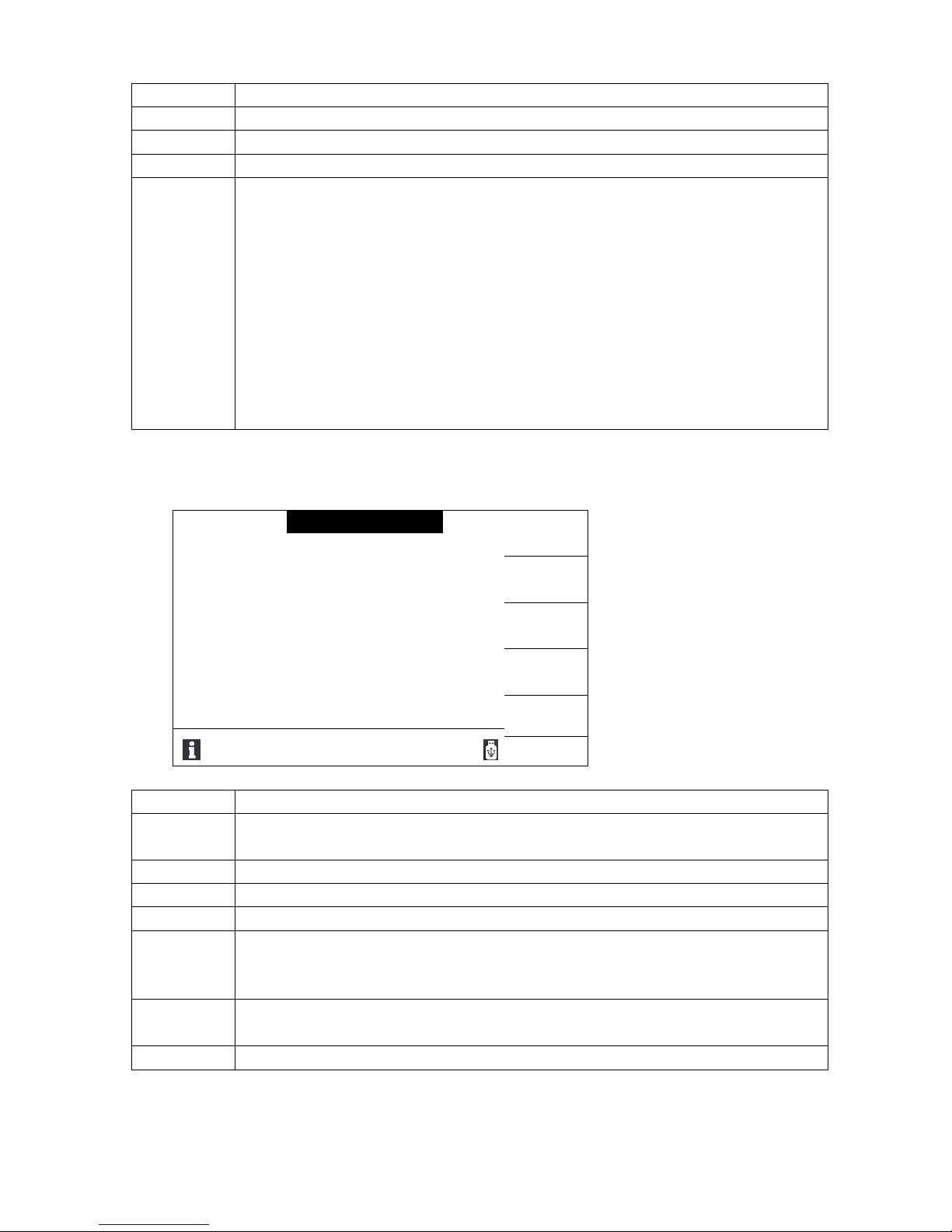
Test frequency
Different models have different test frequency points. Press increase or decrease key to choose the last or the
next frequency points.
LCR-1010: 100Hz,120Hz,1kHz,10kHz
LCR-1030: 100Hz,120Hz,1kHz,10kHz, 20kHz, 30kHz
LCR-1200: 40Hz, 50Hz, 60Hz, 75Hz, 100Hz, 120Hz, 150Hz, 200Hz, 250Hz, 300Hz, 400Hz, 500Hz, 600Hz,
750Hz, 800Hz, 1kHz, 1.5kHz, 2kHz, 2.5kHz, 3kHz, 4kHz, 5kHz, 6kHz, 7.5kHz, 10kHz, 12kHz,
15kHz, 15.7kHz, 16.2kHz, 20kHz, 25kHz, 30kHz, 40kHz, 50kHz, 60kHz, 66.6kHz, 75kHz, 100kHz,
120kHz, 150kHz, 200kHz (38 points)
< MEAS DISP >
INCR + +
FUNC : Cp-D
RANGE : AUTO
FREQ : 1 kHz
SPEED : SLOW
LEVEL : 1.00V
COMP : OFF
INCR +
/
Cp : -0.0015p F
D : 0.3697
INCR +
DECR Vm:OFF Im:OFF
DECR - -
Use softkeys to select
Speed
Speed can be set at fast, medium or slow.
When test frequency ≥1kHz:
Fast: max.30 times/second
Medium: 10 times/second
Slow: 3 times/second
Page 11
< MEAS DISP >
FAST
FUNC : Cp-D
RANGE : AUTO
FREQ : 1 kHz
SPEED : SLOW
LEVEL : 1.00V
COMP : OFF
MED
/
Cp : -0.0015p F
D : 0.3697
SLOW
Vm:OFF Im:OFF
Use softkeys to select
Test level
Test level of LCR-1010 and LCR-1030 can be choose from 0.1V, 0.3V, 1V.
Test level of LCR-1200 can be set from 0.05V to 1V.
< MEAS DISP >
1V
FUNC : Cp-D
RANGE : AUTO
FREQ : 1 kHz
SPEED : SLOW
LEVEL : 1.00V
COMP : OFF
0.3V
/
Cp : -0.0015p F
D : 0.3697
0.1V
INCR +
Vm:OFF Im:OFF
DECR -
Use softkeys to select
Comparator
Comparator can be set ON or OFF. Press <BIN DISP> softkey to enter bin display for more details.
< MEAS DISP >
ON
FUNC : Cp-D
RANGE : AUTO
FREQ : 1 kHz
SPEED : SLOW
LEVEL : 1.00V
COMP : OFF
OFF
/
Cp : -0.0015p F
D : 0.3697
BIN
DISP
Vm:OFF Im:OFF
Use softkeys to select
Page 12

Parameter area
In parameter area, the test parameter and its value are displayed.
Font size of the parameters can be set as small size of large size by pressing [FONT] softkey.
Parameter value display can be turn on or off by pressing [DISP] softkey.
Deviation can be set as OFF, ABS or % by pressing [DEV] softkey.
< MEAS DISP >
FONT
SMALL
FUNC : Cp-D
RANGE : AUTO
FREQ : 1 kHz
SPEED : SLOW
LEVEL : 1.00V
COMP : OFF
DISP
OFF
/
Cp : -0.0015p F
D : 0.3697
DEV
OFF
Vm:OFF Im:OFF
Use softkeys to select
Page 13

Monitored Voltage and Current
Vm and Im are monitored voltage and current of the DUT respectively. When Vm or Im is selected, it can be
set ON or OFF.
< MEAS DISP >
ON
FUNC : Cp-D
RANGE : AUTO
FREQ : 1 kHz
SPEED : SLOW
LEVEL : 1.00V
COMP : OFF
OFF
/
Cp : -0.0015p F
D : 0.3697
Vm:OFF Im:OFF
Use softkeys to select
2-2. <BIN DISPLAY> (not available for LCR-1010)
Press [BIN DISP] key in the pay of <MEAS DISP>, the <BIN DISPLAY> page will be displayed on screen as
shown below:
< BIN DISP >
MEAS
COMP : OFF
AUX : OFF
COUNT : OFF
SETUP
NOMINAL: 0.0000pF
MODE : ABS
BIN
LOW [ ]
HIGH [ ]
COUNT
1 2 3 2nd AUX : OFF
OUT :
BIN
DISP
\
Cp: -0.0009p F
BIN:
D : 0.0033
QUICK
CLEAR
Use softkeys to select
COMP: Set comparator ON or OFF
AUX: Set auxiliary ON or OFF
COUNT: Set counting ON or OFF
NOMINAL: Input nominal value via numeric keys or softkeys. It is reference value of main parameter range.
Deviation is for main parameters only. There are 3 operations to Deviation: OFF, ABS or %.
ABS (Absolute Deviation): The absolute deviation is the currently measured value minus preset nominal
value. Its calculation formula is: ⊿ABS = X – Y.
X is the currently measured value. Y is preset nominal value.
% (percentage deviation): The percentage deviation is the percentage of the difference between the
currently measured value and the preset nominal value. Its calculation formula is: ⊿% = (X – Y)/
Y×100[%]
X is the currently measured value. Y is preset nominal value.
Page 14

2-3. <MEAS SETUP>
Press [SETUP] key, <MEAS SETUP> page will be displayed on screen as shown below:
< MEAS SETUP >
MEAS
SETUP
ResSource
:
30Ω
AVERAGE
: 1
RangeDwe I I
:
0 ms
TrigSource
:
INT TrigDelay
:
0 ms
TrigEdge
:
RISING
Handler
:
CLEAR
PulseWidth
:
1 ms
Use softkeys to select
ResSource
Set internal resistance source at 30Ω or 100Ω
AVERAGE
Set average number of times between numbers 1 to 255. Input numbers by numeric keys
or soft key “+” and “-”.
RangeDwe I I
Set range delay time between 0ms to 6000ms. Input numbers by numeric keys or soft key
“+” and “-”.
TrigSource
Set trigger source as INT or EXT.
TrigDelay
Set trigger display time between 0ms to 6000ms. Input numbers by numeric keys or soft
key “+” and “-”.
TrigEdge
Set trigger edge as RISING or FALLING.
Handler
Set comparator to CLEAR, HOLD, PULSE.
PulseWidth
Set pulse width between 1ms to 9999ms.
2-4. <SYSTEMS SETUP>
Press [SYSTEM] key, <SYSTEMS SETUP> page will be displayed on screen as shown below:
< SYSTEM SETUP >
SYSTEM
Theme
TRAD-BLUE
SETUP
Language
:
英语
COMM
Key Tone
:
ON SETUP
ToneSour
:
MASTER
ABOUT
PassTone
:
OFF
SYSTEM
FailTone
:
TWO SHORT
SYSTEM
ParaSave
:
AUTO SAVE
DEBUG
PassWord
:
OFF
Use softkeys to select
Theme
Set display theme to BLUE, BLACK or GREEN.
Language
Set language as English or Chinese
Key Tone
Turn on or off key tone.
Page 15
ToneSour
Set tone source as MASTER, EAR PHONE or ALL.
PassTone
Set pass tone OFF, or set pass tone as LONG tune, SHORT tune, TWO SHORT tunes.
FailTone
Set fail tone OFF, or set fail tone as LONG tune, SHORT tune, TWO SHORT tunes.
ParaSave
Set parameter save mode as AUTO SAVE, AUTO LOAD, or NO SAVE.
PassWord
In this page, press corresponding softkeys to choose different functions:
1) Set password OFF
2) Lock system: when setting password to lock system, all files are protected and
password is required during power on
3) Lock file: it means protecting files.
4) Modify password: the default password is 0010 for LCR-1010, 0030 for LCR-1030 and
0200 for LCR-1200.
5) Save to USB flash disk: The password can be save to USB flash disk. The password
file name is “0010.STA” for LCR-1010, “0030.STA” for LCR-1030, “0200.STA” for LCR-
1200. Plug USB flash disk into USB HOST, when a password is required during power
on, the LCR meter automatically detects the password file and read it to get password.
2-5. <COMM SETUP>
Press [COMM SETUP] softkey, <COMM SETUP> page will be displayed on screen as shown below:
< COMM SETUP >
SYSTEM
Bus Mode
:
RS232C
SETUP
BaudRate
:
9600
COMM
Data Bit
: 8
SETUP
Stop Bit
: 1
ABOUT
Parity
:
None
SYSTEM
Tx Term
:
LF GpibAddr
:
08 CMD Type
:
SCPI
Use softkeys to select
Bus Mode
Set bus mode as RS232C, GPIB, USBTMC or USBCDC.
BaudRate
Use “+” or “-” to choose baud rate from 4800, 9600, 19200, 38400, 115200.
Baud rate is only for bus mode RS232C.
Data Bit
Set data bit as 6, 7 or 8.
Stop Bit
Set stop bit as 1 or 2.
Parity
Set parity as NONE, ODD, or EVEN.
Tx Term
Set end of text term as LF, CR or LFCR.
In response to ASCII code, LF is 0x0A and CR is 0x0D.
This is only end of text term when the LCR meter is returning data to PC.
GpibAddr
Set GPIB address between 0 to 31. Input numbers via numeric keys or softkeys.
This is only for bus mode GPIB.
CMD Type
Please refer details to Programming Manual.
2-6. <ABOUT SYSTEM>
Press [ABOUT SYSTEM] softkey, the <ABOUT> page will be displayed on screen as shown below:
Page 16

< ABOUT >
Reset
Factory
Model number:
: Serial number
:
GL-817-02333
Firmware version
:
1.8.1
Hardware version
:
1.0.1
Update
License
:
Registered
EXIT
Use softkeys to select
Reset
Press the softkey to restart the LCR meter.
Factory
Press the softkey to return to factory setup. Password is required.
Update
Press the softkey to update firmware through USB flash disk.
EXIT
Press the softkey to exit and return to <SYSTEM SETUP> page.
2-8. Data Storage
The measurement data can be stored to USB flash stick. In <MEAS> page, press [TOOL] key to enter into
data storage menu.
< MEAS DISP >
PrtSc
FUNC : Cp-D
RANGE : AUTO
FREQ : 1 kHz
SPEED : SLOW
LEVEL : 1.00V
COMP : OFF
SAVE
DATA
/
Cp : -0.0015p F
D : 0.3697
SINGLE
SHORT
SINGLE
OPEN
Vm:OFF Im:OFF
Use softkeys to select
There are three formats for data storage: <A>,<B> [,<COMP>]
A and B are measurement results for main parameter and secondary parameter respectively. The
measurement results are stored in the way of scientific notation.
<COMP> is comparator results. LCR-7010 dose not have handler function.
COMP
Description
COMP
Description
0
Fail
3
BIN 3pass
1
BIN 1 pass
4
AUX fail
2
BIN 2 pass
5
No comparator
2-8. <INTER Files List> and <EXT Files List>
The parameter settings can be saved into the internal non-volatile memory. When same parameter settings
Page 17

are needed in the next measurement, user can easily upload parameter settings from the internal non-volatile
memory. No need to make settings again.
Press [File] key, the <Files List> page will be displayed. Press [File] key again to switch between internal and
external files lists.
< INTER Files List >
LOAD
I:\
Page: 1
NO File
STORE
1
2
DEL
3 4
FIND
5 6
COPY TO
E:
7
Use softkeys to select
< EXT Files List >
LOAD
I:\
Page: 1
File/Folder
STORE
DEL
PARENT
DIR
COPY TO
I:
Press / to page, FILE to change I/E !
Use softkeys to select
Operation steps:
1. Read existing files
1) Use ▲ and ▼ keys to choose files. Or Input numbers to choose corresponding file, and then press
[OK] key to confirm.
2) Use ◄ and ► keys o choose pages.
2. Save parameter to files
1) Move cursor to file number. Press [STORE] softkey to save parameter to the selected file.
2) Press [YES] softkey to continue, or press [NO] softkey to cancel operation.
3) If press [YES] softkey in step 2, input file name via numeric keys and then press [OK] to confirm. If the
file name already exists, press [Continue] softkey to cover the existing file of press [ESC] to cancel
operation.
3. Upload parameters from existing files
1) Press [File] key to switch to internal or external files list.
Page 18

2) Move cursor to the file name to be uploaded from, or input file name directly.
3) Press [LOAD] softkey.
4) Press [YES] softkey to upload file.
4. Copy file to USB flash disk
1) Plug USB flash disk into USB host.
2) Move cursor to the file name to be copied, or input file name directly.
3) Press [YES] softkey to copy.
4) If the file name already exists, press [Continue] softkey to cover the existing file of press [ESC] to
cancel operation.
Page 19

3. SPECIFICATIONS
3-1. Measurement Range
With 100Ω source resistance, there are five ranges: 31.6Ω, 100Ω, 1kΩ, 10kΩ, 100kΩ.
With 30Ω source resistance, there are six ranges: 10Ω, 30Ω, 100Ω, 1kΩ, 10kΩ, 100kΩ.
The effective measurement range is listed as below.
Table 3-1 Effective measurement range
with 100Ω source resistance
Table 3-2 Effective measurement range
with 30Ω source resistance
No.
Resistance
Effective mea.range
No.
Resistance
Effective mea.range
0
100kΩ
100kΩ-100MΩ
0 100 kΩ
100kΩ-100MΩ
1
10kΩ
10kΩ-100kΩ
1 10 kΩ
10kΩ-100kΩ
2
1kΩ
1kΩ-10kΩ
2 1 kΩ
1kΩ-10kΩ
3
100Ω
50Ω-1kΩ
3 100Ω
100Ω-1kΩ
4
30Ω
0Ω-50Ω
4 30Ω
15Ω-100Ω
5 10Ω
0Ω-15Ω
3-2. Accuracy
3-2-1. Accuracy of │Z│, L, C,R, X
The accuracy (A
e
) of │Z│,L,C,R,X is shown as below:
Ae= ±[A+(Ka+Kb+Kf)×100+KL]×K
c
[%]
A: Basic measurement accuracy (Refer to Fig.3-1)
K
a
:Impedance scaling factor (Refer to table 3-4), impedance <500Ω
K
b
:Impedance scaling factor (Refer to table 3-4), impedance >500Ω
K
c
:Temperature factor (Refer to table 3-5)
K
f
:Calibration interpolation factor (Refer to table 4-6)
K
L
:Cable length factor (Refer to table 4-7)
Note: Choose only Ka or Kb, depending on resistance value. For others, input zero.
Condition for L, C, X accuracy: D
x
(D measured value)≤0.1
Condition fo R accuracy: Q
x
(Q measured value)≤0.1
When Dx≥0.1, for L, C and X, its accuracy factor Ae shall be multiplied by
2
1xD
When Qx≥0.1, for R, its accuracy factor Ae shall be multiplied by
2
1xQ
Page 20

3-2-2. Accuracy of D
The accuracy De of D is calculated according to: De=
100
eA
The above formula is valid only when D
x
≤0.1.
When Dx>0.1, De shall be multiplied by (1+D
x
).
3-2-3. Accuracy of Q
The accuracy Qe of Q is calculated according to: Qe =
ex
ex
DQ
DQ
1
Here Qx is the measured value of Q. D
e
is the accuracy of D.
The above formula is valid only when Qx×D
e
<1.
3-2-3. Accuracy of θ
The accuracyθe of θ is calculated according to: θe =
100
180 eA
[deg]
3-2-4. Accuracy of Rp
When Dx (the measured value of D) ≤0.1 The accuracy of R
p
is calculated according to:
Rp =
ex
epx
DD
DR
[]
Here, R
px
is the measured value [] of R
p
. Dx is the measured value of D. D
e
is the accuracy of D.
3-2-5. Accuracy of Rs
When Dx (the measured value of D) ≤0.1 The accuracy of R
s
is calculated according to:
Rse = Xx×D
e
[]
Xx = 2πfLx=
xfC
2
1
Here, Xx is the measured value [S] of X. Cx是is the measured value [F] of C. Lx is the measured value [H] of L.
D
e
is the accuracy of D. f is measured frequency.
Page 21

Basic measurement accuracy (Fig.3-1)
In Fig.3-1, the basic accuracy A can be selected by below method:
0.1 (a smaller value): When VS=1V, measurement speed is accuracy of medium and slow speed.
0.2 (a larger value): When VS=1V, measurement speed is accuracy of fast speed.
Page 22

When measuring level correction level ArB (Refer to table 3-3), select measuring accuracy A according to
Fig.3-1, the basic accuracy after level correction is A multiplied by Ar. Here, V
S
is voltage of test signal.
Table 3-1
Test Signal Voltage
V
S
Accuracy Correction Factor
Ar
0.1V
2.5
0.3V
1.5
1V
1
Table 3-4 Impedance Scaling Factor Ka and K
b
Speed
Frequency
K
a
(Zm<500)
K
b
(Zm>500)
Medium
Slow
fm100Hz
)
100
1)(
200
1)(
101
(
3
msm fVZ
)
100
1)(
70
1)(101(
9
ms
m
fV
Z
100Hzfm
≤100kHz
)
200
1)(
101
(
3
sm VZ
)
70
1)(101(
9
s
m
V
Z
fm100kHz
)
200
2)(
101
(
3
sm VZ
)
70
1)(103(
9
s
m
V
Z
Fast
fm100Hz
)
100
1)(
400
1)(
105.2
(
3
msm fVZ
)
100
1)(
100
1)(102(
9
ms
m
fV
Z
100Hzfm
≤100kHz
)
400
1)(
105.2
(
3
sm VZ
)
100
1)(102(
9
s
m
V
Z
fm100kHz
)
400
2)(
105.2
(
3
sm VZ
)
100
1)(106(
9
s
m
V
Z
Note:
fm: measured frequency, [Hz]
Zm: measured impedance of DUT, []
Vs: voltage of test signal, [mV
rms
]
Table 3-5 Temperature Factor K
c
Temperature (℃)
5 8 18 28 38
K
c
6 4 2 1 2
4
Table 3-6 Calibration Interpolation Factor Kf
Test frequency
Kf
Typical frequency (Direct calibration)
0
Non-typical frequency (Interpolation
calibration)
0.0003
Note: So far frequency points of all models are typical frequencies.
Table 3-7 Cable Length Factor
Test frequency
Cable Length
0m
1m
2m
Page 23

0.1Vrms ,0.3Vrms
0
2.510-4(1+0.05fm)
510-4(1+0.05fm)
1Vrms
0
2.510-3(1+0.016fm)
510-3(1+0.05fm)
Note: fm: measured frequency, [Hz]
4. HANDLER INTERFACE
The HANDLER interface is used to output comparator results to industrial computer (IPC), so as to realize automatic
comparator test.
4-1. Pin Definition
Fig.4-1 Pin definition
Pin No.
Signal
Description
1
2
3
10
11
/P1
/P2
/P3
/NG
/AUX
Comparator result output.
All signals are collector outputs with built-in pull-up resistor. Pul-up power source
can be internal +5V power source or exteran power source EXTV (default at
EXTV).
Resistance of the built-in pull-up resistor is 4.7kΩ.
12,13
/EXT.TRIG
Rising edge of this signal triggers measurement. Pulse width≥1μs. Low level drive
current approx. 5-10mA.
16,17,18
+5V
Internal +5V power output: Normally it is not recommended to use internal power
source. If the internal power source must be used, please make sure the signal’s
current is less than 0.3A and ensure the signal is well shielded from interference.
27,28
EXTV
External DC power source input for comparator signal.
If using internal +5V power source, please reset the internal jumper connection.
30
/IDX
/IDX is valid after A/D conversion is finished.
When the signal is valid, the automatic tester will allow the next component to move
into measuring position. The currently measured result will be output when /EOM
is valid.
31
/EOM
End Of Measurement: the signal is valid when the measured results and comparing
Page 24

results are valid.
34,35,36
COM
Reference ground for external power source EXTV.
When using internal +5V power source for the HANDLER interface signal output,
reference ground of the LCR meter is connected with COM.
4-2. Time Sequence of Interface Signal
Fig.4-3 Time sequence chart
Time
MIN Value
MAX Value
T1: Trigger pulse width
T2: Delay time of starting measurement
T3: Trigger waiting time after /EOT output
1us
200us
0us
Display time + 200us
---
Page 25

4-4. Schematic Diagram of Interface Signal
If using internal +5V power source: connect pin 1 to pin 2 of J205; and connect pin 1 to pin 2 of J204.
If using external EXTV power source: connect pin 2 to pin 3 of J205; and connect pin 2 to pin 3 of J204.
5. REMOTE CONTROL
The LCR meter is available with RS232C interface and USB HOST as standard. GPIB is an optional interface.
5-1. RS232C Interface
The RS232C interface of this LCR meter is not strictly based on international RS232 standards. Only the
minmal subset as table 5-1 is available.
Table 5-1 Fig.5-1 Connection illustration
Signal
Abbreviation
Connector’s Pin number
Send data
TXD
2
Receive data
RXD
3
Ground
GND
5
5-3. Description to GPIB Interface
The GPIB (IEEE488) interface is a universal intelligent instrument bus interface. The LCR meter can be
connected with computer or other intelligent instruments through GPIB interface to construct an automatic test
system with other instruments. Maximum 15 units of instruments can be connected to one bus at the same
time. The LCR meter adopts IEEE488.2 standards. The command system is open. User can control the LCR
meter by sending commands.
TIPS:
Page 26
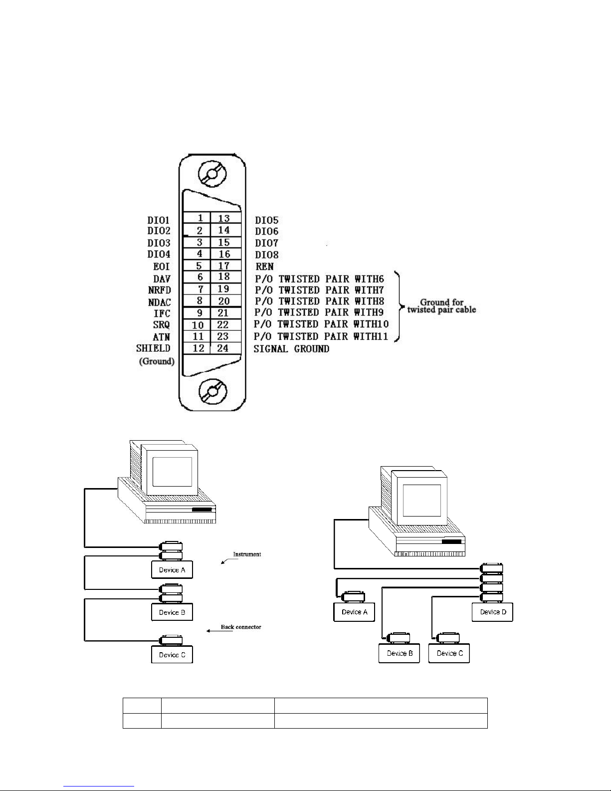
1. In one bus system, the connecting cable of each unit shall be less than 2 meters. Total cable length shall
be less than 20 meters.
2. Maximum 15 units can be connected to one bus.
3. There is no rule on how to connect cables. However, it is recommended to impose four back connectors
on one instrument.
Fig.5-2 GPIB Connector and Pinout
Figt.5-3 Superimposition of two back connectors Figt.5-4 Superimposition of four back connectors
Connector’s function:
Code
Function
Description
SH1
Data source contact
Three line connection
Page 27
AH1
Receiver communication
Three line connection
T5
Speak function
Send instrument information
L4
Listen function
Receive instrument information
SR1
Service request
Demand service
RL1
Remote/local switch
Switch between remote control and local control
DC1
Reset instrument
Send CLEAR signal
DT1
Trigger instrument
Send trigger signal
C0
Control function
Send control signal
5-3-1. GPIB Address
GPIB address can be set between numbers from 0 to 31. Please refer to [SYSTEM] menu for details of
interface setup.
5-3-2. GPIB Bus Function
Commands
Description
AORT I/O (IFC)
Stop all bus actions. Stop receiving instrument’s data. Reset the interface to
idle state.
CLEAR LOCKOUT/
SET LOCAL
Prepare the instrument for remote control.
DEVICE CLEAR
(SDC or DCL)
Clear the selected instrument, or clear all instruments.
LOCAL LOCKOUT (LLO)
Lock local commands. Carry out this command.
REMOTE
Set the instrument to remote control mode.
SPOLL
This is Serial naming command, which is used to configure the bus address
status byte. 8 bytes are used to mask and read to determine the operating
status of the instrument.
SERVICE REQUEST
When the series instrument requests the controller to perform a task, the
instrument will send SRQ (service request) signal. SRQ signal is considered as
an interrupt that tells the controller to be prepared for data transmission or there
is an error condition. When the series instrument sends the SRQ service
request signal, it also sets the status byte to 6 bits. The 6 bits are RQS request
service bits, sometimes as a status bit when concatenated with the naming
command. When the series instrument serializes, it clears the RQS (Request
Service) bit and the SRQ line. Each byte of the status byte initiates an SRQ
service request. The user can mask the status byte to determine which one
caused the series instrument to set the SRQ line. See "Status Bytes" for details.
TRIGGER (GET)
Trigger bus commands. This command can be sent to the selected instrument
or all the instruments as the listener. The series instruments must first be
assigned to the listener and then set the bus trigger mode to trigger mode before
sending the trigger message
5-4. USB HOST
The USB HOST can be used to control the LCR meter It is in compliance with USMTMC-USB488 and USB2.0
Page 28

protocols. When using USBTMC interface, user can write commands via Labview to control the instrument.
In the first time of connecting the instrument to computer via USB cable, the computer will reminds of “Find
New Device” and then pop up installation windows. Follow the installation instructions and install the USB
driver successfully. A “USB Test and Measurement Device” will be found in the Device Manager.
Page 29
6. MAINTENANCE
6-1. Inspection
Inspect the LCR meter at regular intervals so that it maintains its initial performance for a long time.
Check the input power cord for damage of the vinyl cover and overheating of the plug and cord stopper.
Check the terminal screws and binding posts for loosening.
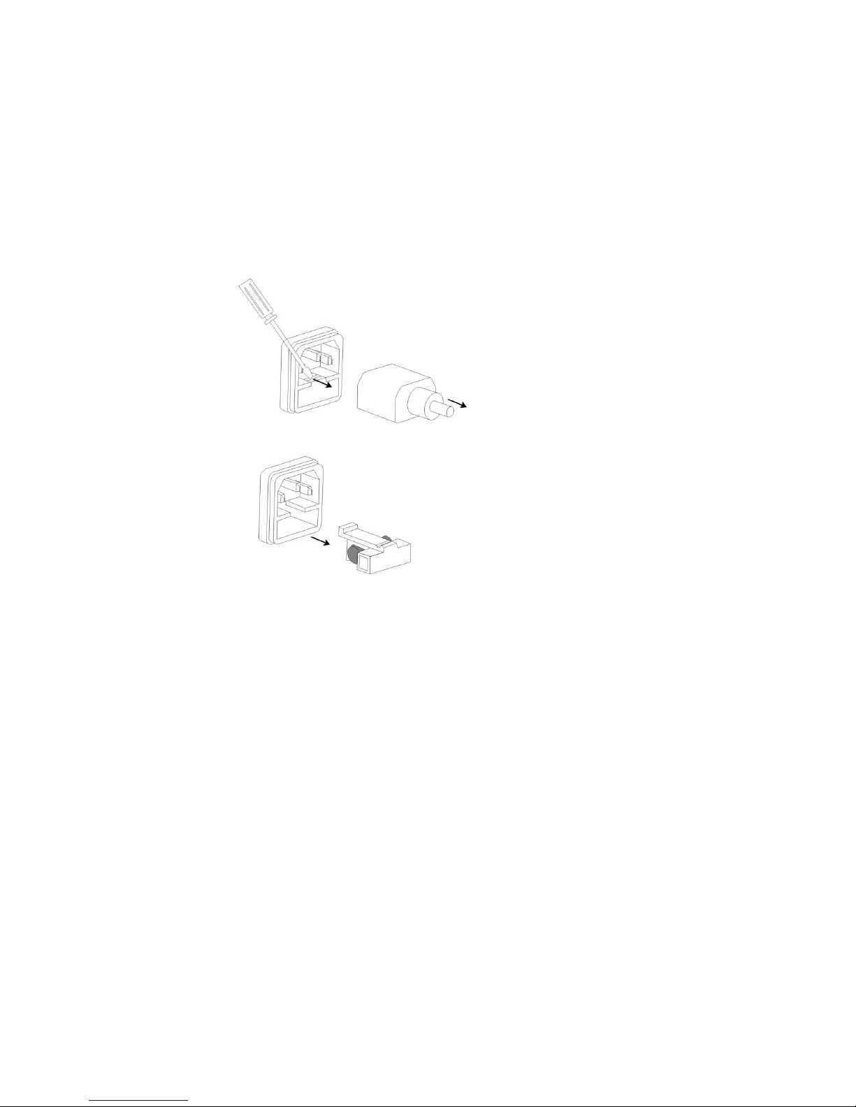
6-2. Fuse Replacement
Step
1) Take off the power cord and remove the fuse socket using a minus driver.
2) Replace the fuse in the holder.
Fuse rating: T1.0/250V for 110Vac input, T0.5/250V for 220Vac input.
Page 30
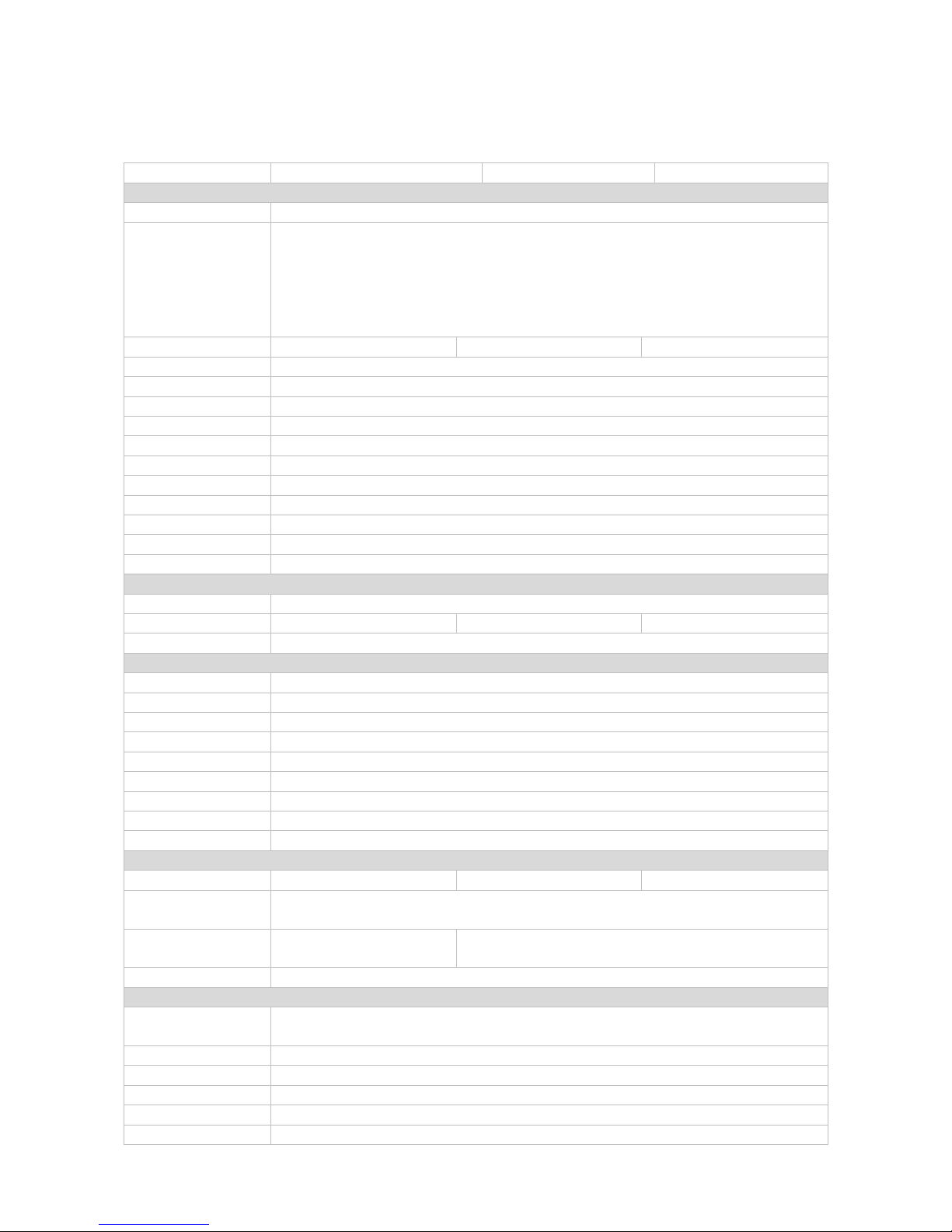
7. TECHNICAL SPECIFICATIONS
The specifications apply when the LCR meter is powered on for at least 30 minutes under regulated
temperature.
Model
LCR-1010
LCR-1030
LCR-1200
Measurement function
Test parameter
| Z|, |Y|, C, L, X, B, R, G, D, Q, θ
Test signal frequency
LCR-1010: 100Hz,120Hz,1kHz,10kHz
LCR-1030: 100Hz,120Hz,1kHz,10kHz, 20kHz, 30kHz
LCR-1200: 40Hz, 50Hz, 60Hz, 75Hz, 100Hz, 120Hz, 150Hz, 200Hz, 250Hz, 300Hz, 400Hz,
500Hz, 600Hz, 750Hz, 800Hz, 1kHz, 1.5kHz, 2kHz, 2.5kHz, 3kHz, 4kHz, 5kHz, 6kHz, 7.5kHz,
10kHz, 12kHz, 15kHz, 15.7kHz, 16.2kHz, 20kHz, 25kHz, 30kHz, 40kHz, 50kHz, 60kHz,
66.6kHz, 75kHz, 100kHz, 120kHz, 150kHz, 200kHz (38 points)
Basic accuracy
0.15%
0.1%
0.1%
Equivalent circuit
Series, Parallel
Mathematical function
Absolute Deviation and Percentage Deviation
Range mode
Auto, Hold, Manual Selection
Trigger mode
Internal, Manual, External, BUS
Measurement speed
Fast: max.30, Medium: 10, Slow: 3 (times/second) (≥1kHz)
Average times
1-255
Delay time
0-60s, step 1ms
Calibration function
Open circuit, Short circuit, Load
Measurement terminal
5-terminal
Display mode
Direct, Δ, Δ%, V/I (monitoring test voltage and current)
Display
5 digit 4.3-in LCD display
Measurement signal
Output impedance
30Ω, 100Ω
Test level
0.1V, 0.3V, 1V
0.1V, 0.3V, 1V
0.1V, 0.3V, 0.5V, 1V
Test level accuracy
5%
Measurement display range
|Z|, R, X
0.01m Ω - 99.999 MΩ
|Y|, G, B
0.0001µS - 99.999 S
C
0.0001 pF - 9.9999 F
L
0.0001 µH - 999.99 H
D
0.0001 - 9.9999
Q
0.0001 - 99999
θ (DEG)
-179.99º -179.99 º
θ (RAD)
-3.14159 - 3.14159
Δ%
-999.99% - 999.99%
Comparator and interface
Comparator
N/A
4-bin comparator
5-bin comparator
Memory
100 sets memories for internal parameter settings storage/save
500 sets for U disk parameter settings storage/save
Standard interface
Standard: RS232, USB
HOST
Standard: RS232, USB HOST, HANDLER
Optional interface
USB device, GPIB
General
Operating
environment
0°C - 40°C, ≤80%RH
Power source
110/220V±10%, 47~63Hz
Power consumption
≤30VA
Accessories
4-terminal Kelvin test clip leads, RS232 cable, power cord, operation manual
Dimensions
265W*100H*340D mm
Weight
Approx.3.5kg
Page 31

 Loading...