

Unisteer 8011940-01 User Manual
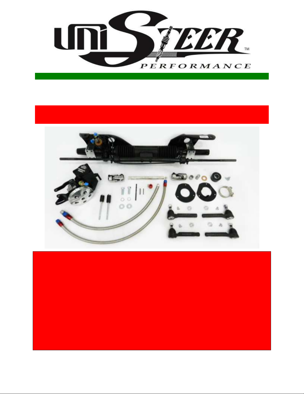
’67-‘70 Cougar Rack Kit Instructions
# 8011950-01 & 8011940-01
Full refund will NOT be granted to any kits that are damaged,
scratched, or altered in any fashion.
*USE ONLY POWER STEERING FLUID IN SYSTEM. DO NOT USE ATF.
*ALTHOUGH THIS KIT IS FAIRLY SIMPLE TO INSTALL, SOME MODIFICATIONS
MAYBE NECESSARY.
*BEFORE STARTING INSTALLATION, PLEASE BE AWARE OF THE
MODIFICATIONS THAT ARE NEEDED TO INSTALL.
*MUST USE A MINI STARTER (I.E. POWER MASTER) ON SMALL BLOCK
EQUIPED CARS
**USED HOOKER SUPER COMPS HEADERS ON BIG AND SMALL BLOCK WITH
FACTORY FOUR SPEED TRANSMISSION AND LINKAGE.
*DUE TO VARIABLES OUTSIDE OUR CONTROL THESE KITS MAY NOT FIT ALL
APPLICATIONS. ALSO, PLEASE VERIFY KIT WILL FIT YOUR APPLICATION
BEFORE ALTERING VEHICLE.
Page 1 656790
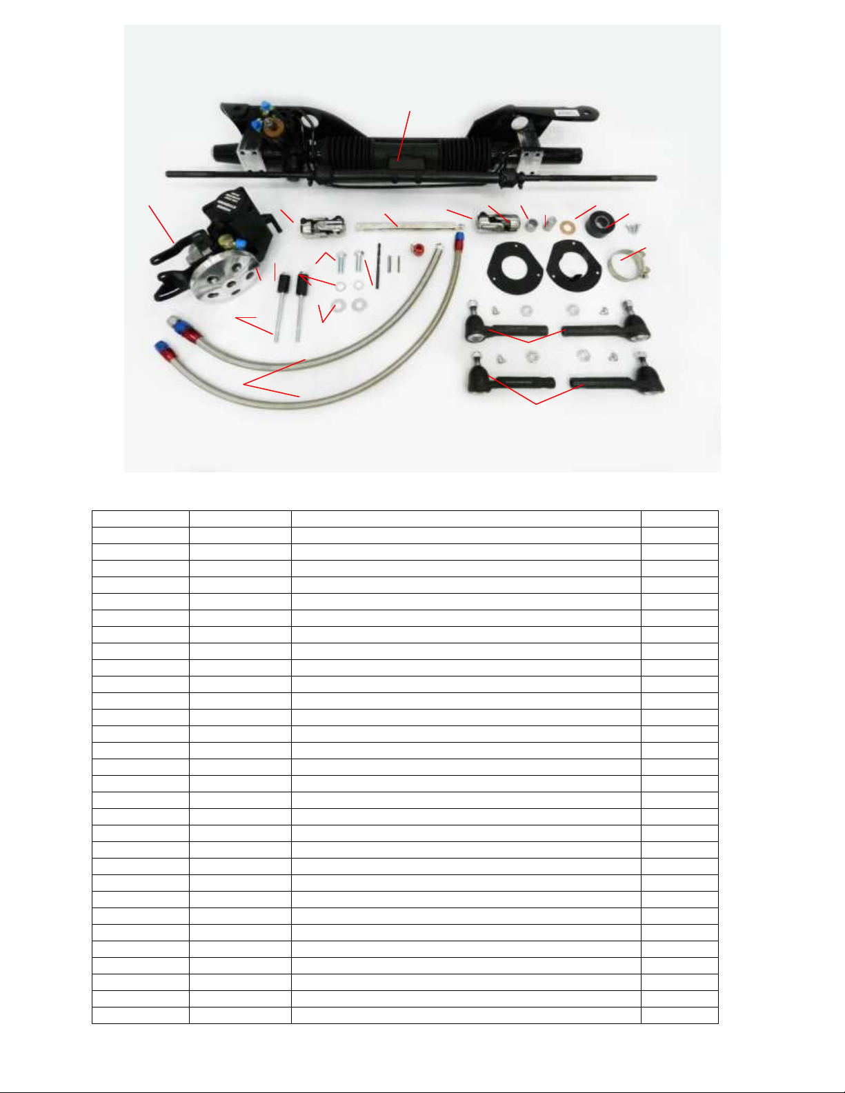
KIT CONTENTS:
#
Part Number
Description
Quantity
1
8011950-01
Rack and Pinion Unit w/bracket
1
2a
8060710
Pump Assembly for Small Block
1
2b
8060670
Pump Assembly for Big Block
1
3
8021310
Pump Line Kit
1
4a
201090
5/16” Lock Washer for Small Block
2
4b
200840
3/8” Lock Washer for Big Block
2
5
200850
5/16” Flat Washer
2
6a
231780
5/16-18 x 5 1/2” hex bolt for Small Block
2
6b
230660
3/8”-16 x 1” bolt for Big Block
1
6c
231660
3/8”-16 x 2 ¼” bolt for Big Block
1
7
206270
Pump Assembly Standoff-1.365” for Small Block only
1
8a
206070
Pump Assembly Standoff-1.625” for Small Block
1
8b
205990
Pump Assembly Standoff for Big Block
1
9
130330
Column Clamp
1
10
8021270
Column Bracket
1
11
205720
Column Gasket
1
12
231130
Screws ¼” x 14 x ¾”
3
13
205780
Column Bushing and Bearing
1
14
8051410
U-joint 9/16-30 x ¾” round
1
15
8050640
U-joint 17mmdd x 3/4dd
1
16
549210
Shaft 3/4dd x 9 1/2”- 9/16-30 spline
1
17
200860
7/16” Flat Washer
2
18
200150
½” Internal Star Washer
2
19
231120
Bolt ½” x 13 x 1 ½”
2
20
8021320
Outer Tie Rod Small Taper
2
21
8021330
Outer Tie Rod Small Taper
2
22
480260
Thrust Washer
1
23
545030
Column Insert (for 1970 column only)
1
24
620630
Drill Bit and Roll Pin u-joint install kit
1
25
545310
U-Joint Bushing (may not be needed)
1
14 1 2 3 9
10
12
13 8 7
15
16
18
20
21
22
23
25
Page 2 656790
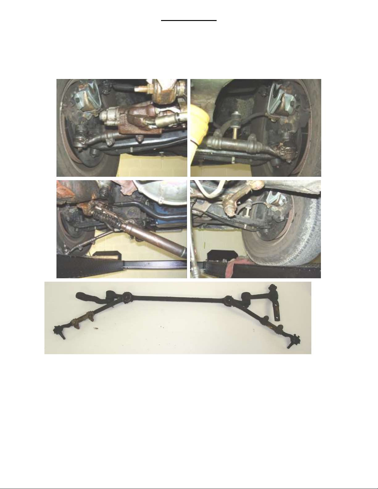
Disassembly:
The first step is to disassemble and remove the stock steering linkage, steering box and column.
1. Disconnect steering shaft from steering box. Raise vehicle and support it on stands. Note be sure not
to put the stand in a location by the stock round cross member.
2. Remove the cotter pins and nuts from outer tie rod ends and remove tie rods from spindles.
Disconnect the center link and idler arm assembly from the frame and remove the entire steering
linkage.
3. Remove bolts retaining the gearbox to the frame and remove the box. If equipped remove the power
steering pump, brackets and lines. All the pieces removed will not be used.
Page 3 656790
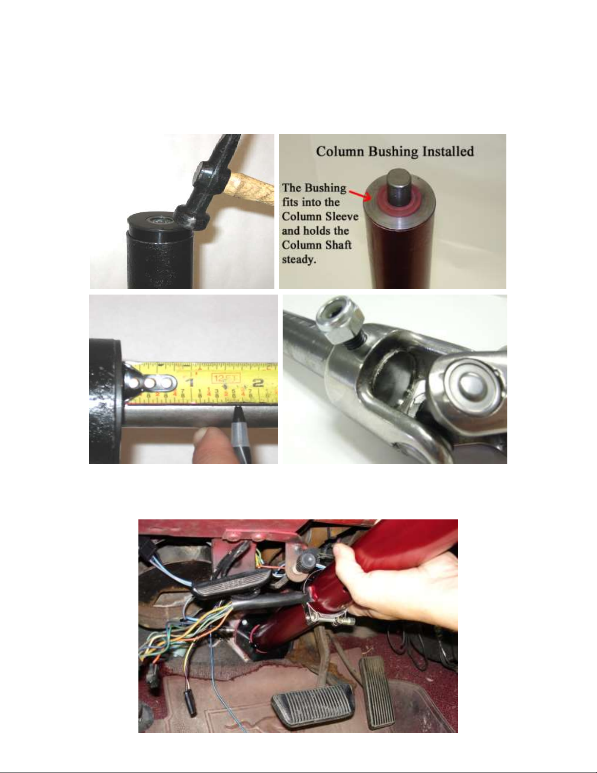
4. You need to modify your stock column slightly. If you have an Early 1967 or 1970 refer to the
appropriate section at the end of the instruction sheet. Remove the steering column and tube
assembly in one piece. Do not remove the steering wheel. Cut off the rag joint assembly at the end
closest to the joint itself. Next install the supplied column tube bearing by sliding it over the steering
shaft and up to the column tube and tap it in with a hammer. Once the bearing is seated measure from
the flat of the bearing down 1-3/4” and cut off the excess shaft. Next slide on the brass washer and
install the supplied U-joint so that the shaft is flush to the inside of the new joint. Drill and pin the
joint in place with the provided bit and roll pins. That is all that is needed for modification to the
column.
5. Once you have this done install the appropriate floor plate provided in your kit using the hardware
provided. Slide the floor plate over the column tube with the clamp and install the column through the
firewall and bolt back in place. Attach the new floor plate with supplied hardware and complete the
installation.
Page 4 656790
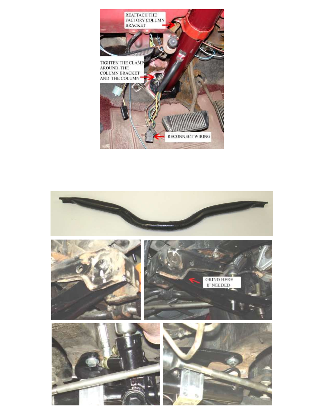
6. From under the car remove the stock round cross member from the frame rail to frame rail. Install the
new power rack and bracket in place using the stock holes where the cross member was and install
new hardware provided. Note: Always check to make sure that your bracket is clear of the control
arms and the lip of the frame around the camber adjusting bolts. If the bracket rubs or hits anywhere
it is necessary to grind a little of the edge of the rolled lips of the metal on these parts. DO NOT
GRIND ON THE SUPPLIED BRACKET.
Page 5 656790
 Loading...