

UTC TL431A LINEAR INTEGRATED CIRCUIT
PROGRAMMABLE PRECISION
REFERENCE
DESCRIPTION
The UTC TL431A is a three-terminal adjustable regulator
with a guaranteed thermal stability over applicable
temperature ranges. The output voltage may be set to any
value between Vref(approximately 2.5V) and 36V with two
external resistors. It provides very wide applications,
including shunt regulator, series regulator, switching
regulator, voltage reference and others.
FEATURES
*Programmable output Voltage to 36V.
*Low dynamic output impedance 0.2Ω.
*Sink current capability of 1 to 100mA.
*Equivalent full-range temperature coefficient of 50ppm/ °C
typical for operation over full rated operating temperature
range.
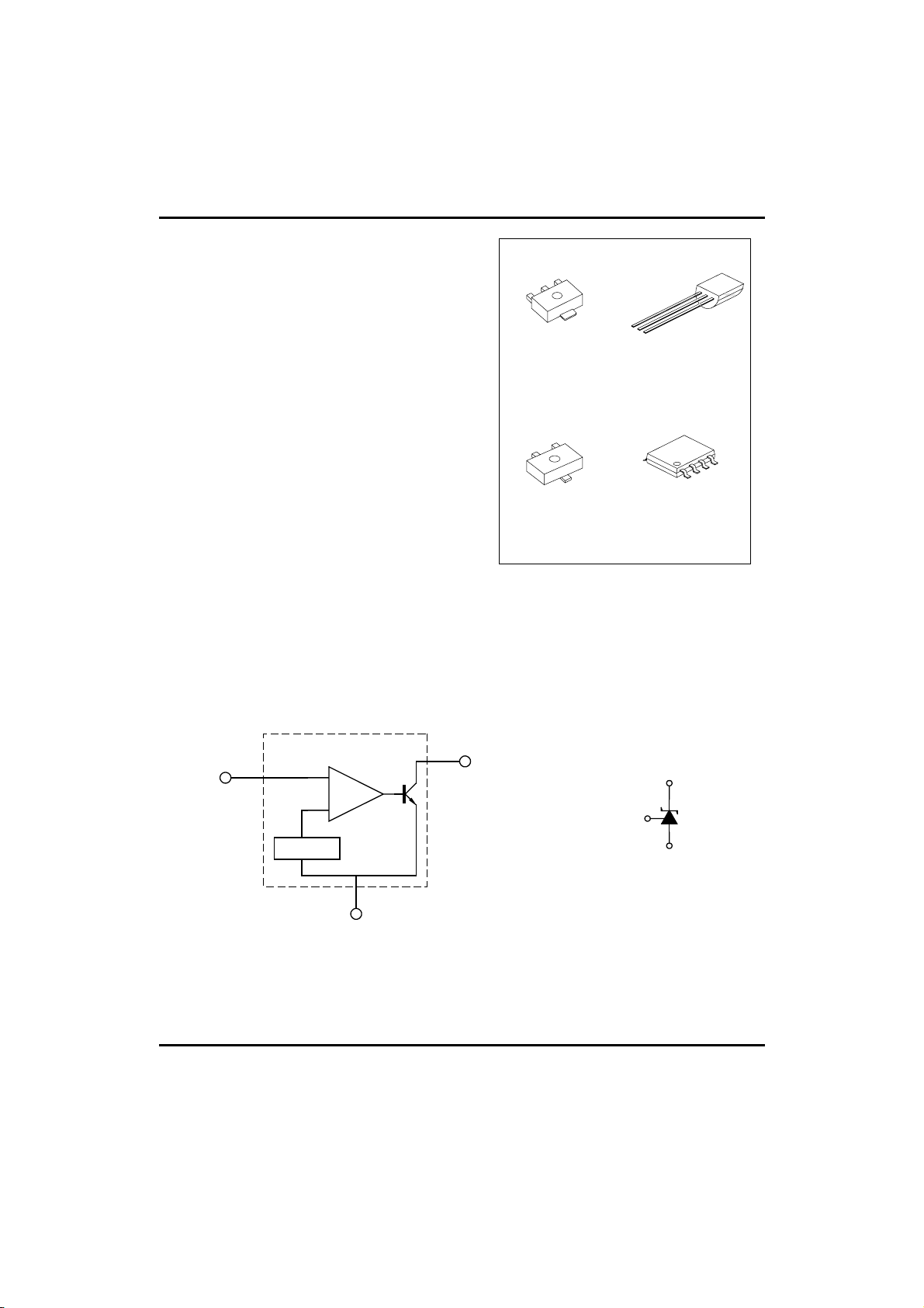
BLOCK DIAGRAM
CATHODE
REFERENCE
1
1
SOT-89
2
1
3
SOT-23
SOP-8 1: Cathode 2,3,6,7: Anode 8: Ref.
4,5: N.C.
TO-92 1: Ref ; 2: Anode; 3: Cathode
SOT-89 1: Ref ; 2: Anode; 3: Cathode
SOT-23 1: Cathode; 2: Ref; 3: Anode
*Pb-free plating product number: TL431AK
REFERENCE
(R)
TO-92
SOP-8
CATHODE
(K)
2.5V Vref
ANODE
ANODE(A)
UTC UNISONIC TECHNOLOGIES CO., LTD. 1
QW-R103-007,D
UTC TL431A LINEAR INTEGRATED CIRCUIT
ABSOLUTE MAXIMUM RATINGS
PARAMETER SYMBOL VALUE UNIT
Cathode Voltage VKA 37 V
Cathode Current Range(Continuous) IKA -100 ~ +150 mA
Reference Input Current Range Iref -0.05 ~ +10 mA
Operating Junction Temperature Tj 150 °C
Operating Ambient Temperature Topr -40 ~ +85 °C
Storage Temperature Temperature Tstg -65 ~ +150 °C
RECOMMENDED OPERATING CONDITIONS
PARAMETER SYMBOL MIN TYP MAX UNIT
Cathode Voltage VKA VREF 36 V
Cathode Current IKA 1 100 mA
ELECTRICAL CHARACTERISTICS (Ta=25°C, unless otherwise specified)
PARAMETER SYMBOL TEST CONDITIONS MIN TYP MAX UNIT
Reference Input Voltage Vref VKA=VREF,IKA=10mA
Deviation of reference Input Voltage
Over temperature(note 1)
Ratio of Change in Reference Input
Voltage to the Change in Cathode
Voltage
Reference Input Current Iref IKA=10mA,R1=10kΩ, R2=∞ 1.5 4 µA
Deviation of Reference Input Current
Over Full Temperature Range
Minimum Cathode Current for
Regulation
Off-State Cathode Current IKA(OFF) VKA=36V,VREF=0 0.05 1.0 µA
Dynamic Impedance ZKA VKA=VREF, IKA=1 to 100mA
Note:TMIN=0°C,TMAX=+70°C
(Operating temperature range applies unless otherwise specified))
∆Vref/∆T VKA=VREF,IKA=10mA
∆Vref /∆VKA IKA=10mA
∆Iref/∆T IKA=10mA,R1=10kΩ, R2=∞
IKA(min) VKA=VREF
TMIN<=TA<=TMAX
∆VKA=10V~VREF
∆VKA=36V~10V
TA=full Temperature
f≤1.0kHz
2.483 2.495 2.507 V
4.5 17 mV
-1.0
0.4 1.2 µA
0.45 1.0 mA
0.15 0.5 Ω
-0.5
-2.7
-2.0
mV/V
UTC UNISONIC TECHNOLOGIES CO., LTD. 2
QW-R103-007,D

UTC TL431A LINEAR INTEGRATED CIRCUIT
TYPICAL PERFORMANCE CHARACTERISTICS
Fig 1 Cathode Current Vs Cathode Voltage
Ta=25℃
125
KA=VREF
V
100
75
50
25
0
-25
Cathode Current (mA)
-50
-75
-100
-2 -1 0 1 2 3
Cathode Voltage (V)
Fig 2 Cathode Current Vs Cathode Voltage
800
Ta=25℃
KA=VREF
V
600
400
200
Cathode Current (mA)
0
-200
-2
-1 1023
Cathode Voltage (V)
IKA(min)
Fig 3 Change in Reference Input Voltage
0
-5
-10
-15
-20
-25
Voltage (mV)
-30
Change In Reference INput
-35
-40
0 5 10 15 20 25 30 35 40
Vs Cathode voltage
Cathode Voltage (V)
Fig 5 Dynamic Impedance
2
10
Ta=25℃
I
1
10
Impedance (Ω)?
0
10
-1
10
3
10
KA=0mA to 100mA
Vs Frequency
4
1010
Frequency (Hz)
5
IKA=100mA
Ta=25℃
6
10
Fig 4 Pulse Response
7
6
5
4
3
2
Input and Output Voltage (V)
1
0
Ta=25℃
01234567
Time (µ s)
Fig 6 Small Signal Voltage Amplification Vs Frequency
70
60
50
40
30
20
10
Voltage Amplification (dB)
0
7
10
-10
3
10
Ta=25℃
I
KA=10mA
4
5
1010
6
10
7
10
Frequency (Hz)
UTC UNISONIC TECHNOLOGIES CO., LTD. 3
QW-R103-007,D

UTC TL431A LINEAR INTEGRATED CIRCUIT
I
TEST CIRCUIT
INPUT
V
REF
Fig 7 Test Circuit For V
APPLICATION CIRCUIT
Vi Vo
R1
V
KA
I
KA
UTC TL431A
KA=VREF Fig 8 Test Circuit for VKA >= VREF Fig 9 Test Circuit For IKA(OFF)
INPUT V
R1
I
REF
V
REF
R2
V
KA=VREF*(1+R1/R2)+IREF*
IN
UTC7805
OUT
Vi
COMMON
KA
I
KA
UTC TL431A
R1
Vo
R1
INPUT
Vi
R1
Vo
I
KA(OFF)
V
KA
UTC TL431A
REF
V
R2
UTC TL431A
Vo=(1+R1/R2)*V
REF
Vo=(1+R1/R2)*V
UTC TL431A
REF
V
REF
R2
REF
V
R2
UTC TL431A
Vo=(1+R1/R2)*V
REF
Fig 10 Shutdown Regulator Fig 11 Output Control of a Three Fig 12 Higher-current Shunt Regulator
-Terminal Fixed Regulator
Vi
Io
Vo
Vi
o
RCL
Vo
Rs
UTC TL431A
Rs
IO=V
REF/RS
UTC TL431A
R
S=VREF
/RCL
Fig 13 Constant-current Sink Fig 14 Current Limiting or Current Source
UTC UNISONIC TECHNOLOGIES CO., LTD. 4
QW-R103-007,D

UTC TL431A LINEAR INTEGRATED CIRCUIT
UTC assumes no responsibility for equipment failures that result from using products at values that
exceed, ev en momentarily, rated values (such as maximum ratings, operating condition ranges, or
other parameters) listed in products specifications of any and all UTC products described or contained
herein. UTC products are not designed for use in life support appliances, devices or systems where
malfunction of these products can be reasonably expected to result in personal injury. Reproduction in
whole or in part is prohibited without the prior written consent of the copyright owner. The information
presented in this document does not form part of any quotation or contract, is believed to be accurate
and reliable and may be changed without notice.
UTC UNISONIC TECHNOLOGIES CO., LTD. 5
QW-R103-007,D
 Loading...