

现货库存、技术资料、百科信息、热点资讯,精彩尽在鼎好!
UNISONIC TECHNOLOGIES CO., LTD
LM318 LINEAR INTEGRATED CIRCUIT
HIGH SPEED OPERATIONAL
AMPLIFIER
DESCRIPTION
The UTC LM318 is a precision, high speed, high gain operational
amplifier that has been specifically designed for use in high slew rate
and wide bandwidth applications. Unlike many wideband amplifiers,
the UTC LM318 is unity-gain stable since it has internal circuitry for
frequency compensation. However, external components may be
added for compensation to achieve optimum performance.
When used in inverting applications, feed-forward compensation
can be used to achieve slew rate in excess of 150V/µs and almost
double the bandwidth. For greater stability, using overcompensation
with the amplifier is possible if maximum bandwidth is not needed. In
general, by adding a single capacitor can reduce the settling time for
0.1% error band to under 1µs.
The typical applications of UTC LM318 include A/D converters,
fast integrator, oscillators, active filters, sample and hold circuits, or
general purpose amplifiers.
*Pb-free plating product number: LM318L
FEATURES
* Unit gain stable (internal frequency compensation)
* 4mV typical input offset voltage
* 30nA typical input offset current
* Input bias current of 250nA (maximum)
* 15MHz bandwidth (small signal)
* 50V/μs slew rate (guarantee)
* Operates voltages of ±5V to ±20V
* Overload protection for Input and output
* Same pin assignment as general-purpose op amps
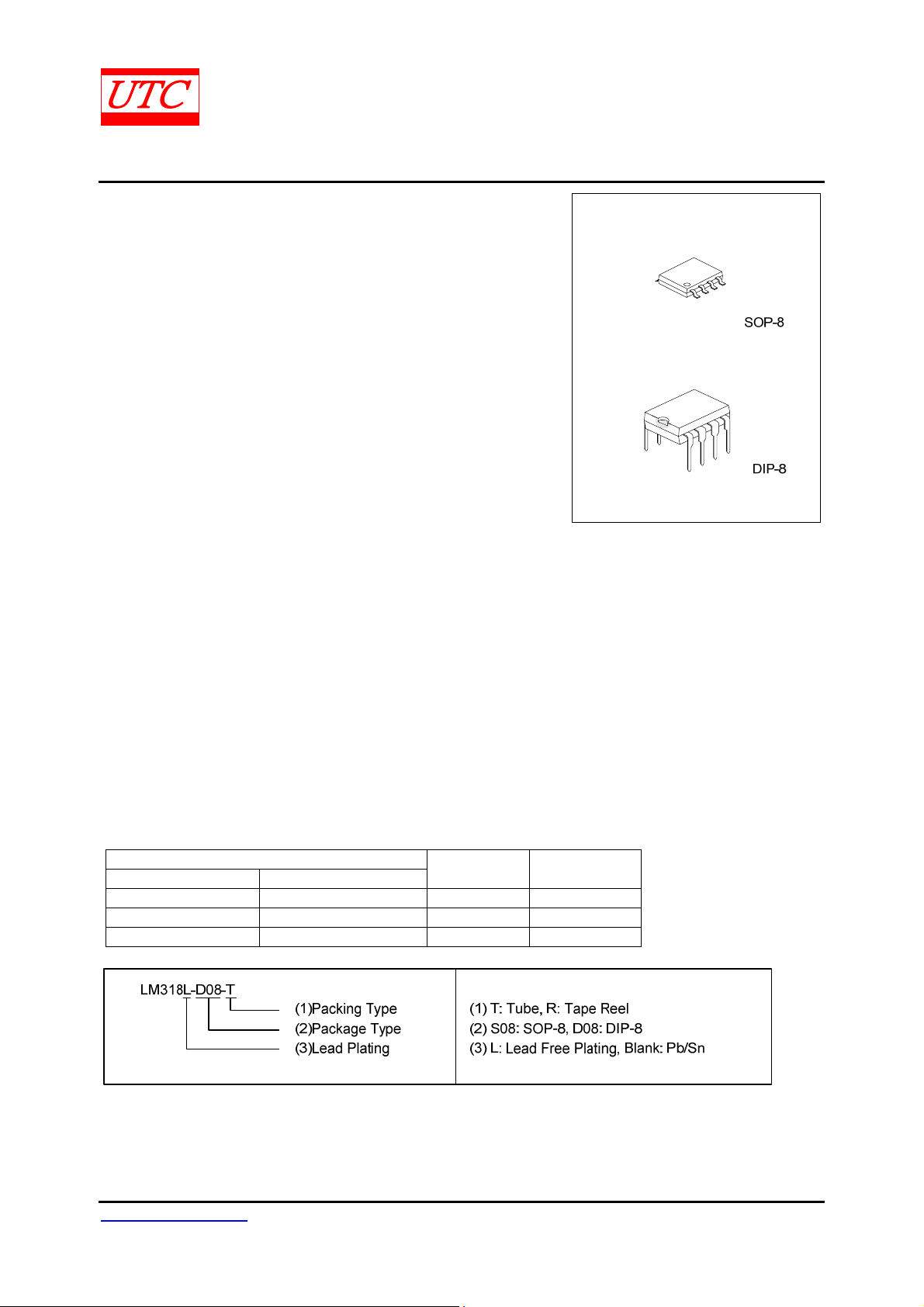
ORDERING INFORMATION
Order Number
Normal Lead Free Plating
LM318-D08-T LM318L-D08-T DIP-8 Tube
LM318-S08-R LM318L-S08-R SOP-8 Tape Reel
LM318-S08-T LM318L-S08-T SOP-8 Tube
Package Packing
www.unisonic.com.tw 1 of 6
Copyright © 2005 Unisonic Technologies Co., Ltd QW-R105-016,C
LM318 LINEAR INTEGRATED CIRCUIT
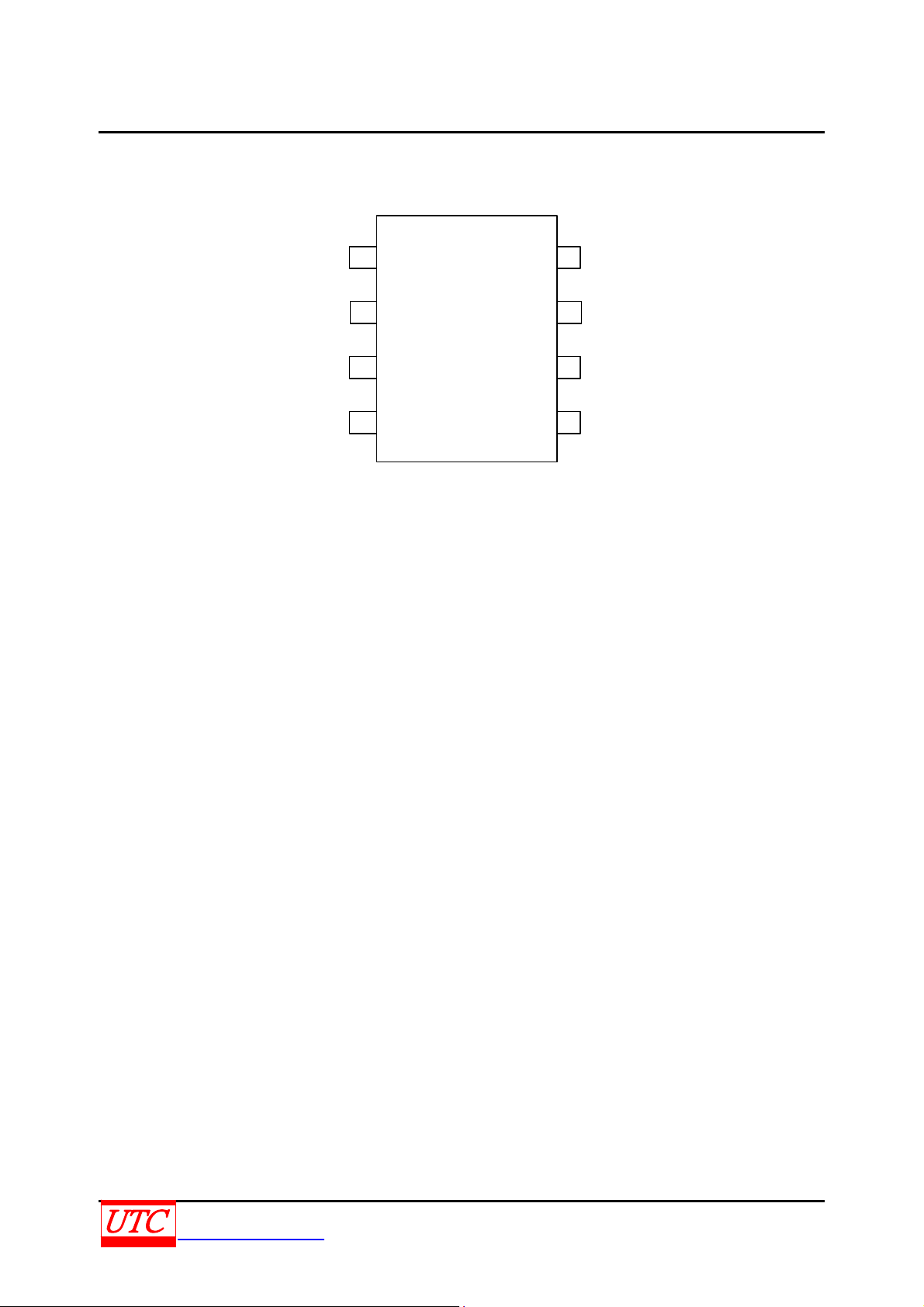
PIN CONFIGURATIONS
COMP-1
IN-
IN+
VCC-
COMP-2
1
3
45
8
7
6
VCC+2
OUTPUT
COMP-3
UNISONIC TECHNOLOGIES CO., LTD 2 of 6
www.unisonic.com.tw QW-R105-016,C

LM318 LINEAR INTEGRATED CIRCUIT
SCHEMATIC DIAGRAM
+
UNISONIC TECHNOLOGIES CO., LTD 3 of 6
www.unisonic.com.tw QW-R105-016,C

LM318 LINEAR INTEGRATED CIRCUIT
ABSOLUTE MAXIMUM RATINGS
PARAMETER SYMBOL RATINGS UNIT
Supply Voltage V
Supply Voltage V
Input Voltage (Note 2) VIN ±15 V
Differential Input Current (Note 3) I
Power Dissipation PD 500 mW
Output Short-Circuit Duration Continuous
Maximum Junction Temperature TJ 110 °C
Operating Temperature Range T
Storage Temperature Range T
Note:1.Absolute maximum ratings are those values beyond which the device could be permanently damaged.
Absolute maximum ratings are stress ratings only and functional device operation is not implied.
2.For supply voltage less than ±15V, the absolute maximum input voltage is equal to the supply voltage.
3.The inputs are shunted with two opposite-facing base-emitter diodes for over voltage protection. Therefore,
excessive current flows if a differential input voltage in excess of 1V is applied between the inputs unless
some limiting resistance is used.
+20 V
CC+
-20 V
CC-
±10 mA
I(DIFF)
0 ~ +70 °C
OPR
-65 ~ +150 °C
STG
ELECTRICAL CHARACTERISTICS (±5V≤ V
≤±20V, 0°C≤T
CC
≤+70°C, unless other specifics)
A
PARAMETER SYMBOL TEST CONDITION MIN TYP MAX UNIT
Input Voltage Range VIN VCC=±15V ±11.5 V
Output Voltage Swing V
Input Offset Voltage V
Large Signal Voltage Gain GV
Input Offset Current I
Input Bias Current I
VCC =±15V, RL=2KΩ ±12 ±13 V
OUT
TA=25°C 4 10 mV
I(OFF)
I(OFF)
I(BIAS)
15 mV
TA=25°C, VCC =±15V
V
=±10V, RL≥2KΩ
OUT
V
=±15V, V
cc
TA=25°C 30 200 nA
300 nA
TA=25°C 150 500 nA
750 nA
=±10V, RL≥2KΩ 20 V/mV
OUT
25 200 V/mV
Supply Current ISS TA=25°C 5 10 mA
Input Resistance RS TA=25°C 0.5 3 MΩ
Slew Rate SR TA=25°C, VCC =±15V, Gv=1 50 70 V/µs
Small Signal Bandwidth SBW TA=25°C, VCC =±15V 15 MHz
Common Mode Rejection Ratio CMRR 70 100 dB
Supply Voltage Rejection Ratio SVRR 65 80 dB
Note: These power supplies must be bypassed with 0.1µF(or larger) disc ceramic capacitor within an inch of the
device.
UNISONIC TECHNOLOGIES CO., LTD 4 of 6
www.unisonic.com.tw QW-R105-016,C

LM318 LINEAR INTEGRATED CIRCUIT
TYPICAL CHARACTERISTICS
190
150
100
50
40
30
20
10
0
070605040302010
Input Current
BIAS
OFFSET
Temperature (℃)
Voltage Gain
115
TA=25℃
110
105
100
95
5
Supply Voltage (±V)
15 2010
UNISONIC TECHNOLOGIES CO., LTD 5 of 6
www.unisonic.com.tw QW-R105-016,C

LM318 LINEAR INTEGRATED CIRCUIT
TYPICAL CHARACTERISTICS(Cont.)
Power Dissipation vs. Ambient Temperature
600
500
400
300
200
100
Power Dissipation, PD(mW)
0
0 20 40 60 80 100 120 140
Ambient Temperature(C)
)
A
n
(
t
n
e
r
r
u
C
t
u
p
n
I
600
400
200
0
-200
-400
-600
-0.8 -0.4 -0.2-0.6
Input Current
00.60.80.40.2
Differential Input (V)
UTC assumes no responsibility for equipment failures that result from using products at values that
exceed, even momentarily, rated values (such as maximum ratings, operating condition ranges, or
other parameters) listed in products specifications of any and all UTC products described or contained
herein. UTC products are not designed for use in life support appliances, devices or systems where
malfunction of these products can be reasonably expected to result in personal injury. Reproduction in
whole or in part is prohibited without the prior written consent of the copyright owner. The information
presented in this document does not form part of any quotation or contract, is believed to be accurate
and reliable and may be changed without notice.
UNISONIC TECHNOLOGIES CO., LTD 6 of 6
www.unisonic.com.tw QW-R105-016,C
 Loading...