

现货库存、技术资料、百科信息、热点资讯,精彩尽在鼎好!
UNISONIC TECHNOLOGIES CO., LTD
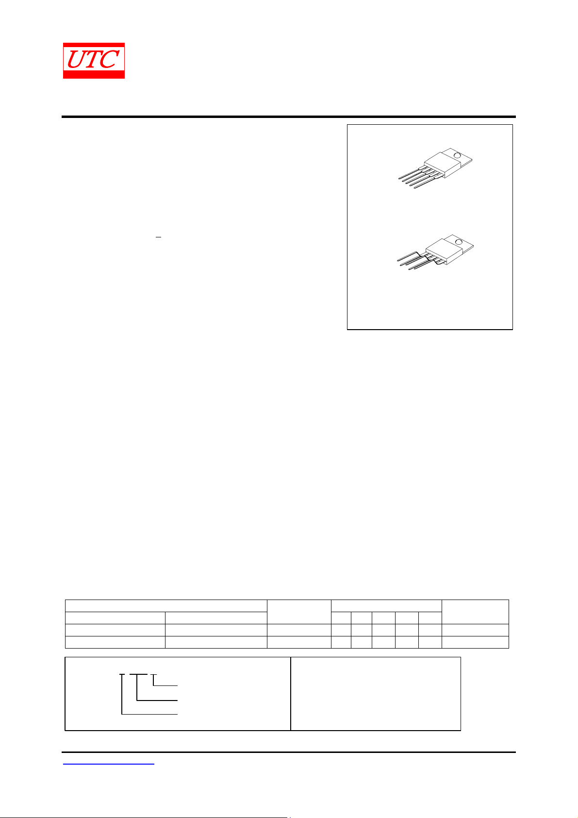
LM1875
20W AUDIO POWER AMPLIFIER
DESCRIPTION
The UTC LM1875 is a monolithic power amplifier offering very
low distortion and high quality performance for consumer audio
applications. It delivers 20W into a 4Ω or 8Ω load on ±25V supplies.
Using an 8Ω load and +30V supplies, over 30W of power may be
delivered. The amplifier is designed to operate with a minimum of
external components. Device overload protection consists of both
internal current limit and thermal shutdown.
The UTC LM1875 design utilizes advanced circuit techniques
and processing to achieve extremely low distortion levels even at
high output power levels. Other outstanding features include high
gain, fast slew rate and a wide power bandwidth, large output
voltage swing, high current capability, and a very wide supply range.
The amplifier is internally compensated and stable for gains of 10 or
greater.
FEATURES
*Up to 30W output power
*Avo typically 90 dB
*Low distortion: 0.015%,1kHz,20W
*Wide power bandwidth: 70kHz
*Protection for AC and DC short circuits to ground
*Thermal protection with parole circuit
*High current capability: 4A
*Wide supply range 16V-60V
*Internal output protection diodes
*94 dB ripple rejection
LINEAR INTEGRATED CIRCUIT
1
TO-22 0-5
1
TO-220B
*Pb-free plating product number: LM1875L
APPLICATIONS
*High performance audio systems
*Bridge amplifiers
*Stereo phonographs
*Servo amplifiers
*Instrument systems
ORDERING INFORMATION
Order Number Pin Assignment
Normal Lead Free Plating
LM1875-TA5-T LM1875L-TA5-T TO-220-5 +IN -IN -VEEOUT VCC Tube
LM1875-TB5-T LM1875L-TB5-T TO-220B +IN -IN -VEEOUT VCC Tube
Package
1 2 3 4 5
Packing
LM1875L-TA5-T
(1)Packing Type
(2)Package Type
(3)Lead Plating
(1) T: Tube
(2) TA5: TO -2 20-5, TB5: TO-220B
(3) L: Lead Free Plating, Blank: Pb/Sn
www.unisonic.com.tw 1 of 7
Copyright © 2005 Unisonic Technologies Co., Ltd
QW-R107-019,D
LM1875
LINEAR INTEGRATED CIRCUIT
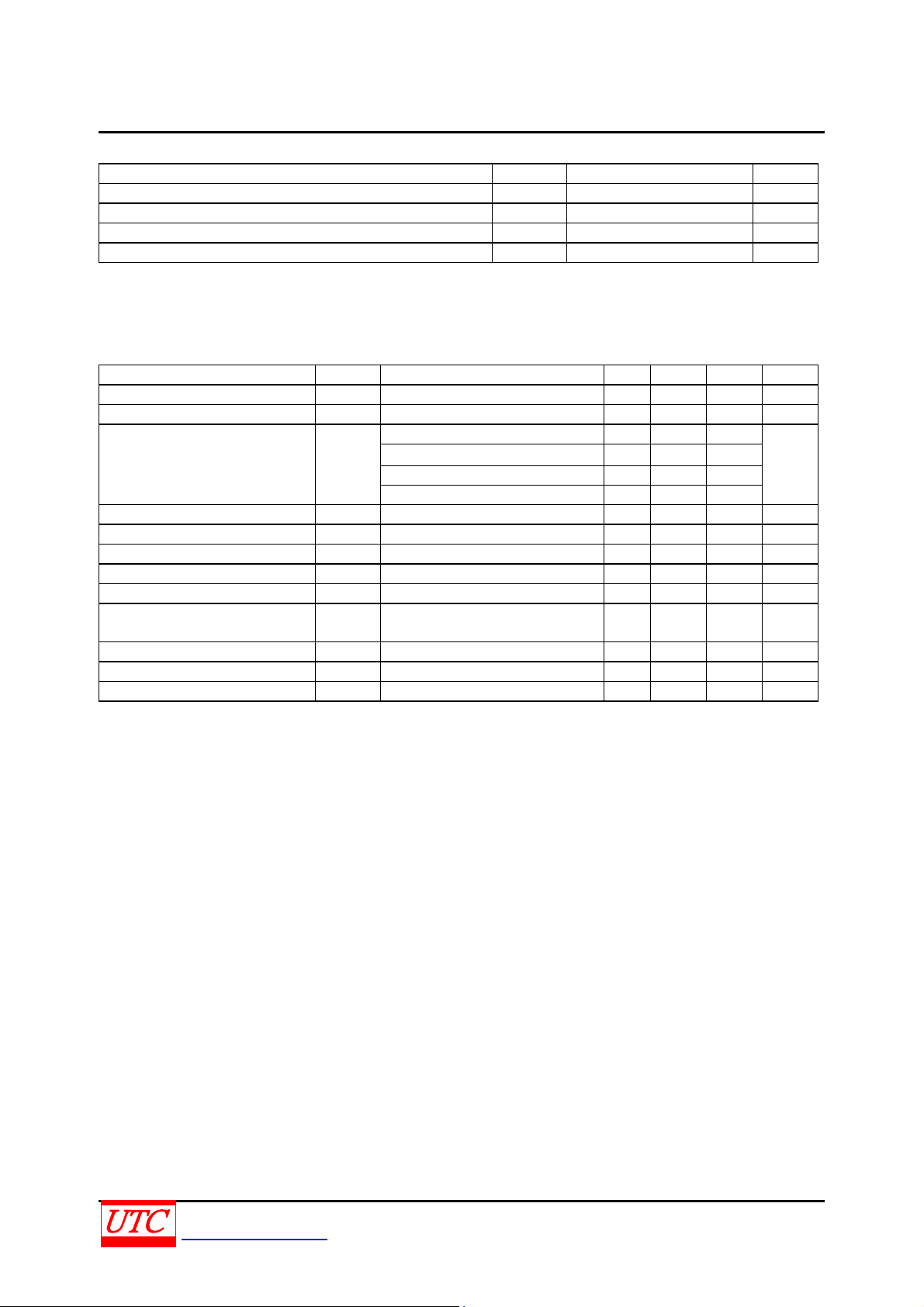
ABSOLUTE MAXIMUM RATINGS
(Ta=25℃)
PARAMETER SYMBOL RATING UNIT
Supply Voltage VCC 60 V
Input Voltage VIN -VEE ~ VCC V
Junction Temperature TJ +150 ℃
Storage Temperature T
-40 ~ +150
STG
℃
Note Absolute maximum ratings are those values beyond which the device could be permanently damaged.
Absolute maximum ratings are stress ratings only and functional device operation is not implied.
ELECTRICAL CHARACTERISTICS
(VCC=+25V,-VEE=-25V,Ta=25℃,RL=8Ω,Av=20(26dB),fo=1kHz,unless otherwise specified.)
PARAMETER SYMBOL TEST CONDITIONS MIN TYP MAX UNIT
Supply Current ICC P
Output Power(Note) P
Total Harmonic Distortion
(Note)
Offset Voltage V
Input Bias Current I
Input Offset Current I
THD=1% 25 W
OUT
THD
O(OFF)
±0.2 ±2 µA
I(BIAS)
0 ±0.5 µA
I(OFF)
=0W 70 100 mA
OUT
P
=20W,fo=1kHz 0.015
OUT
P
=20W, fo =20kHz 0.05 0.4
OUT
P
=20W,RL=4Ω,fo=1kHz 0.022
OUT
P
=20W,RL=4Ω,fo=20kHz 0.07 0.6
OUT
%
±1 ±15 mV
Gain-Bandwidth Product GBW Fo=20kHz 5.5 MHz
Open Loop Gain Gv DC 90 dB
Power Supply Rejection Ratio RR
V
CC
V
,1kHz,1 Vrms
EE
52
52
95
83
dB
,1kHz,1 Vrms
Max Slew Rate SR 20W,8Ω,70kHz BW 8 V/µs
Current Limit I
LIMIT
V
OUT=VSUPPLY
–10V 3 4 A
Equivalent Input Noise Voltage eN Rs=600Ω,CCIR 3 µVrms
Note: Assumes the use of a heat sink having a thermal resistance of 1 /W and no ℃insulator with an Ta=25 .℃
Because the output limiting circuitry has a negative temperature coefficient, the maximum output power
delivered to a 4Ω load may be slightly reduced when the tab temperature exceeds 55 .
℃
UNISONIC TECHNOLOGIES CO., LTD
www.unisonic.com.tw
2 of 7
QW-R107-019,D
LM1875
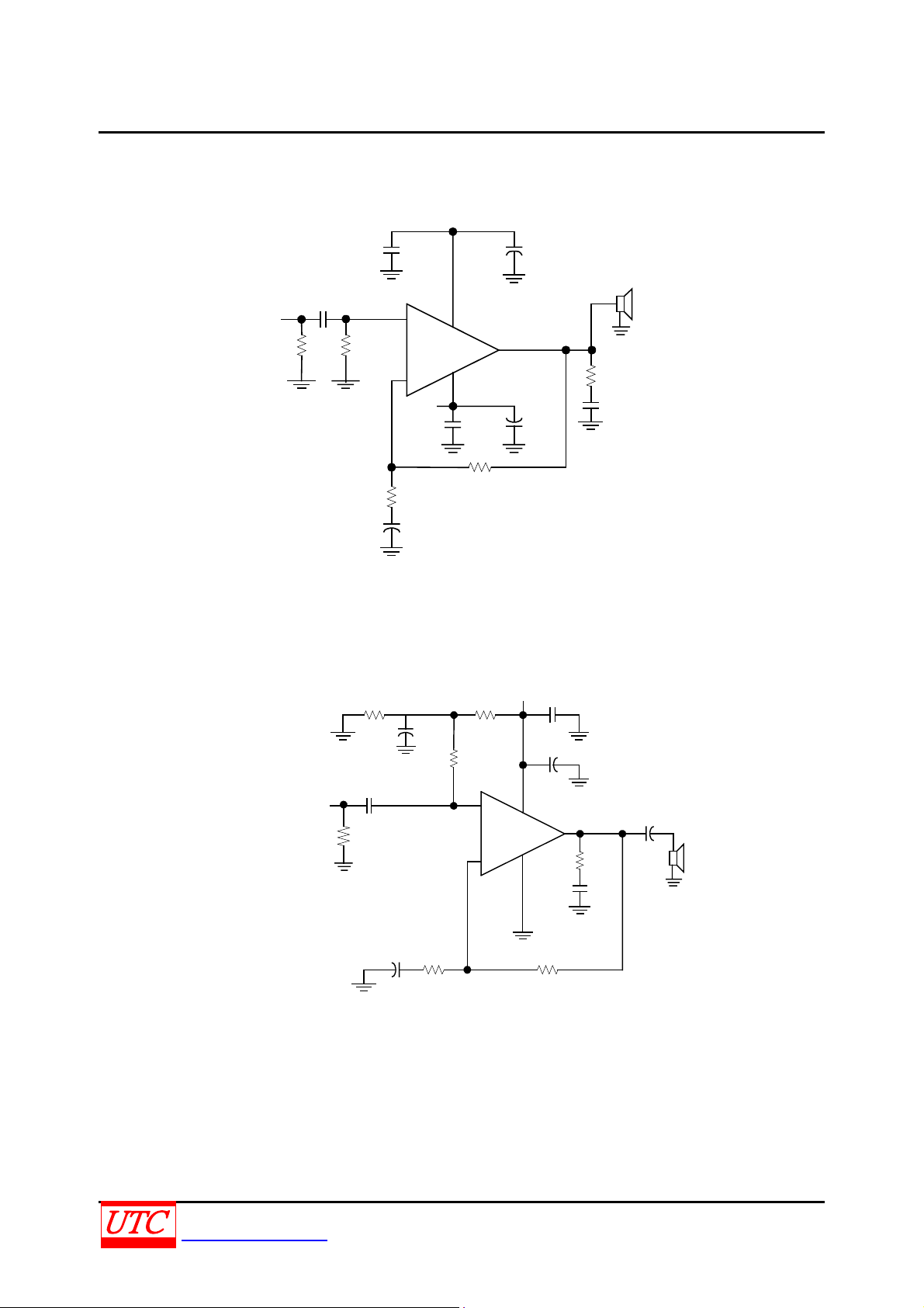
TYPICAL APPLICATION CIRCUIT
+Vcc
C3 C7
0.1μF
C1
2.2μF
V
IN
R1
1M
TYPICAL SINGLE SUPPLY OPERATION
IN
V
R2
22k
R1
22k
C1
1.0μF
R4
1M
+
1
+
2
_
EE
-V
0.1μF
R3 1K
C2
22μF
+
C2
10μF
LM1875
C4
5
3
R3
22k
R4
20k
1
2
22k
R2
+
LM1875
_
LINEAR INTEGRATED CIRCUIT
+
4
+
+Vcc
C6
100μF
C4
0.1μF
C7
+
5
R7
3
0.22μF
100μF
100μF
4
1
C5
4Ω~8Ω
R5
1
C5
0.22μF
C6
2200μF
+
4Ω~ 8Ω
C3
10μF
R5
10k
+
UNISONIC TECHNOLOGIES CO., LTD
www.unisonic.com.tw
R6
200k
3 of 7
QW-R107-019,D

LM1875
TYPICAL CHARACTERISTICS
LINEAR INTEGRATED CIRCUIT
THD vs Power Output
1.0
0.1
Total Harmoni c Di stortion (%)
0.01
35
30
25
20
0.1
RL =8Ω
THD=1%
1.0
Power Output (W)
Power Output vs Supply Voltage
10 100
0.1
0.09
0.08
0.07
0.06
0.05
THD(%)
0.04
0.03
0.02
0.01
100
60
0
20 100
80
THD vs Supply Voltage
Vs=+ 25V
PD=10W
RL=4Ω
RL=8Ω
50
Supply Current vs Supply Voltage
500
200 1K
Frequency (Hz)
2K
5K 10K 20K
15
10
Power Output (W)
5
0
100
90
80
70
60
RR (dB)
50
40
30
20
10
0
5
010
POSITIVE SUPPLY
INPUT REFERRED
RS =0
L=4
R
1 Vrms
20 100
15
20 25
Supply Voltage (+V)
RR vs Frequency
NEGATIVE SUPPLY
50050 200 1K
Frequency (Hz)
2K 5K 10K 20K
30
40
Supply Current (mA)
20
0
010
Device Dissipation vs Ambient Temperature
45
40
35
30
25
20
15
Device Dissipation ( W)
10
5
0
0
INFINITE HEAT SINK
5℃/W
HEAT SIN K
10℃/W HEAT SINK
40
20 60
Ta - Ambient Temperture (℃)
See Application Hints .
1552025
Supply Voltage (±V)
1℃/W HEAT SINK
HEAT SINK
80
100
Interface=1℃/W
30
2℃/W
120 140 160
UNISONIC TECHNOLOGIES CO., LTD
www.unisonic.com.tw
4 of 7
QW-R107-019,D

LM1875
TYPICAL CHARACTERISTICS (Cont.)
Power Disipation vs Power Output
50
45
40
35
30
25
20
15
Po we r Dissipati o n (W)
10
5
0
010
Vs=+15V
5
Powe r Outp ut (W)
I
OUT
vs V
Safe Operating Area Boundary
6
4
2
0
-2
Outp ut Current (A)
-4
-6
-25 -15
Output Voltage (V)
Vs=+30V
Vs=+25V
Vs=+20V
15
OUT
-Current Limit/
-5-20 -10 0
51015
R
L
=4Ω
fo=1kHz
20 25 30
20
25
LINEAR INTEGRATED CIRCUIT
Power Disipation vs Power Output
50
R
L
=8Ω
45
fo=1kHz
40
35
30
25
20
15
Power Dissipation (W)
10
5
0
010
5
Open Loop Gain and Phase vs
30
25
20
15
10
5
Gain (dB)
0
-5
-10
-15
-20
100k
Vs=+ 15V
15
Power Output (W)
Frequency
1M
Frequency (Hz)
Vs=+30V
Vs=+25V
Vs=+20V
20 25 30
10M
180
135
90
45
0
-45
-90
-135
-180
Ohase Lag (Degrees)
Input Bias Curren t vs Su pply Volage
300
T
A
=70℃
T
A
=
T
A
=0℃
2
5
℃
15
20 25
250
200
150
Input Bias Current (nA)
100
0
010
5
Supply Voltage(+V)
UNISONIC TECHNOLOGIES CO., LTD
www.unisonic.com.tw
30
* Thermal shutdown with infinite heat sink
**Thermal shutdown with 1℃/ W heat sink
QW-R107-019,D
5 of 7

LM1875
LINEAR INTEGRATED CIRCUIT
220n
Z3
500X
R24
1
Rc
C1
22μ
R11
1k
R35
0.25
R35A
20
R35B
510
20
R40
40
150
R28
450
R27
3X
S
3X
Q45
Z7
R39
75
R34
S
3x
Q37
S
3x
Q33
40k
R26
Q32
80k
Q31
Vout
Load
S
Q35
500X
3X
20k
R38
R22
30
370
R20
R21
Q22
5k
R19
30
20k
R23
Z4
S
40X
Q34
S
Q44
26
R33
Q24
Q43
Z5
75
R31
1
11
S
10X
Q27
10X
Q28
Q21
R32
0.25
R32A
20
3X
510
R36
S
Q36
R29
3k
4
R32B
20
20k
R41
R37
400
3x
Q46
1
2
3x
Q26
Q42
S
3x
Q25
Q41
Q30
Z2
Cc
R12
20k
S
Q39
Z6
40X
Q38
200
R30
R25
1.2k
Q18
6k2
R15
910
Q15
Q13
R10
R8
1.7k
R1
1.2k
5
V+
1
3
Q12
Q14
R18
Q2
Q1
2.7k
Q29
R3
3.3k
R2
3.3k
3.6k
Z1
Q6
Q4 Q5
Q3
Cin
2.2μ
Q47
1
Rin
22k
Vin
Q17
820
R11
4p
C2
4p
C1
Q48
2
R15
450
R12
Q10
Q9
4p
C3
R17
Q40
3.3k
Q20
Q19
R9
4.9k
Q8
Q7
1k
R13
395
R14
Q11
R7
R6
15k
50k
R5
6.2k
R4
6.8k
3
V-
UNISONIC TECHNOLOGIES CO., LTD
www.unisonic.com.tw
6 of 7
QW-R107-019,D

LM1875
LINEAR INTEGRATED CIRCUIT
UTC assumes no responsibility for equipment failures that result from using products at values that
exceed, even momentarily, rated values (such as maximum ratings, operating condition ranges, or
other parameters) listed in products specifications of any and all UTC products described or contained
herein. UTC products are not designed for use in life support appliances, devices or systems where
malfunction of these products can be reasonably expected to result in personal injury. Reproduction in
whole or in part is prohibited without the prior written consent of the copyright owner. The information
presented in this document does not form part of any quotation or contract, is believed to be accurate
and reliable and may be changed without notice.
UNISONIC TECHNOLOGIES CO., LTD
www.unisonic.com.tw
QW-R107-019,D
7 of 7
 Loading...