


OperationManual
www.universal-space.com

Rocket School Bus manual
CONTENT
Important Safety Instructions....................................................................2
1. SPECIFICATIONS ...................................................................................... 4
2. PACKAGE CONTENTS .............................................................................. 5
3. PART NAME ............................................................................................... 6
4. SET UP & INSTALLATION ........................................................................ 7
5. HOW TO PLAY ........................................................................................ 10
6. GAME SETTINGS ..................................................................................... 11
7. ERROR MESSAGE ................................................................................... 11
8. MAINTENANCE & INSPECTION ............................................................. 12
9. OVERALL CONSTRUCTION..................................................................... 13
Non-technical personnel who do not have technical knowledge and
Expertise should refrain from performing such work that this manual
require or perform tasks which are not explained in this manual.
Failing to comply can cause severe accidents such as electric shock or
other serious injuries. All repairs must be performed to original
manufacturer specifications.
WARNING: To reduce the risk of fire, electric shock or personal injury,
unplug or disconnect the machine from the power supply before
servicing.
1

Rocket School Bus manual
Thank you for purchasing Rocket School Bus from Universal Space.
We hope you enjoy the product.
This manual contains valuable information about how to operate and maintain
your game machine properly and safely. It is intended for the owner and/or
personnel in charge of product operation. Carefully read and understand the
instructions.
If you need any help during installation and setup please utilize this manual and
troubleshooting guide. If the product fails to function properly, non-technical
personnel should under no circumstance attempt to service the machine. Contact
your distributor or manufacturer for help.
Before use, please read IMPORTANT SAFETY INSTRUCTIONS.
IMPORTANT SAFETY INSTRUCTIONS
To ensure the safe usage of this product, carefully read and
understand these instructions before operating your game.
Save these instructions for future reference.
Use this product only as described in this manual. Other uses not recommended
may cause fire, electric shock or personal injury. Unplug the game from the outlet
when not in use, when moving from one location to another, and before
cleaning/servicing.
Explanations which require special attention are indicated by signs of warning.
Depending on the potential hazardous degree, the terms: NOTE, NOTICE, and
WARNING are used.
NOTE: A NOTE indicates useful hints or information about product usage.
NOTICE: A NOTICE indicates potential damage to product and how to avoid the
problem.
WARNING: A WARNING indicates a potential for product damage or serious
personal Injury.
It is important to understand the meaning of the following HAZARD SIGNS before
continuing:
High Voltage and Shock Hazard:
High voltage can cause electric shock.
Turn off/unplug power before servicing.
High Temperature Hazard:
This part may cause scalding.
Do not touch. Surface may be hot.
2

Rocket School Bus manual
No Touching Hazard:
This part may be hot or can cause electric shock.
Do not touch.
Use the following safety guidelines to help ensure your own personal
safety and to help protect your equipment and surrounding environment from
potential damage.
This product is an indoor game machine. Do not install
outdoors.
Avoid installing in the following places to prevent fire, electric shock,
injury and/or machine malfunctioning:
Places subject to rain/moisture, or places subject to high humidity.
Places subject to direct sunlight, or places subject to extremely hot or cold
temperatures to ensure that it is used within the specified operating range.
Places where inflammable gas may be present or in the vicinity of highly
inflammable/volatile chemicals or items that can easily catch fire
On unstable or sloped surfaces. The machine may topple or cause
unforeseen accidents.
Vicinity of fire exits, fire extinguishers etc that may block/prevent safety
measures
IMPORTANT NOTE:
ALL REPAIRS MUST BE DONE TO ORIGINAL MANUFACTURER
SPECIFICATIONS. FAILURE TO DO SO VOID ALL WARRANTIES AND
OPERATOR ASSUMES ALL RISKS.
Note: The contents of this manual may be updated without notice.
3

1. SPECIFICATIONS
Rocket School Bus manual
For 110V area
Rated power supply: AC110V 60Hz
Min. Power consumption: 100W
Max. Power consumption: 430W
Dimensions: W1930×D1030×H1650 (mm)
Weight: Approximately 200kg
NOTICE: After turning off the game, please wait at least 1
minute before restarting again.
Note: Game parameters are subject to change without notice.
For 220V area
Rated power supply: AC220V-240V 50Hz
Min. Power consumption:100W
Max. Power consumption: 430W
Dimensions: W1930×D1030×H1650 (mm)
Weight: Approximately 200kg
NOTICE: After turning off the game, please wait at least 1 minute
before restarting again.
4

Rocket School Bus manual
2. PACKAGE CONTENTS
Open the package and make sure all the items are included:
1 x Body Assembly
Following accessories
NO. Part number Code Name SPEC. Qty Illustration
1 R113-467-000 25300171002 Key 171 3
2 R113-418-000 21901000014 Fuse
Φ6×30mm
T10A
1
250VAC
3 R113-468-000 41440000050 Manual manual 1
4 R113-469-000 25300172002 Key 171B 1
If any items are found to be missing, please contact your sales
representative for help immediately.
NOTE: Part models are subject to change without notice.
5

3. PART NAME
Marquee
Rocket School Bus manual
Fiberglass
School Bus
Front Seat
Back Seat
Headlight
Motion Base
6
Speaker

Rocket School Bus manual
4. SET UP & INSTALLATION
This product is an indoor game machine. Do not install
outdoors.
Refer to IMPORTANT SAFETY INSTRUCTIONS (Pg. 2) for places to avoid
Place the unit on a dry level surface
Ventilation openings in the back of the unit must not be obstructed by objects
or by wall.
4.1 Play Zone
This machine requires space for playing and for maintenance as shown below.
Leave space around the game upon installation:
Passenger
Way
Play Zone
7

Rocket School Bus manual
4.2 Level Adjustment
Install this machine on a flat surface. Adjust levers to lift casters off the ground to
level the game. If the game is installed on an unsuitable floor, it could cause
game malfunction.
To secure the game, adjust the Leveler down until it touches the floor, lifting the
casters off the ground by 5mm. Repeat the same for all levelers.
Leveler Caster
About 5 mm
Move
Make sure the machine is level with the ground and all the
NOTICE
Fix
adjustable legs should stick to the floor closely.
4.3 Transporting the Game
If you need to move the game, adjust the levelers back to an “up” position so the
casters touch the ground.
Leveler Caster
Move
NOTICE
Be careful not to damage the machine during transport.
The machine should be handled with care when bringing it down from a
higher level.
Always unplug the game before moving.
Keep the machine in upright position during transport.
For longer distance transport, package the game properly to prevent
damages
8

Rocket School Bus manual
4.4 Connecting Power
WARNING: Check the voltage rating before you connect the
equipment to an electrical outlet to ensure that the required voltage
and frequency match the available power source. Please refer the
label of the machine.
Do not plug the equipment power cables into an electrical outlet if the
power cable is damaged.
Avoid putting many loads on one electrical outlet as it could generate heat
and fire resulting from overload.
Connect the grounding conductor to the earth terminal (GND):
Power socket
Power outlet
Power plug
Ensure no heavy objects rest on the power cord. Check to make sure the game
cabinet does not sit on the power cord as this could damage the cord and become
hazardous.
Power plug
Power cord
WARNING
To disconnect the game, grip the plug and pull it from the wall outlet. Never pull
by the cord.
To prevent electric shock, do not touch the power plug when hand is wet.
Ensure that nothing rests on the power cord and that it is not located where it can
be stepped on or tripped over.
9
Rocket School Bus manual
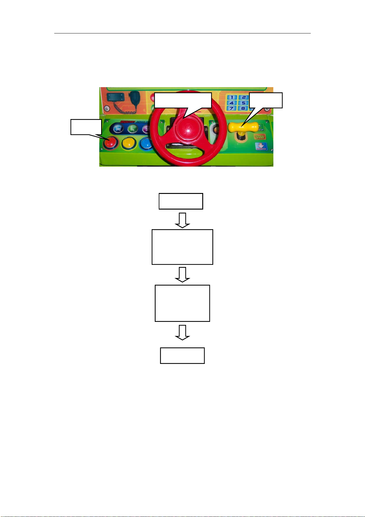
5. HOW TO PLAY
5.1 How To Play
Control the steering wheel during the game play.
Button
5.2 Game Flow
Insert coin
Shifter Steering wheel
Game starts
and ride starts
to move
Press buttons
to have
effects
Game over
10

Rocket School Bus manual
6. GAME SETTINGS
SW1
Item Content SW11 SW12
Coin
per
game
Item Content SW15 SW16 SW17
Fixed
Ticket
1 ON ON
2 off on
3 on off
4 off off
1 on on on
2 off OFF ON
3 on on off
5 off off off
8 on on on
12 off off on
15 on on off
0 OFF OFF OFF
*Note: The above settings are subject to change without notice.
Item Content SW13 SW14
Game
time
(s)
Item Content SW18
Demo
music
30 on on
45 OFF ON
60 on off
90 off off
ON on
OFF OFF
7. ERROR MESSAGE
7.1 Err or Me s sag e
E01: Coin mech error
E03: Settings button error E09: Button 1 error
E04: Test button error
E05: Reset button error E11: Button 3 error
7.2 Trou b l e Sh o oti n gs
Please confirm whether every connector connected tightly.
Troubles Cause Methods
Cannot start
Power cutting
Coin mech. no
reaction
Frame assembly connector fall off
Circuit protector make power SW
Coin mech. signal cable loosen
E08: Initial position detect error E13 Shifter D error
E14 Shifter P error
E10: Button 2 error
Frame assembly fault Please contact with dealer
Please turn on power SW again. If
appeared again and again, machine
in cutting state
Coin mech. fault Change coin mech.
IO control board fault Change IO board
has anomaly. Please contact with
Check coin mech. signal line loosen or
E16 Ticket signal error
Please plug in connector tightly
dealer
not
11

Rocket School Bus manual
8. MAINTENANCE & INSPECTION
8.1 Safety Check
Check the points listed before operating the machine. These checks are necessary for safe
machine operation:
1. Try to run the game before operation each day.
2. Conduct monthly routine checks of game components ensure good working condition
3. Check the machine regularly for dust and clean when necessary.
Note: Parts and components require preventative maintenance to be kept running smoothly
8.2 Handling Precautions
When installing or inspecting the machine, be very careful of the following points and
pay attention to ensure that the player can enjoy the game safely.
Non-compliance with the following points or inappropriate handling running counter to
the cautionary matters herein stated can cause personal injury or damage to the machine
• Before servicing the machine, be sure to turn power off. Servicing without turning the
power off can cause electric shock or short circuit.
• To avoid electric shock or short circuit, do not plug then unplug the power quickly
• Do not expose power cords and earth wires, these are susceptible to damage.
• Damaged cords and wires can cause electric shock or short circuit and should be
replaced immediately.
• When or after installing the product, avoid pulling the power cord to prevent
unnecessary wear and tear. Use the power button to disconnect power.
• In case the power cord is damaged, ask for replacement through where the product was
purchased from or replace locally. Continued usage of damaged cord can cause fire,
electric shock or leakage.
• Perform grounding appropriately. Inappropriate grounding can cause electric shock.
• Use fuses that meet specified rating. Fuses exceeding can cause an electric shock.
• Should a problem occur, turn off the power immediately and stop operating the machine.
Unplug the power cord of the service outlet. Operating the machine without correcting the
problem may cause a fire or injuries.
• Insert the power plug securely into the outlet. Poor contact may cause overheating,
resulting in fire or burns.
• To ensure the warning labels attached on the machine are visible and legible, install the
machine in a well-lit location, and keep the labels clean at all times. Make sure the labels
are not hidden behind other game machines.
WARNING
12

Rocket School Bus manual
9. OVERALL CONSTRUCTION
9.1 Mechanical Part
9.1.1 Main Assembly
No. Part No. Code No Name SPEC./Material Qty
1 R113-314-000 20251301068 Skirt mounted plate C Q235 2
2 R113-101-000 20113010053 C flat washer Q235 28
3 R113-102-000 20101010029 Cross recessed pan head screw Q235 28
4 R113-009-000 29951301013 Protected frame assy. Assembly 1
5 R113-313-000 20251301067 Skirt mounted plate B Q235 2
6 R113-001-000 29951301001 Drive mechanism Assembly 1
7 R113-312-000 20251301066 Skirt mounted plate A Q235 4
8 R113-318-000 20251301071 Protected plastic PVC 2
9 R113-103-000 20101048007 Hexagon flat round head screws Q235 4
10 R113-004-000 29951301A004 Cabinet mechanism Assembly 1
13
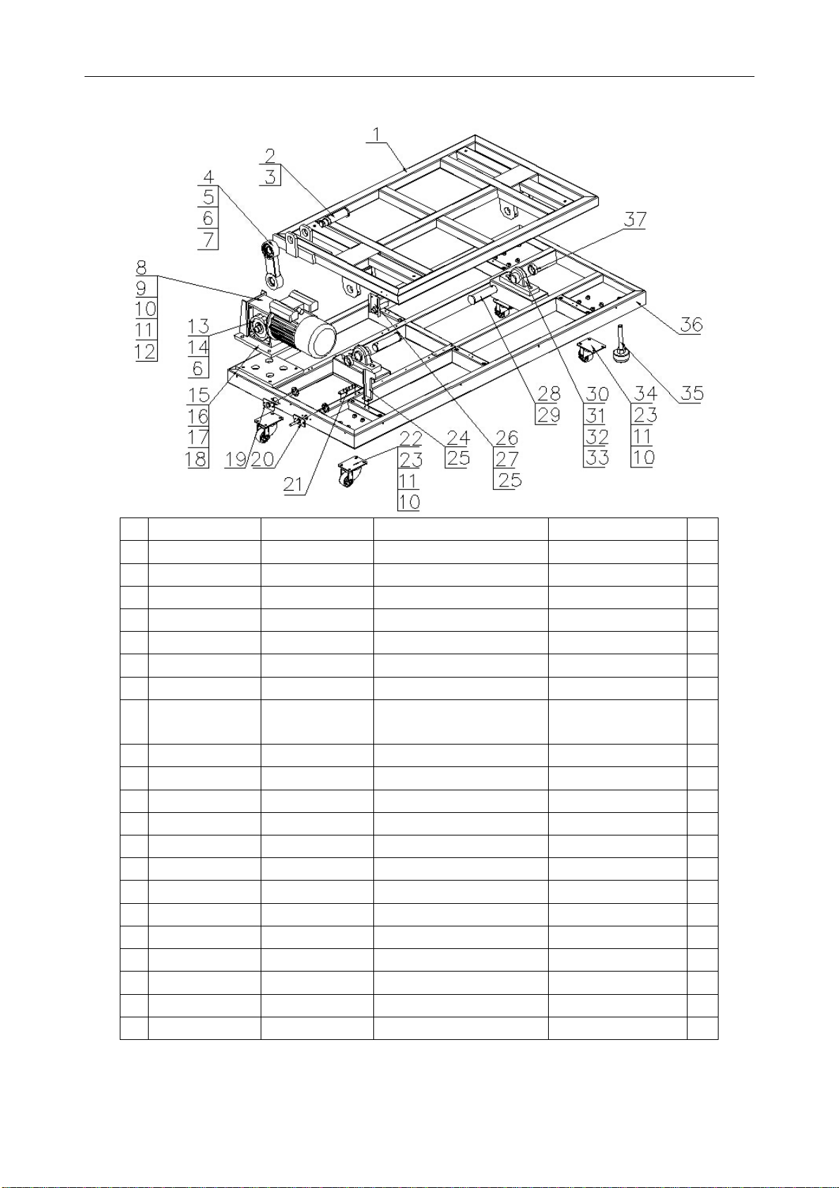
9.1.2 Drive Mechanism
Rocket School Bus manual
No.
Part No. Code No. Name SPEC./Material Qty.
1 R113-003-000 29951301003 Movable frame Assembly. 1
2 R113-237-000 20251301040 Connected rod 45# 1
3 R113-105-000 20105000024 A type circlip for shaft Q235 1
4 R113-228-000 20251301031 Connected part Black 1
5 R113-403-000 20106000057 Deep groove ball BD. 6205zz 2
6 R113-106-000 20105000197 A type circlip for shaft Q235 3
7 R113-107-000 20105000210 A type circlip for hole Q235 2
8 R113-401-000 23405010010 Motor
YL7124-220V
370W 14rev/min
9 R113-108-000 20104040030 Hexagon bolt M8×30 1
10 R113-109-000 20113000005 Standard spring washer 8×2h 24
11 R113-110-000 20113000051 C flat washer 8×1.6h 24
12 R113-111-000 20102000013 Hexagon nut Q235 8
13 R113-229-000 20251301032 Eccentric shaft 40Cr 1
14 R113-402-000 20115080006 General A type flat key Q235 1
15 R113-236-000 20251301039 Motor mounted bracket δ12mm/δ3mm 1
16 R113-112-000 20104000008 Hexagon nut Q235 4
17 R113-113-000 20113000102 Standard spring washer Q235 4
18 R113-114-000 20113000052 C flat washer 4
19 R113-235-000 20251301038 Fuse mounted plate δ2 1
20 R113-234-000 20251301037 Hold cable plate δ2 1
21 R113-233-000 20251301036
GND plate Metal 1
14
1
Rocket School Bus manual
No.
22 R113-406-000 25501000063
Part No. Code No. Name SPEC./Material Qty.
Fixed caster 3-3688-52 2
23 R113-115-000 20104100030 Hexagon bolt Stainless steel 16
24 R113-230-000 20251301033 Reset plate Q235 1
25 R113-104-000 20101000024
Cross recessed pan
head screw
M4×12 4
26 R113-231-000 20251301034 Reset SW bracket Q235 1
27 R113-421-000 21501000004 Sensor
E3F-DS10C4/
NPN-NO
28 R113-226-000 20251301029 Connected shaft φ35x120 2
29 R113-116-000 20107000116 Cotter d5×30 2
30 R113-404-000 20106130158
Spherical surface ball BD.
with seat
NAP206 2
31 R113-117-000 20104031004 Hexagon bolt Q235 4
32 R113-118-000 20113000004 Standard spring washer Q235 4
33 R113-119-000 20113000054 C flat washer Q235 4
34 R113-405-000 25501000062 Movable caster 3-3689-52 2
35 R113-232-000 20251301035 Leveller Q235 2
36 R113-002-000 29951301002 Base frame Assembly 1
37 R113-227-000 20251301030 Shaft sleeve Q235 2
1
15
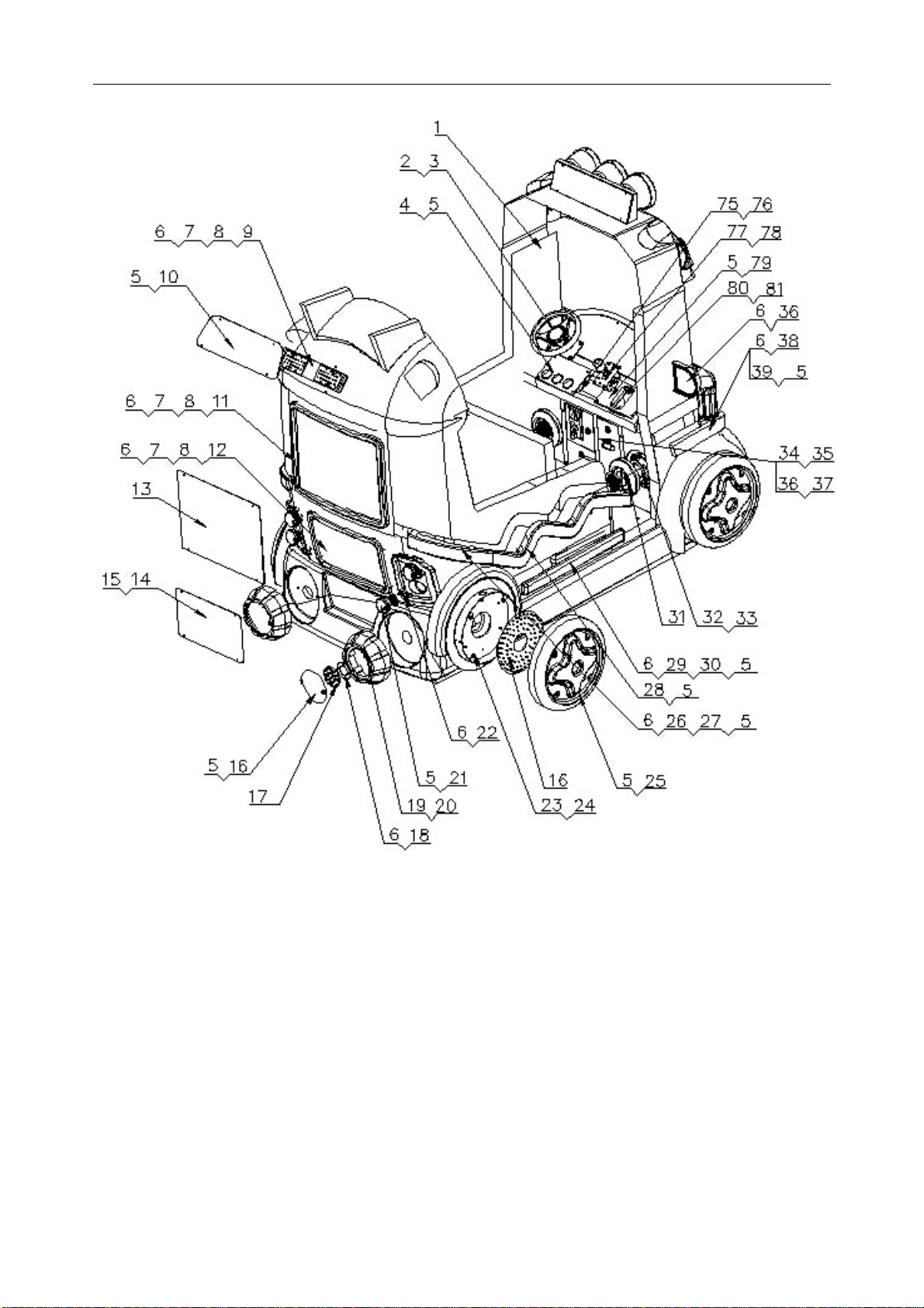
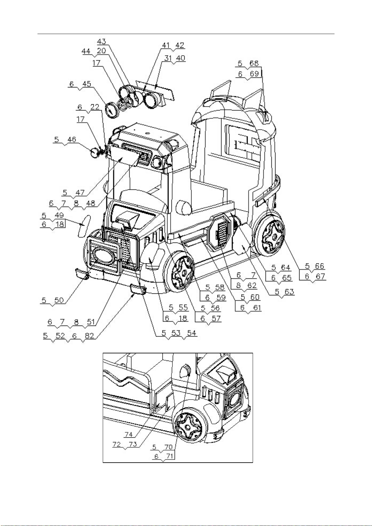
9.1.3 Cabinet Part
Rocket School Bus manual
16
Rocket School Bus manual
17

Rocket School Bus manual
No. Part No. Code No. Name SPEC./Material Qty
1 R113-005-000 29951301005 Cabinet Assembly 1
2 R113-006-000 29951301007 Steering wheel assy. Assembly 1
3 R113-120-000 20101010010
Cross recessed sunk
head screw
Q235 4
4 R113-708-000 20551301B008 Control panel plastic Clear plastic 1
5 R113-121-000 20101000007
6 R113-122-000 20103100009
7 R113-123-000 20101000021
Hexagon flat round
head screws
Cross recessed pan
head self-tapping screw
Cross recessed pan
head screw
M4×20 86
Stainless steel 60
M3×16 36
8 R113-124-000 20102030043 Hexagon nut Q235 36
9 R113-242-000 20651301001 Rear upper light bracket PVC 1
10 R113-704-000 20551301B004 Rear upper light plastic Clear plastic 1
11 R113-243-000 20651301002 Rear big light bracket 1
12 R113-244-000 20651301003 Rear small light bracket 1
13 R113-705-000 20551301005 Rear big light plastic Clear PVC 1
14 R113-310-000 20251301064 Fan mounted plate Q235 1
15 R113-156-000 20101010049
Cross recessed pan
head screw
Q235 4
16 R113-245-000 20651301004 Big taillight cover Red clear plastic 2
17 R113-125-000 20101000101
Cross recessed pan
head screw
Q235 36
18 R113-246-000 20251301044 Big taillight cover bracket Metal 4
19 R113-247-000 20451301002 Big taillight holder Fiberglass 2
20 R113-126-000 20101000052
Cross recessed pan
head screw
10
21 R113-248-000 20651301005 Small taillight cover Yellow clear plastic 2
22 R113-249-000 20251301045 Small taillight cover bracket Metal 6
23 R113-250-000 20251301046 Wheel mounted bracket Q235 4
24 R113-127-000 20103100005
Cross recessed pan
head self-tapping screw
Stainless steel 26
25 R113-251-000 20651301006 Wheel plastic White plastic 1
26 R113-252-000 20651301007 Right side light cover D White plastic 1
27 R113-253-000 20651301008 Light belt mounted plastic PVC 1
28 R113-255-000 20651301010 Right side light cover C White plastic 1
29 R113-256-000 20651301011 Right side light cover B White plastic 1
30 R113-257-000 20651301012 Light belt mounted plastic B PVC 1
31 R113-327-000 26000057001 Speaker light cover Clear PC 4
32 R113-311-000 20251301065 Speaker light bracket Metal 4
18

Rocket School Bus manual
No. Part No. Code No. Name SPEC./Material Qty
33 R113-128-000 20101000025
Cross recessed pan
head screw
M4×16 20
34 R113-326-000 26000056000 Coin door assy. Assembly 1
35 R113-129-000 20104000018 Big step bolt M4×30 8
36 R113-306-000 20251301061 Counter bracket Metal 1
37 R113-130-000 20102030011 Hexagon flange nut Q235 8
38 R113-262-000 20651301013 Right side light cover A White plastic 1
39 R113-263-000 20651301014
Light belt mounted
plastic C
PVC 1
40 R113-264-000 20251301051 Top light bracket cover Q235 1
41 R113-265-000 20251301052 Top light bracket Q235 1
42 R113-131-000 20101108005
Hexagon flat round
head screws
Stainless steel 2
43 R113-266-000 20651301015 Top light bottom cover ABS 3
44 R113-267-000 20251301053 Top light socket Q235 3
45 R113-268-000 20651301016 Top light cover White plastic 3
46 R113-270-000 20651301018 Top side light Red clear plastic 3
47 R113-702-000 20551301B002 Top marquee light Clear plastic 1
48 R113-271-000 20651301019 Top marquee bracket PVC 1
49 R113-272-000 20651301020 L headlight Yellow clear plastic 1
50 R113-701-000 20551301B001 Head decal Clear plastic 1
51 R113-273-000 20651301021 Head light cover bracket PVC 1
52 R113-274-000 20651301022 Head bottom light cover Yellow clear plastic 2
53 R113-275-000 20651301023 Front small light cover White plastic 1
54 R113-276-000 20651301024
Front small light
mounted plate
PVC 1
55 R113-277-000 20651301025 R headlight cover Yellow clear plastic 1
56 R113-278-000 20651301026 Small cooling cover White plastic 6
57 R113-279-000 20651301027 Small cooling light bracket PVC 6
58 R113-280-000 20651301028 L side cover A White plastic 1
59 R113-281-000 20651301029 Light belt mounted plate D PVC 1
60 R113-282-000 20651301030 L side cover B Yellow clear plastic 1
61 R113-283-000 20651301031 Light belt mounted plate E PVC 1
62 R113-284-000 20651301032 L side light bracket PVC 1
63 R113-703-000 20551301B003 Left side light Clear plastic 1
64 R113-285-000 20651301033 L side light cover C White plastic 1
65 R113-286-000 20651301034 Light belt mounted plate F PVC 1
66 R113-287-000 20651301035 L side light cover D White plastic 1
67 R113-288-000 20651301036 Light belt mounted plate G PVC 1
68 R113-289-000 20651301037 Back top light cover White plastic 2
19

Rocket School Bus manual
No. Part No. Code No. Name SPEC./Material Qty
69 R113-290-000 20651301038 Light cover mounted plate PVC 2
70 R113-291-000 20651301039 Rearview mirror cover
71 R113-292-000 20651301040
72 R113-293-000 20251301054 Service door Q235 1
73 R113-294-000 20251301055 Service door frame Q235 1
74 R113-512-000 20351301011 Electric mounted plate Plywood 1
75 R113-299-000 20251301057 Steering wheel reinforced plate Q235 1
76 R113-132-000 20101000010 Cross recessed sunk head screw M5×20 2
77 R113-008-000 29951301010 Shifter assy. Assembly 1
78 R113-133-000 20101000011 Hexagon flat round head screws M5×25 4
79 R113-706-000 20551301B006 Control panel decal B Clear plastic 1
80 R113-304-000 20251301060 Shifter fixed bracket Metal 1
81 R113-134-000 20101010018 Cross recessed sunk head screw Q235 4
82 R113-305-000 20651301044
83 R113-007-000 29951301009
84 R113-131-000 20101108005 Hexagon flat round head screws Stainless steel 2
Rearview mirror light
cover mounted plate
Head bottom light
mounted plate
Meter panel assy. Assembly 1
Yellow
clear plastic
PVC 2
PVC 2
2
20

Rocket School Bus manual
9.1.4 Steering Wheel Part
No. Part No. Code No. Name SPEC./Material Qty
1 R113-135-000 20104001002 Hexagon bolt Q235 1
2 R113-109-000 20113000005 Standard spring washer 8×2h 1
3 R113-110-000 20113000051 C flat washer 8×1.6h 1
4 R113-407-000 41106000020 Steering wheel Red 1
5 R113-239-000 20251301041 Steering wheel shaft Q235 1
6 R113-409-000 20115060003 General A type flat key Q235 2
7 R113-241-000 20251301043 Steering wheel holder Q235 1
8 R113-410-000 20106000064 Deep groove ball BD. 61902 2
9 R113-240-000 20251301042 BD. sleeve Q235 1
10 R113-136-000 20102040002 Non-metallic hexagon lock nut Q235 4
11 R113-137-000 20105010022 A type circlip for shaft do15 black 1
21

9.1.5 Base Protection Part
No. Part No. Code No. Name SPEC./Material Qty
1 R112-305-000 20251301069 Protected frame A φ4 Steel rod 1
2 R112-307-000 20651301046 Protected skirt 1
3 R112-306-000 20251301070 Protected frame B φ4 Steel rod 1
9.1.6 Meter Panel Part
Rocket School Bus manual
No. Part No. Code No. Name SPEC./Material Qty
1 R113-295-000 20451301003
2 R113-296-000 20251301056
3 R113-153-000 20102000010
4 R113-707-000 20551301007
5 R113-154-000 20101108018 Hexagon flat round head screws Stainless steel 6
6 R113-155-000 20101100101 Cross recessed pan head screw Stainless steel 6
7 R113-297-000 20651301041
8 R113-411-000 20251301001
9 R113-412-000 20251301002
10 R113-298-000 20651301042
Meter panel Fiberglass 1
Hexagon bolt Brass 6
hexagon flange nut M3 6
Meter panel plastic Clear plastic 1
Cover plastic Clear plastic 1
Meter needle 1 1
Meter needle 2 1
Display pad Black nylon 1
22
9.2 Mechanical Part
4
5
Rocket School Bus manual
1
2
3
6
7
8
4
No. Part No. Code No. Name SPEC./Material Qty
1 R113-452-000 29751302004
2 R113-447-000 29741003001
3 R113-449-000 29751301004
Top head light
board
Marquee LED
light board
White light LED
board
XYWCQ-LED01.PCB 3
HHXYS-LED02.PCB(V1.0) 4
TJXS-PGLED.PCB(V1.0)
white
2
4 R113-454-000 22002013003 White light belt DC12V 3528LED 60pcs/m 2.1
5 R113-456-000 22002013009 Green light belt DC12V 3528LED 60pcs/m 0.6
6 R113-455-000 22002013004
7 R113-448-000 20740917004 Front light board
8 R113-450-000 29740917004
Blue light belt DC12V 3528LED 60pcs/m 1
LED01-XMJZ.PCB(V1.0) 2
Bottom LED
board
HHXYS-LED01.PCB(V1.0) 2
23

Rocket School Bus manual
4
2
1
3
5 6
No. Part No. Code No. Name SPEC./Material Qty
1 R113-447-000 29741003001
2 R113-455-000 22002013004
3 R113-454-000 22002013003 White light belt
4 R113-457-000 22702010025
5 R113-449-000 29751301004
6 R113-450-000 29740917004
Marquee LED
light board
Blue light belt
DC fan
White light LED
board
Bottom LED
board
HHXYS-LED02.PCB(V1.0) 4
DC12V 3528LED
60pcs/m
DC12V 3528LED
60pcs/m
XW-1238M12S DC12V
0.4A
1
1
1
TJXS-PGLED.PCB(V1.0) 4
HHXYS-LED01.PCB(V1.0) 2
24

Rocket School Bus manual
6
1
7
4
2
3
4 5
9
8
10
11
6, 7
No. Part No. Code No. Name SPEC./Material Qty
1 R113-453-000 22002013002
2 R113-455-000 22002013004
3 R113-451-000 29751301005
4 R113-454-000 22002013003 White light belt DC12V 3528LED 60pcs/m
5 R112-449-000 29740917007
6 R113-444-000 29751301003
7 R113-445-000 22801000047
8 R113-430-000 22401210001
9 R113-433-000 22404020014
10 R113-434-000 22301000001
11 R113-435-000 23100000006 Ticket dispenser
RGB light belt
Blue light belt DC12V 3528LED 60pcs/m
Blue LED light
board
White light pcb
board
Speaker light
board
Speaker 4”, 8Ω, 15W 2
Button middle size(blue)37 3
Shifter BL (round head) 1
Coin mech Comparator 1
DC12V 5050LED 3 color
LED
BBGS-A2.PCB(V1.0) blue 4
LED01-XMJZ.PCB(V1.0) 1
LED-SP.PCB(V1.0) 2
CL-022Q-386 1
2
25
2
Rocket School Bus manual
4
1
3
5
9
10
6
7 8
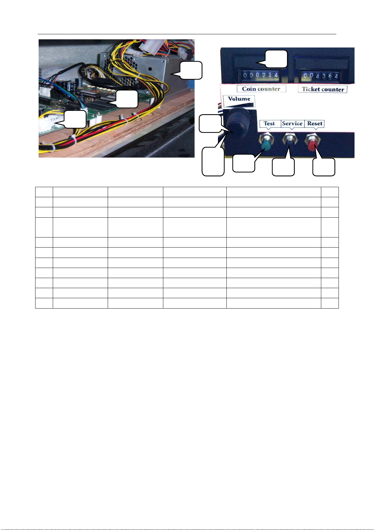
No. Part No. Code No. Name SPEC./Material Qty
1 R113-424-000 21602000001
2 R113-427-000 21702000012
3 R113-460-000 21701000029 M3 main board
4 R113-437-000 23000000006
5 R113-443-000 22403000001
6 R113-439-000 22402030002
7 R113-440-000 22402050001
8 R113-438-000 22402010002
9 R113-441-000 21709000002
10 R113-442-000 22501000006
Power supply BTX-3039(110V220V) 1
Music board SY-MUSIC01 PCB(1.1) 1
M3_MB.PCB
150×200×2.0mm
Counter C-012 12VDC 18CPS 2
POT knob Black 1
Green button PB:11C02R 1
Black button PB:11C02R 1
Red button PB:11C02R 1
POT pcb. VR.PCB 1
POT 10K 1
1
26

9.3 Decal Part
Rocket School Bus manual
No. Part No. Draw No. Name SPEC./Material Qty
1 R113-712-000 20551301012
2 R113-702-000 20551301B002
3 R113-715-000 20551301B014
4 R113-704-000 20551301B004 Rear upper light plastic
5 R113-705-000 20551301005
6 R113-703-000 20551301B003
7 R113-701-000 20551301B001
8 R113-710-000 20551301B010
9 R113-711-000 20551301011
10 R113-709-000 20551301009
11 R113-708-000 20551301B008
12 R113-721-000 20551301B025
13 R113-722-000 20551301B026
14 R113-723-000 20551301B027
15 R113-706-000 20551301B006 Control panel decal B Clear plastic 1
16 R113-716-000 20551301A015 Meter panel right sticker PVC100u sticker 1
17 R113-707-000 20551301007
18 R113-714-000 20551301A014 Meter panel left sticker PVC100u sticker 1
19 R113-713-000 20551301013
Top light decal PVC100u sticker 2
Top marquee light Clear plastic 1
Seat back decal PVC100u sticker 1
Clear plastic 1
Rear big light plastic Clear PVC 1
Left side light Clear plastic 1
Head decal Clear plastic 1
Front logo sticker PVC100u sticker 1
Front window sticker PVC100u sticker 1
Back fan sticker PVC100u sticker 1
Control panel plastic Clear plastic 1
Button 1 sticker PVC100u sticker 1
Button 2 sticker PVC100u sticker 1
Button 3 sticker PVC100u sticker 1
Meter panel plastic Clear plastic 1
Tail top light sticker PVC100u sticker 1
27

Rocket School Bus manual
No. Part No. Draw No. Name SPEC./Material Qty
1 R113-717-000 20551301B019
2 R113-718-000 20551301B020
3 R113-719-000 20551301B021
4 R113-720-000 20551301B022
5 R113-732-000 25600000077
6 R113-733-000 25600000091
7 R113-730-000 25600000071
8 R113-731-000 25600000072
9 R113-727-000 25600000037
10 R113-726-000 25600000036
11 R113-725-000 25600000034
12 R113-724-000 25600000100
13 R113-735-000 25600000096 Service contact label S PVC100u sticker 1
14 R113-734-000 25600000095 Service contact label L PVC100u sticker 1
15 R113-729-000 25600000067
Uncertified 110V
nameplate
Uncertified 220V
nameplate
CE nameplate 1mmPVC 1
TUV nameplate 1mmPVC 1
Fuse label PVC100u sticker 1
GND label PVC100u sticker 1
110V label PVC100u sticker 1
25600000072 PVC100u sticker 1
Warning label L PVC100u sticker 2
Warning label S PVC100u sticker 3
Ticket label PVC100u sticker 1
Counter label PVC100u sticker 1
Warning label PVC100u sticker 1
1mmPVC 1
1mmPVC 1
28

Wiring Diagram
5
123456789
Wire Color Wire Type Tolerance
Brown
Red
Oran ge
ABCDEFGHI
1 2 3 4 5 6 78
Light Green
Black
Pi nk
JKLMNOP
AW G30 UL1007
AW G28 UL1007
AW G26 UL1007
A
Yel l o w
Green
Shielding lay e r
Lig ht Bl ue
AW G24 UL1007
AW G22 UL1007
Notice:
Blue
Vi ol e t
Gray
White
The color and the type of the wire express as follow. For example: 2 0 M
Wire type: M is A WG24 UL10 07
Wire color :20 is single red
R
Q
AW G20 UL1007
AW G18 UL1007
AW G16 UL1005
AW G14 UL1005
KLXB-PX-13
0~1000
±10
UnitemmProp.
1001~200 0
2001~300 0
3001~400 0
4001~500 0
:
±20
±30
±40
±50
To s h i f t e r
To c o u n t er
18
19
18
19
CP
A0P
A0P
KLXB-PX-09
R Chan nel
UNIS
Amusement m achine
Unive rsal Sp ace
R+
R-
CN5
1
2
1
2
VH
95
90
Drawing
Coll at e
Design
Check
C
22
Technics
Approve
Standard
Path:
D:\
飞秋自动 接收文 件
\
李启耀
(199.199 .12.111 )\2014- 12-18 13_
Name:
Cha rt Dra wing NO.
Date:
Rocket School Bus (monitor ver.) Wiring Diagram 1
A3
27-Dec-201 4
KLXBP-PX-00-01
Page
Ve rsion:
V1.0
A
R Chan nel
GND
GND
6
3
4115116
VH
E
A0M
60M
20M
90M
E
171819
20
21
E
60M
A0M
XH
5
10K POT
Bass adjus tment
Rocket School Bus manual
B
GND plate 2
90Q
VLR VLP
8
8
To coin mech
A0P
L Channel
50M
50M
34651
34162
VR.PCB
To tick et di spens er
AC IN
11 11
101617
66
101617
40PX2
40PX2
A0P
A0P
R
W
Audio inpu t L
Audio input R
L Channel
CN3
12345
1102
20M
40M
50M
97M
10111213141516
20M
40M
2
J1
Speaker
B
90P
30M
40M
CP
2
2
KLXBP-PX-05
90Q
90Q
VLR VLP
8
8
60Q
60Q
A0P
50P
P1
347
347
A0P
A0
VH
L-
2
2
VH
70
10M
40
70
J14
1
1
40
70
+
-
KLXBP-PX-06
P2
P
44
123
123
C
24X2
A0X2
24X2
A0X2
24
VH
44
CN1
CN4
CP
2
2
12V
GND
AD0
3.3V
J3
123
123
XH
RA
20M
90M
E
E
40P
A0P94959697
C
J09
24
123456789
24
P
E
80M24A0
40
70
J13
CP
1
123
1
123
40
70
+
-
CP
123
123
I nit i al pos it io n dete ct
12V1GND
L+
1
1
40
TO XBPM-PX-0 0- 02
前控台引线
Speaker
KLXB-PX-12
50Q
A0Q
A0Q
A0Q
10Q
10Q
60QX2+90P
LOAD N
LOAD L
24A024
GND
12V
Ti ck et s i gnal
97M
60M4070
A0M
60M
A0M
CP
J12
1060A0
3X24AWG flexible cable
J15
106090
HW1
50P
KLXB-PX-02
Main Montor
A0P
KLXB-PX-01
Power plu g
KLXBP-PX-27
M3 main board
J22
1231425
2345678
D
Side chasi ng li ght1
Side chasi ng li ght2
Side chasi ng li ght3
Flash LED 1
Flash LED 2
Flash LED 3
Lit & flash
Fl ash
1010
8
8
99
VH
J21
1234567
1234567
10X27020X2
30X2
40X2
50X26080
C
45R
50Q
J03
90P
KLXB-PX-04
11
VLR-01VVLP-01V
A0Q
45R
90Q
J04
1234567
1234567
A0Q
45R
90Q
45R
J05
1234567
1234567
10Q
45R
60Q
45R
10QX2+A0P
45RX2
10Q
60Q
LINE N
A0
123
123
GND
Shi fter P
95M
10Q
AC DC
LINE L
LINE E
Solid state reply
YE20T4L2 20A
Filter
-
KLXBP-PX-08
98
J1
Initia l posit ion detect
But ton 1
But ton 3
Shi fter D
But ton 2
10111213141516
9
10111213141516
9
80M
90M
91M
92M
94M
GND pl at e 1
A0Q
45R
90Q
VLR
123
J53
123
VLP
A0P
50P
90P
10Q
SSR-40DA
+
Servi ce bu tt o n
Reset b u tt on
45678
45678
50M
Audio port
12V
24
P
J66
1
2
1
2
C
24
A0
Ti ck e t co u n t
Motor drive
Tes t bu t t o n
40M
Coi n coun t
Coi n
J20
123
8
123
8
99
VH
10M
30M
F1/10A/250 V
KLXB-PX-03
VLP-02V
1
2
J02
VLR-02V
1
2
A0Q
A0P
50P
90P
50Q
50Q
VLR-03V
50PA0P
A0Q
90Q
123
J01
123
VLP-03V
10Q
60Q
45Q
M
90P
AC IN
HDMI port
DVI port
Bu tt o n ligh t 1
Bu tt o n ligh t 2
Bu tt o n ligh t 3
Ti ck e t dr i v e
Ti ck e t li gh t
Si de li g ht R
Si de li g ht B
Si de li g ht G
+12 V
J23
10
1234567
1234567
249192939495969798
61728
99
VH
96X2
97X2
98X2
KLXBP-PX-07
20M
40M
50M
17
18
1920212223
1920212223
20M
40M
50M
40X2
70X2
80M
10111213141516
101112131415161718
90M
91M
92M
94M
95M
80M
J08
123456789
123456789
24X3
A0X4
919293
50
95
90
969798
10
C
11
12
Back fiberglass light
TO XBPM-PX-00 -0 2
969798
40P
A0P10203040
1011121314
C
J07
123456789
TO XBPM-PX-00 -0 2
40P
A0P1020304050607080
J06
123456789
Front fiberglass Light
40P
A0P
919293
90M
91M
92M
94M
95M
KLXBP-PX-09
94M
95M
A0
456
123
J11
456
123
40M
50M
20M
30M
A0
Shifter
93
92M
button 3
90M
91M
92M91929324
A0
CP
8
8
90M
91M
92M91929324X3
A0X3
A0A091
92
91M
Light
Butt on l ight3
Button2
C
2424A0
90M
Light
Butt on l ight2
Button 1
KLXB-PX-10
J10
1234567
1234567
24
Light
button light 1
D
7654321
8
29

8
7654321
0.2M
Back t op lef t si de light
LED3528 b lue li ght bel t
GND
12V
1
2
1
2
CP
J41
242024
20X6
A0X6
24X17
cabl e cap
40P
A0P
10X22030X2
123456789
J07
Rocket School Bus manual
Coin mech
123
123
9495969710M
A0X5
KLXB-PX-23
24A010M
44
XH
PC
6
6
Front contorl panel cable
B
Ticket dispense r
J1
123
123
97M24A09524
30M
40M
50M
97M
10111213141516
TO XBPM-PX-00-02
A
V1.0
KLXBP-PX-00-02
27-Dec-2014
Rocke t School Bus (Monitor Ver.) Wiri ng Diagram 2
Date:
Name:
Version:
Univer sal Space
Amusement machin e
UNIS
XBPM-PX-26
KLXB-PX-25
KLXB-PX-24
Coin counter
20M
A0M
LEDR1 1K
20MX2
1
2
1
2
44
CP
J50
J51
VH
94
20M
171819
Ticket count er
20M
A0M
GND
A0MX3
A0
A0M
A0M
1234567
1234567
969724A030M
90M
E
20
21
22
P
S1S2S3
Tes t b u tt o n
30M
123
20M
90M
E
Service button
Reset b utt on
40M
50M
20M
90M
E
8
123
8
123
CP
J52
CP
40M
50M
20M
90M
E
KLXBP-PX-22
D
KLXB-PX-21
0.4M
0.4M
Back mi ddle li ght ( middle LOGO)
Back top middle light ( top LOGO)
0.2M
LED3528 b lue li ght bel t
12V
1
1
J42
20
40X2
Back fiberglass light
GND
12V
12V
GND
LED3528 whit e li ght b elt
LED3528 whit e li ght b elt
HHXYS-LED02.PCB white
J1
1
2
2
1
12V
Back t op ri ght s ide light
J2
GND
J1
2
2
CP
24
50X2
TO KLXB-PX-00-02
12V
XH
GND
GND
0.4M
0.4M
Back middle left side light (up)
Back middle left side light (bottom)
Back middle right side light (up)
2
2
XH
302440
2
J39
214
50
24
30X4
24
1
2
1
2
J1
TJXS-PGLED.PCB white
J1
1
2
2
1
XH
50
CP
341
3
40
30
40X4
50X4
3040503040503040503040
XH
123456789
123456789
J2
Rear right si de wheel light
Back middle right side light (bottom)
TJXS-PGLED.PCB white
J1
1
2
2
1
BBGS-A2.PC B
XH
1
2
1
2
12V
HHXYS-LED02.PCB White
1
2
1
1
2
1
J43
XH
A0
24
A0
989796
95X2
90X2
P
12
11
10
Back mi ddle light( bottom LOGO)
GND
12V
GND
LED3528 whit e li ght b elt
LED3528 whit e li ght b elt
TJXS-PGLED.PCB white
LED01-XMJZ.PC B White
PC
J1
2
2
1
1
2
2
1
1
CP
J44
24A02410242024102420242024
A0
24
302440
50
CP
341
2
J38
214
3
30
24
40
50
30X4
40X4
50X4
3040503040503040503040
24
XH
1
2
123456789
1
2
123456789
J1
J2
BBGS-A2.PC B
TJXS-PGLED.PCB white
J1
J1
1
2
1
2
2
2
1
1
XH
VH
KLXB-PX-20
50
XH
101112
101112
Rear left side wheel light
C
Back r i ght speaker light
Back left speaker light
Back left speaker
Back bottom left side light ( stoplight)
Back bottom right side light (stoplight)
+
-
HHXYS-LED01.PCB white
HHXYS-LED01.PCB red
1
1
101112
101112
40
J1
1
2
1
2
2
2
1
1
J45
XH
XH
95
20
989724
96
214
3
J40
341
2
PC
989724
96
B
R
G
12V
50
XH
5050 3 col or l ight belt
Back l eft c hasing ligh
0.5M
J1
XH
Back right speaker
Fan
CP
J1
FAN
12V/4"
24A010M
A020A0
PC
2
1
12345
12345
2
1
J52
J49
24A010M24A0
A0
24
24X5
123456789
J09
+
-
LED-SP.PCB(V1.0)
LED-SP.PCB(V1.0)
J1
J1
1
1
70
A0
24
123
2
123
2
J46
CP
90
24
A0
2
1
2
2
1
2
XH
XH
40
70
24
123
1
2
123
1
2
CP
J48
CP
J47
95
90
24
A0
KLXB-PX-14
Cable cap
D
KLXB-PX-17
XYWCQ-LED01. PCB blu e
J1
1
2
1
2
XH
2460708024
24X36070
80
123
4
123
4
J25
246070
80
20X4
10X4
A0X9
24X30
40P1020
A0P
123456789
J06
Front top light
XYWCQ-LED01. PCB blu e
J1
1
2
1
2
CP
30X2
40X2
50X2607080969798
Front fiberglass light
XH
TO XBPM-PX-00-02
XYWCQ-LED01. PCB blu e
J1
1
2
1
2
24
96X4
1011121314
96249798962497
98
R
B
R
B
G
G
12V
12V
0.1M
KLXB-PX-18
0.1M
0.05M
Front top right side light
TJXS-PGLED. PCB whit e
J1
1
1
24
20
BBGS-A2.PCB
LED3528 whit e li ght b elt
GND
12V
2
1
2
1
2
2
J26
XH
2410241024
KLXB-PX-15
Front middle lef t side l ight (rear view mirro r)
CP
101112
101112
0.05M
Front m id dle rig ht s i de light (rear v iew mirr or)
LED3528 whit e li ght b elt
LED3528 blu e li ght bel t
Front m id dle li ght ( TURBO)
Front middle lig h t( bottomLOGO)
GND
12V
GND
12V
LED01-XMJZ.PCB w hite
J1
1
2
1
2
A0
302440
2
214
30
24
30X4
24
1
2
1
2
1
2
1
2
CP
24
A0
50
CP
341
3
40
50
40X4
50X4
3040503040503040503040
XH
123456789
123456789
J2
Front w heel light R
J1
VH
24
KLXB-PX-16
BBGS-A2.PCB
1
2
1
2
CP
J27
J28
J17
50
XH
J1
C
Front top middle light (LOGO)
HHXYS-LED02.PCB white
J1
1
2
2
1
XH
Front top left side light
XH
1
2
1
2
J2
XH
TJXS-PGLED. PCB whit e
HHXYS-L ED 0 2. PC B whi te
J1
J1
1
2
1
2
1
1
2
2
XH
XH
24
A0
24
20
98X4
97X4
302440
50
CP
341
2
P
J16
214
3
50
24
40
30
30X4
40X4
50X4
3040503040503040503040
24
XH
1
2
123456789
1
2
123456789
J1
J2
Front w heel light L
Front middle left side light
0.1M
0.1M
LED3528 gree n li ght bel t
LED3528 gree n li ght bel t
GND112V
GND
12V
LED01-XMJZ.PCB w hite
24A024A024A024A024A024
1
2
1
2
1
A0
2
2
1
2
1
2
CP
J29
CP
J30
101112
101112
2430405024
50
XH
24A024
1
2
J18
1
2
24A024
12V
GND
Middle lef t bot tom li ght
LED3528 whit e light belt
0.15M
J31
24
A0
C
1
J19
1
P
A0
12V
LED 3528 blue ligh t b elt
0.5M
VH
LED3528 gree n li ght bel t
12V
1
1
2
2
GND
Middle right bot tom l igh t
0.1M
GND
2
2
CP
24A024
C
J20
P
24A024
J1
J32
1
2
1233
1
2
1
2
LED-SP.PCB(V1.0)
Fron t l ef t sp eaker li ght
0.1M
LED3528 gree n li ght bel t
GND
12V
1
2
1
2
2430405024
CP
XH
CP
J21
J1
LED3528 gree n li ght bel t
12V
1
1
J33
A0
1
2
1233
A0
1
2
1
2
LED-SP.PCB(V1.0)
Front r ight s peak er ligh t
Front middle right side light
0.1M
0.1M
LED3528 gree n li ght bel t
Front bottom left side light (head light)
GND
GND
12V
HHXYS-L ED 0 1. PC B whi te
A0
J1
J1
1
2
2
1
2
1
2
1
2
2
CP
CP
J34
XH
24
20
24
962497
98
24
A0
CP
XH
CP
VH
1
2
341
2
J22
J23
1
2
214
3
J1
962497
98
R
B
G
12V
LED01-XMJZ.PC B white
5050 3 c olor l ight belt
Middle left side STOP light
Middle lef t c hang ing colo r light
0.1M
B
0.1M
R
B
R
B
G
G
12V
12V
962497
98
962497
98
R
B
R
B
G
G
12V
LED3528 whit e li ght b elt
LED3528 whit e li ght b elt
Front bot to m l ef t side lig ht (f oglig ht)
12V
Front bot to m ri ght sid e li ght (f ogl i ght)
Front bottom right side light (head light)
R
B
R
B
G
GND
12V
GND
12V
HHXYS-L ED 0 1. PC B whi te
1
2
1
2
1
2
1
2
1
2
1
2
CP
J35
CP
J36
XH
24
10
24
10
24
20
962497
98
962497
98
CP
CP
341
2
341
2
J24
214
3
214
3
962497
98
962497
98
R
B
R
B
G
G
12V
12V
5050 3 c olor l ight belt
5050 3 c olor l ight belt
Front lef t c hanging color li ght
Front r ight c hang ing colo r light
0.4M
0.25M
G
12V
12V
5050 3 c olor l ight belt 0.05M 5050 3 color light belt 0. 25M5050 3 col or l ight belt 0.65M
5050 3 c olor l ight belt 0.15M 5050 3 c olor l ight belt 0.05M
962497
98
962497
98
123
4
R
B
123
4
G
J37
CP
12V
962497
98
±10
±20
±30
±40
±50
:
5050 3 c olor l ight belt
Middle right cha ngi ng color l igh t
KLXB-PX-19
Exampl e 2 0 m
AWG14 UL1015
Col or of the wir e: 2 0 means red
Size of the wire: m means AW G24 UL 101 5
whi te
Note: Wire col or and wire s ize is shown in co de.
A
Tolerance
0~1000
1001~2000
2001~3000
3001~4000
4001~5000
unit mm
scale
AWG30 UL1015
AWG28 UL1015
AWG26 UL1015
AWG24 UL1015
AWG22 UL1015
AWG20 UL1015
AWG18 UL1015
AWG16 UL1015
jkLmnopqr
Wire size code
AWG30 UL1007
AWG28 UL1007
AWG26 UL1007
AWG24 UL1007
AWG22 UL1007
AWG20 UL1007
AWG18 UL1007
AWG16 UL1007
JKLMNOP
Q
Wire size code
1 2 3 4 5 6 78
black
pink
light green
sky blue
shield layer
ABCDEFGHI
brown
red
orange
yel l ow
green
blue
vi ol et
grey
123456789
Wire color code
30

Have Questions? Contact us!
www.universal-space.com
International Support Center USA Support Center
Tel: +1-905-477-2823
Fax: +1-905-477-2660
Email: service@universal-space.com
(Contact: Clement Yau)
Email:tsnelling@unisusasupportcenter.com
Tel: 972-241-4263
Fax: 214-919-4918
(Contact: Tim Snelling)
 Loading...