

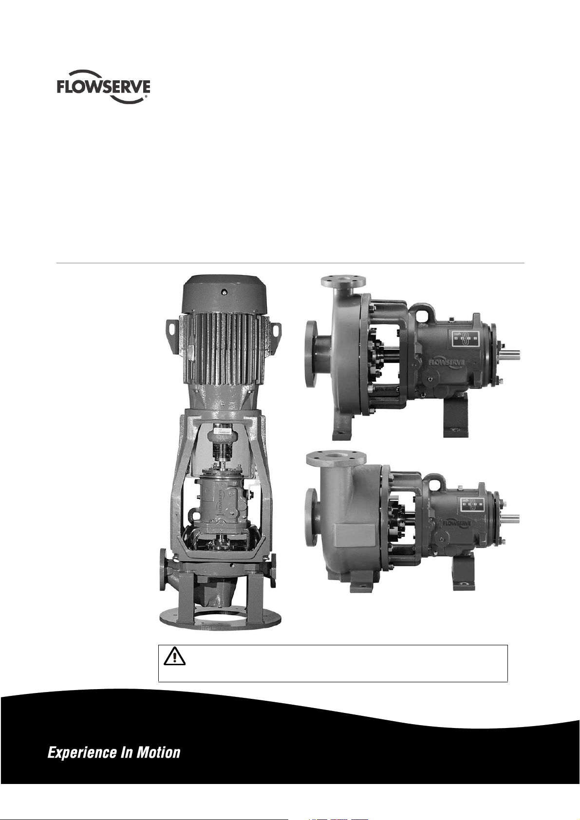
UNIREX Pump User Manual
USER INSTRUCTIONS
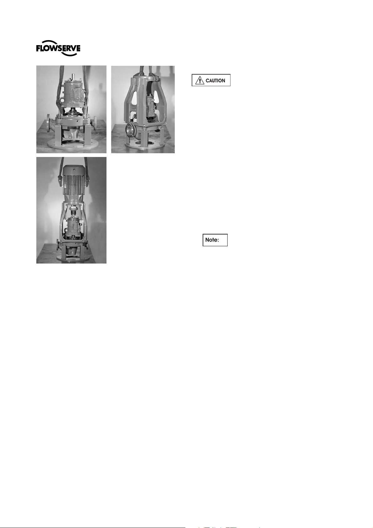
Durco Mark 3 sealed metallic pumps
Installation
Operation
Mark 3 Standard, In-Line, Lo-Flo, Recessed Impeller,
Unitized Self-Priming and Sealmatic pumps
PCN=71569102 08-06 (E) (incorporating P-10-502-E)
Maintenance
These instructions must be read prior to installing,
operating, using and maintaining this equipment.

MARK 3 USER INSTRUCTIONS ENGLISH 71569102 08-06
CONTENTS
Page
CONTENTS ............................................................ 2
1 INTRODUCTION AND SAFETY .......................... 3
1.1 General......................................................... 3
1.2 CE marking and approvals ............................ 3
1.3 Disclaimer..................................................... 3
1.4 Copyright ...................................................... 3
1.5 Duty conditions ............................................. 3
1.6 Safety ........................................................... 4
1.7 Name plate and safety labels ........................ 7
1.8 Noise level .................................................... 8
2 TRANSPORT AND STORAGE............................ 9
2.1 Consignment receipt and unpacking.............. 9
2.2 Handling ....................................................... 9
2.3 Lifting............................................................ 9
2.4 Storage....................................................... 10
2.5 Recycling and end of product life..................11
3 DESCRIPTION.................................................. 11
3.1 Configurations..............................................11
3.2 Nomenclature ..............................................11
3.3 Design of major parts .................................. 12
3.4 Performance and operation limits ................ 12
4 INSTALLATION................................................. 18
4.1 Location...................................................... 18
4.2 Part assemblies .......................................... 18
4.3 Foundation.................................................. 18
4.4 Grouting...................................................... 20
4.5 Initial alignment........................................... 21
4.6 Piping ......................................................... 22
4.7 Electrical connections ................................. 31
4.8 Final shaft alignment check ......................... 32
4.9 Protection systems...................................... 32
5 COMMISSIONING, STARTUP, OPERATION
AND SHUTDOWN............................................ 33
5.1 Pre-commissioning procedure ..................... 33
5.2 Pump lubricants .......................................... 33
5.3 Impeller clearance....................................... 36
5.4 Direction of rotation..................................... 36
5.5 Guarding..................................................... 36
5.6 Priming and auxiliary supplies ..................... 37
5.7 Starting the pump........................................ 38
5.8 Running or operation................................... 38
5.9 Stopping and shutdown............................... 39
5.10 Hydraulic, mechanical and electrical duty .. 39
6 MAINTENANCE................................................. 39
6.1 Maintenance schedule................................. 40
6.2 Spare parts.................................................. 40
6.3 Recommended spares and
consumable items....................................... 41
6.4 Tools required.............................................. 41
6.5 Fastener torques ......................................... 41
6.6 Setting impeller clearance and impeller
replacement................................................ 42
6.7 Disassembly................................................ 44
6.8 Examination of parts.................................... 47
6.9 Assembly of pump and seal......................... 50
7 FAULTS; CAUSES AND REMEDIES ................. 57
8 PARTS LIST AND DRAWINGS.......................... 59
8.1 Standard Mark 3 pump, Group 1.................. 59
8.2 Standard Mark 3 pump,
Group 2 and Group 3 ................................... 60
8.3 Mark 3 Sealmatic pump, Group 2 ................ 61
8.4 Mark 3 Lo-Flo, Group 2................................ 61
8.5 Mark 3 Unitized Self Priming pump,
Group 2 ....................................................... 62
8.6 Mark 3 Recessed Impeller pump, Group 2...62
8.7 Mark 3 In-Line pump, Group 1 ..................... 63
8.8 Mark 3 In-Line pump, Group 2 ..................... 64
8.9 Mark 3 C-Face Adapter,
Group 1 and Group 2 ................................... 65
8.10 General arrangement drawing ................... 65
9 CERTIFICATION ............................................... 66
10 OTHER RELEVANT DOCUMENTATION
AND MANUALS............................................... 66
10.1 Supplementary User Instructions ............... 66
10.2 Change notes............................................ 66
10.3 Additional sources of information ............... 66
Page
Page 2 of 68 flowserve.com
MARK 3 USER INSTRUCTIONS ENGLISH 71569102 08-06
1 INTRODUCTION AND SAFETY
1.1 General
These instructions must always be kept
close to the product’s operating location or
directly with the product.
Flowserve products are designed, developed and
manufactured with state-of-the-art technologies in
modern facilities. The unit is produced with great
care and commitment to continuous quality control,
utilizing sophisticated quality techniques, and safety
requirements.
Flowserve is committed to continuous quality
improvement and being at your service for any further
information about the product in its installation and
operation or about its support products, repair and
diagnostic services.
These instructions are intended to facilitate
familiarization with the product and its permitted use.
Operating the product in compliance with these
instructions is important to help ensure reliability in
service and avoid risks. The instructions may not
take into account local regulations; ensure such
regulations are observed by all, including those
installing the product. Always coordinate repair
activity with operations personnel, and follow all plant
safety requirements and applicable safety and health
laws/regulations.
These instructions must be read prior to
installing, operating, using and maintaining the
equipment in any region worldwide. The
equipment must not be put into service until all
the conditions relating to safety noted in the
instructions, have been met.
1.2 CE marking and approvals
It is a legal requirement that machinery and equipment
put into service within certain regions of the world shall
conform with the applicable CE Marking Directives
covering Machinery and, where applicable, Low Voltage
Equipment, Electromagnetic Compatibility (EMC),
Pressure Equipment Directive (PED) and Equipment for
Potentially Explosive Atmospheres (ATEX).
Where applicable, the Directives and any additional
Approvals, cover important safety aspects relating to
machinery and equipment and the satisfactory provision
of technical documents and safety instructions. Where
applicable this document incorporates information
relevant to these Directives and Approvals.
To confirm the Approvals applying and if the product is
CE marked, check the serial number plate markings
and the Certification. (See section 9, Certification.)
1.3 Disclaimer
Information in these User Instructions is believed
to be reliable. In spite of all the efforts of
Flowserve Pump Division to provide sound and all
necessary information the content of this manual
may appear insufficient and is not guaranteed by
Flowserve as to its completeness or accuracy.
Flowserve manufactures products to exacting
International Quality Management System Standards
as certified and audited by external Quality
Assurance organizations. Genuine parts and
accessories have been designed, tested and
incorporated into the products to help ensure their
continued product quality and performance in use.
As Flowserve cannot test parts and accessories
sourced from other vendors the incorrect
incorporation of such parts and accessories may
adversely affect the performance and safety features
of the products. The failure to properly select, install
or use authorized Flowserve parts and accessories is
considered to be misuse. Damage or failure caused
by misuse is not covered by the Flowserve warranty.
In addition, any modification of Flowserve products or
removal of original components may impair the safety
of these products in their use.
1.4 Copyright
All rights reserved. No part of these instructions may
be reproduced, stored in a retrieval system or
transmitted in any form or by any means without prior
permission of Flowserve Pump Division.
1.5 Duty conditions
This product has been selected to meet the
specifications of your purchaser order. The
acknowledgement of these conditions has been sent
separately to the Purchaser. A copy should be kept
with these instructions.
The product must not be operated beyond
the parameters specified for the application. If
there is any doubt as to the suitability of the
product for the application intended, contact
Flowserve for advice, quoting the serial number.
If the conditions of service on your purchase order are
going to be changed (for example liquid pumped,
temperature or duty) it is requested that the user seeks
the written agreement of Flowserve before start up.
Page 3 of 68 flowserve.com
MARK 3 USER INSTRUCTIONS ENGLISH 71569102 08-06
1.6 Safety
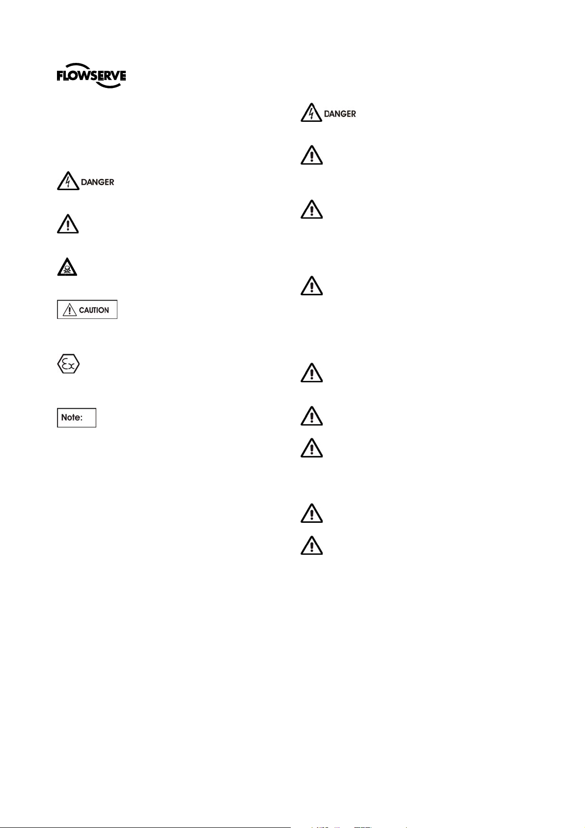
1.6.1 Summary of safety markings
These User Instructions contain specific safety
markings where non-observance of an instruction would
cause hazards. The specific safety markings are:
This symbol indicates electrical safety
instructions where non-compliance will involve a high
risk to personal safety or the loss of life.
This symbol indicates safety instructions where
non-compliance would affect personal safety and
could result in loss of life.
This symbol indicates “hazardous and toxic fluid”
safety instructions where non-compliance would affect
personal safety and could result in loss of life.
This symbol indicates safety
instructions where non-compliance will involve some
risk to safe operation and personal safety and would
damage the equipment or property.
This symbol indicates explosive atmosphere
zone marking according to ATEX. It is used in safety
instructions where non-compliance in the hazardous
area would cause the risk of an explosion.
NEVER DO MAINTENANCE WORK
WHEN THE UNIT IS CONNECTED TO POWER
(Lock out.)
DRAIN THE PUMP AND ISOLATE PIPEWORK
BEFORE DISMANTLING THE PUMP
The appropriate safety precautions should be taken
where the pumped liquids are hazardous.
FLUOROELASTOMERS (When fitted.)
When a pump has experienced temperatures over
250 ºC (482 ºF), partial decomposition of
fluoroelastomers (example: Viton) will occur. In this
condition these are extremely dangerous and skin
contact must be avoided.
HANDLING COMPONENTS
Many precision parts have sharp corners and the
wearing of appropriate safety gloves and equipment
is required when handling these components. To lift
heavy pieces above 25 kg (55 lb) use a crane
appropriate for the mass and in accordance with
current local regulations.
NEVER OPERATE THE PUMP WITHOUT THE
COUPLING GUARD AND ALL OTHER SAFETY
DEVICES CORRECTLY INSTALLED
This sign is not a safety symbol but indicates
an important instruction in the assembly process.
1.6.2 Personnel qualification and training
All personnel involved in the operation, installation,
inspection and maintenance of the unit must be
qualified to carry out the work involved. If the
personnel in question do not already possess the
necessary knowledge and skill, appropriate training
and instruction must be provided. If required the
operator may commission the manufacturer/supplier
to provide applicable training.
Always coordinate repair activity with operations and
health and safety personnel, and follow all plant
safety requirements and applicable safety and health
laws and regulations.
1.6.3 Safety action
This is a summary of conditions and actions to
help prevent injury to personnel and damage to
the environment and to equipment. For products
used in potentially explosive atmospheres
section 1.6.4 also applies.
GUARDS MUST NOT BE REMOVED WHILE
THE PUMP IS OPERATIONAL
THERMAL SHOCK
Rapid changes in the temperature of the liquid within
the pump can cause thermal shock, which can result
in damage or breakage of components and should be
avoided.
NEVER APPLY HEAT TO REMOVE IMPELLER
Trapped lubricant or vapor could cause an explosion.
HOT (and cold) PARTS
If hot or freezing components or auxiliary heating
equipment can present a danger to operators and
persons entering the immediate area, action must be
taken to avoid accidental contact (such as shielding). If
complete protection is not possible, the machine access
must be limited to maintenance staff only with clear
visual warnings and indicators to those entering the
immediate area. Note: bearing housings must not be
insulated and drive motors and bearings may be hot.
If the temperature is greater than 68 °C (175 °F) or
below 5 °C (20 °F) in a restricted zone, or exceeds
local regulations, action as above shall be taken.
Page 4 of 68 flowserve.com
MARK 3 USER INSTRUCTIONS ENGLISH 71569102 08-06
HAZARDOUS LIQUIDS
When the pump is handling hazardous liquids care
must be taken to avoid exposure to the liquid by
appropriate pump placement, limiting personnel
access and by operator training. If the liquid is
flammable and/or explosive, strict safety procedures
must be applied.
Gland packing must not be used when pumping
hazardous liquids.
PREVENT EXCESSIVE EXTERNAL
PIPE LOAD
Do not use pump as a support for piping. Do not
mount expansion joints, unless allowed by Flowserve
in writing, so that their force, due to internal pressure,
acts on the pump flange.
1.6.4 Products used in potentially explosive
atmospheres
Measures are required to:
• Avoid excess temperature
Prevent build up of explosive mixtures
•
• Prevent the generation of sparks
• Prevent leakages
• Maintain the pump to avoid hazard
The following instructions for pumps and pump units
when installed in potentially explosive atmospheres
must be followed to help ensure explosion protection.
Both electrical and non-electrical equipment must meet
the requirements of European Directive 94/9/EC.
1.6.4.1 Scope of compliance
ENSURE CORRECT LUBRICATION
(See section 5, Commissioning, startup, operation
and shutdown.)
NEVER EXCEED THE MAXIMUM
DESIGN PRESSURE (MDP) AT THE
TEMPERATURE SHOWN ON THE PUMP
NAMEPLATE
See section 3 for pressure versus temperature
ratings based on the material of construction.
NEVER OPERATE THE PUMP WITH
THE DISCHARGE VALVE CLOSED
(Unless otherwise instructed at a specific point in the
User Instructions.)
(See section 5, Commissioning start-up, operation
and shutdown.)
NEVER RUN THE PUMP DRY OR
WITHOUT PROPER PRIME (Casing flooded)
NEVER OPERATE THE PUMP WITH
THE SUCTION VALVE CLOSED
It should be fully opened when the pump is running.
NEVER OPERATE THE PUMP AT
ZERO FLOW OR FOR EXTENDED PERIODS
BELOW THE MINIMUM CONTINUOUS FLOW
Use equipment only in the zone for which it is
appropriate. Always check that the driver, drive
coupling assembly, seal and pump equipment are
suitably rated and/or certified for the classification of
the specific atmosphere in which they are to be
installed.
Where Flowserve has supplied only the bare shaft
pump, the Ex rating applies only to the pump. The
party responsible for assembling the pump set shall
select the coupling, driver, seal and any additional
equipment, with the necessary CE Certificate/
Declaration of Conformity establishing it is suitable for
the area in which it is to be installed.
The output from a variable frequency drive (VFD) can
cause additional heating affects in the motor. On
pump installations controlled by a VFD, the ATEX
Certification for the motor must state that it covers the
situation where electrical supply is from the VFD.
This particular requirement still applies even if the
VFD is in a safe area.
THE PUMP SHAFT MUST TURN
CLOCKWISE WHEN VIEWED FROM THE MOTOR
END
It is absolutely essential that the rotation of the motor
be checked before installation of the coupling spacer
and starting the pump. Incorrect rotation of the pump
for even a short period can unscrew the impeller,
which can cause significant damage.
Page 5 of 68 flowserve.com
MARK 3 USER INSTRUCTIONS ENGLISH 71569102 08-06
Temperature
Temperature
1.6.4.2 Marking
An example of ATEX equipment marking is shown
below. The actual classification of the pump will be
engraved on the nameplate.
II 2 GD c IIC 135 ºC (T4)
Equipment Group
I = Mining
II = Non-mining
Category
2 or M2 = high level protection
3 = normal level of protection
Gas and/or dust
G = Gas
D = Dust
c = Constructional safety
(in accordance with EN13463-5)
Gas Group (Equipment Category 2 only)
IIA – Propane (typical)
IIB – Ethylene (typical)
IIC – Hydrogen (typical)
Maximum surface temperature (Temperature Class)
(see section 1.6.4.3.)
1.6.4.3 Avoiding excessive surface temperatures
ENSURE THE EQUIPMENT TEMPERATURE
CLASS IS SUITABLE FOR THE HAZARD ZONE
Pump liquid temperature
Pumps have a temperature class as stated in the ATEX
Ex rating on the nameplate. These are based on a
maximum ambient temperature of 40 ºC (104 ºF); refer
to Flowserve for higher ambient temperatures.
The surface temperature on the pump is influenced by
the temperature of the liquid handled. The maximum
permissible liquid temperature depends on the
temperature class and must not exceed the values in the
table applicable below. The temperature rise at the seals
and bearings and due to the minimum permitted flow rate
is taken into account in the temperatures stated.
Maximum permitted liquid temperature for pumps
class to
EN 13463-1
T6
T5
T4
T3
T2
T1
Maximum
surface
temperature
permitted
85 °C (185 °F)
100 °C (212 °F)
135 °C (275 °F)
200 °C (392 °F)
300 °C (572 °F)
450 °C (842 °F)
Temperature limit of liquid
handled (* depending on
material and construction
variant – check which is lower)
Consult Flowserve
Consult Flowserve
115 °C (239 °F) *
180 °C (356 °F) *
275 °C (527 °F) *
400 °C (752 °F) *
Maximum permitted liquid temperature for pumps
with self priming casing
class to
EN 13463-1
T6
T5
T4
T3
T2
T1
Maximum
surface
temperature
permitted
85 °C (185 °F)
100 °C (212 °F)
135 °C (275 °F)
200 °C (392 °F)
300 °C (572 °F)
450 °C (842 °F)
Temperature limit of liquid
handled (* depending on
material and construction
variant - check which is lower)
Consult Flowserve
Consult Flowserve
110 °C (230 °F) *
175 °C (347 °F) *
270 °C (518 °F) *
350 °C (662 °F) *
The responsibility for compliance with the specified
maximum liquid temperature is with the plant
operator.
Temperature classification “Tx” is used when the
liquid temperature varies and the pump could be
installed in different hazardous atmospheres. In this
case the user is responsible for ensuring that the
pump surface temperature does not exceed that
permitted in the particular hazardous atmosphere.
Do not attempt to check the direction of rotation with the
coupling element/pins fitted due to the risk of severe
contact between rotating and stationary components.
Where there is any risk of the pump being run against a
closed valve generating high liquid and casing external
surface temperature, it is recommended that users fit an
external surface temperature protection device.
Avoid mechanical, hydraulic or electrical overload by
using motor overload trips, temperature monitor or a
power monitor and perform routine vibration monitoring.
In dirty or dusty environments, regular checks must
be made and dirt removed from areas around close
clearances, bearing housings and motors.
Additional requirements for self-priming casing
pumps
Where the system operation does not ensure control of
priming, as defined in the User Instructions, and the
maximum permitted surface temperature of the T Class
could be exceeded, it is recommended that user install
an external surface temperature protection device.
1.6.4.4 Preventing the build up of explosive mixtures
ENSURE PUMP IS PROPERLY FILLED AND
VENTED AND DOES NOT RUN DRY
Ensure that the pump and relevant suction and
discharge piping is totally filled with liquid at all times
during the pumps operation so that an explosive
atmosphere is prevented.
Page 6 of 68 flowserve.com
MARK 3 USER INSTRUCTIONS ENGLISH 71569102 08-06
In addition, it is essential to make sure that seal
chambers, auxiliary shaft seal systems and any
heating and cooling systems are properly filled.
If the operation of the system can not avoid this
condition it is recommended that you fit an
appropriate dry run protection device (for example
liquid detection or a power monitor).
To avoid potential hazards from fugitive emissions of
vapor or gas to atmosphere, the surrounding area
must be well ventilated.
1.6.4.5 Preventing sparks
To prevent a potential hazard from mechanical
contact, the coupling guard must be non-sparking.
To avoid the potential hazard from random induced
current generating a spark, the earth contact on the
baseplate must be used.
Avoid electrostatic charge: do not rub non-metallic
surfaces with a dry cloth; ensure cloth is damp.
The coupling must be selected to comply with 94/9/EC
and correct alignment must be maintained.
Additional requirements for pumps on nonmetallic baseplates
When metallic components are fitted on a nonmetallic baseplate they must be individually earthed.
1.6.4.6 Preventing leakage
Pumps with mechanical seal. The pump must
only be used to handle liquids for which it has been
approved to have the correct corrosion resistance.
Avoid entrapment of liquid in the pump and associated
piping due to closing of suction and discharge valves,
which could cause dangerous excessive pressures to
occur if there is heat input to the liquid. This can occur if
the pump is stationary or running.
Bursting of liquid containing parts due to freezing
must be avoided by draining or protecting the pump
and auxiliary systems.
Where there is the potential hazard of a loss of a seal
barrier fluid or external flush, the fluid must be monitored.
If leakage of liquid to atmosphere can result in a
hazard, the installation of a liquid detection device is
recommended.
1.6.4.7 Maintenance of the centrifugal pump to
avoid a hazard
CORRECT MAINTENANCE IS REQUIRED TO
AVOID POTENTIAL HAZARDS WHICH GIVE A
RISK OF EXPLOSION
The responsibility for compliance with maintenance
instructions is with the plant operator.
To avoid potential explosion hazards during maintenance,
the tools, cleaning and painting materials used must not
give rise to sparking or adversely affect the ambient
conditions. Where there is a risk from such tools or
materials, maintenance must be conducted in a safe area.
It is recommended that a maintenance plan and schedule
is adopted. (See section 6, Maintenance.)
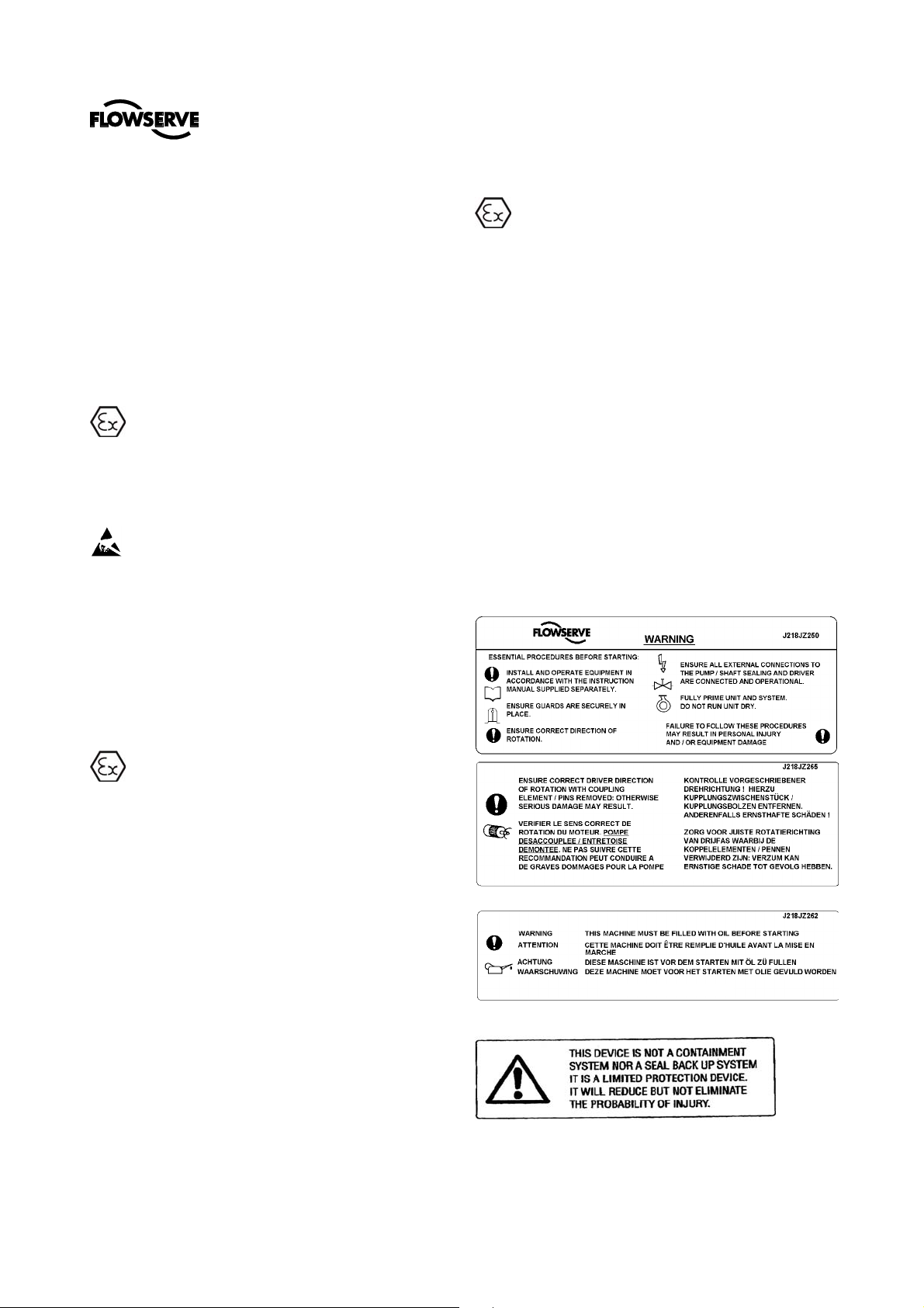
1.7 Name plate and safety labels
1.7.1 Nameplate
For details of nameplate, see the Declaration of
Conformity and section 3.
1.7.2 Safety labels
Oil lubricated units only:
DurcoShieldTM (Splash/Shaft Guard) only:
Page 7 of 68 flowserve.com
MARK 3 USER INSTRUCTIONS ENGLISH 71569102 08-06
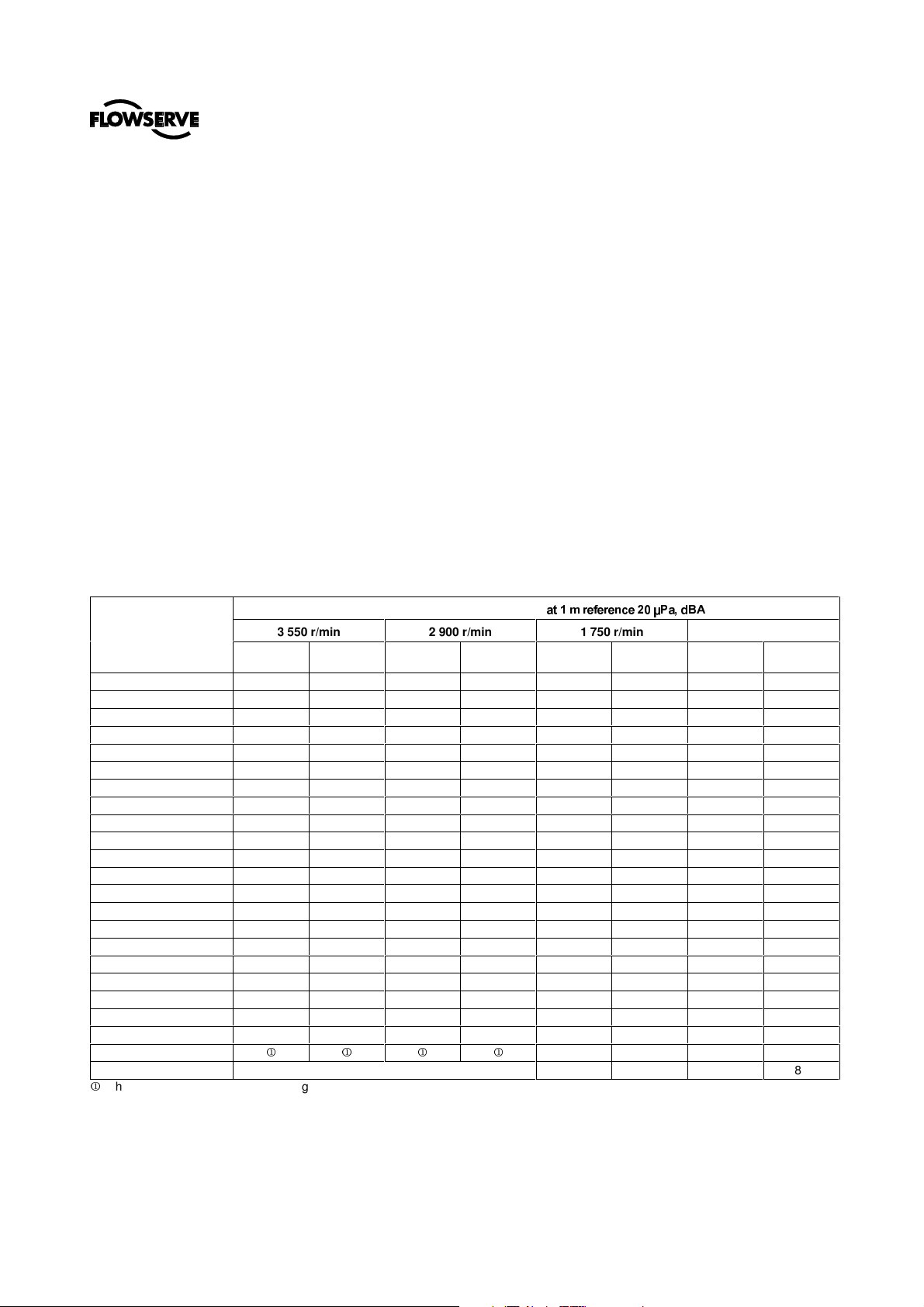
1.8 Noise level
Attention must be given to the exposure of personnel
to the noise, and local legislation will define when
guidance to personnel on noise limitation is required,
and when noise exposure reduction is mandatory.
This is typically 80 to 85 dBA.
The usual approach is to control the exposure time to
the noise or to enclose the machine to reduce emitted
sound. You may have already specified a limiting
noise level when the equipment was ordered,
however if no noise requirements were defined, then
attention is drawn to the following table to give an
indication of equipment noise level so that you can
take the appropriate action in your plant.
Pump noise level is dependent on a number of
operational factors, flow rate, pipework design and
acoustic characteristics of the building, and so the
values given are subject to a 3 dBA tolerance and
cannot be guaranteed.
Similarly the motor noise assumed in the “pump and
motor” noise is that typically expected from standard
and high efficiency motors when on load directly driving
the pump. Note that a motor driven by an inverter may
show an increased noise at some speeds.
If a pump unit only has been purchased for fitting with
your own driver then the “pump only” noise levels in the
table should be combined with the level for the driver
obtained from the supplier. Consult Flowserve or a
noise specialist if assistance is required in combining
the values.
It is recommended that where exposure approaches
the prescribed limit, then site noise measurements
should be made.
The values are in sound pressure level LpA at 1 m
(3.3 ft) from the machine, for “free field conditions
over a reflecting plane”.
For estimating sound power level LWA (re 1pW) then
add 14 dBA to the sound pressure value.
Motor size
and speed
kW (hp)
<0.55(<0.75) 72 72 64 65 62 64 62 64
0.75 (1) 72 72 64 66 62 64 62 64
1.1 (1.5) 74 74 66 67 64 64 62 63
1.5 (2) 74 74 66 71 64 64 62 63
2.2 (3) 75 76 68 72 65 66 63 64
3 (4) 75 76 70 73 65 66 63 64
4 (5) 75 76 71 73 65 66 63 64
5.5 (7.5) 76 77 72 75 66 67 64 65
7.5 (10) 76 77 72 75 66 67 64 65
11(15) 80 81 76 78 70 71 68 69
15 (20) 80 81 76 78 70 71 68 69
18.5 (25) 81 81 77 78 71 71 69 71
22 (30) 81 81 77 79 71 71 69 71
30 (40) 83 83 79 81 73 73 71 73
37 (50) 83 83 79 81 73 73 71 73
45 (60) 86 86 82 84 76 76 74 76
55 (75) 86 86 82 84 76 76 74 76
75 (100) 87 87 83 85 77 77 75 77
90 (120) 87 88 83 85 77 78 75 78
110 (150) 89 90 85 87 79 80 77 80
150 (200) 89 90 85 87 79 80 77 80
200 (270)
300 (400) – 87 90 85 86
The noise level of machines in this range will most likely be of values which require noise exposure control, but typical values are inappropriate.
Note: for 1 180 and 960 r/min reduce 1 450 r/min values by 2 dBA. For 880 and 720 r/min reduce 1 450 r/min values by 3 dBA.
3 550 r/min 2 900 r/min 1 750 r/min 1 450 r/min
Pump
only
Pump and
Typical sound pressure level L
motor
Pump
only
Pump and
motor
pA
Pump
only
85
Pump and
motor
87 83
Pump
only
Pump and
motor
85
Page 8 of 68 flowserve.com
MARK 3 USER INSTRUCTIONS ENGLISH 71569102 08-06
2 TRANSPORT AND STORAGE
2.1 Consignment receipt and unpacking
Immediately after receipt of the equipment it must be
checked against the delivery/shipping documents for
its completeness and that there has been no damage
in transportation. Any shortage and/or damage must
be reported immediately to Flowserve Pump Division
and must be received in writing within ten days of
receipt of the equipment. Later claims cannot be
accepted.
Check any crate, boxes or wrappings for any
accessories or spare parts that may be packed
separately with the equipment or attached to side
walls of the box or equipment.
Each product has a unique serial number. Check
that this number corresponds with that advised and
always quote this number in correspondence as well
as when ordering spare parts or further accessories.
2.2 Handling
Boxes, crates, pallets or cartons may be unloaded
using fork lift vehicles or slings dependent on their
size and construction.
2.3 Lifting
2.3.1.3 Bearing housing [3200]
Group 1: insert a sling between the upper and lower
support ribs between the housing barrel and the
casing attachment flange. Use a choker hitch when
slinging. (Make sure there are no sharp edges on the
bottom side of the ribs that could cut the sling.)
Group 2 and 3: insert either a sling or hook through
the lifting lug located on the top of the housing.
2.3.1.4 Power end
Same as bearing housing.
2.3.1.5 Bare pump
Horizontal pumps: sling around the pump discharge
nozzle and around the outboard end of the bearing
housing with separate slings. Choker hitches must be
used at both attachment points and pulled tight. Make
sure the completion of the choker hitch on the discharge
nozzle is toward the coupling end of the pump shaft as
shown in figure 2-1. The sling lengths should be adjusted
to balance the load before attaching the lifting hook.
Pumps and motors often have integral
lifting lugs or eye bolts. These are intended for use in
only lifting the individual piece of equipment.
Do not use eye bolts or cast-in lifting
lugs to lift pump, motor and baseplate assemblies.
To avoid distortion, the pump unit
should be lifted as shown.
Care must be taken to lift components
or assemblies above the center of gravity to prevent
the unit from flipping. This is especially true with
In-Line pumps.
2.3.1 Lifting pump components
2.3.1.1 Casing [1100]
Use a choker hitch pulled tight around the discharge
nozzle.
2.3.1.2 Rear cover [1220]
Insert an eye hook in the drilled and tapped hole at
the top of the cover. Use either a sling or hook
through the eye bolt.
Figure 2-1
In-Line pumps: lift with two slings through the pump
adapter on opposite sides of the shaft. (Figure 2-2.)
Bare pump with motor adapter (In-Line only): lift with
two slings through the motor adapter shaft holes.
This method is also used to lift the bare motor
adapter. (Figure 2-2.)
Page 9 of 68 flowserve.com
MARK 3 USER INSTRUCTIONS ENGLISH 71569102 08-06
2.4 Storage
Store the pump in a clean, dry location
away from vibration. Leave flange covers in place to
keep dirt and other foreign material out of pump
casing. Turn the pump shaft at regular intervals to
prevent brinelling of the bearings and the seal faces,
if fitted, from sticking.
The pump may be stored as above for up to 6
months. Consult Flowserve for preservative actions
when a longer storage period is needed.
2.4.1 Short term storage and packaging
Normal packaging is designed to protect the pump
and parts during shipment and for dry, indoor storage
for up to six months or less. The following is an
overview of our normal packaging:
All loose unmounted items are packaged in a
•
water proof plastic bag and placed under the
coupling guard
• Inner surfaces of the bearing housing, shaft (area
through bearing housing) and bearings are coated
with Cortec VCI-329 rust inhibitor, or equal.
Figure 2-2
2.3.2 Lifting pump, motor and baseplate assembly
2.3.2.1 Horizontal assemblies
If the baseplate has lifting holes cut in the sides at the
end (Type A Group 3, Type D and Type E bases) insert
lifting S hooks at the four corners and use slings or
chains to connect to the lifting eye. (Figure 2-1.) Do not
use slings through the lifting holes.
For other baseplates, sling around the pump discharge
nozzle, and around the outboard end of the motor frame
using choker hitches pulled tight. (Figure 2-1.)
The sling should be positioned so the weight is not
carried through the motor fan housing. Make sure the
completion of the choker hitch on the discharge
nozzle is toward the coupling end of the pump shaft
as shown in figure 2-1.
2.3.2.2 In-Line assemblies
If the pump is to be lifted as a complete assembly, the
motor lifting lugs must be used to ensure that the
assembly does not flip over. Check with motor
supplier for lifting lug capacities. If there is any
uncertainty, the motor should be removed prior to
moving the pump. (Figure 2-2.)
Bearing housings are not filled with oil
prior to shipment
Regreasable bearings are packed with grease
•
(EXXON POLYREX EM for horizontal pumps and
EXXON UNIREX N3 for In-Line pumps)
The internal surfaces of ferrous casings, covers,
•
flange faces, and the impeller surface are
sprayed with Cortec VCI-389, or equal
• Exposed shafts are taped with Polywrap
• Flange covers are secured to both the suction
and discharge flanges
• In some cases with assemblies ordered with
external piping, components may be
disassembled for shipment
• The pump must be stored in a covered, dry location
2.4.2 Long term storage and packaging
Long term storage is defined as more than six
months, but less than 12 months. The procedure
Flowserve follows for long term storage of pumps is
given below. These procedures are in addition to the
short term procedure.
• Each assembly is hermetically (heat) sealed from
the atmosphere by means of tack wrap sheeting
and rubber bushings (mounting holes)
• Desiccant bags are placed inside the tack
wrapped packaging
A solid wood box is used to cover the assembly
•
This packaging will provide protection for up to twelve
months from humidity, salt laden air, dust etc.
Page 10 of 68 flowserve.com

MARK 3 USER INSTRUCTIONS ENGLISH 71569102 08-06
Serial No.
Equipment No.
Purchase Order
Model
Size
MDP
Material
Date DD/MMM/YY
After unpacking, protection will be the responsibility of
the user. Addition of oil to the bearing housing will
remove the inhibitor. If units are to be idle for extended
periods after addition of lubricants, inhibitor oils and
greases should be used. Every three months, the pump
shaft should be rotated approximately 10 revolutions.
2.5 Recycling and end of product life
At the end of the service life of the product or its parts,
the relevant materials and parts should be recycled or
disposed of using an environmentally acceptable
method and in accordance with local regulations. If the
product contains substances that are harmful to the
environment, these should be removed and disposed of
in accordance with current local regulations. This also
includes the liquids and/or gases that may be used in
the "seal system" or other utilities.
Make sure that hazardous substances are
disposed of safely and that the correct personal
protective equipment is used. The safety
specifications must be in accordance with the current
local regulations at all times.
3 DESCRIPTION
3.1 Configurations
The Durco Mark 3 chemical process pumps are
metallic , single stage, sealed, centrifugal pumps.
The horizontal family conforms to ASME B73.1M,
which has a centerline discharge and is represented
by our Standard, Sealmatic, Unitized self-priming,
Recessed impeller and Lo-Flo pump models. The
vertical pump or In-Line conforms to ASME B73.2M.
Figure 3-1: Nameplate mounted to housing
2K6X4 M-13A/12.5 RV
The Prima
3 ™
is an ANSI 3A power end adapted to other
pump models from Flowserve as well as from other
pump manufacturers. Only the information in this
manual involving the ANSI 3A power end may be used
when Installing, Operating or Maintaining a pump that
has been upgraded to a Prima
regarding the pump type must be obtained from the
original pump manufacturer’s User Instructions.
3 ™
. All other information
3.2 Nomenclature
The pump size will be engraved on the nameplate
typically as below:
2 K 6 X 4 M - 13 A /12.5 RV
• Frame size
“2" indicates a medium size pump frame (in this
example, a Group 2)
1 = Group 1 (small frame)
2 = Group 2 (medium frame)
3 = Group 3 (large frame)
Power end
•
K = Mark 3 style power end
Mark 3A – Standard
ANSI 3A – Optional (3 year guarantee)
J = Mark 3 style PE arranged for Mark 2 wet end
(No letter and no preceding number indicates a
Mark 2 power end)
• “6” = nominal suction port size (in.)
• “4” = Nominal discharge port size (in.)
• Modifier for “specialty pumps”
Blank or no letter = standard pump
M = Sealmatic
R = recessed impeller
US = unitized self-priming
V = vertical In-Line
LF = Lo-Flo
• Nominal maximum impeller diameter. “13” = 13 in.
• Pump design variation
A = This pump has been redesigned from an earlier
version. The impeller and casing are no longer
interchangeable with the earlier version.
H = This pump is designed for a higher flow capacity
than another pump with the same basic
designation. (Examples: 4X3-10 and 4X3-10H;
6X4-10 and 6X4-10H; 10X8-16 and 10X8-16H.
HH = This pump is designed for a higher head than
another pump with the same basic designation.
(Example: 4X3-13 and 4X3-13HH.)
• Actual impeller size
“12.5” = 12 ½ in. diameter; 8.13 = 8 LQ
10.75 = 10 ¾ in
(Previous annotation: 124 = 12 4/8 or 12 ½ in.
diameter; 83 = 8 LQ
• Impeller style
RV = reverse vane impeller; OP = Open impeller
Page 11 of 68 flowserve.com

MARK 3 USER INSTRUCTIONS ENGLISH 71569102 08-06
3.3 Design of major parts
3.3.1 Pump casing
Removal of the casing is not required when performing
maintenance of the rotating element. The pump is
designed with a gasket perpendicular to the shaft
allowing the rotating element to be easily removed
(back pull out).
3.3.2 Impeller
Depending on the product, the impeller is either reverse
vane or open.
3.3.3 Shaft/sleeve
Solid and sleeved shafts are available, supported on
bearings, threaded impeller end and keyed drive end.
3.3.4 Pump bearings and lubrication
Ball bearings are fitted as standard and may be either
oil or grease lubricated.
3.3.5 Bearing housing
Large oil bath reservoir.
3.3.6 Seal chamber (cover plate)
The seal chamber has a spigot (rabbet) fit between
the pump casing and bearing housing (adapter) for
optimum concentricity. The design enables a number
of sealing options to be fitted.
3.3.7 Shaft seal
The mechanical seal(s), attached to the pump shaft,
seals the pumped liquid from the environment. Gland
packing may be fitted as an option.
3.3.8 Driver
The driver is normally an electric motor. Different drive
configurations may be fitted such as internal combustion
engines, turbines, hydraulic motors etc driving via
couplings, belts, gearboxes, drive shafts etc.
3.3.9 Accessories
Accessories may be fitted when specified by the
customer.
3.4 Performance and operation limits
This product has been selected to meet the
specification of your purchase order. See section 1.5.
The following data is included as additional information
to help with your installation. It is typical, and factors
such as liquid being pumped, temperature, material of
construction, and seal type may influence this data. If
required, a definitive statement for your application can
be obtained from Flowserve.
3.4.1 Alloy cross reference chart
Figure 3-2 is the Alloy cross-reference chart for all
Mark 3 pumps.
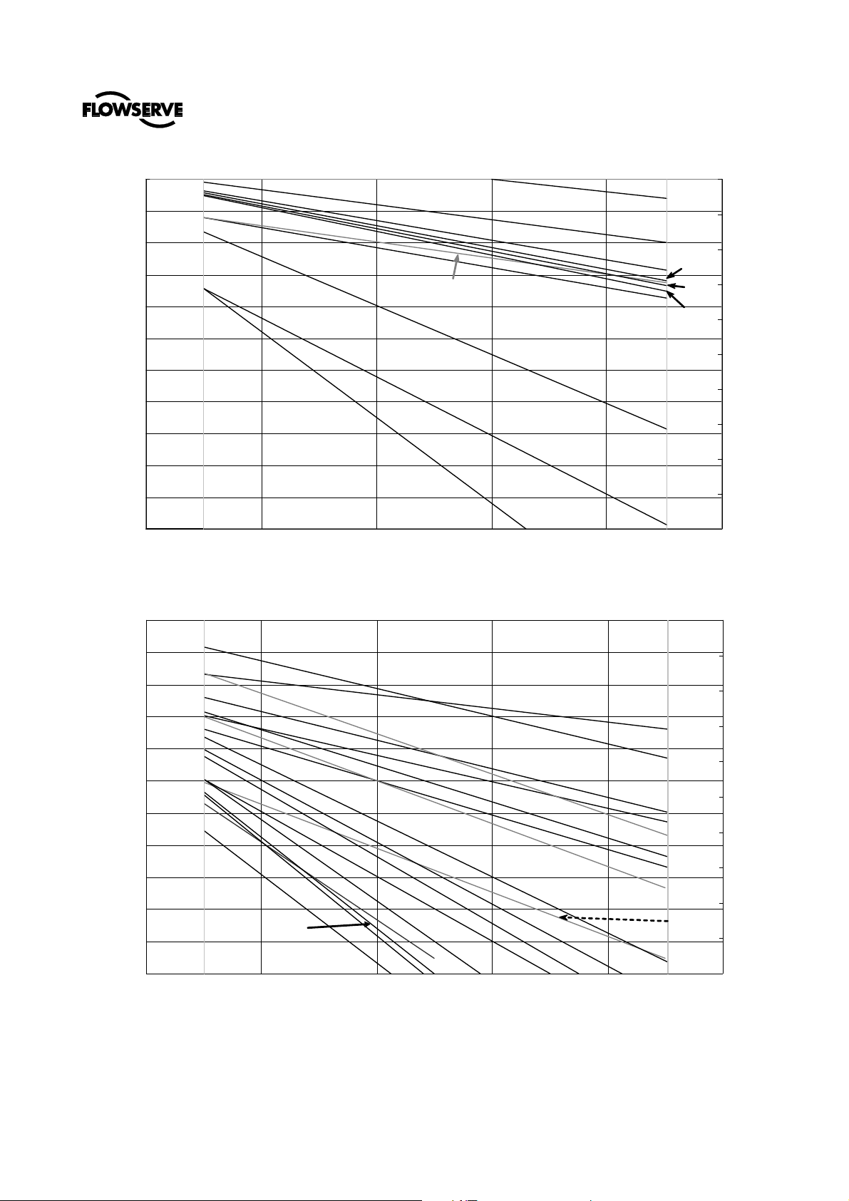
3.4.2 Pressure-temperature ratings
The pressure-temperature (P-T) ratings for Mark 3
pumps are shown in figures 3-3 and 3-4. Determine
the appropriate casing “Material Group No.” in Figure
3-2. Interpolation may be used to find the pressure
rating for a specific temperature.
Example:
The pressure temperature rating for an ANSI
standard GP2-10 in. pump with Class 300 flanges
and CF8M construction at an operating temperature
of 149 Û&LVIRXQGDVIROORZV
a) The correct pressure-temperature chart is Figure
3-4C.
b) From Figure 3-2, the correct material group for
CF8M is 2.2.
c) From Figure 3-4C, the pressure-temperature
rating is 21.5 bar.
The maximum discharge pressure must be less
than or equal to the P-T rating. Discharge pressure
may be approximated by adding the suction pressure
and the differential head developed by the pump.
3.4.3 Suction pressure limits
The suction pressure limits for Mark 3 pumps with
reverse vane impellers is limited by the values given in
figure 3-5 and by the P-T ratings.
Suction pressure for pump sizes 10x8-14, 8x6-16A,
10x8-16 and 10x8-16H (up to a maximum liquid
specific gravity of 2.0) is limited only by the P-T
ratings. Suction pressure for pumps with open
impellers is also limited only by the P-T ratings.
The suction pressure limits for Sealmatic pumps are
determined by the repeller head capability found in
Bulletin P-18-102e.
3.4.4 Minimum continuous flow
The minimum continuous flow (MCF) is based on a
percentage of the best efficiency point (BEP). Figure
3-7 identifies the MCF for all Mark 3 pump models
with the exception of the Lo-Flo pump line; there is no
MCF associated with this product line.
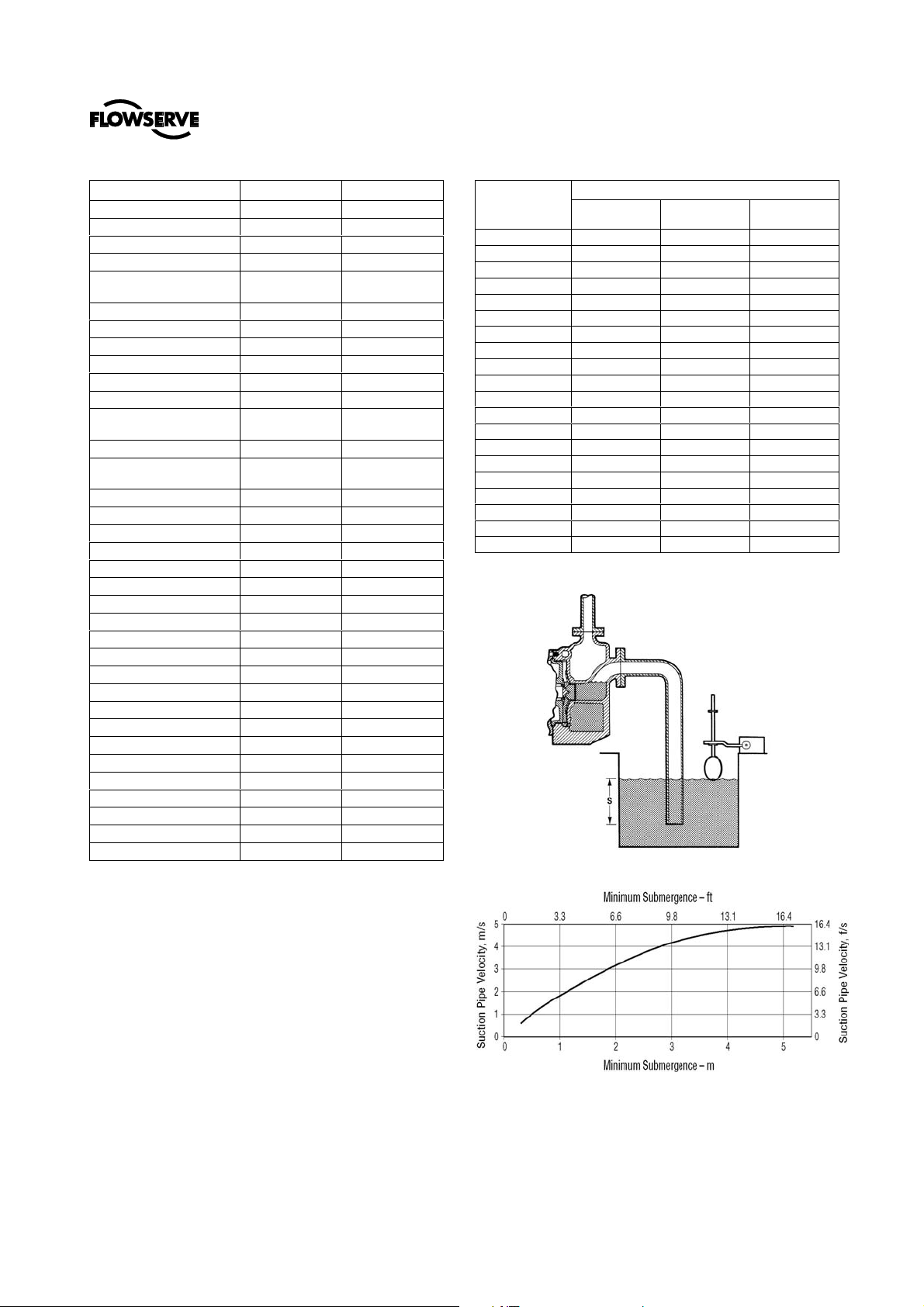
3.4.5 Minimum suction pipe submergence
The minimum submergence is shown in figure 3-8
and 3-9 for Unitized self-priming pumps.
Page 12 of 68 flowserve.com

MARK 3 USER INSTRUCTIONS ENGLISH 71569102 08-06
Figure 3-2: Alloy cross-reference chart
Flowserve
material code
E3020 Ductile iron DCI None None A395, Gr. 60-40-18 1.0
E3033 High chrome iron CR28 None None A532 class 3 Cr
E4027 High chrome iron CR29 None None None Cr
E4028 High chrome iron CR35 None None None Cr
C3009 Carbon steel DS None Carbon steel A216 Gr. WCB 1.1
C3062 Durco CF8 D2 CF8 304 A744, Gr. CF8 2.1
C3069 Durco CF3 D2L CF3 304L A744, Gr. CF3 2.1
C3063 Durco CF8M D4 CF8M 316 A744, Gr. CF8M 2.2
C3067 Durco CF3M D4L CF3M 316L A744, Gr. CF3M 2.2
C3107 Durcomet 100 CD4M CD4MCuN
C4028 Durimet 20 D20 CN7M Alloy 20 A744, Gr. CN7M 3.17
C4029 Durcomet 5 DV None None None 2.2
K3005 Durco CY40 DINC CY40
K3007 Durco M35 DMM M351
K3008 Nickel DNI CZ100 Nickel 200 A494, Gr. CZ100 3.2
K4007 Chlorimet 2 DC2 N7M
K4008 Chlorimet 3 DC3 CW6M
E3041
E3042
E4035
D4036 Durco DC8 DC8 None None None H3004 Titanium Ti None Titanium B367, Gr. C3 Ti
H3005 Titanium-Pd TiP None Titanium-Pd B367, Gr. C8A Ti
H3007 Zirconium Zr None Zirconium B752, Gr. 702C Ti
Duriron, Durichlor 51 and Superchlor are registered trademarks of Flowserve Corporation.
Ferralium is a registered trademark of Langley Alloys.
Hastelloy is a registered trademark of Haynes International, Inc.
Inconel and Monel are registered trademarks of International Nickel Co. Inc.
Designation
Duriron
Durichlor 51
Superchlor
Durco legacy
codes
D None None A518, Gr. 1 No load
D51 None None A518, Gr. 2 No load
SD51 None None A518, Gr. 2 No load
ACI
designation
Equivalent wrought
designation
Ferralium
Inconel 600
Monel 400
Hastelloy B
Hastelloy C
ASTM
specifications
A995, Gr. CD4MCuN 2.8
A494, Gr. CY40 3.5
A494, Gr. M35-1 3.4
A494, Gr. N7M 3.7
A494, Gr. CW6M 3.8
Material
Group No.
Notes:
Page 13 of 68 flowserve.com

MARK 3 USER INSTRUCTIONS ENGLISH 71569102 08-06
Figure 3-3: Class 150 flanges
Temp
ºC
( ºF)
-73
(-100)
-29
(-20)
-18
(0)
38
(100)
93
(200)
149
(300)
171
(340)
204
(400)
260
(500)
316
(600)
343
(650)
371
(700)
1.0 1.1 2.1 2.2 2.8 3.2 3.4 3.5 3.7 3.8 3.17 Ti Cr
–
17.2
(250)
17.2
(250)
17.2
(250)
16.2
(235)
14.8
(215)
14.4
(209)
13.8
(200)
11.7
(170)
9.7
(140)
8.6
(125)
–
–
19.7
(285)
19.7
(285)
19.7
(285)
17.9
(260)
15.9
(230)
15.0
(218)
13.8
(200)
11.7
(170)
9.7
(140)
8.6
(125)
7.6
(110)
19.0
(275)
19.0
(275)
19.0
(275)
19.0
(275)
15.9
(230)
14.1
(205)
13.7
(199)
13.1
(190)
11.7
(170)
9.7
(140)
8.6
(125)
7.6
(110)
19.0
(275)
19.0
(275)
19.0
(275)
19.0
(275)
16.2
(235)
14.8
(215)
14.3
(207)
13.4
(195)
11.7
(170)
9.7
(140)
8.6
(125)
7.6
(110)
19.7
(285)
19.7
(285)
19.7
(285)
19.7
(285)
17.9
(260)
15.9
(230)
15.0
(218)
13.8
(200)
11.7
(170)
9.7
(140)
– –
–
Material Group No.
bar (psi)
9.7
(140)
9.7
(140)
9.7
(140)
9.7
(140)
9.7
(140)
9.7
(140)
9.7
(140)
9.7
(140)
9.7
(140)
9.7
(140)
15.9
(230)
15.9
(230)
15.9
(230)
15.9
(230)
13.8
(200)
13.1
(190)
13.0
(188)
12.8
(185)
11.7
(170)
9.7
(140)
8.6
(125)
–
7.6
(110)
15.2
(220)
15.2
(220)
15.2
(220)
15.2
(220)
13.8
(200)
12.4
(180)
12.1
(176)
11.7
(170)
11.0
(160)
9.7
(140)
8.6
(125)
7.6
(110)
20.0
(290)
20.0
(290)
20.0
(290)
20.0
(290)
17.9
(260)
15.9
(230)
15.0
(218)
13.8
(200)
11.7
(170)
9.7
(140)
8.6
(125)
7.6
(110)
20.0
(290)
20.0
(290)
20.0
(290)
20.0
(290)
17.9
(260)
15.9
(230)
15.0
(218)
13.8
(200)
11.7
(170)
9.7
(140)
8.6
(125)
7.6
(110)
Figure 3-4A: Group 2 – 13 in. In-Lines and Group 3 pumps with Class 300 flanges
Temp
ºC
( ºF)
-73
(-100)
-29
(-20)
-18
(0)
38
(100)
93
(200)
149
(300)
204
(400)
260
(500)
316
(600)
343
(650)
371
(700)
1.1 2.1 2.2 2.8 3.2 3.4 3.5 3.7 3.8 3.17 Ti
–
24.1
(350)
24.1
(350)
24.1
(350)
22.0
(319)
21.4
(310)
20.7
(300)
19.6
(284)
17.9
(260)
17.4
(253)
17.4
(253)
24.1
(350)
24.1
(350)
24.1
(350)
24.1
(350)
20.1
(292)
18.1
(263)
16.6
(241)
15.3
(222)
14.6
(211)
14.4
(209)
14.2
(207)
24.1
(350)
24.1
(350)
24.1
(350)
24.1
(350)
20.8
(301)
18.8
(272)
17.3
(250)
16.1
(233)
15.1
(219)
14.9
(216)
14.4
(209)
24.1
(350)
24.1
(350)
24.1
(350)
24.1
(350)
23.2
(336)
21.4
(310)
19.8
(287)
18.5
(268)
17.9
(259)
– –
– –
Material Group No.
bar (psi)
17.4
(252)
17.4
(252)
17.4
(252)
17.4
(252)
17.4
(252)
17.4
(252)
17.4
(252)
17.4
(252)
17.4
(252)
24.1
(350)
24.1
(350)
24.1
(350)
24.1
(350)
21.3
(309)
19.9
(289)
19.3
(280)
19.1
(277)
19.1
(277)
19.1
(277)
19.1
(277)
24.1
(350)
24.1
(350)
24.1
(350)
24.1
(350)
22.9
(332)
21.4
(310)
19.9
(288)
19.3
(280)
19.2
(278)
19.0
(276)
18.9
(274)
24.1
(350)
24.1
(350)
24.1
(350)
24.1
(350)
24.1
(350)
23.5
(341)
22.7
(329)
21.4
(310)
19.5
(282)
19.0
(275)
18.3
(266)
24.1
(350)
24.1
(350)
24.1
(350)
24.1
(350)
24.1
(350)
23.5
(341)
22.7
(329)
21.4
(310)
19.5
(282)
19.0
(275)
18.3
(266)
15.9
(230)
15.9
(230)
15.9
(230)
15.9
(230)
13.8
(200)
12.4
(180)
11.9
(172)
11.0
(160)
10.3
(150)
9.7
(140)
–
–
20.0
(290)
20.0
(290)
20.0
(290)
20.0
(290)
17.9
(260)
15.9
(230)
15.0
(218)
13.8
(200)
11.7
(170)
(140)
(125)
(110)
24.1
(350)
24.1
(350)
24.1
(350)
24.1
(350)
20.9
(303)
18.7
(271)
16.9
(245)
15.7
(228)
14.5
(210)
–
–
9.7
8.6
7.6
–
–
12.6
(183)
12.6
(183)
12.6
(183)
12.6
(183)
12.6
(183)
–
–
–
–
–
24.1
(350)
24.1
(350)
24.1
(350)
24.1
(350)
21.4
(310)
18.7
(271)
15.9
(231)
13.2
(191)
10.5
(152)
9.1
(132)
7.7
(112)
Page 14 of 68 flowserve.com

MARK 3 USER INSTRUCTIONS ENGLISH 71569102 08-06
Figure 3-4B: Group 2 - 13 in. Lo-Flo pumps with Class 300 flanges
Temp
ºC
( ºF)
-73
(-100)
-29
(-20)
-18
(0)
38
(100)
93
(200)
149
(300)
204
(400)
260
(500)
316
(600)
343
(650)
371
(700)
1.0 1.1 2.1 2.2 2.8 3.2 3.4 3.5 3.7 3.8 3.17 Ti
–
31.0
(450)
31.0
(450)
31.0
(450)
29.1
(422)
27.4
(397)
25.5
(369)
24.0
(348)
22.5
(327)
21.8
(316)
–
–
31.0
(450)
31.0
(450)
31.0
(450)
28.3
(410)
27.5
(398)
26.6
(386)
25.2
(365)
23.1
(334)
22.4
(325)
22.4
(325)
31.0
(450)
31.0
(450)
31.0
(450)
31.0
(450)
25.9
(375)
23.3
(338)
21.3
(309)
19.7
(285)
18.7
(272)
18.5
(269)
18.3
(266)
31.0
(450)
31.0
(450)
31.0
(450)
31.0
(450)
26.7
(388)
24.1
(350)
22.2
(322)
20.7
(300)
19.4
(281)
19.2
(2780
18.5
(269)
Material Group No.
31.0
(450)
31.0
(450)
31.0
(450)
31.0
(450)
29.8
(432)
27.5
(399)
25.4
(369)
23.8
(345)
23.0
(333)
– –
– –
bar (psi)
17.4
(252)
17.4
(252)
17.4
(252)
17.4
(252)
17.4
(252)
17.4
(252)
17.4
(252)
17.4
(252)
17.4
(252)
24.1
(350)
24.1
(350)
24.1
(350)
24.1
(350)
21.3
(309)
19.9
(289)
19.3
(280)
19.1
(277)
19.1
(277)
19.1
(277)
19.1
(277)
Figure 3-4C: All other Class 300 flanges
Temp
ºC
( ºF)
-73
(-100)
-29
(-20)
-18
(0)
38
(100)
93
(200)
149
(300)
204
(400)
260
(500)
316
(600)
343
(650)
371
(700)
1.1 2.1 2.2 2.8 3.2 3.4 3.5 3.7 3.8 3.17 Ti
–
27.6
(400)
27.6
(400)
27.6
(400)
25.2
(365)
24.4
(354)
23.7
(343)
22.4
(324)
20.5
(297)
19.9
(289)
19.9
(289)
27.6
(400)
27.6
(400)
27.6
(400)
27.6
(400)
23.0
(333)
20.7
(300)
19.0
(275)
17.5
(253)
16.7
(242)
16.5
(239)
16.3
(236)
27.6
(400)
27.6
(400)
27.6
(400)
27.6
(400)
23.7
(344)
21.5
(311)
19.7
(286)
18.4
(267)
17.2
(250)
17.0
(247)
16.5
(239)
27.6
(400)
27.6
(400)
27.6
(400)
27.6
(400)
26.5
(384)
24.5
(355)
22.6
(328)
21.1
(307)
20.4
(296)
–
– –
Material Group No.
bar (psi)
17.4
(252)
17.4
(252)
17.4
(252)
17.4
(252)
17.4
(252)
17.4
(252)
17.4
(252)
17.4
(252)
17.4
(252)
–
24.1
(350)
24.1
(350)
24.1
(350)
24.1
(350)
21.3
(309)
19.9
(289)
19.3
(280)
19.1
(277)
19.1
(277)
19.1
(277)
19.1
(277)
24.1
(350)
24.1
(350)
24.1
(350)
24.1
(350)
22.9
(332)
21.4
(310)
19.9
(288)
19.3
(280)
19.2
(278)
19.0
(276)
18.9
(274)
27.6
(400)
27.6
(400)
27.6
(400)
27.6
(400)
26.1
(379)
24.4
(354)
22.7
(330)
22.1
(320)
21.9
(318)
21.8
(316)
21.6
(313)
(450)
(450)
(450)
(450)
(450)
(438)
(423)
(399)
(363)
(354)
(342)
27.6
(400)
27.6
(400)
27.6
(400)
27.6
(400)
27.6
(400)
26.8
(389)
25.9
(376)
24.5
(355)
22.2
(323)
21.7
(315)
21.0
(304)
31.0
31.0
31.0
31.0
31.0
30.2
29.2
27.5
25.0
24.4
23.6
31.0
(450)
31.0
(450)
31.0
(450)
31.0
(450)
31.0
(450)
30.2
(438)
29.2
(423)
27.5
(399)
25.0
(363)
24.4
(354)
23.6
(342)
27.6
(400)
27.6
(400)
27.6
(400)
27.6
(400)
27.6
(400)
26.8
(389)
25.9
(376)
24.5
(355)
22.2
(323)
21.7
(315)
21.0
(304)
24.1
(350)
24.1
(350)
24.1
(350)
24.1
(350)
20.9
(303)
18.7
(271)
16.9
(245)
15.7
(228)
14.5
(210)
–
–
24.1
(350)
24.1
(350)
24.1
(350)
24.1
(350)
20.9
(303)
18.7
(271)
16.9
(245)
15.7
(228)
14.5
(210)
–
–
31.0
(450)
31.0
(450)
31.0
(450)
31.0
(450)
27.5
(399)
24.0
(348)
20.5
(297)
17.0
(246)
13.4
(195)
11.7
(170)
9.9
(144)
27.6
(400)
27.6
(400)
27.6
(400)
27.6
(400)
24.5
(355)
21.3
(309)
18.2
(264)
15.1
(219)
12.0
(173)
10.4
(151)
8.8
(128)
Page 15 of 68 flowserve.com
MARK 3 USER INSTRUCTIONS ENGLISH 71569102 08-06
Specific Gravity
Figure 3-5a: Suction pressure limits 1 750 r/min
27.5
25
22.5
20
17.5
15
12.5
10
7.5
400
11
360
10
9
7
4
8
6
5
320
280
240
200
160
3
120
5
Maximum Allowable Suction Pressure - bar
2.5
0
0.4 0.8 1.2 1.6 2 2.4
Figure 3-5b: Suction pressure limits 3 500 r/min
27.5
25
22.5
20
17.5
15
12.5
10
7.5
5
Maximum Allowable Suction Pressure - bar
2.5
0
0.4 0.8 1.2 1.6 2 2.4
3
1
Specific Gravity
80
Maximum Allowable Suction Pressure - psi
40
1
2
0
400
360
320
18
17
16
15
14
13
12
11
280
240
200
160
120
80
10
Maximum Allowable Suction Pressure - psi
40
2
4
65
987
0
Page 16 of 68 flowserve.com
MARK 3 USER INSTRUCTIONS ENGLISH 71569102 08-06
Figure 3-6: Suction pressure reference numbers
Pump size 1 750 3 500
1K 1.5x1-6 7 10
1K 3x1.5-6 10 15
1K 3x2-6 10 12
1K 2 x1.5V-6
1K 1.5x1-8
1K 1.5x1.5US-8
1K 2x1.5V-8
1K 3x1.5-8 4 4
1K 3x2V-7
2K 3x2-8 10 7
2K 4x3-8 10 13
2K 2x1-10A 8 3
2K 2x1.5V-10A
2K 2x1.5US-10A
2K 3x1.5-10A 10 17
2K 3x2-10A
2K 3x2V-10
In-Line
2K 4x3-10 6 2
2K 4x3-10H 3
2K 6x4-10 5 8
2K 6x4-10H 10
2K 3x1.5-13 9 5
2K 3x2-13 5 1
2K 4x3-13/13 1
2K 4x3-13/12 1
2K 4x3-13/11 max 1 2
2K 4x3-13HH 10
2K 6x4-13A 1
2K 6x4-13A/10.25 1
3K 8x6-14A 2
3K 10x8-14
3K 6x4-16
3K 8x6-16A
3K 10x8-16 & 16H
3K 10x8-17 3
Recessed impellers
Lo-Flo pumps
Open impellers
Notes:
1. Self-Primer and In-Line pumps not specifically listed above
are to use the standard pump ratings given.
For example: 2K 3x2V-13 and 2K 3x2US-13 pumps utilize the
standard 2K 3x2-13 ratings.
2. P-T: Only limited by Pressure-Temperature ratings.
3. Open impeller pumps including the Lo-Flo and Recessed
Impeller products are limited in suction pressure only by the
Pressure-Temperature ratings.
4. Sealmatic pump suction pressure is limited by the repeller.
PT
18
7 6
PT
PT
16
11
8 3
10
11
PT na
PT na
PT na
PT na
PT PT
PT PT
PT PT
14
9
na
na
na
na
na
na
?
na
na
Figure 3-7: Minimum continuous flow
Pump size
3 500/2 900
r/min
1K3x2-6 20% 10% 10%
1K3x2-7 25% 10% 10%
2K3x2-8 20% 10% 10%
2K4x3-8 20% 10% 10%
2K3x2-10 30% 10% 10%
2K4x3-10 30% 10% 10%
2K6x4-10 40% 10% 10%
2K6x4-10H n.a. 20% 10%
2K3x1.5-13 30% 10% 10%
2K3x2-13 40% 10% 10%
2K4x3-13 40% 20% 10%
2K4x3-13HH n.a. 50% 30%
2K6x4-13 60% 40% 10%
3K8x6-14 n.a. 40% 15%
3K10x8-14 n.a. 40% 10%
3K6x4-16 n.a. 50% 10%
3K8x6-16 n.a. 50% 10%
3K10x8-16 n.a. 50% 10%
3K10x8-17 n.a. 50% 10%
All other sizes 10% 10% 10%
MCF % of BEP
1 750/1 450
r/min
1 180/960
r/min
Figure 3-8: Minimum submergence
Figure 3-9: Minimum submergence
Page 17 of 68 flowserve.com
MARK 3 USER INSTRUCTIONS ENGLISH 71569102 08-06
4 INSTALLATION
Zirconium 702 or high chrome iron components
If any of the components of the pump
have been made of zirconium or high chrome iron,
the following precautionary measures should be
followed:
Use hand wrenches rather than impact wrenches
•
• This equipment should not be subjected to
sudden changes in temperature or pressure
Avoid striking this equipment with any sharp blows
•
Zirconium 705 and high chrome iron components
Avoid any repair or fabrication welds
on Zirconium 705 and high chrome iron components.
4.1 Location
The pump should be located to allow room for
access, ventilation, maintenance, and inspection with
ample headroom for lifting and should be as close as
practicable to the supply of liquid to be pumped.
Refer to the general arrangement drawing for the
pump set.
4.2 Part assemblies
The supply of motors and baseplates are optional.
As a result, it is the responsibility of the installer to
ensure that the motor is assembled to the pump and
aligned as detailed in section 4.5 and 4.8.
4.3 Foundation
4.3.1 Protection of openings and threads
When the pump is shipped, all threads and all
openings are covered. This protection/covering
should not be removed until installation. If, for any
reason, the pump is removed from service, this
protection should be reinstalled.
4.3.2 In-Line pump mounting
The Mark 3 In-Line can be supported in several ways:
• The pump may be supported by the piping; in
which case it is recommended that the suction
and discharge pipes be supported adjacent to the
pump nozzles
The pump may be supported under the casing
•
foot or on the optional “pump stand”
The “pump stand” will allow the pump to free stand
without the aid of piping. The pump stand may be
bolted (and grouted) into place. In this case, the
piping loads must be within the limits of the casing
and of the “pump stand” as found in section 4.6.
The most advantageous method is the one that
permits the pump to move with the piping. This
eliminates problems due to thermal expansion, as the
pump is designed to withstand forces that the piping
is normally capable of transmitting.
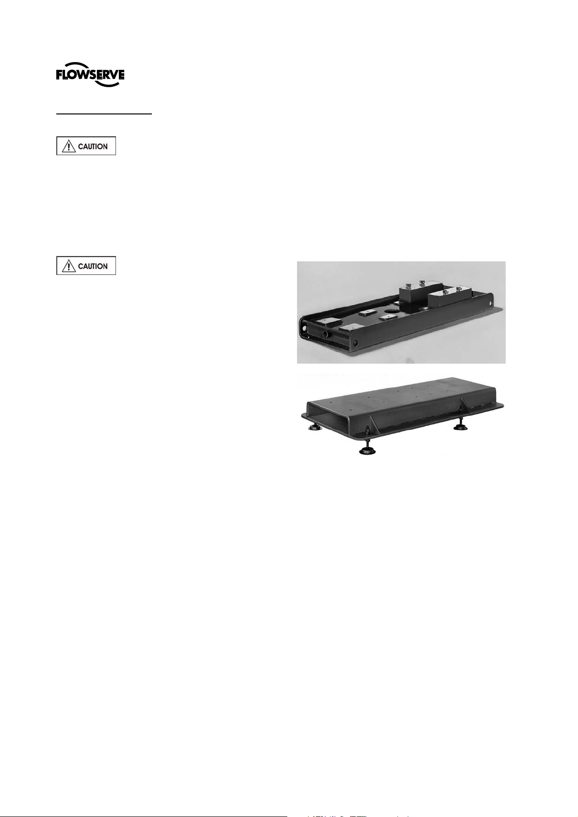
4.3.3 Rigid baseplates - overview
The function of a baseplate is to provide a rigid
foundation under a pump and its driver that maintains
alignment between the two. Baseplates may be
generally classified into two types:
• Foundation-mounted, grouted design. (Figure 4-1.)
• Stilt mounted, or free standing. (Figure 4-2.)
Figure 4-1
Figure 4-2
Baseplates intended for grouted installation are
designed to use the grout as a stiffening member.
Stilt mounted baseplates, on the other hand, are
designed to provide their own rigidity. Therefore the
designs of the two baseplates are usually different.
Regardless of the type of baseplate used, it must
provide certain functions that ensure a reliable
installation. Three of these requirements are:
1. The baseplate must provide sufficient rigidity to
assure the assembly can be transported and
installed, given reasonable care in handling,
without damage. It must also be rigid enough
when properly installed to resist operating loads.
2. The baseplate must provide a reasonably flat
mounting surface for the pump and driver. Uneven
surfaces will result in a soft-foot condition that may
make alignment difficult or impossible. Experience
indicates that a baseplate with a top surface
flatness of 1.25 mm/m (0.015 in./ft) across the
diagonal corners of the baseplate provides such a
mounting surface. Therefore, this is the tolerance
to which we supply our standard baseplate.
Page 18 of 68 flowserve.com
MARK 3 USER INSTRUCTIONS ENGLISH 71569102 08-06
Some users may desire an even flatter surface,
which can facilitate installation and alignment.
Flowserve will supply flatter baseplates upon
request at extra cost. For example, mounting
surface flatness of 0.17 mm/m (0.002 in./ft) is
offered on the Flowserve Type E “Ten Point”
baseplate shown in figure 4-1.
3. The baseplate must be designed to allow the user
to final field align the pump and driver to within their
own particular standards and to compensate for
any pump or driver movement that occurred during
handling. Normal industry practice is to achieve
final alignment by moving the motor to match the
pump. Flowserve practice is to confirm in our shop
that the pump assembly can be accurately aligned.
Before shipment, the factory verifies that there is
enough horizontal movement capability at the motor
to obtain a “perfect” final alignment when the
installer puts the baseplate assembly into its
original, top leveled, unstressed condition.
4.3.4 Stilt and spring mounted baseplates
Flowserve offers stilt and spring mounted baseplates.
(See figure 4-2 for stilt mounted option.) The low
vibration levels of Mark 3 pumps allow the use of
these baseplates - provided they are of a rigid design.
The baseplate is set on a flat surface with no tie down
bolts or other means of anchoring it to the floor.
General instructions for assembling these baseplates
are given below. For dimensional information, please
refer to the appropriate Flowserve “Sales print.”
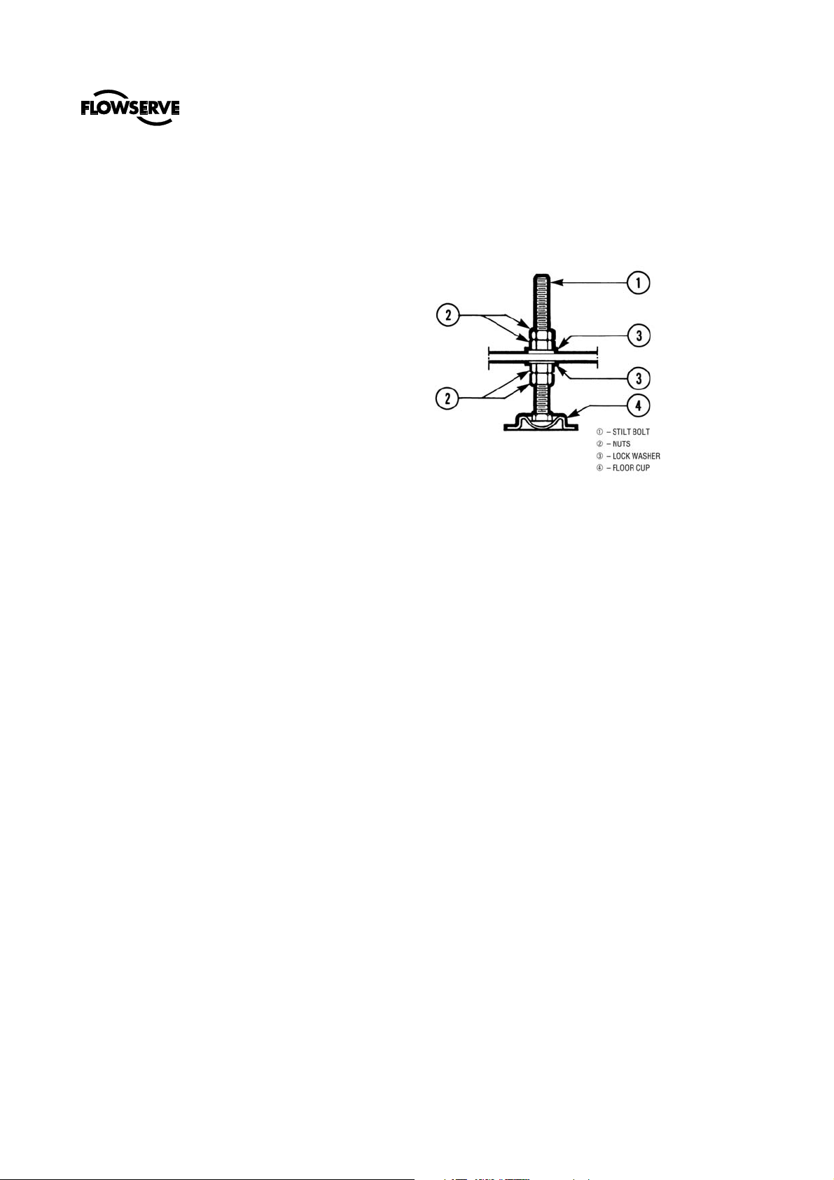
4.3.4.1 Stilt mounted baseplate assembly
instructions
Refer to figure 4-3.
a) Raise or block up baseplate/pump above the
floor to allow for the assembly of the stilts.
b) Predetermine or measure the approximate
desired height for the baseplate above the floor.
c) Set the bottom nuts [2] above the stilt bolt head
[1] to the desired height.
d) Assemble lock washer [3] down over the stilt bolt.
e) Assemble the stilt bolt up through hole in the
bottom plate and hold in place.
f) Assemble the lock washer [3] and nut [2] on the
stilt bolt. Tighten the nut down on the lock
washer.
g) After all four stilts have been assembled, position
the baseplate in place, over the floor cups [4]
under each stilt location, and lower the baseplate
to the floor.
h) Level and make final height adjustments to the
suction and discharge pipe by first loosening the
top nuts and turning the bottom nuts to raise or
lower the baseplate.
i) Tighten the top and bottom nuts at the lock
washer [3] first then tighten the other nuts.
j) It should be noted that the connecting pipelines
must be individually supported, and that the stilt
mounted baseplate is not intended to support
total static pipe load.
Figure 4-3
4.3.4.2 Stilt/spring mounted baseplate assembly
instructions
Refer to figure 4-4.
a) Raise or block up baseplate/pump above the
floor to allow for the assembly of the stilts.
b) Set the bottom nuts [4] above the stilt bolt head
[1]. This allows for 51 mm (2 in.) upward
movement for the final height adjustment of the
suction/discharge flange.
c) Assemble the lock washer [6] flat washer [5] and
bottom spring/cup assembly [2] down over the
stilt bolt [1].
d) Assemble the stilt bolt/bottom spring up through
hole in the bottom plate and hold in place.
e) Assemble top spring/cup assembly [3] down
over stilt bolt.
f) Assemble flat washer [5], lock washer [6] and
nuts [4] on the stilt bolt.
g) Tighten down top nuts, compressing the top
spring approximately 13 mm (0.5 in.). Additional
compression may be required to stabilize the
baseplate.
h) After all four stilts have been assembled,
position the baseplate in place, over the floor
cups [7] under each stilt location, and lower the
baseplate down to the floor.
i) Level and make final height adjustments to the
suction and discharge pipe by first loosening the
top nuts, and turning the bottom nuts to raise or
lower the baseplate.
j) Recompress the top spring to the compression
established in step g) and lock the nuts.
Page 19 of 68 flowserve.com
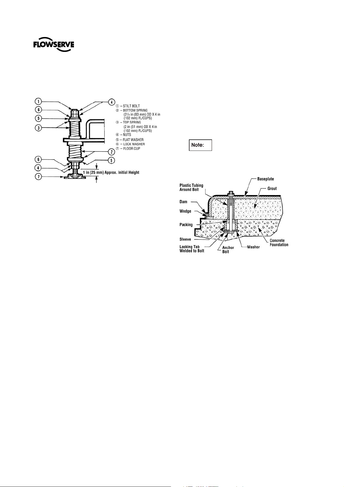
MARK 3 USER INSTRUCTIONS ENGLISH 71569102 08-06
k) It should be noted that the connecting pipelines
must be individually supported, and that the
spring mounted baseplate is not intended to
support total static pipe loads.
Figure 4-4
4.3.4.3 Stilt/spring mounted baseplates - motor
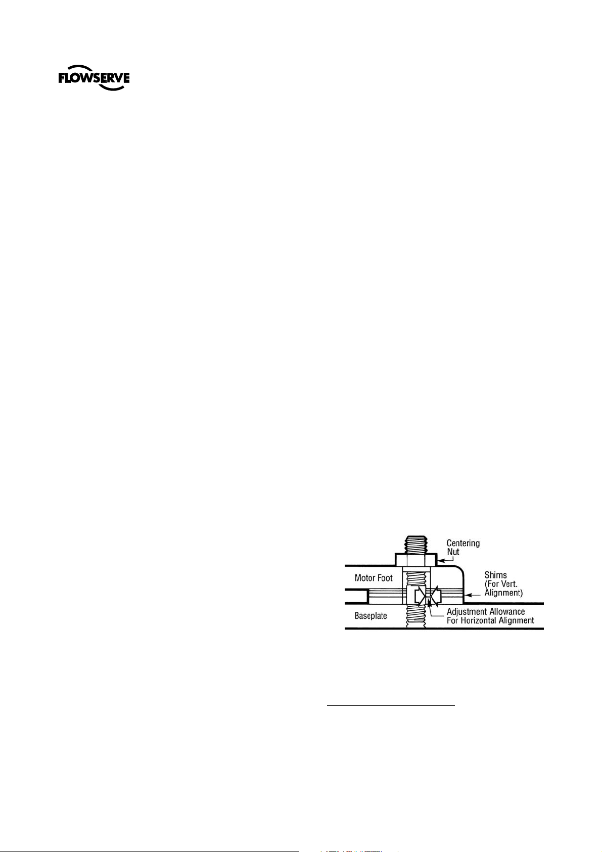
alignment
The procedure for motor alignment on stilt or spring
mounted baseplates is similar to grouted baseplates.
The difference is primarily in the way the baseplate is
leveled.
a) Level the baseplate by using the stilt adjusters.
(Shims are not needed as with grouted
baseplates.)
b) After the base is level, it is locked in place by
locking the stilt adjusters.
c) Next the initial pump alignment must be checked.
The vertical height adjustment provided by the
stilts allows the possibility of slightly twisting the
baseplate. If there has been no transit damage
or twisting of the baseplate during stilt height
adjustment, the pump and driver should be within
0.38 mm (0.015 in.) parallel, and 0.0025 mm/mm
(0.0025 in./in.) angular alignment. If this is not
the case, check to see if the driver mounting
fasteners are centered in the driver feet holes.
d) If the fasteners are not centered there was likely
shipping damage. Re-center the fasteners and
perform a preliminary alignment to the above
tolerances by shimming under the motor for
vertical alignment, and by moving the pump for
horizontal alignment.
e) If the fasteners are centered, then the baseplate
may be twisted. Slightly adjust (one turn of the
adjusting nut) the stilts at the driver end of the
baseplate and check for alignment to the above
tolerances. Repeat as necessary while
maintaining a level condition as measured from
the pump discharge flange.
f) Lock the stilt adjusters.
The remaining steps are as listed for new grouted
baseplates.
4.4 Grouting
a) The pump foundation should be located as close
to the source of the fluid to be pumped as
practical.
b) There should be adequate space for workers to
install, operate, and maintain the pump. The
foundation should be sufficient to absorb any
vibration and should provide a rigid support for
the pump and motor.
c) Recommended mass of a concrete foundation
should be three times that of the pump, motor
and base. Refer to figure 4-5.
Foundation bolts are imbedded in the
concrete inside a sleeve to allow some
movement of the bolt.
Figure 4-5
d) Level the pump baseplate assembly. If the
baseplate has machined coplanar mounting
surfaces, these machined surfaces are to be
referenced when leveling the baseplate. This may
require that the pump and motor be removed from
the baseplate in order to reference the machined
faces. If the baseplate is without machined
coplanar mounting surfaces, the pump and motor
are to be left on the baseplate. The proper
surfaces to reference when leveling the pump
baseplate assembly are the pump suction and
discharge flanges. DO NOT stress the baseplate.
e) Do not bolt the suction or discharge flanges of
the pump to the piping until the baseplate
foundation is completely installed. If equipped,
use leveling jackscrews to level the baseplate. If
jackscrews are not provided, shims and wedges
should be used. (See Figure 4-5.) Check for
levelness in both the longitudinal and lateral
directions. Shims should be placed at all base
anchor bolt locations, and in the middle edge of
the base if the base is more than 1.5 m (5 ft.)
long. Do not rely on the bottom of the baseplate
to be flat. Standard baseplate bottoms are not
machined, and it is not likely that the field
mounting surface is flat.
Page 20 of 68 flowserve.com
MARK 3 USER INSTRUCTIONS ENGLISH 71569102 08-06
f) After leveling the baseplate, tighten the anchor
bolts. If shims were used, make sure that the
baseplate was shimmed near each anchor bolt
before tightening. Failure to do this may result in
a twist of the baseplate, which could make it
impossible to obtain final alignment.
g) Check the level of the baseplate to make sure
that tightening the anchor bolts did not disturb
the level of the baseplate. If the anchor bolts did
change the level, adjust the jackscrews or shims
as needed to level the baseplate.
h) Continue adjusting the jackscrews or shims and
tightening the anchor bolts until the baseplate is
level.
i) Check initial alignment. If the pump and motor
were removed from the baseplate proceed with
step j) first, then the pump and motor should be
reinstalled onto the baseplate using Flowserve’s
factory preliminary alignment procedure as
described in section 4.5, and then continue with
the following. As described above, pumps are
given a preliminary alignment at the factory. This
preliminary alignment is done in a way that
ensures that, if the installer duplicates the factory
conditions, there will be sufficient clearance
between the motor hold down bolts and motor foot
holes to move the motor into final alignment. If the
pump and motor were properly reinstalled to the
baseplate or if they were not removed from the
baseplate and there has been no transit damage,
and also if the above steps where done properly,
the pump and driver should be within 0.38 mm
(0.015 in.) FIM (Full Indicator Movement) parallel,
and 0.0025 mm/mm (0.0025 in./in.) FIM angular. If
this is not the case, first check to see if the driver
mounting fasteners are centered in the driver feet
holes. If not, re-center the fasteners and perform a
preliminary alignment to the above tolerances by
shimming under the motor for vertical alignment,
and by moving the pump for horizontal alignment.
j) Grout the baseplate. A non-shrinking grout
should be used. Make sure that the grout fills
the area under the baseplate. After the grout
has cured, check for voids and repair them.
Jackscrews, shims and wedges should be
removed from under the baseplate at this time.
If they were to be left in place, they could rust,
swell, and cause distortion in the baseplate.
k) Run piping to the suction and discharge of the
pump. There should be no piping loads
transmitted to the pump after connection is
made. Recheck the alignment to verify that
there are no significant loads.
4.5 Initial alignment
4.5.1 Horizontal initial alignment procedure
The purpose of factory alignment is to ensure that the
user will have full utilization of the clearance in the
motor holes for final job-site alignment. To achieve
this, the factory alignment procedure specifies that
the pump be aligned in the horizontal plane to the
motor, with the motor foot bolts centered in the motor
holes. This procedure ensures that there is sufficient
clearance in the motor holes for the customer to field
align the motor to the pump, to zero tolerance. This
philosophy requires that the customer be able to
place the base in the same condition as the factory.
Thus the factory alignment will be done with the base
sitting in an unrestrained condition on a flat and level
surface. This standard also emphasizes the need to
ensure the shaft spacing is adequate to accept the
specified coupling spacer.
The factory alignment procedure is summarized
below:
a) The baseplate is placed on a flat and level
workbench in a free and unstressed position.
b) The baseplate is leveled as necessary. Leveling
is accomplished by placing shims under the rails
of the base at the appropriate anchor bolt hole
locations. Levelness is checked in both the
longitudinal and lateral directions.
c) The motor and appropriate motor mounting
hardware is placed on the baseplate and the motor
is checked for any planar soft-foot condition. If any
is present it is eliminated by shimming.
d) The motor feet holes are centered on the motor
mounting fasteners. This is done by using a
centering nut as shown in figure 4-6.
Figure 4-6
e) The motor is fastened in place by tightening the
nuts on two diagonal motor mounting studs.
f) The pump is put onto the baseplate and leveled.
The foot piece under the bearing housing is
adjustable. It is used to level the pump, if necessary.
Mark 3A and ANSI 3A design
If an adjustment is necessary, add or remove
shims [3126.1] between the foot piece and the
bearing housing.
Page 21 of 68 flowserve.com
 Loading...