


OPERATING
MANUAL
MODELS UG5000W, UG5000EW, UG5000EWFS
SOLVENT AND WATERBORNE
SPRAY GUN CLEANERS
CAUTION
RIGHT TANK
FOR WATER BORNE PAINTS ONLY
NOT DESIGNED
FOR USE WITH SOLVENT BASED PAINT
Conforms to Article 13(1)b ii, Council Directive 2014/34/EU
•• 381 Bentley Street, Markham ON L3R 9T2
WWW.UNIRAM.COM
CORPORATION
• Tel. 1-800-417-9133
• sales@uniram.com
EX9A 18 02 78342
002
Revised 2019-3

MANUAL - SPRAY GUN CLEANERS - UG5000W SERIES Revision 2019-3
CONTENTS
INTRODUCTION . . . . . . . . . . . . . . . . . . . . . . . . . . . . . . . . . . . . . . . . . . . . . . . . . . . . . . . . . . . . . . . . . . . . . . 3
FEATURES . . . . . . . . . . . . . . . . . . . . . . . . . . . . . . . . . . . . . . . . . . . . . . . . . . . . . . . . . . . . . . . . . . . . . . . . . . . 3
SETUP
INSPECTION . . . . . . . . . . . . . . . . . . . . . . . . . . . . . . . . . . . . . . . . . . . . . . . . . . . . . . . . . . . . . . . . . . . . . . . . . 3
INCLUDED PARTS . . . . . . . . . . . . . . . . . . . . . . . . . . . . . . . . . . . . . . . . . . . . . . . . . . . . . . . . . . . . . . . . . . . . 3
STRUCTURE . . . . . . . . . . . . . . . . . . . . . . . . . . . . . . . . . . . . . . . . . . . . . . . . . . . . . . . . . . . . . . . . . . . . . . . . . 4
LOCATION . . . . . . . . . . . . . . . . . . . . . . . . . . . . . . . . . . . . . . . . . . . . . . . . . . . . . . . . . . . . . . . . . . . . . . . . . . . 6
LEVELING, VENT AND AIR SUPPLY . . . . . . . . . . . . . . . . . . . . . . . . . . . . . . . . . . . . . . . . . . . . . . . . . . . . 6
SOLVENT SELECTION . . . . . . . . . . . . . . . . . . . . . . . . . . . . . . . . . . . . . . . . . . . . . . . . . . . . . . . . . . . . . . . . 6
PAIL SETUP - SOLVENT SIDE. . . . . . . . . . . . . . . . . . . . . . . . . . . . . . . . . . . . . . . . . . . . . . . . . . . . . . . . . . . 7
INSTALL WASH GUN AND WHIP LINE COUPLER . . . . . . . . . . . . . . . . . . . . . . . . . . . . . . . . . . . . . . . . . 7
PAIL SETUP - WATER SIDE . . . . . . . . . . . . . . . . . . . . . . . . . . . . . . . . . . . . . . . . . . . . . . . . . . . . . . . . . . . . . 7
CLEANING OPERATION
RIGHT TANK WATER
PRE-CLEAN . . . . . . . . . . . . . . . . . . . . . . . . . . . . . . . . . . . . . . . . . . . . . . . . . . . . . . . . . . . . . . . . . . 8
CLEAN SPRAY GUNS . . . . . . . . . . . . . . . . . . . . . . . . . . . . . . . . . . . . . . . . . . . . . . . . . . . . . . . . . 8
WATER RECLAIM . . . . . . . . . . . . . . . . . . . . . . . . . . . . . . . . . . . . . . . . . . . . . . . . . . . . . . . . . . . . 10
LEFT TANK, SOLVENT . . . . . . . . . . . . . . . . . . . . . . . . . . . . . . . . . . . . . . . . . . . . . . . . . . . . . . . . . . . . . . . 11
PRE-CLEAN . . . . . . . . . . . . . . . . . . . . . . . . . . . . . . . . . . . . . . . . . . . . . . . . . . . . . . . . . . . . . . . . . . . . . . 11
PLACING SPRAY GUNS AND CUPS IN WASH TANK . . . . . . . . . . . . . . . . . . . . . . . . . . . . . . . 12
CLEANING CYCLE. . . . . . . . . . . . . . . . . . . . . . . . . . . . . . . . . . . . . . . . . . . . . . . . . . . . . . . . . . . . . . . . . . . 14
USING THE FLOW-THROUGH BRUSH . . . . . . . . . . . . . . . . . . . . . . . . . . . . . . . . . . . . . . . . 14
MAINTENANCE . . . . . . . . . . . . . . . . . . . . . . . . . . . . . . . . . . . . . . . . . . . . . . . . . . . . . . . . . . . 15
TROUBLESHOOTING CHART . . . . . . . . . . . . . . . . . . . . . . . . . . . . . . . . . . . . . . . . . . . . . . . . . . . . . . . . . 17
TROUBLESHOOTING PROCEDURES . . . . . . . . . . . . . . . . . . . . . . . . . . . . . . . . . . . . . . . . . . . . . . . . . . .19
FLOW DIAGRAM . . . . . . . . . . . . . . . . . . . . . . . . . . . . . . . . . . . . . . . . . . . . . . . . . . . . . . . . . . . . . . . . . . . . 20
REPLACEMENT PARTS . . . . . . . . . . . . . . . . . . . . . . . . . . . . . . . . . . . . . . . . . . . . . . . . . . . . . . . . . . . . . . 26
WARRANTY . . . . . . . . . . . . . . . . . . . . . . . . . . . . . . . . . . . . . . . . . . . . . . . . . . . . . . . . . . . . . . . . . . . . . . . . 28
2

MANUAL - SPRAY GUN CLEANERS - UG5000W SERIES Revision 2019-3
INTRODUCTION
Uni-ram holds many patents on designs used in its innovative products. Every machine is tested for compliance with Quality Assurance standards. Follow the directions in this manual under Setup, Operation and
Maintenance in order to operate this machine safely and effectively. Not following these instruction can
lead to malfunction or damage to the machine. Follow directions under the section below, Cautions and
Warnings and on labels attached to the machine. Ensure that the manual is readily available for the operator
at all times. If you have any questions about the operation of this machine, call your distributor.
CE Declaration of Conformity
Conforms to Article 13(1)b ii, Council Directive 2014/34/EU
EX9A 18 02 78342
002
CAUTIONS AND WARNINGS
• Always disconnect this machine from power sources before performing maintenance
• Do not smoke or use near open flames, sparks or heat.
• Make sure unit is grounded properly.
FEATURES
This unit combines a Spray Gun Cleaner for solvent-based paints on one side (left) and a Spray Gun
Cleaner for water borne paints on the other (right) side.
The left (solvent) side has automatic wash, air flush, solvent rinse, fume venting with on/off control, manual
wash with Flow-through Brush, manual rinse with a spigot and a stainless steel tank and lid. Two spray
guns can be cleaned at the same time. The right, water, side is used to manually clean and rinse one spray
gun at a time in a stainless steel tank. The used water can be reclaimed.
The unit comes with 2 closed-top high density plastic pail for washing and rinsing, already installed on the
left side and and an open-top plastic pail with filters on the right side, also installed.
MODEL UG5000W UG5000EW UG5000EWFS
MANUAL RINSE WITH SPIGOT YES
COMBO READY YES YES
SHIPPING SIZE (WDH)
SHIPPING WEIGHT (LB / KG) 170 / 77 170 / 77
47 X 17 X 46 inches
119 X 43 X 117 cm
SETUP
INSPECTION
• Report any transport damage immediately to the carrier and your vendor. Initiate a freight claim with
the carrier.
INCLUDED PARTS (see Replacement Parts section for part numbers)
• Manual
• Spray Containment Chamber
• COAG-KLEEN FP, flocculant powder and AQUA-KLEEN cleaning concentrate
• Air Blow Gun
• Wash Gun
• Whip Line and Coupler
3

MANUAL - SPRAY GUN CLEANERS - UG5000W SERIES Revision 2019-3
UG5000EW AND UG5000EWFS
SEE NOTE 1 BELOW.
CLEAN
RINSE
AIR RINSE
AUTO WASH
TIMER
VENT
VENT ON/OFF
CONTROL
COAGULATION
TIMER
FLOW
CONTROLS
BRUSH ON/
OFF
AIR
BLOW
GUN &
WASH
GUN
WHIP LINE
WITH
COUPLER
GROUND
WIRE
DRAIN VALVE
(INSIDE)
WASH PAIL SOLVENT
NOTE 1: THE SOLVENT PAILS WITH THE OVERFLOW TUBE AND RISER ARE FOR USE WITH A SOLVENT RECYCLER. THE PAIL SET FOR THE UG5000W DO NOT REQUIRE THE OVERFLOW TUBE AND RISER.
OVERFLOW
TUBE AND
RISER
SEE NOTE 1.
SOLVENT
RINSE PAIL
WASH PAIL WITH
FILTERS -WATER
BORNE
4

MANUAL - SPRAY GUN CLEANERS - UG5000W SERIES Revision 2019-3
PAIL SETUP - UG5000EW AND UG5000EWFS
FOR USE WITH A UNI-RAM SOLVENT RECYCLER
1
ITEM DESCRIPTION ITEM DESCRIPTION
1 GROUND WIRE 8 OVERFLOW TUBE
2 TRANSFER OUT HOSE TO RECYCLER 9 RINSE PUMP
3 DRAIN HOSE 10 AIR SUPPLY FOR RINSE PUMP
4 SUCTION TUBE FOR FLOW-THROUGH
5 SUCTION TUPE FOR AUTO WASH 12 CLEAN PAIL
6 WASH PAIL 13 TRANSFER IN HOSE FROM RECYCLER
7 DRAIN VALVE (HORIZONTAL=CLOSED)
2
BRUSH
3
4 5 6
7
11 GROUND WIRE
8
9 10
11
12
PAIL SETUP - UG5000EW and UG5000EWFS
• Combo Ready units come with the pails already installed as shown. Transfer Hoses are pro
vided with Uni-ram Solvent Recyclers designed for Combo operation.
• Fill the Wash Pail with about 3 Gal (12 L) of clean solvent.
• Fill the Rinse Pail with about 5 Gal (19 L) of clean solvent (about 1“ below the overflow pipe).
• After setting up the pails, make sure the Drain Valve is open (handle is in the vertical position).
5
13

MANUAL - SPRAY GUN CLEANERS - UG5000W SERIES Revision 2019-3
If any item is missing, contact your supplier. Position in a well-ventilated area away from sparks, heat and
open flames.
LOCATION
GROUND WIRES
Connect the green ground wire (right side of cabinet) to a
grounded object in the facility using the ring terminal.
Ring Terminal
Note: The pump and metal tube that inserts into each
pail are bonded.
DOOR HANDLES
The cabinet has 4 doors. The 4 door handles are located on the inside of each door for shipping purposes. Re-locate the door handles to the outside of the doors.
LEVELING
• Level the machine using the adjustable legs.
• Remove the cover on the "Air Input" (right side of machine) and attach an air supply adapter
(not supplied).
AIR SUPPLY
• Connect a male air fitting (not supplied) into the female Air Inlet on the unit located on right
side. The male air supply adapter is 1/4" NPT.
• Connect the female air supply hose to the male air fitting. The air supply hose must be at least
3/8" inside diameter. The air supply pressure must be at least 85 PSI.
The supply air must be free from contaminants such as water, dust, rust, tar and grease. If the
air supply is not clean and dry install a moisture filter (not provided). The operation and longevity of the pumps and other components depends on clean dry supply air.
• To prevent damage to the Diaphragm Pump an internal Air Pressure Regulator has been
installed to limit the air pressure to 85 PSI. Do not install a second air pressure regulator or use
a pressure set below 85 PSI.
SOLVENT SELECTION
The adhesion quality of automotive paint has dramatically improved in recent years. The choice of
solvent is critical. Only use quality compliant solvent that is formulated for your paint and intended
for use with automatic spray guns cleaners. DO NOT USE CHLORINATED SOLVENT.
PAIL SETUP
There are 3 pails to fill, 2 with solvent and 1 with tap water on the right. Open the drain valve which
controls the flow of solvent to the wash pail. See the photo, The Structure Figure 1 on page 4 and the
photos below.
DRAIN VALVE - OPEN POSITION
(HANDLE IN VERTICAL POSITION).
DRAIN VALVE I- CLOSED
(HANDLE IN HORIZONTAL POSITION).
6

MANUAL - SPRAY GUN CLEANERS - UG5000W SERIES Revision 2019-3
• Nozzle Extension, one installed (left tank); 2 push on nozzle extensions to accomodate different types of spray
guns.
• Trigger Clamp and Plug Kit - 2 Pieces
If any item is missing, contact your supplier.
The filling of each pail is described in turn.
Use protective gloves, eyewear and respirator when filling pails.
PAIL SETUP - SOLVENT RINSE PAIL
Method - To fill the clean solvent pail move the clean pail, second pail from the left,
outside of cabinet.
The procedure follows.
• Open the door to the base cabinet and lift the second pail from
Drain Hose
left outside of the cabinet.
• Fill the pail with solvent to the over flow pipe.
PAIL SETUP - SOLVENT WASH PAIL
• Ensure drain hose is in the wash solvent pail, see photo on right.
• Open drain valve (vertical position) and pour 16 L of solvent
into the wash tank to drain to the wash pail through the drain hose.
INSTALL BLOW GUN, WASH GUN AND WHIP LINE COUPLER
Remove the Blow Gun, Wash Gun and Whip LIne Coupler from the Acessory
Kit bag (inside the tank) and install on the right side of unit by inserting the
appropriate air tubes into the tools and hanging them on the brackets
(Blow Gun and Wash Gun on the right side and Coupler on the front).
Use the labels below the tubes as a guide. See photo on right.
Blow Gun
Wash Gun
PAIL SETUP and ADDITION OF UNI-RAM AQUA-KLEEN (RIGHT SIDE, WATER)
Aqua-Kleen is a state-of-the-art cleaning additive with an enhanced
corrosion inhibitor for optimal protection of your expensive spray guns.
• Open the door to the base cabinet
• Move the Drain Valve handle to the "closed" (horizontal) position
if it is not already there (under right tank.)
Aqua-Kleen
(102-8200)
Location of carton containing Aqua-Kleen
7

MANUAL - SPRAY GUN CLEANERS - UG5000W SERIES Revision 2019-3
• Move the pail outside the unit. Remove the two filters. Pour a
full bottle of Uni-ram Aqua Kleen into the pail and add tap
water until the combined liquid level reaches the bottom of
the filter holder. Replace filters.
• Insert the manual wash suction tube into the pail between
the Filter Holder and the wall of the pail. Move the pail
into the cabinet.
CLEANING OPERATION
RIGHT TANK (WATER)
This tank is used to clean spray guns, cups and parts. There are two modes of operation - Manual Wash and
Manual Rinse. NOTE: WATERBORNE PAINT DRIES QUICKLY! TO MINIMIZE HARDENING
OF THE PAINT, BEGIN CLEANING AS SOON AS POSSIBLE AFTER COMPLETION OF
THE PAINT JOB.
PRE-CLEAN
• Disconnect the spray gun from the air hose. Pour paint
from the conventional cup (when present) into a 20 L waste
pail (not supplied). With disposable cups, use a squirt bottle
to pre-clean the paint channel.
CLEAN SPRAY GUNS
• Ensure the the Flocculation Drain Valve under the reservoir is in the closed position so that the used water
accumulates in the reservoir under the Work Screen.
• Connect the whip line at the front of the unit to the air connection on the spray gun. This prevents water
from reaching the air channel of the spray gun and speeds cleaning.
Air Fitting of
Spray Gun
Coupler of
Whip Line
8

MANUAL - SPRAY GUN CLEANERS - UG5000W SERIES Revision 2019-3
CLEANING WITH THE WASH GUN
• To clean with the Wash Gun, make sure
the Brush Control lever on the front of the
unit is in the "Close" position (horizontal).
Place the Spray Containment Chamber on
the Work Screen in the wash tank. Place the
nozzle of the Wash Gun into the paint channel (where he cup joins the spray gun) as
shown in photo. Place the cap of the spray
gun in the Containment Chamber.
• Step on the foot pedal and squeeze the trigger of the spray gun while squeezing the
trigger of the Wash Gun to send a pressurized flow of water through the paint channel.
Use the Wash Gun Flow Control on the side
of the cabinet to adjust the flow as necessary.
The Spray Containment Chamber contains
the spray. Allow water to flow for about 20
seconds to clean the paint channel.
Wash
Gun
Spray
Gun
Spray
Containment
Chamber
TO ADJUST THE FLOW CONTROL
• Use the Flow Control to adjust the flow of water
on the Water Gun and the Brush.
To increase the flow loosen the locking nut
and rotate the dial anti-clock wise and then ighten the
locking nut.
Flow Control Flow Control
Water Gun Brush
CLEANING WITH THE BRUSH
• If necessary, use the Flow-through Brush to clean the outside of the spray gun. Make sure the Brush Control
Lever on the front of the unit is in the "Open" position (vertical). Step on the foot pedal to send a pressurized
flow of water through the Brush. To control the flow of water through the Brush, use the Brush Flow Control
on the side of the cabinet as necessary.
• Use the blow gun to dry the inside and outside of the spray gun.
• To maximize the dying operation, dry the paint channel with the Blow Gun while squeezing the trigger of the
spray gun. As a final check for dryness, remove the cap and check it for moisture.
NOTE: THOROUGH DRYING OF THE GUN BOTH INSIDE AND OUT WILL PREVENT
CORROSION.
9
MANUAL - SPRAY GUN CLEANERS - UG5000W SERIES Revision 2019-3
WATER RECLAIM
When no water remains in the water container under the cleaning tank it is time to reclaim the dirty water.
There are 2 choices. Use a Uni-ram liquid recycler to recycle the dirty water or flocculate and filter the dirty
water. The flocculation / filtering process is described next.
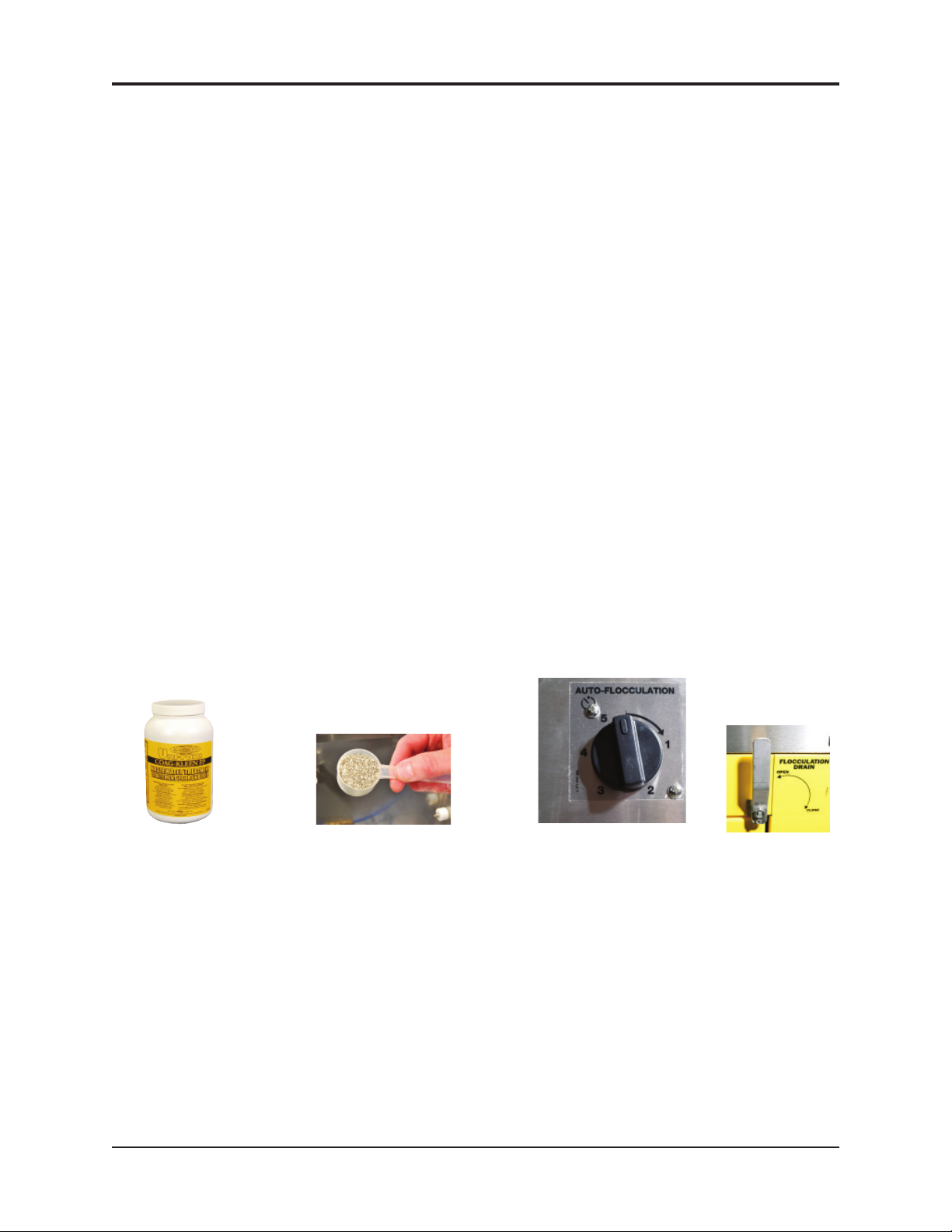
• Remove the Work Screen and the side rails. Sprinkle 2 full scoops* of the flocculant, COAG-KLEEN, even-
ly over the dirty water. The COAG-KLEEN Flocculant is included with your spray gun cleaner. Close the lid
and turn the Flocculation Timer fully. When the Timer is finished wait 2 minutes and turn the timer a second
time to the one minute mark.
• Open the Flocculation Drain Valve, using the Control on the front of the unit to drain and filter the dirty
water. Note: As the flocculation proceeds, the water should become clear. The debris consisting
of paint absorbed into the flocculant will collect in the filters. Clean the tank with the wash gun, wipe off the
screen and rails, reinsert them and then close the drain valve. Ensure that the Air Agitator in the bottom of
the tank lies flat.
• Remove the two filters containing the debris and set aside for about 20 minutes to dry. When the debris is
dry, it should have an "oatmeal like" consistency. The debris should be disposed of according to local environmental regulations.
• If the filtered water is not clean, see the Troubleshooting section.
• The reclaimed water can be reused until it becomes "silky" to the touch and then it should be disposed of
according to local environmental regulations. When adding fresh water, refill until the water reaches the bottom of the filter holder.
• Reuse the filters and replace as required.
* Each scoop = 1 fl oz or 34g of flocculant; 2 kg = about 50-58 scoops.
Co-Ag Floculant
Co-Ag Floculant
Granules
Floculant
Timer
Flocculant Drain
Valve
10

MANUAL - SPRAY GUN CLEANERS - UG5000W SERIES Revision 2019-3
CLEANING OPERATION
CLEANING SOLVENTBORNE SPRAY GUNS IN LEFT SOLVENT TANK
PRE-CLEAN
• Disconnect the spray gun from the air line.
• Remove disposable cup from the spray guns as shown
below in photo on right. Please be advised that
in some jurisdications the cup must be dried before disposal.
• Squirt solvent into the disposable cup adapter, shown in
photo on far right.
• Pull the trigger and allow waste solvent to drain into
a waste container (not supplied).
• Do not mix water and solvent waste.
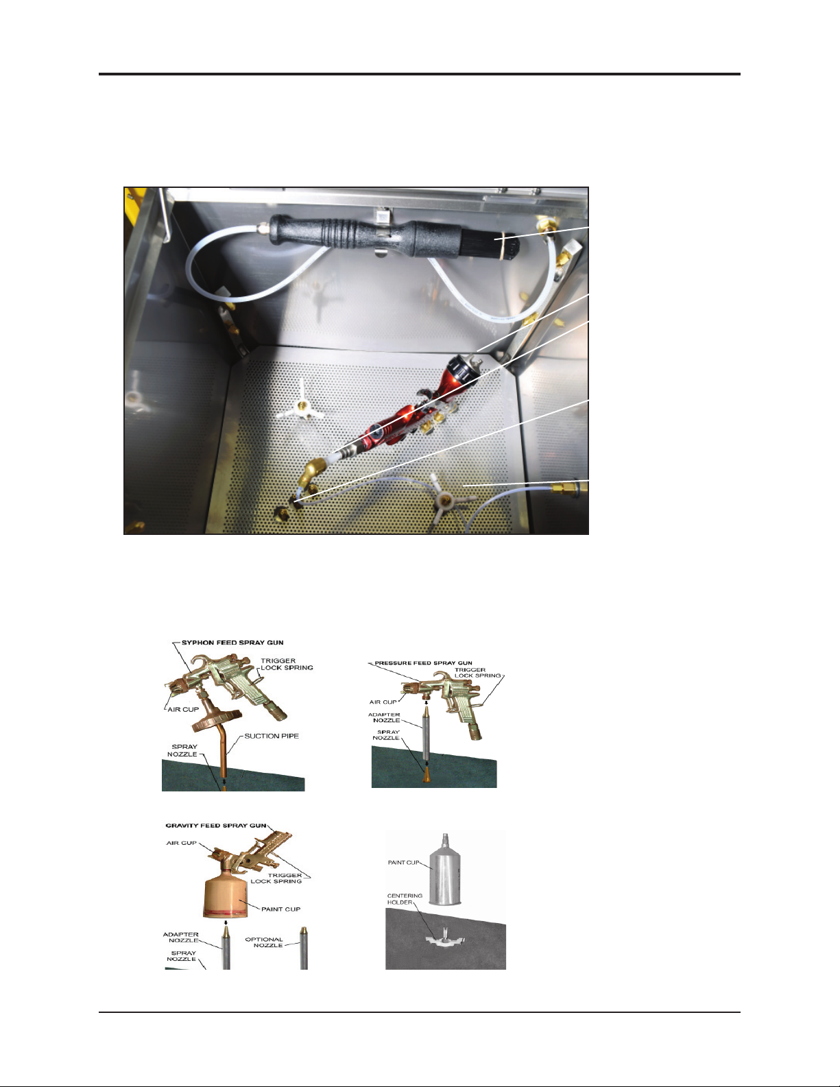
SELECT NOZZLE EXTENSION
• The installed nozzle extension in the tank, part 780-3530, photo below, is for a disposable cup
system, not for use with a conventional cup system.
• The chart and photos below describe the use for the push on nozzle extensions.
• Place the nozzle extension on the nozzle in the cleaning tank as shown in the photo, Wash
Tank, on the next page.
780-3530 110-430PPS 110-430
Type of
Spray Gun
Mount Fixed in tank Push-on Push-on
Length (") 2.5 7.5 8.0
Included in
Spray Gun
Cleaner
Most Disposable
Cup Systems
with larger
openings.
Yes Yes Ye s
780-3530 110-430
110-430PPS
Same nozzle as 780-3530 for
use with disposable cup systems and conventional cup
systems with a large opening.
Conventional
Cup System
with Narrow
Opening.
11

MANUAL - SPRAY GUN CLEANERS - UG5000W SERIES Revision 2019-3
INSTALLING SPRAY GUNS INTO WASH TANK
• Loosen the air cap of the spray gun 2 turns.
To lock the trigger in the open position:
• Use the Trigger Lock Spring as shown in photo. See photo below.
Remove
Gauge
Trigger Lock Spring
Trigger Lock Spring
On Spray Gun
To prevent solvent from entering the air passage way of your
spray gun select one of the following methods suitable for your gun:
• Attach the knurled nut that is attached to the trigger clamp
chain or insert the white plastic plug into the air inlet of the
spray gun as shown in the photo.
Air Plug inserted into the Air
Passage way of the spray gun
• Place the spray gun on a nozzle extension in the wash tank with the air cap facing the corner. See
photo below and on the next page.
12
Placing Spray Gun on
Nozzle Extension
MANUAL - SPRAY GUN CLEANERS - UG5000W SERIES Revision 2019-3
WASH TANK
Brush
Cap points towards corner
Place white plug on
the air fi tting
Place Nozzle extension
on this nozzle
DIFFERENT TYPES OF SPRAY GUNS
Place Conventional
Cup on the 3 prong
fi xture
NOTE: THE
PICTURES
APPLY ONLY
TO THE
SOLVENT SIDE
(LEFT TANK).
13
MANUAL - SPRAY GUN CLEANERS - UG5000W SERIES Revision 2019-3
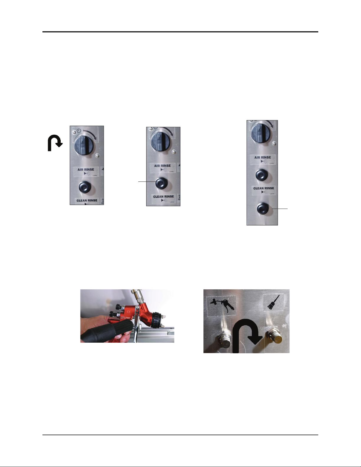
CLEANING CYCLE
• Close the lid of the spray tank and turn the "Auto Wash Timer" clockwise to start cleaning as in photo below.
The wash cycle takes about 60 seconds. Solvent flows from the wash pail.
• Push and hold the "Air Rinse" button for about 2 seconds to evacuate the wash solvent. See photo below.
• Press and hold the "Clean Rinse" buttom for about 2 seconds to send 100 cc of clean solvent through the jets
to rinse the the spray guns, see the photo below. Clean-rinse is limited to 100 cc to minimize clean solvent
consumption. Wait 30 seconds for the Rinse Pump to fully recharge before re-pressing the Clean Rinse button.
Push and hold the "Air Rinse Control" button for about 2 second to air-rinse the guns.
•
After cleaning the spray guns, remove the guns and cups from the tank and wipe them dry. Do not
store spray guns and cups in the wash tank.
PUSH
Timer Air Rinse
Clean
PUSH
Rinse
USING THE FLOW-THROUGH BRUSH
• To deliver wash solvent through the Brush for washing, (see left photo below) step on the foot
pedal.
• Solvent flow is set at the factory but may be adjusted using the "Brush Flow Control".
See the photo below.
• To increase flow, loosen the locking nut, rotate the dial anti-clock wise, then tighten locking nut.
Flow through brush
Flow Control Flow Control
Water Gun Brush
USING CLEAN SPIGOT
14

MANUAL - SPRAY GUN CLEANERS - UG5000W SERIES Revision 2019-3
UG5000EWFS
The spigot is a unique feature of the UG5000EWFS. Step on the Manual Rinse Foot pedal to activate the
clean solvent flow through the spigot to rinse the spray guns.
See photos below.
CLEAN SPIGOT CLEAN
SPIGOT
WASH
BRUSH
MAINTENANCE
LEFT TANK (SOLVENT)
• A removable fi lter screen is installed at the end of the suction pipe, inside the left hand solvent wash
pail. See A photo bellow.
• Once each month, remove the pail from the cabinet, then remove the suctiuon pipe as in B photo
below and clean the metal fi lter in a mixing cup of clean solvent. See photo C below.
Wash Pail
B, Metal Screen Filter
A, Solvent Side Wash Pail
C, Metal Screen
Filter to Clean
15

MANUAL - SPRAY GUN CLEANERS - UG5000W SERIES Revision 2019-3
REPLACING SOLVENT IN PAILS (FOR LEFT SOLVENT TANK)
Replace the solvent when the solvent in the solvent wash tank has lost cleaning effectiveness or after approximately 100 cleanings.
• Remove the Rinse Pump from the clean solvent rinse pail and move this pail out of the cabinet. .
• Close the drain valve, (horizontal position) as in the photo A below. Remove the drain hose, and
suction pipe from the wash pail. See photo B and C.
• Remove the solvent wash pail from the cabinet. Pour the wash solvent into the waste drum.
See PAIL SET UP under SET UP for procedure to fi ll pails. Fill solvent wash pail with 16 L
Drain Valve
Suction Tube and
Filter
Hole for Drain
hose
Wash Pail
16
MANUAL - SPRAY GUN CLEANERS - UG5000W SERIES Revision 2019-3
PROBLEM REASON CORRECTIVE ACTION
Drain valve closed
Open drain valve (put in vertical
position), if not already open
Liquid level too low
Check wash liquid level. Add liquid if
less than1/2 full.
Fill to 4 gal (11 L).
Debris in pump or suction and
output hose
Follow Procedure 1, "Blocked Fluid
Passage in Diaphragm pump" in the
next section.
Water or contaminants are in
air line of pump.
Passage in Diaphragm Pump" in the
next section.
Flow Control is closed.
Manual flow control is loc ated on the
control panel on the front of the
machine. Loosen the locking nut and
rotate control to the left to increase
flow.
Liquid level too low
Check wash liquid level. Add liquid if
less than 1/2 full up to 4 gal (11 L).
Foot pedal switch not
functioning
Inspect foot switch for free travel, and
lubricate with gun oil. If switch will
not travel freely, replace with PN 155400BF2
Water in air line causes pump
to stall
Follow Procedure 2. "Blocked Air
Passage in Diaphragm Pump" in the
next section.
WASH PUMP DOES NOT
STOP UNLESS TIMER IS
TURNED BY HAND OR AIR IS
SHUT OFF. WASH PUMP
DOES NOT START.
Defective Timer
TIMER KNOB SPINS BACK
WHEN TURNED
Defective Timer Replace Timer. PN 115-200K.
Replace Timer, PN 115-200K.
WASH PUMP MAKES
HISSING SOUND AND LIQUID
DOES NOT FLOW
BRUSH PUMP DOES NOT
MAKE A NOISE AND LIQUID
DOES NOT FLOW W ITH
PEDAL DEPRESSED
Brush is clogged with debris.
Unthread brush from hose and
operate foot pedal. If free solvent flow
is now seen, replace brush with PN
144-390S
WASH PUMP MAKES
PUMPING SOUND BUT
LIQUID DOES NOT FLOW
FROM THE JE TS
of fresh solvent. Top up clean solvent pail to 19 L. Insert the Rinse Pump into the full clean
solvent pail. Return hoses to the Wash Pail and return both pails to the cabinet.
TROUBLESHOOTING CHART
17

MANUAL - SPRAY GUN CLEANERS - UG5000W SERIES Revision 2019-3
Trouble shooting continued
SYMPTOM REASON CORRECTIVE ACTION
INSIDE WALL OF TANK IS
COATED WITH PAINT EVEN
THOUGH OPERATOR
MA INTAINS TANK
Liquid lacks cleaning strength
Replace solvent / water and AQUAKLEEN in pail. Consider a solvent
that is formulated for type of paint
used and for use with automatic
spray gun cleaning.
Trigger not locked in open
position
Use Trigger Lock Spring PN 120-350
Spray gun is not properly
installed on to nozzle
Re-install with proper adapter
Incompatible solvent
pp
solvent formulated for type of paint
Low pressure in air supply
p
of 85 PSI
Plugged jets
yg
through the jets. If not successful,
SOLVENT APPEARS RED or
ORANGE
Water in solvent is corroding
metal pail
Replace or recycle wash solvent
GUNS NOT CLEAN, WASH
SOLVENT IS MILKY WHITE
Wash solvent is c ontaminated
with water
Replace or recycle wash solvent
Not enough liquid in clean
rinse pail (right side)
Add liquid
Rinse Pump is leaking from a
crack caused by corrosion
due to acidic or chlorine
contaminated solvent
Replace rinse pump, PN URP-100SF
Faulty Valve
CLEAN RINSE IS DIRTY
Replace Combination Valve, PN
UVB-400KIT
GUNS NOT CLEAN, PUMP
WORKING, SOLVENT FLOW
NORMA L
CLEAN RINSE DOES NOT
WORK
18

MANUAL - SPRAY GUN CLEANERS - UG5000W SERIES Revision 2019-3
(4" UDP4TA Pump shown but procedures are the same for the
2" UDP2TAB Pump)
PROCEDURE 1
Blocked Fluid Passage In Diaphagm Pump
If the pump sounds like it is working but liquid does not flow,
clear the fluid passage as follows:
• Remove suction tube from the pail and blow air at 85 PSI
into the INLET Sovent Hose (see diagram). Step on foot
4" pump
pedal. This procedure may have to be repeated several times.
If this procedure does not help, blow some water into the
suction hose using a spray gun, wait one minute and step on
foot pedal. This procedure may have to be repeated several
times. If this procedure does not work, the pump must be
replaced.
If you need to replace the pump log-on to Service Channel and
Fixxbook or call the Uni-ram Service Engineer. The warranty on
the diaphragm pump is two years from date of purchase.
This procedure will also clear a blockage in the fluid line for
the wash gun.
2" pump
PROCEDURE 2
4" pump
Blocked Air Passage In Diaphragm Pump
If there is a steady hissing sound and the pump is not cycling, the spool
valve has stalled due to a blocked air passage. Follow the procedure below
to clear the blockage.
• Connect a blow gun to an 85 PSI source. Locate the blue hose that
extends from the air exhaust port of the diaphragm pump. Use a
blow gun to blow air into the open end of this hose. Turn timer. If
the procedure is successful, the pump will start working. The procedure may have to be repeated several times. If this procedure does not work, replace
the pump.
• Cause: Contaminants in the air supply (water, oil, solid particles etc)
• Preventative Action: If necessary, install an Airline (Moisture) Filter.
PROCEDURE 3
2" pump
Blocked Passage in Air Line
The components in the air line are the diaphragm pump, air valve, foot pedal, 3-way ball valve and regulator.
See the Flow Diagram and the section: Replacement Parts.
To troubleshoot a component:
1) Disconnect the air line to the component using the quick disconnect.
2) Step on foot pedal and check for presence of positive air pressure in the air line. If there is ample positive air
pressure, replace the component.
If air pressure is absent, there is a faulty component upstream. Reconnect the air line and check the operation of
the next component upstream by following steps 1 and 2 above.
19

MANUAL - SPRAY GUN CLEANERS - UG5000W SERIES Revision 2019-3
FLOW DIAGRAM
41EETCQ
6X4TYN
"63
6X4TYN
"41"43
"39
6X4TYN
6X4TYN6X4TYN
"63
6X4TYN
"63
"63
8X6TYN
"71
"62
6X4TYN
ENILPIHW
ISP51
RO-MM6TRU
"05
ISP02-51ROFTES
LORTNOCWOLF
A0593-201#
"75
"01
ROTCIRTSERRIA
ISP05TES
1653-201
"4
"5.2
"11
TP5H41FCQ
"71
"22
6X4TYN6X4TYN
Shows the flow of solvent and compressed air.
FLOW DIAGRAM FOR UG5000W
"92"92
"3
6X4TYN
"3
TNEMEGNARRA
"71
NOITATIGARIA
"3
"A"WEIV
6X4TYN
"3
"3
6X4TYN
"71
"3
"23
"3
"8
"41
"21
"01
"21
8X
6TYN
"04
OI
6111X83HBR
81X233TYN
6111X83HBR
"63
"42
"12
"5
2
"53
"33
"85
"85
"51
TUORIA
"12
NIRIA
"46
UG5000EW:
The ow diagram for UG5000EW is the
same as the above except that the pail
set for UG5000EW includes a over ow
pipe and riser for use with a solvent
recyler.
MARGAIDWOLF
L-W0005GU-DF
:ETAD.VER
8102-92-YAM
"22
"21
"34
"43
"82
RT21X41HBR
20

MANUAL - SPRAY GUN CLEANERS - UG5000W SERIES Revision 2019-3
Shows the flow of solvent and compressed air.
FLOW DIAGRAM FOR UG5000EWFS
21

MANUAL - SPRAY GUN CLEANERS - UG5000W SERIES Revision 2019-3
22

MANUAL - SPRAY GUN CLEANERS - UG5000W SERIES Revision 2019-3
23

MANUAL - SPRAY GUN CLEANERS - UG5000W SERIES Revision 2019-3
24
MANUAL - SPRAY GUN CLEANERS - UG5000W SERIES Revision 2019-3
25
MANUAL - SPRAY GUN CLEANERS - UG5000W SERIES Revision 2019-3
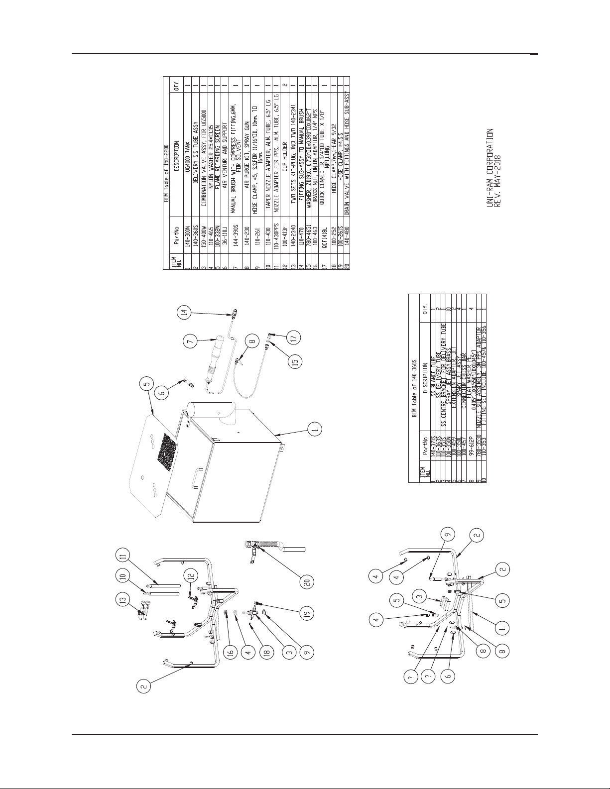
REPLACEMENT PARTS
DESCRIPTION Part Number
FLOW-THROUGH BRUSH, SOLVENT 144-390
FLOW-THROUGH BRUSH, WATER 144-390W
2" DIAPHRAGM PUMP (WATERBORNE SIDE) UDP2TAB
4" DIAPHRAGM PUMP (SOLVENT SIDE AND BRUSH) UDP4TA
AIR BLOW GUN 102-7010
WASH GUN 102-7020
TIMER KIT 115-200/K
VALVES (PEDAL,RINSE ETC) 115-400BF
NOZZLE EXTENSION, CONVENTIONAL SYSTEMS ONLY 110-430
NOZZLE EXTENSION, ALL MODELS, PUSH ON 110-430PPS
NOZZLE EXTENSION, DISPOSABLE CUP SYSTEMS ONLY 780-3530
TRIGGER CLAMP & PLUG KIT 140-2340
AIR PASSAGE PLUG 140-230
LID SWITCH 115-350F
WASH PAIL 150-8111P
RINSE PAIL 150-8114P
LID FOR WASH OR RINSE PAIL 780-8113
PAIL, WATERBORNE (OPEN TOP) 102-8111P
GROUND WIRE 600-8901
WHIP LINE AND COUPLER 102-3980T
PAINT CAP HOLDER 100-413F
FILTER BAG, PRIMARY 102-8125
FILTER BAG, SECONDARY 102-8126
FILTER HOLDER 102-8120
AIRLINE MOISTURE FILTER 10-220
FILTER PAD, REGULAR, 13.75 X 17.5", PKG OF 10 FP6500-10
COAG KLEEN 102-8300
AQUA-KLEEN 102-8200
26

MANUAL - SPRAY GUN CLEANERS - UG5000W SERIES Revision 2019-3
144-390, FLOW-THROUGH
BRUSH ASSY (INSIDE)
140-361F, DELIVERY TUBE ASSY
110-356, TAPER NOZZLE
SHOWN)
140-450, DELIVERY TUBE
CENTER CONNECTOR ASSY
WITHOUT JETS
100-350, SPRAY JETS
FP6500-1, FILTER PAD
10-171, TANK
DRAIN VALVE
140-421F, QC NIPPLE
SOLVENT (LEFT) TANK
WATER (RIGHT) TANK
120-318, HANDLE
140-332N, FLAME
RETARDANT SCREEN
110-351, DELIVERY TUBE
PLATE HOLDER
140-450, DELIVERY TUBE
CONNECTOR ASSY
120-020PR, AIR
INLET WITH
PRESSURE
REGULATOR (NOT
140-400F, COMBINATION
VALVE (NOT SHOWN)
Work Screen, 102-3030
AIR AGITATION SYSTEM
Filters
Primary, 400
Micron, 102-8125
Secondary, 25
Micron, 102-8126
Filter Holder,
102-8120
Wash Pail,19L,
102-8111P
Air Agitator, 102-3580
Drain Hole (Shut Off
Valve underneath, not
shown)
27

MANUAL - SPRAY GUN CLEANERS - UG5000W SERIES Revision 2019-3
Full Product Warranty
These Uni-ram products have been engineered and manufactured to high performance standards.
Each unit has been subjected to detailed factory testing before shipment.
This product comes with a one-year full warranty from the date of purchase. Uni-ram Corporation
reserves the right to repair or replace the unit, free of charge, to the original purchaser if a part is found
to be defective in material or workmanship as determined by factory service personnel. The items
listed below under "Conditions of Warranty" as consumables are not covered.
Uni-ram reserves the right to direct the customer to ship the unit collect to the Uni-ram factory or to an
approved Service Center for repair using the Uni-ram Return Goods Procedure or to repair the unit onsite. To prevent damage in transport, the purchaser must ship the unit in the original packaging or use
alternate adequate packaging. All units must be shipped clean and free of liquid.
Diaphragm Pump:
We are pleased to advise that the warranty on the diaphragm pump, the heart of the spray gun
cleaner, comes with a 2 year replacement warranty. If, in the unlikely event your diaphragm pump fails
during the first two years of service, call Uni-ram Service at 1-800-417-9133. We will send you a new
pump free of charge and arrange for the return of your original pump.
Conditions of Warranty:
As Uni-ram Corporation has no control over the working conditions or circumstances under which the
purchaser stores, handles or uses the product, Uni-ram makes no warranty or claim, either expressed
or implied with respect to this product's fitness for any purpose or the result to be obtained from its
use. This condition applies to the sale of all products and no representative or distributor of Uni-ram
Corporation has the authority to waive or change these conditions.
This warranty applies only to the original purchaser and does not apply if the unit has been misused,
overloaded, neglected, altered or used for any purpose other than those specified in the operating and
installation instructions. Deterioration due to normal wear is not covered by this warranty. Damage due
to accident, transportation, fire, floods or acts of God is also not covered. Units whose serial numbers
have been altered or removed are not covered. The warranty is invalid if unauthorized chemicals as
noted in the manual or liquids with acid content are used in this unit. Unauthorized attempts at selfrepair or alterations by the owner also invalidate this warranty. Interior or exterior finishes are not covered by this warranty.
Consumable Items are not covered by this warranty (eg: gaskets, screens, bags, filters, nozzles and
air jets).
This warranty replaces all other warranties expressed or implied by statute or otherwise.
To make a claim, call Uni-ram Service at 1-800-417-9133 and quote the serial number of the unit.
28
 Loading...