

Unique Appliances UGP30CRRHT, UGP30CRRHRB, UGP30CRRHW, UGP30CRRHLG INSTALLATION INSTRUCTIONS AND OPERATION MANUAL

CLASSIC RETRO BY UNIQUE
30” RANGE HOOD
UGP-30CR RH W, UGP-30CR RH T,
UGP-30CR RH LG, UGP-30CR RH RB
MODEL NUMBERS:
OWNER’S GUIDE
serial number:
DEC20V1

TABLE OF CONTENTS
SAFETY NOTICE . . . . . . . . . . . . . . . . . . 03
PRE INSTALLATION . . . . . . . . . . . . . . . . 06
NECESSARY TOOLS . . . . . . . . . . . . . . . . 08
PARTS INCLUDED . . . . . . . . . . . . . . . . . 09
PARTS LIST . . . . . . . . . . . . . . . . . . . . . 09
INSTALLATION PROCEDURE . . . . . . . . . . . 10
OPERATING INSTRUCTIONS . . . . . . . . . . . 15
TROUBLESHOOTING. . . . . . . . . . . . . . . . 15
MAINTENANCE . . . . . . . . . . . . . . . . . . . 16
TECHNICAL SPECIFICATIONS. . . . . . . . . . . 17
WIRING DIAGRAM . . . . . . . . . . . . . . . . . 17
PARTS DIAGRAM AND LIST . . . . . . . . . . . . 18
WARRANTY . . . . . . . . . . . . . . . . . . . . . 20
APPLIANCE INFORMATION . . . . . . . . . . . . 22
NOTES . . . . . . . . . . . . . . . . . . . . . . . . 22
PRODUCT REGISTRATION. . . . . . . . . . . . . 22
CONTACT US . . . . . . . . . . . . . . . . . . . . 23
2

SAFETY NOTICES
Approved for residential type units for residential use only read these
instructions and be safe.
Please read these instructions completely before starting.
The installation of the appliance must respect all codes.
Important: Save these instruction so that you can provide the electrical
inspector in your area.
Safety Warning: Turn o the circuit in the electrical panel and lock
front panel to connect the cord of this unit.
Power Requirement: 110V-120V/60HZ
CAUTION: USE THIS PRODUCT FOR GENERAL FAN ONLY. DO
NOT USE THIS PRODUCT TO EXHAUST FUMES OR HAZARDOUS OR
EXPLOSIVE MATERIALS.
WAR NING: TO REDUCE THE RISK OF FIRE, ELECTRICAL SHOCK
OR INJURY TO PEOPLE, OBSERVE THE FOLLOWING:
1. Use this unit only for the purposes intended by the manufacturer.
If you have any questions about this product, contact the
manufacturer.
2. Before the machine’s maintenance or cleaning, turn o the
electrical panel and lock the panel blocking feature to prevent from
accidentally activating the power. If it is not possible to lock the
access panel, attach a highly visible label to the electrical panel.
3. A qualified person should perform the installation and wiring of the
electricity in accordance with all codes and all standards, including
fire resistance rating.
4. When you use hood together with stove, please do not close the
window and door of the kitchen. Because during the fuel stove
working, which will consume lots of air, so do open the door and
window to make the kitchen ventilating, to avoid any suocation.
5. It is important to provide sucient air for proper combustion of
heating equipment and proper evacuation of gases through the
chimney pipe to prevent back flow of air. Follow the instructions and
safety standards of the manufacturers of heating equipment, such as
those published by the National Fire Protection Association (NFPA),
the American Society for Heating, Refrigeration and Air Conditioning
Engineers (ASJRAE) and the code authorities in your area.
6. When cutting or drilling into wall or ceiling, be sure not to damage
electrical wiring or other access to public service.
7. Always evacuate outside the conduit system.
3
SAFETY NOTICES
To reduce the risk of fire and to properly exhaust air, be sure that the
pipe is leading outside, do not exhaust air into the space between the
walls, ceilings, attics, crawl spaces or garages.
WAR NING — GROUNDING INSTRUCTIONS
This device must be grounded. In the event of an electrical short circuit,
grounding reduces the risk of electric shock by providing an escape
wire for the electric current. This appliance is equipped with a cord with
a grounding wire with a grounding plug. The plug must be inserted into
a properly installed and grounded outlet.
CAUTION — INCORRECT GROUNDING CAN CAUSE RISK OF
ELECTRIC SHOCK
If you are unsure whether the device is grounded properly or if the
grounding instructions are not fully understood, consult a qualified
electrician.
Do not use an extension cord. If the power cord is too short, have a
qualified electrician install an outlet near the device.
WAR NING — TO REDUCE THE RISK OF FIRE OR ELECTRIC
SHOCK, DO NOT USE THIS HOOD WITH EXTERNAL SOLID STATE
SPEED CONTROLLERS
WAR NING — TO REDUCE THE RISK OF FIRE, USE ONLY
METAL DUCTS
Install this hood in accordance with all the requirements mentioned.
WAR NING — TO REDUCE THE RISK OF FIRE
1. Never leave the stove unattended when it is at a high temperature.
Boil overs cause smoke and fat that overflows can ignite. Heat the oil
slowly at a low or medium temperature.
2. Always operate the hood when you use the stove to high heat or
when you Flame.
3. Clean ventilating fans frequently. Do not let fat accumulate on the
filters or propellers.
4. Use proper pan size. Always use a pot size appropriate to the stove
element.
5. Do not touch on-working or o-soon bulb, to avoid any thorny.
4

SAFETY NOTICES
WAR NING — TO AVOID INJURING SOMEONE IN A GREASE
FIRE, FOLLOW THE FOLLOWING:
1. SMOTHER FLAMES with a lid to the dimensions of the cooking hobs,
a cookie sheet or other metal tray, then turn o the gas or power
supply of the stove. BE CAREFUL NOT TO BURN YOURSELF. If the
flames do not go out immediately, LEAVE AND CALL THE FIRE
DEPARTMENT.
2. NEVER PICK UP A FLAMING PAN. You could be hurt.
3. DO NOT USE WATER, including Dish towels or wet towels-a violent
steam explosion of dew may be occurred.
4. Use an extinguisher only if:
• You are sure to have a Class ABC extinguisher that you know how
to use.
• The fire is small and confined to the area where it was formed.
• Firefighters were called.
• You can fight against the fire with an exit behind you.
OPERATIVE MODE
Always leave safety grills and filers in place. Without the presence of
these blowers could catch hair, fingers or clothing. The manufacturer is
not liable if detailed in this manual for installation info, maintenance and
proper use of the product are not observed. The manufacturer declines
all responsibility for any injury caused by negligence. This product is
manufactured for internal use. Do not use this appliance outdoors.
5

PRE INSTALLATION
CAUTION
Due to the weight and size of these vent hoods and to reduce the
risk of personal injury or damage to the product, TWO, TO THREE
PEOPLE ARE REQUIRED FOR PROPER INSTALLATION.
• Please read the instructions carefully. Unpack the range hood
and check that all functions are working before installing.
• Ensure that the voltage (V) and the frequency (Hz) indicated on
the sticker match the voltage and frequency at the installation site.
• Check that the area behind the installation surface to be drilled is
clear of any electrical cables or pipes, etc.
• The surfaces of the range hood are very easily damaged during
installation if scratched or bumped by tools. Please take care to
protect the surfaces during installation.
• Protect the cooktop surface below with cardboard, or the like, to
prevent damage.
• The manufacturer shall not be held liable for consumer’s failure
to observe and follow all pre-installation procedures and safety
regulations.
• The vertical distance from the cooking surface to the bottom of
the range hood should be at least 24” to 36” for best performance.
• Determine if your installation will be top venting or back venting,
and ensure that the openings in the cabinet or wall are in the
appropriate locations and appropriate size.
• If this is a new installation, choose the venting method that suits
your needs. Cut out openings for the damper and for power
access in the cabinet bottom or exterior wall, depending on the
installation method chosen.
6
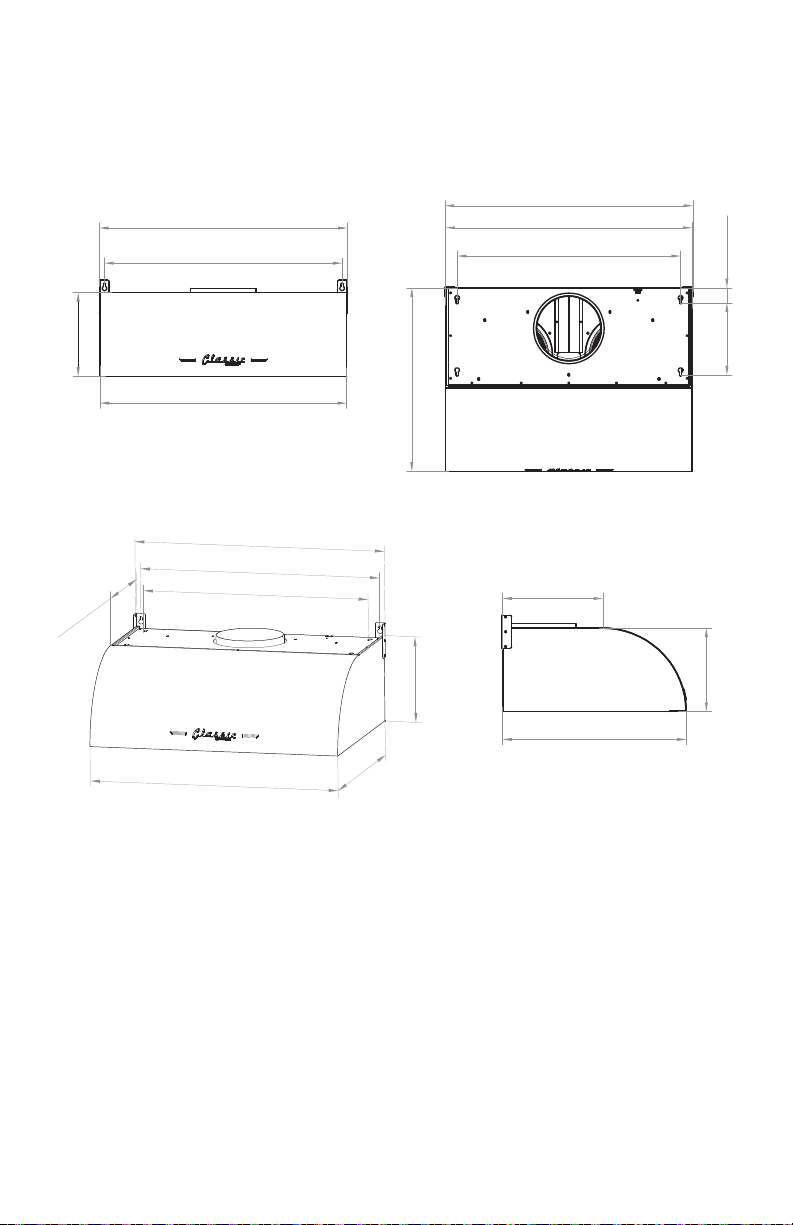
750 mm (29.5”)
723 mm (28.5”)
558.8 mm (22”)
755 mm (29.75”)
254.3 mm (10”)
254.3 mm (10”)
305 mm (12”)
558.8 mm (22”)
254.3 mm (10”)
305 mm (12”)
MEASUREMENTS
PRE INSTALLATION
Front View Top View
755 mm (29.75”)
723 mm (28.5”)
254.3 mm (10”)
750 mm (29.5”)
558.8 mm (22”)
3/4 View
755 mm (29.75”)
305 mm
(12”)
723 mm (28.5”)
680 mm (26.75”)
254.3 mm (10”)
755 mm (29.75”)
750 mm (29.5”)
680 mm (26.75”)
45.8 mm (1.75”)
220 mm (8.75”)
Side View
305 mm (12”)
254.3 mm (10”)
558.8 mm (22”)
750 mm (29.5”)
558.8 mm (22”)
7
PRE INSTALLATION
DUCT PLANNING
• The ventilation hood is equipped for 8” round ducts. This hood can
be ventilated vertically through the top cabinet or ceiling. A duct
transition piece is provided for vertical exhaust. You can use elbows
(sold separately) to ventilate horizontally through the rear wall.
• Determine the exact position of the hood.
• Plan the route to vent the ventilation duct to the outside.
• Use the shortest and straightest path possible. For satisfactory
performance, the length of the duct should not exceed 12.5 feet of
equivalent length for all duct confi gurations.
• Use only metal ducts.
WALL FRAMING FOR ADEQUATE SUPPORT
WAR NING
THESE VENT HOODS ARE HEAVY. ADEQUATE STRUCTURAL
SUPPORT IS REQUIRED.
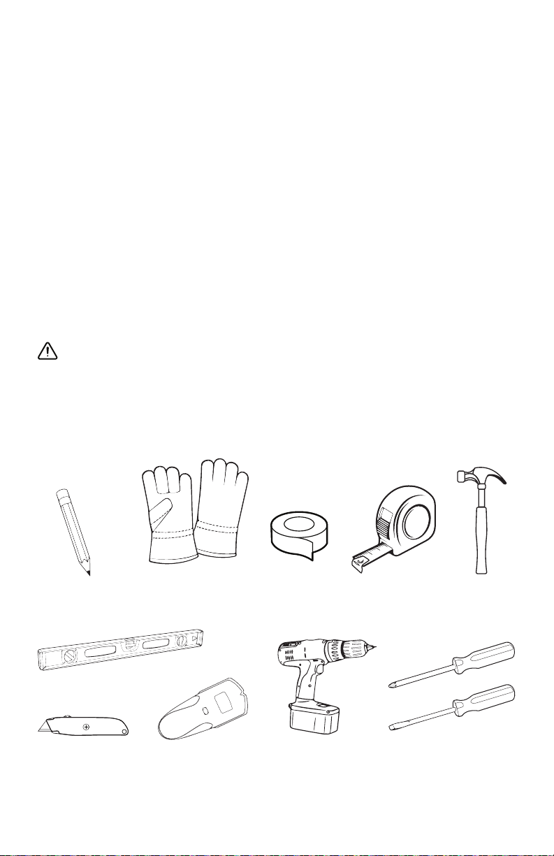
NECESSARY TOOLS
Marker or
pencil
Level
Utility knife Stud fi nder
Safety Gloves
8
Aluminum
Foil Tape
Powered
screwdriver or
drill
Measuring
tape
screwdrivers
Hammer
Flat-blade
and Phillips
 Loading...