

Uniq UC-610, UC-610CL User Manual
UNIQ
UC-610/UC-610CL
Color Digital CCD Camera
User's Manual
091-0611 V.1.4
09-23-05

1
Table of Contents
Warning ................................................................................................................. 2
Precautions ............................................................................................................ 2
Limited Warranty ................................................................................................... 2
1. Introduction ....................................................................................................... 3
2. Camera Setup ..................................................................................................... 5
3. Camera Functions .............................................................................................. 5
4. RS-232C Communication Control ...........................…........................................ 10
5. Digital Interface Timing ..................................................................................... 12
6. Camera Functional Timing ................................................................................. 13
7. Camera Accessories ……………….............….......................................................... 15
8. Camera Malfunction .......................................................................................... 16
9. Technical Support Information .......................................................................... 17

2
WARNING
TO PREVENT FIRE OR ELECTRIC SHOCK HAZARD,
DO NOT EXPOSE THIS CAMERA UNIT TO RAIN OR MOISTURE.
DO NOT ATTEMPT TO REMOVE CAMERA COVER OR MODIFY THE CAMERA UNIT,
WARRANTY WILL BE VOIDED.
PRECAUTIONS
Do dot attempt to disassemble, modify, or repair the camera. Contact UNIQ for help.
Do not point the camera at bright objects, such as the sun, for a long period. It may
cause CCD blooming and permanent damages.
Do not operate the camera beyond the temperature range. Avoid using the camera
above 90% humidity.
Do not use unregulated power supply source.
Do not touch CCD glass cover with fingers or any hard objects other than professional
glass cleaning solvents.
Limited Warranty
UNIQ warrants to the original customer to be free from defects in material and
workmanship for two full years from the date of original purchase. This warranty covers
failures or damages due to defects in material or workmanship, which occur during
normal use. It does not cover damages or failures, which result from shipment,
mishandling, abuse, misuse, or modification.
A Return Material Authorization (RMA) number is required prior to returning any UNIQ
product for repair or replacement.
This proprietary document may not be reproduced or photocopied without the consent of
UNIQ. UNIQ makes no warranty or assumes no responsibility for any errors, which may
appear in this document. UNIQ reserves the right to make changes without notice or
obligation.
For immediate technical assistance, please call (408) 330-0818 or email to
tech@uniqvision.com
3
1. Introduction
1.1 General Description
The UC-610/UC-610CL is a high frame rate, color digital CCD camera using progressive scanning
interline-transfer technology with R, G, B primary color mosaic filters (Bayer arrangement). A
frame grabber collects digital, raw data and displays color images by software conversion. This
color camera is useful for applications where color, high frame rate and high speed are required.
With the asynchronous capture control, high speed moving objects can always be captured. The
square pixels are especially suitable for processing, measuring, and analyzing tasks. This compact
and lightweight camera offers excellent signal to noise performance. It’s compatible with most
popular frame grabbers in the market. The “user-friendly” RS-232C interface control allows users
to control all camera functions without physically touching the camera.
1.2 Features
• 1/3” Progressive scan CCD imager
(R, G, B primary color mosaic filters)
• 659 x 494 active pixels
• 10-bit RS-644 (LVDS)/Camera Link output
• Full frame shutter (1/110 ~ 1/110,000 sec.)
• <56 dB
• Asynchronous reset at full frame shutter
• 110 Hz frame rate
• 40 MHz pixel clock
• RS232C interface control
• C-mount lens
1.3 Applications
UC-610/UC-610CL applications include machine vision, automated inspection, motion capture and
analysis, medical imaging, biomedical imaging, non-contact measurement, and other scientific and
industrial applications where color image and high frame rate are needed.
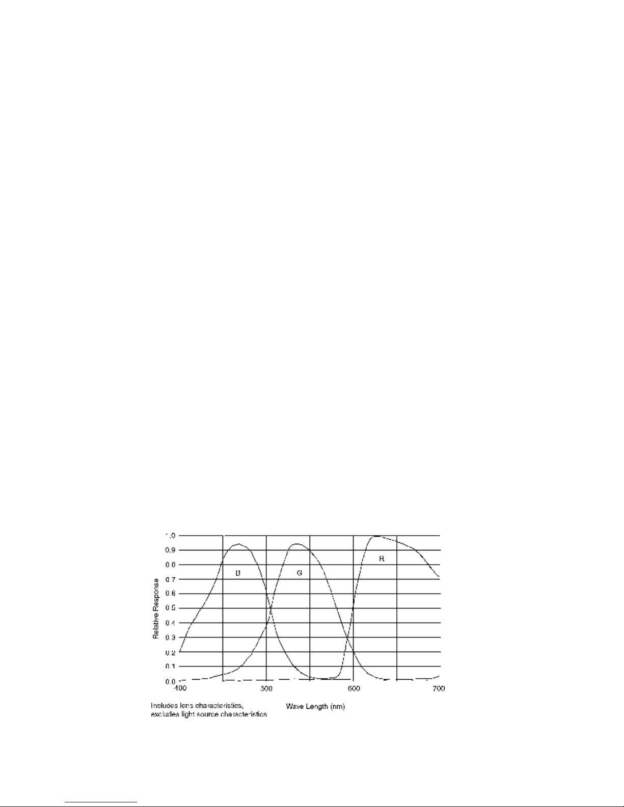
1.4 CCD Imager Spectral Response Curve
4
1.5 Camera Specifications
Model
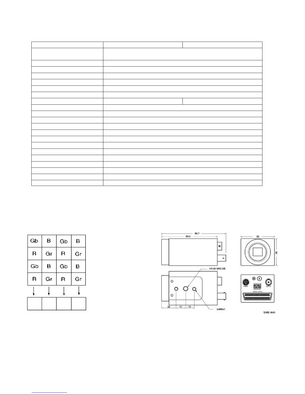
The bottom left pixel is the first
signal output
UC-610 UC-610CL
CCD Sensor 1/3” Progressive scan CCD
(R, G, B primary color mosaic filters)
Chip Size 5.79 mm x 4.89 mm
Effective Pixels (H x V) 659 x 494
Unit Cell Size (H x V) 7.4 µm x 7.4 µm
Pixel Clock 40 MHz (80 MHz for master clock)
Frame Rate 110 fps
Sync. HD: 55.6 KHz; VD: 110.0 Hz
Digital Video Output 10-bit RS-644 Camera Link Format
Analog Video Output 1 V p-p, 75ohm (BNC or 12 pin Hirose)
S/N Ratio <56 dB
Min. Illumination 3 lux
Gain MGC
Gamma 1.0
Electronic Shutter 1/110 ~ 1/110,000 selectable
Lens Mount C-Mount
Operating Temperature
Power Requirement 12V DC, 280 mA, 3.4 W
Dimension 50mm x 39mm x 83mm
Ext. Sync. Internal/External Auto Switch
Asynchronous Reset Standard
Weight 200 g
-10 °C ∼ +50 °C
1.6 Color Coding Diagram 1.7 Camera Dimension
5
2. Camera Setup
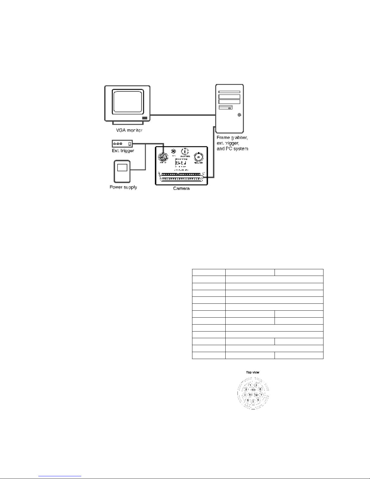
A basic camera and frame grabber system setup, as shown in Figure 1 below, requires a UC610/UC-610CL camera, a standard C-mount lens, a PS-12C power supply or equivalent, a PC
system and a VGA monitor, a frame grabber, and an external trigger device if necessary.
Figure 1. Camera and Frame Grabber System Setup
3. Camera Functions
3.1 12-Pin Connector
The 12-pin Hirose connector is located on the
rear panel of the camera. All ground signals
on pin 1, 3, 5, and 8 are common grounds.
+12 V DC input is recommended on pin 2, but
this camera should withstand +12 V ± 1V
input voltage. Make sure to set the NM/AM
switch to NM position for external HD and VD
locking. For HD (pin 6) and VD (pin 7)
inputs, TTL signals are required (see section
6.6 for details). For asynchronous capture
(VINT) applications, refer to section 6 for
details. For RS-232C interface control via this
12-pin connector, use pin # 10 and #12.
Figure 2 below shows a top view of the 12-pin
Hirose connector.
Pin No. UC-610 UC-610CL
1 GND
2 +12V DC input
3 GND
4 Video
5 GND
6 External HD N/C
7 Ext. VD/VINT N/C
8 GND
9 N/C
10 RX (RS-232C) N/C
11 Integration control
12 TX (RS-232C) N/C
Figure 2. 12-Pin Hirose Connector
 Loading...