


F701-C
WEIGHING CONTROLLER
OPERATION MANUAL
01 Apr. 2015
Rev. 1.16

INTRODUCTION
WARNING
CAUTION
Thank you very much for purchasing our Weighing Controller F701-C.
For good performance, and proper and safe use of the F701-C, be sure to read this instruction
manual and properly understand the contents of it before use. Also, carefully keep this instruction
manual so that it can be referred to at any time.
SAFETY PRECAUTIONS
For safety reasons, please read the following safety precautions thoroughly.
In order to have an F701-C Weighing Controller used safely, notes we would like you to surely
follow divide into " " and " ", and are indicated by the following
documents. Notes indicated here are the serious contents related to safely. Please use F701-C after
understanding the contents well.
INTRODUCTION
WARNING
This sign forewarns the presence of hazards that could result in serious injury or
fatality when incorrectly handled.
CAUTION
This sign forewarns the presence of hazards that could result in personnel injury or
property damage when incorrectly handled.
I

SAFETY PRECAUTIONS
This sign forewarns the presence of hazards
that could result in serious injury or fatality
when incorrectly handled.
Warning on design
Warning on installation
Warning on wiring
WARNING
● For the entire system to function safely when the F701-C becomes faulty or malfunctions,
provide a safety circuit outside the F701-C.
● Before using the F701-C as described below, make sure to consult with our sales personnel.
- Use in environments not described in the operation manual.
- Use greatly impacting human lives and assets, such as medical devices, transport devices
entertainment devices, and safety devices.
● Do not disassemble, repair, or modify the F701-C. Doing so may cause a fire or an electric
shock.
● Do not install in the following environments.
- Places containing corrosive gas or flammable gas.
- Where the product may be splashed with water, oil or chemicals.
● Do not connect a commercial power source directly to the signal input/output terminals.
● Be sure to ground the protective ground terminal.
● The attached AC cable is designed for domestic use in Japan, and its rating is 125V AC, 7A.
For use at voltages exceeding the rating and for overseas use, have a separate AC cable
prepared.
● Before performing the following, make sure that no power is applied.
- Attachment/detachment of connectors of options, etc.
- Wiring/connection of cables to the signal input/output terminals.
- Connection of the earth cable.
● For connection to the signal input/output terminals, check the signal names and pin
assignment numbers, and then carry out wiring properly.
● Be sure to use crimp contacts for connection to the terminal blocks, and do not to connect
bare wires as they are.
● After wiring, be sure to mount the attached terminal block cover. Otherwise, it may cause an
electric shock.
● Do not connect anything to unused terminal(s).
● Before applying power, carefully check the wiring, etc.
II

SAFETY PRECAUTIONS
This sign forewarns the presence of hazards
that could result in serious injury or fatality
when incorrectly handled.
Warning during startup and maintenance
This sign forewarns the presence of hazards
that could result in personnel injury or property
damage when incorrectly handled.
Caution on installation
WARNING
● Use a power supply voltage and load within the specified and rated ranges.
● Do not damage the power cord. Doing so may cause fire or electric shocks.
● Do not touch any signal input/output terminal while applying power. Doing so may cause
electric shocks or malfunctions.
● If the cover of the main body is opened, it may cause an electric shock internally. Even if the
power is off, the internal capacitor is charged. Contact us for internal inspection or repair.
● In the case of smoke, an abnormal smell or strange sound, immediately turn off the power,
and disconnect the power cable.
● Lithium battery use in the F701-C unit.
type: CR14250SE manufactured by Sanyo Electric, or equivalent
Voltage: 3 volts
Capacity: 850 mAh
CAUTION
● Use the F701-C as it is incorporated in a control panel, etc.
● Do not install in the following environments:
- Locations where temperature or humidity exceeds specifications;
- Locations subjected to drastic temperature fluctuations or icing and condensing;
- Outdoors or locations above 2,000m;
- Locations exposed to direct sunlight;
- Locations subject to dust accumulation;
- Locations with poor ventilation;
- Locations with a lot of salt and metal powder;
- Locations where the main unit is subject to direct vibration and shock.
● Take adequate shielding measures when using at the following locations.
- Near a power line.
- Where a strong electric field or magnetic field is formed.
- Where static electricity, relay noise or the like is generated.
● Install the F701-C as far away from devices generating high frequency, high voltage, large
current, surge, etc., as possible. Also, carry out wiring separately from their power lines. Do
not carry out parallel wiring and common wiring.
● Do not use it, broken down.
III

CAUTION
This sign forewarns the presence of hazards
that could result in personnel injury or property
damage when incorrectly handled.
Caution on wiring
Caution during startup and maintenance
Caution during transportation
Caution during disposal
● Tighten the screws for the signal input/output terminals at the specified torque.
If they are loose, shorts, fire or malfunctions may occur.
Tightening torque: 0.5N •m
● For sensors, external inputs/outputs and options, use shielded cables.
● The temporary overvoltage applied to the power should not exceed 1500V.
● For turning on/off the power, be sure to keep intervals of 5 seconds or more.
● After power-on, make sure to warm up the F701-C for at least 30 minutes or more before use.
● If the F701-C is not used by the specified method, its protective performance may be
impaired.
● Maintenance
- When performing maintenance, disconnect the power.
- Do not wipe with a wet rag, or with benzine, thinner, alcohol, etc. Doing so may cause
discoloration or deformation of the F701-C. In the case of heavy contamination, wipe off
the contamination with a cloth after dipping it into a diluted neutral detergent and wringing
it well, and then wipe with a soft, dry cloth.
● When the F701-C is shipped, spacers made of corrugated cardboard are used as
cushioning materials.
Though it is factory-designed so that shocks can sufficiently be absorbed, breakage may
result if shocks are applied when the spacers are reused for transportation. If you send the
F701-C to us for repair, etc., take adequate measures against shocks by using polyurethane
materials, etc., separately.
● If you dispose of the product, handle it as industrial waste.
● Remove the lithium batteries used in the F701-C and make sure to dispose them according
to classification of waste collection.
IV

CONTENTS
CONTENTS
1.APPEARANCE DESCRIPTION .................................................1
1-1.Front Panel .................................................................................................... 1
1-2.Rear Panel ..................................................................................................... 6
2.CONNECTION ............................................................................8
2-1.Load cell Connection ................................................................................... 8
2-1-1.6-wire Connection ........................................................................................ 10
2-1-2.4-wire Connection ........................................................................................ 10
2-1-3.Connecting Load cells in Parallel ............................................................... 11
2-1-4.Sensor Cable ................................................................................................. 11
2-2.Connection of the Power Input Terminals ............................................... 12
2-3.Connection of the Guard Ground ............................................................. 12
2-4.SI/F Connection .......................................................................................... 13
2-5.Connection of the Control Connector ...................................................... 14
2-5-1.Control Connector-Pin Assignment ........................................................... 14
2-5-2.How to Assemble the Connector ................................................................ 15
2-5-3.Equivalent Circuit (Input) ............................................................................. 16
2-5-4.Equivalent Circuit (Output) .......................................................................... 16
3.METHODS OF SETTING .........................................................17
3-1.Setting Procedure ...................................................................................... 17
3-1-1.Method of Selecting a Setting Mode ........................................................... 17
3-1-2.Method of Entering a Setting Value ............................................................ 19
3-2.Setting Mode ............................................................................................... 23
3-2-1.Setting Mode 0 .............................................................................................. 24
3-2-2.Setting Mode 1 .............................................................................................. 26
3-2-3.Setting Mode 2 .............................................................................................. 28
3-2-4.Setting Mode 3 .............................................................................................. 31
3-2-5.Setting Mode 4 .............................................................................................. 33
3-2-6.Setting Mode 5 .............................................................................................. 36
3-2-7.Setting Mode 8 .............................................................................................. 38
4.CALIBRATION .........................................................................41
4-1.Span Calibration ......................................................................................... 41
4-2.Span Calibration Procedure ...................................................................... 42
4-3.Secondary Calibration Procedure (Equivalent Calibration) ................... 43
4-4.Preparation for Calibration ........................................................................ 45
4-4-1.LOCK Release ............................................................................................... 45
4-4-2.Unit ................................................................................................................. 46
4-4-3.Decimal Place ............................................................................................... 46
4-4-4.Capacity ......................................................................................................... 47
V

CONTENTS
4-4-5.Minimum Scale Division .............................................................................. 47
4-4-6.Balance Weight Value .................................................................................. 48
4-4-7.Gravitational Acceleration ........................................................................... 48
4-4-8.1/4 Scale Division ......................................................................................... 50
4-5.Zero Calibration .......................................................................................... 51
4-6.Span Calibration ......................................................................................... 53
4-7.Secondary Calibration (Equivalent Calibration) ...................................... 54
5. FUNCTION SETTINGS .............................................................55
5-1.Display Frequency ..................................................................................... 55
5-2.Subdisplay Selection ................................................................................. 56
5-3.Digital Filter ................................................................................................. 56
5-4.Analog Filter ............................................................................................... 57
5-5.Filter in Stable Condition ........................................................................... 57
5-6.Motion Detection (MD) ............................................................................... 58
5-7.Zero Tracking (ZT) ...................................................................................... 60
5-8.Digital Zero (DZ) ......................................................................................... 61
5-9.Digital Zero Clear ........................................................................................ 62
5-10.Zero Regulation Value ............................................................................. 62
5-11.One-touch Tare Subtraction .................................................................... 63
5-12.One-touch Tare Subtraction Reset ......................................................... 64
5-13.Digital Tare Subtraction ........................................................................... 65
5-14.Restriction of the Tare Subtraction Function ........................................ 66
5-15.Switching Gross Weight/Net Weight Display ........................................ 67
5-16.Reversing Symbol at Discharging Control ............................................ 68
5-17.Invalidation of Function Keys ................................................................. 68
6.DISCHARGING CONTROL MODE ..........................................69
6-1.Feeding Weighing and Discharging Weighing ........................................ 69
6-1-1.Feeding Weighing ......................................................................................... 69
6-1-2.Discharging Weighing .................................................................................. 72
6-1-3.Discharging Mode ........................................................................................ 75
VI
6-2.Simple Comparison Control and Sequence Control ............................... 76
6-2-1.Simple Comparison ...................................................................................... 76
6-2-2.Sequential Control ........................................................................................ 77
6-2-3.Sequence Mode ............................................................................................ 82
6-3.Auto Free Fall Compensation Regulation /
Auto Free Fall Compensation ON/OFF /
Average Count of Auto Free Fall Compensation /
Auto Free Fall Compensation Coefficient ................................................ 83

CONTENTS
6-4.Final / Set Point 2 / Set Point 1 / Compensation / Over / Under ............. 86
6-5.Negative Compensation ............................................................................ 89
6-6.Near Zero / Upper Limit / Lower Limit ...................................................... 90
6-7.Upper/Lower Limit Comparison /
Upper/Lower Limit Comparison Mode /
Near Zero Comparison / Final and Comparison /
Over/Under Comparison Mode ................................................................. 91
6-8.Complete Signal Output Mode / Complete Output Time /
Judging Time / Comparison Inhibit Time / Output Selection 2 .............. 93
6-9.Judging Times / AZ Times / At Start Near Zero Confirmation /
At Start Weight Value Confirmation / Adjust Feeding /
Adjust Feeding Time .................................................................................. 96
6-10.Net Over / Gross Over ............................................................................ 100
6-11.Weight Error / Sequence Error .............................................................. 101
7.STATISTICAL AND ACCUMULATION FUNCTION SETTING AND
OPERATION ...........................................................................102
7-1.Data Display .............................................................................................. 103
7-2.Accumulation Command ......................................................................... 103
7-3.Accumulation Clear .................................................................................. 105
7-4.Auto Accumulation Command ................................................................ 107
8.SYSTEM MODE .....................................................................109
8-1.LOCK (soft) ............................................................................................... 109
8-2.Password .................................................................................................. 109
8-3.Self-Check and Memory Clear ................................................................. 110
9.EXTERNAL INPUT/OUTPUT SIGNALS
(CONTROL CONNECTOR) ....................................................111
9-1.Control Connector-Pin Assignment ....................................................... 111
9-2.Equivalent Circuit (Input) ......................................................................... 112
9-3.Equivalent Circuit (Output) ...................................................................... 112
9-4.External Input Signal ................................................................................ 113
9-4-1.Gross/Net Switching (G/N) <Edge Input> <Level Input> ......................... 113
9-4-2.Digital Zero (D/Z ON) <Edge Input> .......................................................... 113
9-4-3.Tare Subtraction (TARE ON) <Edge Input> .............................................. 114
9-4-4.Tare Subtraction Reset (TARE OFF) <Edge Input> ................................. 114
9-4-5.Hold (HOLD) <Level Input> ........................................................................ 114
9-4-6.Judge <Level Input> ................................................................................... 115
9-4-7.Feed / Discharge <Level Input> ................................................................. 115
9-4-8.Input Signals Used in Sequence Mode ..................................................... 115
VII

CONTENTS
9-4-9.Accumulation command <Edge Input> .................................................... 116
9-4-10.Accumulation Clear <Edge Input> .......................................................... 116
9-4-11.Input Selection .......................................................................................... 117
9-5.External Output Signal ............................................................................. 118
9-5-1.Near Zero ..................................................................................................... 118
9-5-2.Lower Limit, Upper Limit ........................................................................... 118
9-5-3.Stable ........................................................................................................... 118
9-5-4.Weight Error ................................................................................................ 118
9-5-5.Sequence Error ........................................................................................... 119
9-5-6.RUN .............................................................................................................. 119
9-5-7.Accumulation Error .................................................................................... 119
9-5-8.SP1, SP2, SP3 ............................................................................................. 120
9-5-9.Under, Go, Over .......................................................................................... 121
9-5-10.Complete ................................................................................................... 122
9-5-11.Output selection ....................................................................................... 123
10.INTERFACE .........................................................................124
10-1.2-wire Serial Interface (SI/F) .................................................................. 124
10-1-1.Connection ................................................................................................ 124
10-1-2.Auto Print Command ................................................................................ 124
10-2.RS-232C Interface ................................................................................... 125
10-2-1.Communication Specifications ............................................................... 125
10-2-2.Cable .......................................................................................................... 125
10-2-3.Setting Values for RS-232C ..................................................................... 126
10-2-4.Communication Mode .............................................................................. 126
10-2-5.Transmission Format ............................................................................... 128
10-2-6.Communication Format ........................................................................... 129
10-3.BCD Parallel Data Output Interface ...................................................... 137
10-3-1.Control Connector-Pin Assignment ....................................................... 137
10-3-2.Equivalent Circuit (Input) ......................................................................... 137
10-3-3.Equivalent Circuit (Output) ...................................................................... 138
10-3-4.BCD Data Output ...................................................................................... 138
10-3-5.Polarity Output (MINUS) ........................................................................... 138
10-3-6.Over Status Output (OVER) ..................................................................... 139
10-3-7.Print Command Output (P.C) ................................................................... 139
10-3-8.Data Strobe (STROBE) ............................................................................. 139
10-3-9.BCD Data Update Rate Selection ............................................................ 140
10-3-10.Data Hold Input ....................................................................................... 140
10-3-11.Logic Switching Input ............................................................................ 140
10-3-12.Output Selection Input ........................................................................... 140
10-4.D/A Converter ......................................................................................... 141
10-4-1.Name of Each Part .................................................................................... 141
10-4-2.Specifications ........................................................................................... 143
10-4-3.Method of Adjusting the D/A Zero and Gain .......................................... 143
10-4-4.About D/A Resolution .............................................................................. 145
VIII
10-5.RS-485 Communication Interface ......................................................... 146
10-5-1.Communication Specifications ............................................................... 146
10-5-2.RS-485 Connection ................................................................................... 146
10-5-3.Setting Values for RS-485 ........................................................................ 147
10-5-4.Communication Method ........................................................................... 148
10-5-5.Communication Format ........................................................................... 149

CONTENTS
11.OVER SCALE & ERROR .....................................................157
11-1.Over Scale ............................................................................................... 157
11-2.Sequence Error ....................................................................................... 157
11-3.Calibration Error ..................................................................................... 158
12.TROUBLE SHOOTING ........................................................159
13.REPLACEMENT OF THE BACKUP BATTERY ..................166
14.BLOCK DIAGRAM ...............................................................167
15.DIMENSIONS .......................................................................168
16.MOUNTING ON A PANEL ...................................................169
17.SPECIFICATIONS ................................................................170
17-1.Analog Section ....................................................................................... 170
17-2.Display Section ....................................................................................... 171
17-3.Setting Section ....................................................................................... 171
17-4.External Input/Output ............................................................................. 172
17-5.Interface .................................................................................................. 172
17-6.General Performance ............................................................................. 174
17-7.Attachment .............................................................................................. 175
18.THE LIST OF INITIAL SETTING VALUE .............................176
18-1.Setting Mode 0 ........................................................................................ 176
18-2.Setting Mode 1 ........................................................................................ 176
18-3.Setting Mode 2 ........................................................................................ 177
18-4.Setting Mode 3 ........................................................................................ 177
18-5.Setting Mode 4 ........................................................................................ 177
18-6.Setting Mode 5 ........................................................................................ 178
18-7.Setting Mode 8 ........................................................................................ 178
18-8.Calibration Mode (Setting Mode 9) ....................................................... 178
IX

CONTENTS
M E M O
X
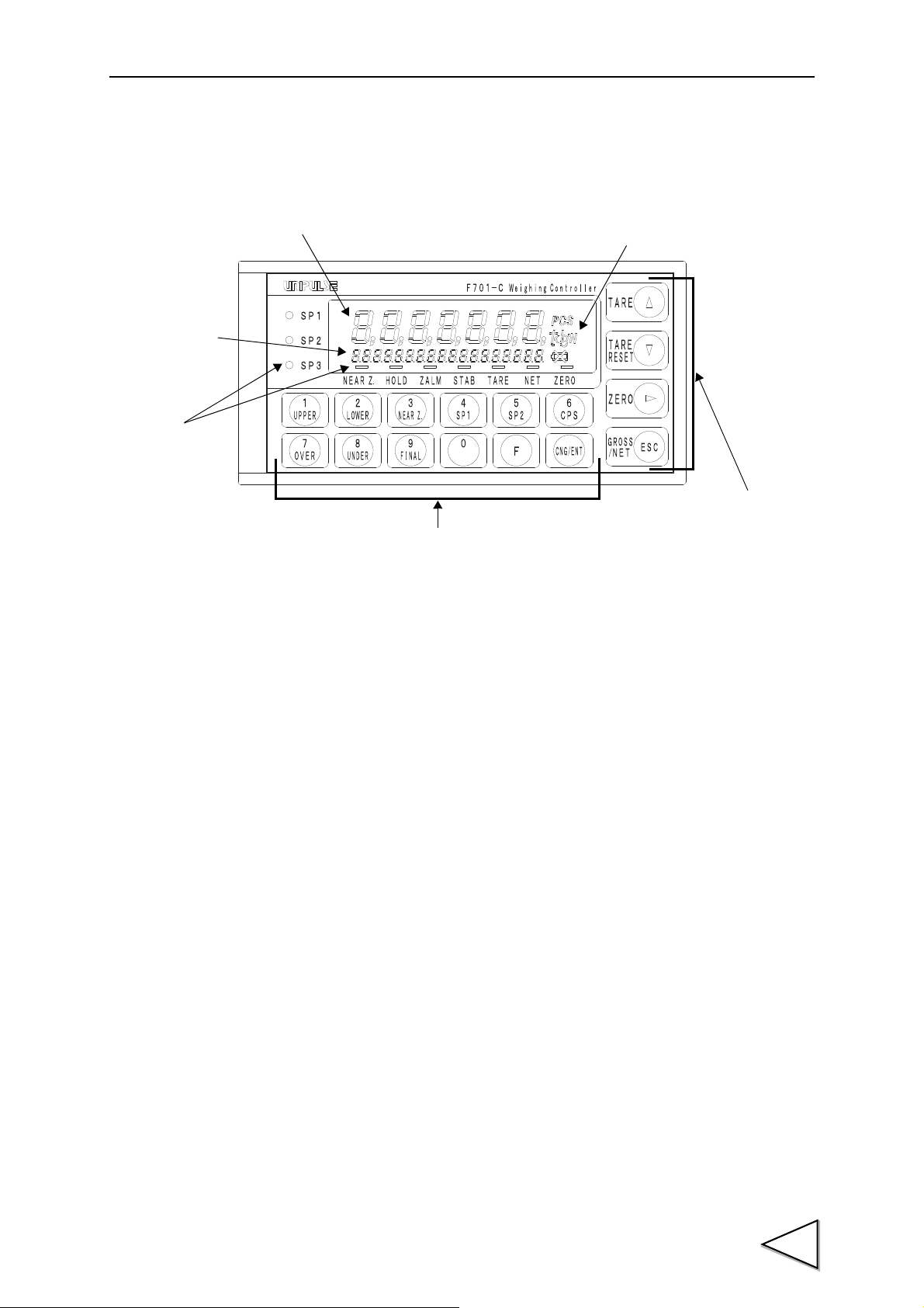
1. APPEARANCE DESCRIPTION
④ Status display
① Main display
⑤ Setting keys
③ Unit indication
⑥ Function keys
② Subdisplay
1-1. Front Panel
1.APPEARANCE DESCRIPTION
① Main display
The following three types are displayed.
(1) Weight value display
Displays the Gross weight or the Net weight.
When error occurred, the display shows error and weight value alternately.
(2) Over scale and error display
Over-scale, sequence errors and calibration errors are displayed.
* Please refer to "11.OVER SCALE & ERROR" on P.157.
(3) Setting value display
Various final discharge setting values and setting values for adjustment, such as Final and Set
Point 2, are displayed.
1
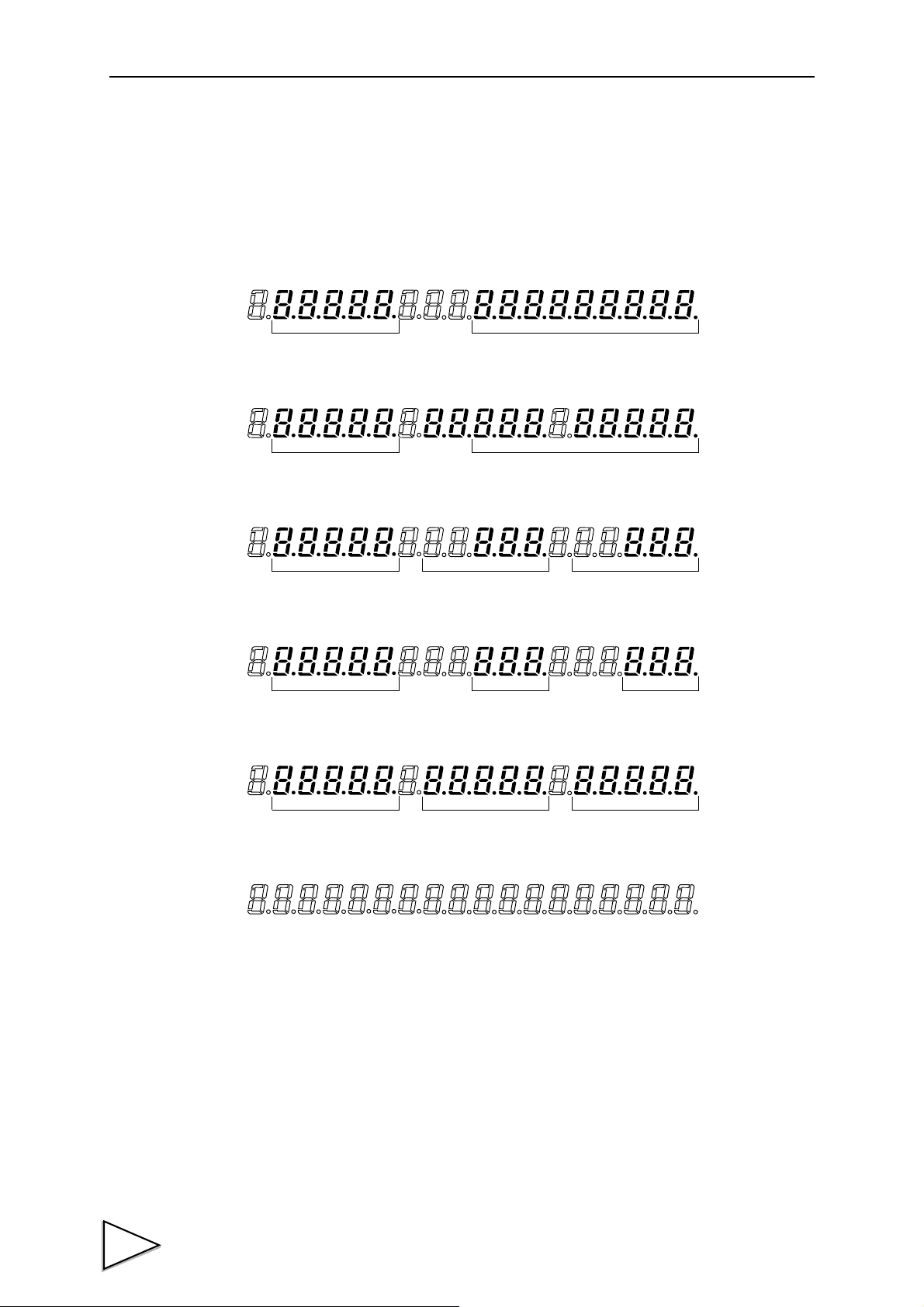
1.APPEARANCE DESCRIPTION
Accumulation Count Accumulation Value
Latest Accumulation Data Accumulation Value
Accumulation Count FinalLatest Accumulation Data
Final UnderOver
Near Zero Lower LimitUpper Limit
② Subdisplay
Weighing data, such as Accumulation Value, and various setting values are displayed by setting.
* Please refer to "- Function Selection" on P.32, "5-2.Subdisplay Selection" on P.56.
(1) Accumulation Count, Accumulation Value
(2) Latest Accumulation Data, Accumulation Value
(3) Accumulation Count, Latest Accumulation Data, Final
(4) Final, Over, Under
(5) Near Zero, Upper Limit, Lower Limit
(6) None
2

1.APPEARANCE DESCRIPTION
NEAR Z.
HOLD
“ ”
ZALM
STAB
“ ”
TARE
“ ”
NET
Accumulation Count Displays the count accumulated by the auto
accumulation command or external input/output signal,
or through RS-232C communication, etc.
Accumulation Value Displays the value accumulated by the auto
accumulation command or external input/output signal,
or through RS-232C communication, etc.
Latest Accumulation Data Displays the latest data accumulated by the auto accumulation
command or external input/output signal, or through RS-232C
communication, etc.
Final Displays the “Final” value set in the setting mode 0-9.
Over Displays the “Over” value set in the setting mode 0-7.
Under Displays the “Under” value set in the setting mode 0-8.
Near Zero Displays the “Near zero” value set in the setting mode 0-3.
Upper Limit Displays the “upper limit” value set in the setting mode 0-1.
Lower Limit Displays the “lower limit” value set in the setting mode 0-2.
③ Unit indication
The unit can select from six types: t, kg, g, N, lb and None.
④ Status display
SP1 Lights when the Set Point 1 signal is ON.
SP2 Lights when the Set Point 2 signal is ON.
SP3 Lights when the Set Point 3 signal is ON.
NEAR Z. Lights when the Near Zero signal is ON. “ ”
HOLD Lights when the weight value is held. “ ”
ZALM Lights when the DZ Regulation Value is exceeded in
Digital zero/Zero tracking operation.
(Such as when any load cell has a problem with its zero point.)
STAB Lights when the weight value is stable. “ ”
TARE Lights when Tare subtraction is performed.
Flashes when the Tare weight is displayed.
NET Lights when the weight value display is Net weight.
Goes out when it is Gross weight.
3

1.APPEARANCE DESCRIPTION
“ ”
ZERO
**
0
0
TARE
0
0
~
1
UPPER
9
FINAL
F
CNG/ENT
TARE
TARE
STAB
TARE
RESET
ZERO - Lights at a true zero point (0±1/4 scale division).
(When the 1/4 scale division display is OFF under
Function Selection in setting mode 3.)
- Lights at a true zero point (0±1/4 scale division),
and at the central point of the scale interval of the indicated
value (indicated value ±1/4 × Min. Scale Division).
(When the 1/4 scale division display is ON under
Function Selection in setting mode 3.)
Flashes when the voltage of the lithium battery for memory backup has
dropped.Replace with a new battery.
For the method of replacement, refer to "13.REPLACEMENT OF THE BACKUP
BATTERY" on P.166.
* The expression “ ” in this instruction manual shows that 「」 on the status display lights,
goes out, or flashes.
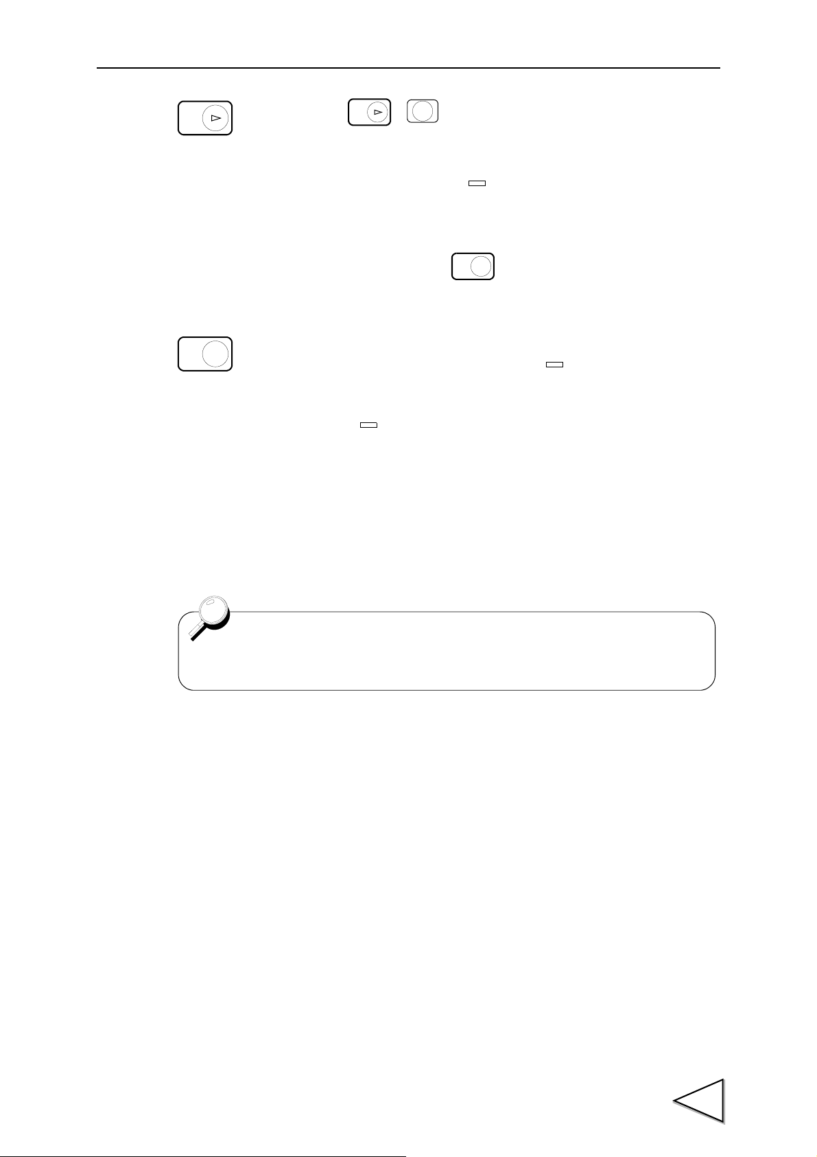
⑤ Setting keys
⑥ Function keys
When the key is pressed, the Tare weight is displayed, and
“” flashes.
(When the Tare weight display with the key is valid under
Restriction on the Tare Subtraction Function in setting mode 4.)
To go back to the weight display, press the key again.
Numerical keys to make settings.
Function key to switch the setting mode.
Change/Enter key to confirm setting items and setting values.
Key to perform one-touch Tare subtraction.
“ ” on the status display lights. (In setting mode 0)
However, Tare subtraction is performed only in the following cases
depending on the setting of Restriction on the Tare Subtraction Function
in setting mode 4.
- When the weight value is stable (when “ ” is on).
- When the range of Tare subtraction is 0 < Ta r e ≦ Capacity.
Use as an increment key for setting operation.
Key to reset Tare subtraction. (In setting mode 0)
However, the Tare Weight is not cancelled.
Use as a decrement key for setting operation.
4
1.APPEARANCE DESCRIPTION
ZERO
ZERO
CNG/ENT
ZALM
GROSS
/NET
ESC
GROSS
/NET
ESC
NET
NET
Functioning of the Function keys can be invalidated by setting of
"5-17.Invalidation of Function Keys" on P.68.
When → is pressed, Gross is zeroed
immediately. (In setting mode 0)
However, if this operation is performed with Gross out of
the DZ Regulation Value, “ ” flashes.
(For details of the DZ Regulation Value, refer to
"5-10.Zero Regulation Value" on P.62.)
To discontinue, press the key.
Use to shift setting values for setting operation.
Switch the weight display (Gross/Net). (In setting mode 0)
Pressing on Gross weight display (when “ ” is OFF)
switches to Net weight display, and pressing on Net weight display
(when “ ” is ON) switches to Gross weight display.
However, the display cannot be switched with this key if the switching
Gross weight/Net weight display is set to external input mode under
External Function Selection in setting mode 4.
Use as an ESC key for setting operation.
5
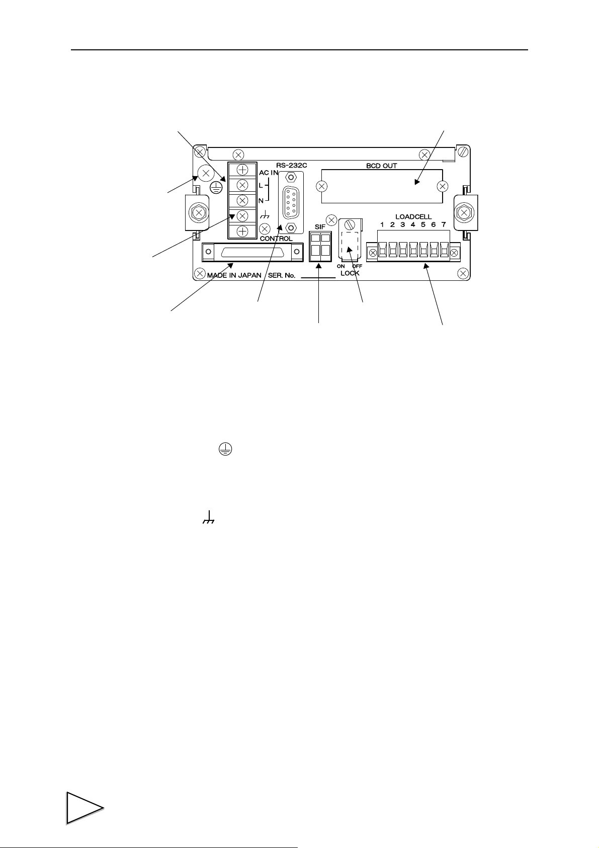
1.APPEARANCE DESCRIPTION
① AC power input terminal block
④ Control connector
⑥ SI/F terminal block
⑦ LOCK switch
⑧ Load cell input terminal block
⑨ Option space
③ Frame ground
⑤ RS-232C connector
② Protective ground
1-2. Rear Panel
① AC power input terminal block
Connect AC power code. The input voltage is 100V ~ 240V AC.
The frequency is 50/60Hz.
② Protective ground
Be sure to ground the protective ground terminal to prevent electric shocks.
③ Frame ground
Please ground the frame ground terminal to prevent failures due to static electricity.
(The frame and the frame ground terminal are conducted.)
It may be better to remove depending on the environment of the installation location.
④ Control connector
This is a connector to input external signals and output control signals. The Input/Output circuit and
6
internal circuit are photocoupler-insulated electrically.
The applicable connector is the following (accessory) manufactured by Fujitsu Component or an
equivalent:
Connector : FCN-361J024-AU
Cover : FCN-360C024-B

1.APPEARANCE DESCRIPTION
⑤ RS-232C connector
RS-232C connector for receiving and transmitting weight data and status information.
The applicable connector is JAE DE-09SN or its equivalent.
⑥ SI/F terminal block
2-wire serial interface is to connect unipulse peripheral equipment such as printer, remote display
or data converter.
⑦ LOCK switch
LOCK switch for avoiding changes of setting value, it prohibits to change setting value while the
switch is ON.
⑧ Load cell input terminal block
This is a terminal block to connect load cell(s).
The applicable terminal block is Osada-manufactured ETB42-07P.
⑨ Option space
One of the following options can be mounted.
- BCD parallel data output interface (BCO)
- D/A converter (DAC)
- RS-485 communication interface (485)
- CC-Link interface (CCL)
7

2.CONNECTION
Load cell terminal block
2. CONNECTION
2-1. Load cell Connection
The voltage application of F701-C is 10V, and the maximum current is 120mA, to which up to four
350Ω load cells can be connected in parallel.
Load cell terminal block pin assignments
Pin No. Signal (6-wire) Signal (4-wire)
1+SIG +SIG
2-SIG -SIG
3+EXC +EXC
4+S
5 -EXC -EXC
6-S
7 SHIELD SHIELD
(Connect 3 to 4)
(Connect 5 to 6)
8
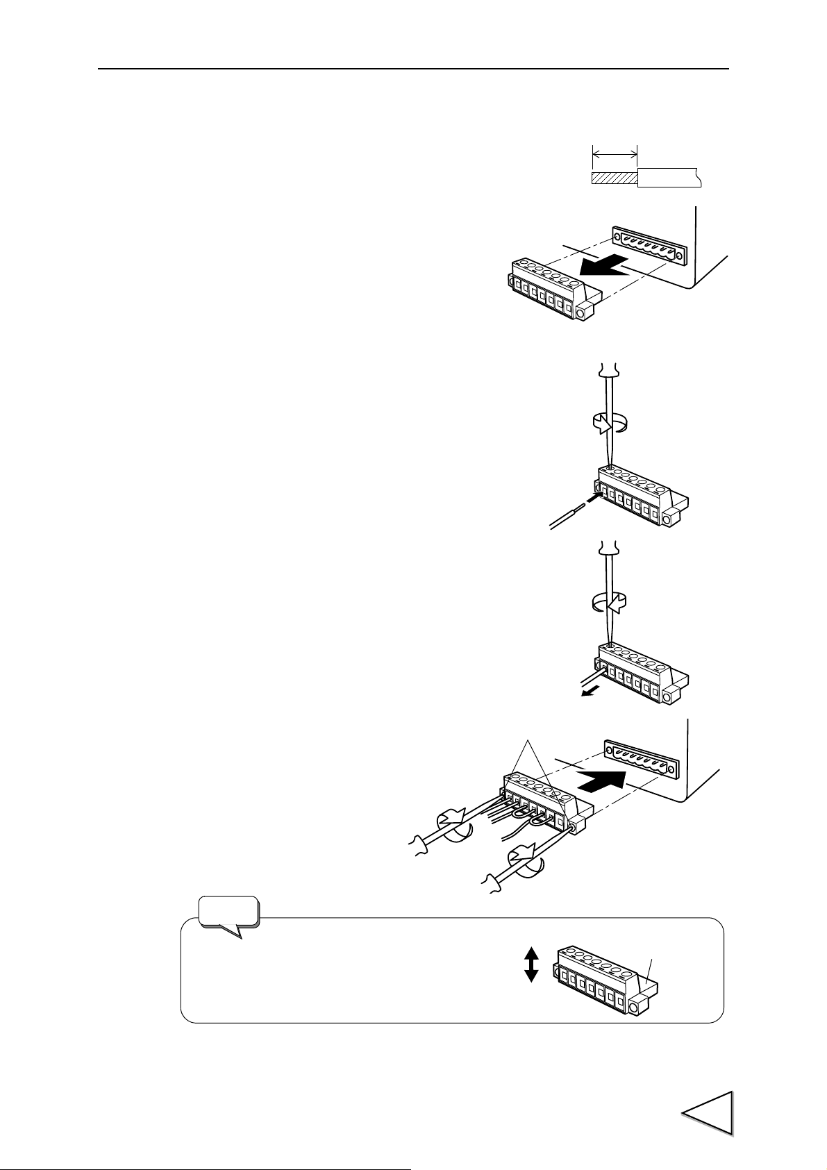
Method of connection
5mm
Hole
Turn
counterclockwise.
Turn
clockwise.
Turn clockwise.
Screws(two)
When mounting the terminal block to the
F701-C body, check its vertical orientation.
(See the illustration on the right-hand side.)
UP
DOWN
Request
Insertion side
1) Peel the sheath of the wire to be connected 5mm.
2) Twist the end to such an extent that it will not become loose.
3) Remove the terminal block from the F701-C body
with a strong pull.
4) Loosen the screw with a screwdriver to open the hole.
A Phillips screwdriver with a shaft diameter of 3 ~ 3.5mm
#1 is recommendable
(precision screwdriver, etc.).
5) Insert the wire into the hole so as not to loosen the end.
2.CONNECTION
6) Tighten the screw with the screwdriver.
7) Lightly pull the wire to check that it is clamped securely.
* Connectable wires are 0.21 ~ 3.31mm
2
(AWG12 ~ 24).
Recommendable tightening torque is 0.5Nm.
8) Insert the wire-connected plug into
the F701-C body, and tighten the
screws (two).
9
2.CONNECTION
+IN
-OUT
-IN
+EXC
+S
-S
-EXC
+SIG
-SIG
SHIELD
+OUT
3
4
6
5
1
2
7
Load cell
+IN
-OUT
-IN
+EXC
+S
-S
-EXC
+SIG
-SIG
SHIELD
+OUT
3
4
6
5
1
2
7
Load cell
These jumpers MUST be connected.
- The load cell excitation voltage of the F701-C is 10V. Heating or breakage may occur
unless the load cells maximum excitation voltage is 10V or more.
- When using the F701-C with the four-wire load cell connected, be sure to connect +EXC
and +S, and -EXC and -S. Even if +S and -S are not connected, normal operation is
performed apparently, but heating or breakage may occur because excessive voltage is
applied to the load cell.
CAUTION
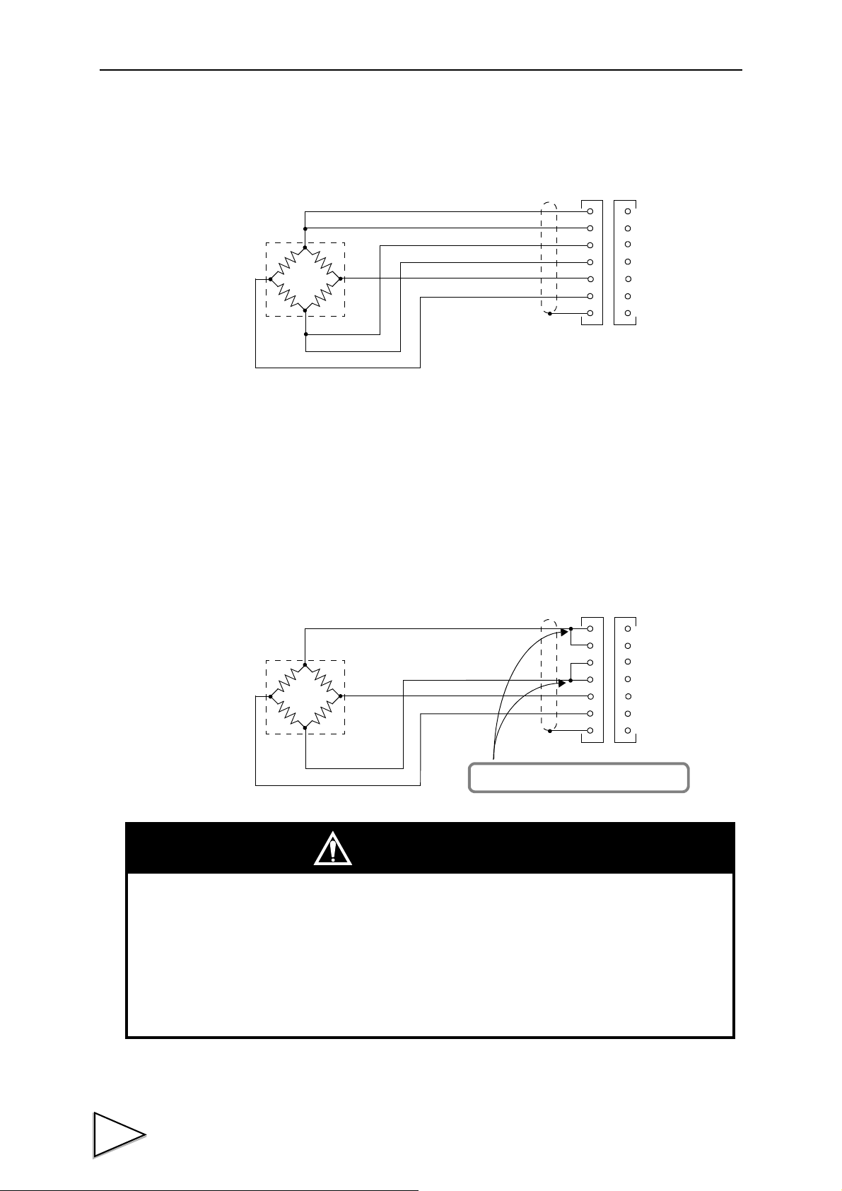
2-1-1. 6-wire Connection
The load cell input of the F701-C is a 6-wire (remote sense) connection. 6-wire shielded load cell
cable should be used and kept separate from AC or other noise generating wire.
* Remote sense lines are used to detect and correct variations in excitation voltage over long cable
runs.
2-1-2. 4-wire Connection
Connect 3 and 4, and 5 and 6 as shown below.
Even 4 and 6 on the terminal block are open, normal operation is performed apparently, but heating
or breakage may occur because excessive voltage is applied to the load cell.
For connection, use the accessory jumper lines.
10

2.CONNECTION
R
R
R
R
R
R
+EXC
-SIG
+SIG
-EXC
+EXC
-SIG
-EXC
+SIG
SHIELD
+S
-S
When connecting several load cells in parallel, load cell capacity should be higher than
expected load to compensate for mechanical shock or eccentric loading.
R
R
The group of “n” parallel load cells
viewed from this device side can be
regarded as a unit load cell the rated
capacity of which is multiplied by “n”
and the sensitivity of which is
unchanged. The averaging resistance (R)
should be 300 to 500Ω, equal in relative
ratio and excellent in temperature
coefficient. No averaging resistance is
needed if load cells with consideration
for parallel connection are used.
Request
2-1-3. Connecting Load cells in Parallel
In some industrial weighing apparatus, two or more load cells may be connected in parallel to form
a hopper scale or track scale. The manner of connection is shown below.
Parallel connection can simply be made by using the optionally available B410 (summing box for
4-point multi load cell).
2-1-4. Sensor Cable
Cable colors of sensors may differ from one manufacturer to another (it may even differ from one
model to another for some products). Refer to the sensor manual (or data sheet) and check signal
names and colors in order to connect the cables correctly.
11
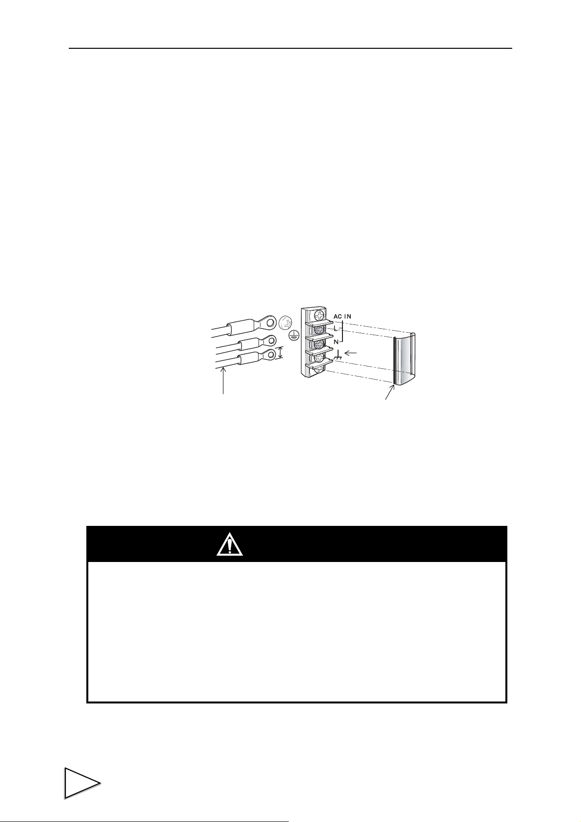
2.CONNECTION
block cover
Within 6mm
AC power cord
Frame
ground
- Connect with no power applied because it may cause an electric shock.
- The attached AC cable is designed for domestic use in Japan, and its rating is 125V AC,
7A. For use at voltages exceeding the rating and for overseas use, have a separate AC
cable prepared.
- Since the F701-C has no power switch, install a breaker.
- Be sure to ground the protective ground terminal to prevent electric shocks.
Do not use other screws than that attached to the main body.
CAUTION
2-2. Connection of the Power Input Terminals
Connect AC power cord. The input voltage is 100V ~ 240V AC.
The frequency is 50/60Hz.
1) Make sure that no power is applied.
2) Remove the terminal block cover.
3) Remove the two screws(M3) of the terminal block, align the crimp contacts with the
screw holes, and then tighten the screws.
4) Mount the terminal block cover.
5) Remove the screws(M4) of the protective ground, align the crimp contacts with the
screw holes, and then tighten the screws.
2-3. Connection of the Guard Ground
The grounding terminal is for prevention of electric shocks.
2
Use an approx. 0.75mm
thick wire, and be sure to ground.
12
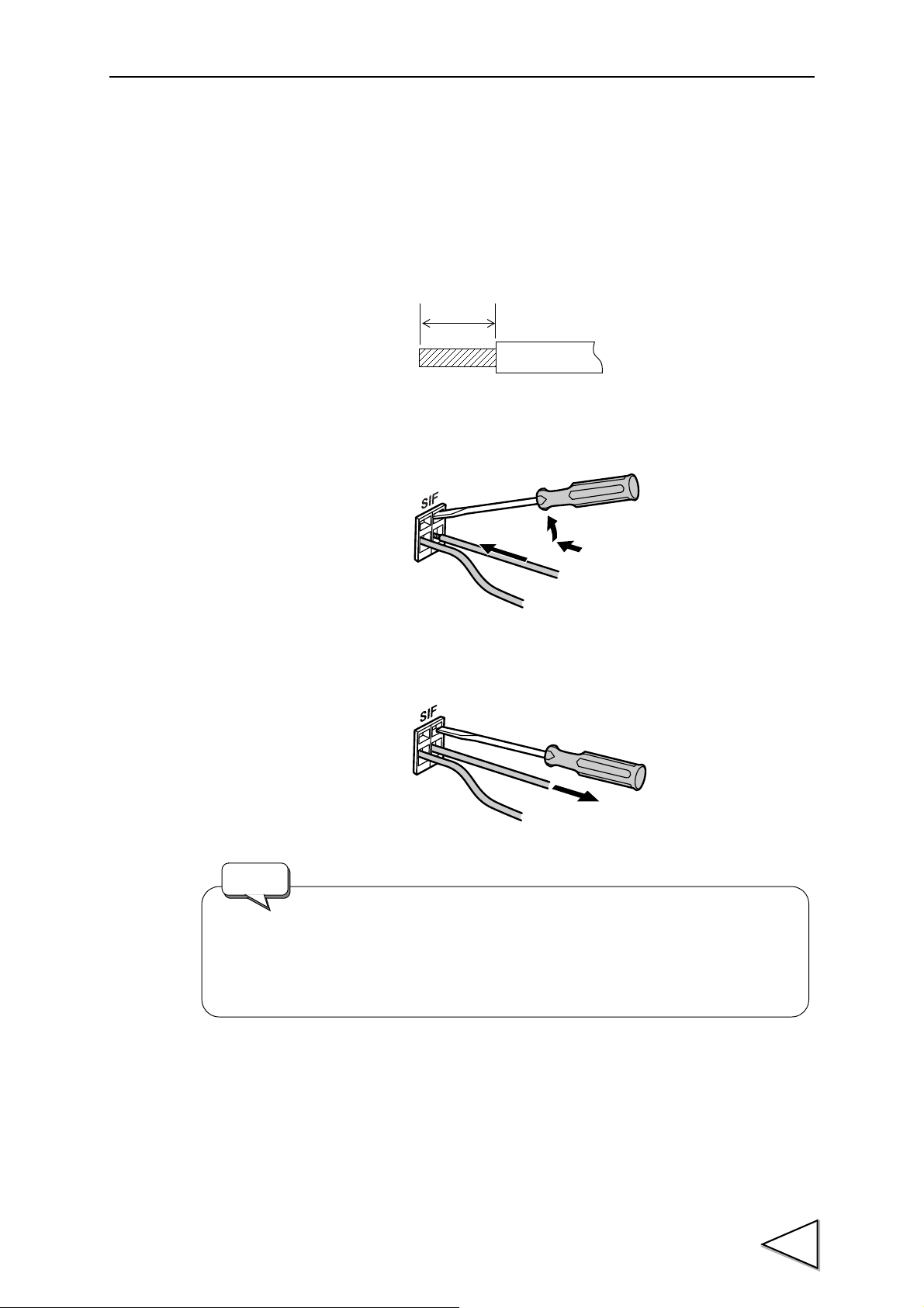
2-4. SI/F Connection
5 to 6mm
- Cable can be from 24 ~ 14AWG (0.2 ~ 2.5mm2).
- It is not necessary to solder the cable wires or to fix a solderless terminal.
- If several cables to be inserted to the same hole, twist those cable wires
together and insert.
Request
The SI/F allows connection of up to three nonpolarized external devices.
As for wire materials, use parallel 2-core cables, cabtyre cables, or the like.
Connect to the cage clamp type terminal block by using the attached mini screwdriver.
1) Strip the casing 0.2in (6mm) on the cable to be connected.
Twist the bare wire to fit the terminal hole.
2) Insert the supplied screwdriver into the upper hole and lift upward.
3) Insert the twisted wires into the lower hole.
2.CONNECTION
4) Pull the screwdriver out from the upper hole.
5) Make sure cable is clamped securely and does not come out with a slight tug.
13

2.CONNECTION
2-5. Connection of the Control Connector
Connect to the control connector (rear panel “CONTROL”).
The applicable connector is the following (accessory) manufactured by Fujitsu Component or an
equivalent:
Connector : FCN-361J024-AU
Cover : FCN-360C024-B
2-5-1. Control Connector-Pin Assignment
For details, please refer to "9.EXTERNAL INPUT/OUTPUT SIGNALS (CONTROL
CONNECTOR)" on P.111.
A1
A2 In G/N B2 In Input Selection 1 *1
A3 In D/Z ON B3 In Input Selection 2 *1
A4 In Tare Subtraction ON B4 In Input Selection 3 *1
A5 In Tare Subtraction OFF B5 In Input Selection 4 *1
A6 Out Near Zero B6 Out Lower Limit
A7 Out SP1 B7 Out Upper Limit
A8 Out SP2 B8 Out Stable
A9 Out SP3 B9 Out Output Selection 1 *2
A10 Out Under B10 Out Output Selection 2 *2
A11 Out Over B11 Out Output Selection 3 *2
A12
* * : The COM (common) terminals are connected inside.
* *1 : Selectable by setting.
* *2 : Selectable by setting. (For details, please refer to "6-11.Weight Error / Sequence Error" on
COM B1
*
COM B12
*
(For details, please refer to "9-4-11.Input Selection" on P.117)
P.101, "6-8.Complete Signal Output Mode / Complete Output Time / Judging Time /
Comparison Inhibit Time / Output Selection 2" on P.93, "9-5-7.Accumulation Error" on
P. 11 9 )
*
*
COM
COM
14
* SP1 turns ON when Weight value ≧ Final - SP1
SP2 turns ON when Weight value ≧ Final - SP2
SP3 turns ON when Weight value ≧ Final - CPS

2-5-2. How to Assemble the Connector
Connector
Pan-head machine screw
M2×8 (short) (two)
Nut M2 (four)
Pan-head machine screw
M2×10 (long) (two)
Washer (two)
Case (two)
Screw (two)
(1) Set the connector and screws (two) into the grooves of the case (one side).
2.CONNECTION
(2) Cover with the other case, and fit the cases.
(3) Tighten the M2×8 pan-head machine screws (two).
Tighten the M2×10 pan-head machine screws (two).
Be aware that washers should be set to the M2×10 pan-head machine screws (two).
15

2.CONNECTION
Vcc
F701-C
Inside
Approx.
COM
Transistor
+12V
Push
Toggle switch Relay
IN
IN
Open OFF
Short ON
- Do not apply external voltage to the signal input circuit.
- The external element is required to withstand Ic=10mA.
- Leakage from the external element is required to be 100μA or below.
switch
IC=6mA
TTL open collector
(ON when IN is HI)
Spark killer
Load
Spark killer
DC Power
Va ri s t o r
Load
AC power
Relay
Ve xt
Output data
Tr
0
OFF
1
ON
F701-C
Inside
Vcc
+12V
COM
Vceo=30V(max)
Ic =120mA (max)
- Use external power source (up to DC30V) for driving relay
(Vext).
- Do not short-circuit the load, such as a coil of relay, that will
break the output transistor.
- Connect a surge absorber or a speark killer to the relay
circuit as shown in the draft so that to reduce noise trouble
and extend the life of relay.
Noise trouble can be reduced, and the relay’s life can be
extended.
- Transistor status
2-5-3. Equivalent Circuit (Input)
A signal is inputted to the signal input circuit by short-circuiting or opening the input terminal and
the COM terminal. Short-circuiting is effected by means of a contact (such as a relay or a switch) or
a noncontact (such as a transistor or an open-collector TTL).
2-5-4. Equivalent Circuit (Output)
The signal output circuit is open-collecter output of a transistor.
16
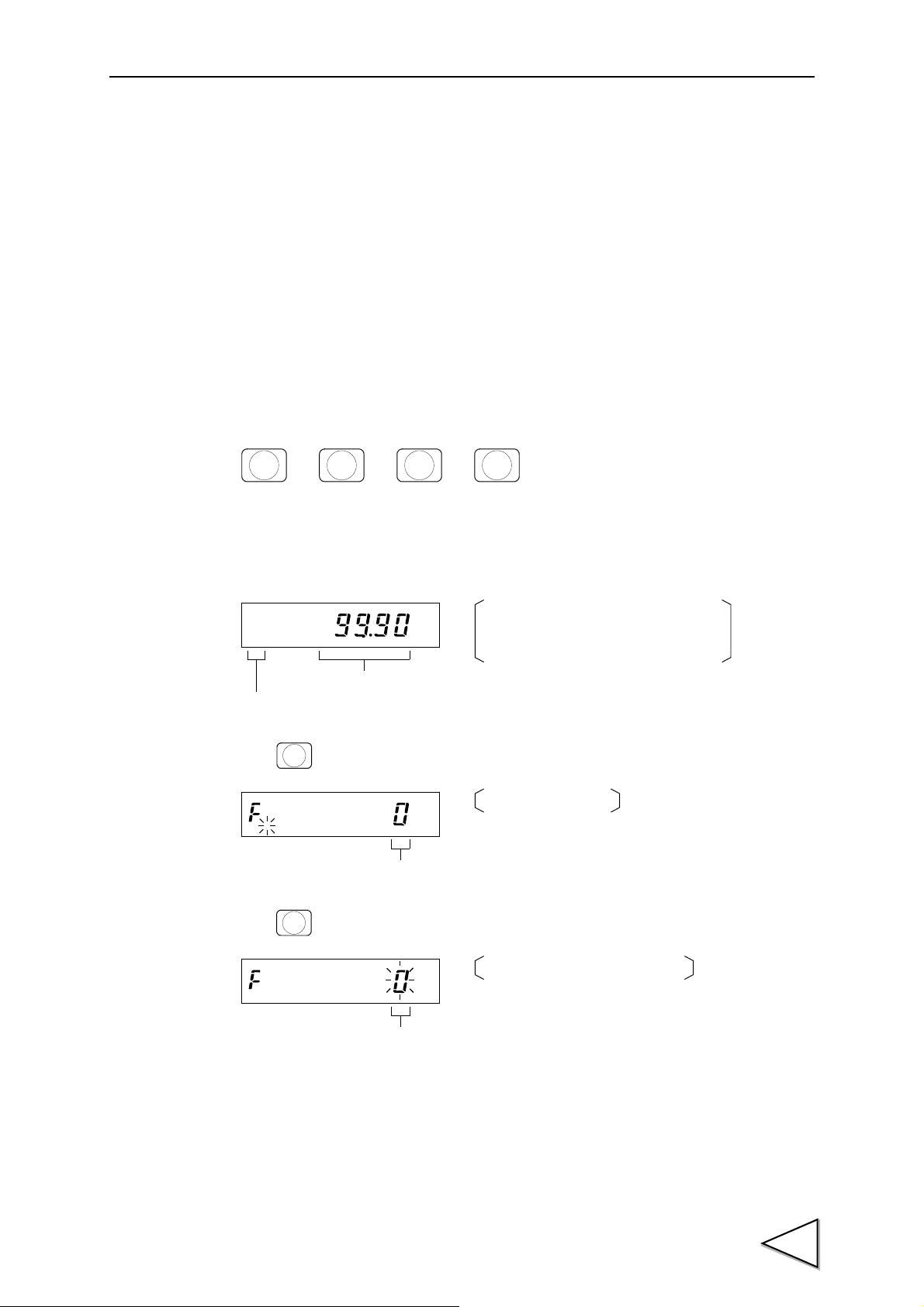
3. METHODS OF SETTING
→→→
F
CNG/ENT CNG/ENT
3
NEAR Z
.
kg
Normally the state is in setting mode 0.
The mode number is not displayed for
mode 0.
Setting mode number
Present weight value
F
kg
,
Setting mode number
The display changes.
,
CNG/ENT
kg
,
Setting mode number
The setting mode number blinks.
,
3-1. Setting Procedure
Change settings in the order of “setting mode selection” → “setting item selection” → “setting
value entry”.
3-1-1. Method of Selecting a Setting Mode
In the text, the method of selecting a setting mode is described as follows:
(Example) For selecting setting mode 3
3.METHODS OF SETTING
This operation can be performed by the following procedure.
1) Press the key when the weight value is displayed.
2) Press the key.
17

3.METHODS OF SETTING
3
NEAR Z
.
kg
,
Setting mode number
The input number blinks.
,
CNG/ENT
Present weight value
The selected setting mode number
Setting mode number
and weight value are displayed
(Setting mode display).
kg
By pressing the key when the setting mode number is displayed, you
can go back to normal display (Setting mode 0).
GROSS
/NET
ESC
3) Select the setting mode number. ( )
4) Press the key.
18

3.METHODS OF SETTING
→→ →
1
UPPER
CNG/ENT CNG/ENT
1
UPPER
kg
,
Present setting value
The setting mode number, setting
Setting mode number
item number, and present setting
Setting item number
value are displayed.
,
CNG/ENT
kg
,
Present setting value
The highest digit of the setting
Setting mode number
value blinks.
Setting item number
,
0
5
SP2
000
kg
,
Setting value
Every time a number is pressed,
Setting mode number
the blinking digit moves to the lower one.
Setting item number
Since the highest digit starts blinking again
after a number is input to the lowest digit,
setting can be redone again and again.
,
CNG/ENT
Present weight value
The display returns to the setting
Setting mode number
mode display.
kg
3-1-2. Method of Entering a Setting Value
In the text, the method of entering a setting value is described as follows:
(Example 1) For setting the Balance Weight Value to 50.00kg
(Setting by numerical input: Unsigned)
This operation can be performed by the following procedure.
* However, it is assumed that setting mode 3 has already been selected.
1) Select the setting item.
(Since the setting item number of the Balance Weight Value is 1, press the key.)
2) Press the key.
3) Input the setting value. ( )
4) After the correct setting value is input, press the key to enter the setting value.
19

3.METHODS OF SETTING
→→ →
6
CPS
CNG/ENT CNG/ENT
6
CPS
Present setting value
The setting mode number, setting
Setting mode number
item number, and present setting
Setting item number
value are displayed.
kg
,
CNG/ENT
Present setting value
The highest digit of the setting
Setting mode number
value blinks.
Setting item number
kg
,
003
NEAR Z
.
0
F
Setting value
Every time a number is pressed, the blinking
Setting mode number
digit moves to the lower one.
Setting item number
Since the highest digit starts blinking again
after a number is input to the lowest digit,
setting can be redone again and again.
kg
,
F
Press the key becomes negative setting
value and display the minus sign.
F
Press the key, when minus sign displayed,
becomes positive setting value and will not
display the minus sign.
CNG/ENT
Present weight value
The display returns to the setting
mode display.
kg
(Example 2) For setting the Compensation to -0.30kg
This operation can be performed by the following procedure.
* However, it is assumed that setting mode 0 has already been selected.
1) Select the setting item.
(Since the setting item number of the Compensation is 6, press the key.)
(Setting by numerical input: Signed)
2) Press the key.
3) Input the setting value. ( → )
4) After the correct setting value is input, press the key to enter the setting value.
20

3.METHODS OF SETTING
→→ →
7
OVER
CNG/ENT CNG/ENT
ZERO ZEROZERO
7
OVER
Present setting value
Setting mode number
Setting item number
The setting mode number, setting
item number, and present setting
value are displayed.
kg
,
CNG/ENT
Present setting value
Setting mode number
Setting item number
The highest digit of the setting
value blinks.
kg
,
ZERO
ZERO
ZERO
ZERO
kg
,
Not defined
Setting mode number
Setting item number
1/4 scale division display
Decimal place
Display frequency
ZERO
Subdisplay selection
Every time the key is pressed,
the blinking digit moves to the lower one.
(Example 3) For setting the 1/4 scale division display to OFF (Setting from choices)
This operation can be performed by the following procedure.
* However, it is assumed that setting mode 3 has already been selected.
1) Select the setting item.
(Since the setting item number of the 1/4 scale division display is 7, press the key.)
2) Press the key.
3) Move with the key until the digit you want to set blinks. ( )
21

3.METHODS OF SETTING
0
1/4 scale division display
The blinking digit moves to the lower one.
Setting mode number
Setting item number
Since the blinking digit moves every time
the key is pressed, setting can be
redone again and again.
ZERO
kg
,
CNG/ENT
kg
Present weight value
Setting mode number
The display returns to the setting
mode display.
By pressing the key when the setting item number is displayed (while
changing a setting value after selecting an item), you can exit the item.
(The display returns to the setting mode display.)
GROSS
/NET
ESC
4) Select from choices.
(Since the 1/4 scale division display should be turned off, press .)
5) After the correct choice is input, press the key to enter the choice.
22

3.METHODS OF SETTING
Setting mode 0 Setting mode 1 Setting mode 2 Setting mode 3
Upper Limit
/ P.24
Comparison Inhibit Time
/ P.26
Weighing Function 1
/ P.28
Balance Weight Value
/ P.31
Lower Limit
/ P.24
Judging Time
/ P.26
Weighing Function 2
/ P.28
Capacity
/ P.31
Near Zero
/ P.24
Complete Output Time
/ P.26
Weighing Function 3
/ P.29
Min. Scale Division
/ P.31
Set Point 1
/ P.24
Adjust Feeding Time
/ P.26
Sequence Mode
/ P.29
Net Over
/ P.31
Set Point 2
/ P.24
Auto Zero Times
/ P.26
Function Key Invalid
/ P.30
Gross Over
/ P.31
Compensation
/ P.24
Judging Times
/ P.26
Digital Filter
/ P.30
DZ Regulation Value
/ P.31
Over
/ P.25
Auto Free Fall
Compensation Regulation
/ P.27
Motion Detection
/ P.30
Function Selection
/ P.32
Under
/ P.25
Analog Filter
/ P.27
Zero Tracking Period
/ P.30
Gravitational Acceleration
(area number)
/ P.32
Final
/ P.25
Tare Weight
/ P.27
Zero Tracking Range
/ P.30
Gravitational Acceleration
(acceleration)
/ P.32
1
UPPER2LOWER
3
NEAR Z
.
4
SP1
5
SP2
6
CPS7OVER
8
UNDER
9
FINAL
ZERO
* When each setting mode is selected, the 1 ~ 9 keys function as setting item selection keys.
Setting mode 4 Setting mode 5 Setting mode 8 Setting mode 9
D/A Output Mode
/ P.33
Input Selection
/ P.36
Average Weight
/ P.38
Span Calibration
/ P.53
D/A Zero Output Weight
/ P.33
Output Selection
/ P.36
Max. Value
/ P.38
Equivalent Calibration
/ P.54
D/A Full Scale
/ P.33
CC-Link I/F
Number of occupied station &
Transmission speed
(Refer to separate-volume spec.
)
Min. Value
/ P.38
RS-485 I/F
/ P.33
CC-Link I/F
Station No.
(Refer to separate-volume spec.
)
General Standard Deviation
/ P.38
ID Number
/ P.34
Sample Standard Deviation
/ P.38
RS-232C I/F
/ P.34
Accumulation Count (n)
/ P.38
External Function Selection
/ P.35
Latest Accumulation Data
/ P.38
Setting Value LOCK
/ P.35
Max. - Min. (R)
/ P.39
Restriction on the Tare
Subtraction Function
/ P.35
Option Board
/ P.39
Pass Word
/ P.109
Zero Calibration
/ P.51
1
UPPER
2
LOWER
3
NEAR Z
.
4
SP1
5
SP26CPS7OVER
8
UNDER
9
FINAL
ZERO
3-2. Setting Mode
23

3.METHODS OF SETTING
(0 ~ 99999)
1
UPPER
(0 ~ 99999)
2
LOWER
(0 ~ 99999)
3
NEAR Z
.
(0 ~ 99999)
4
SP1
(0 ~ 99999)
5
SP2
(-9999 ~ 9999)
* If negative setting value, display the sign.
6
CPS
3-2-1. Setting Mode 0
In setting mode 0, setting values for final discharging control are to be set.
- Upper Limit
(For details, please refer to "6-6" on P.90.)
- Lower Limit
(For details, please refer to "6-6" on P.90.)
- Near Zero
(For details, please refer to "6-6" on P.90.)
- Set Point 1
(For details, please refer to "6-4" on P.86.)
- Set Point 2
(For details, please refer to "6-4" on P.86.)
24
- Compensation
(For details, please refer to "6-4" on P.86.)
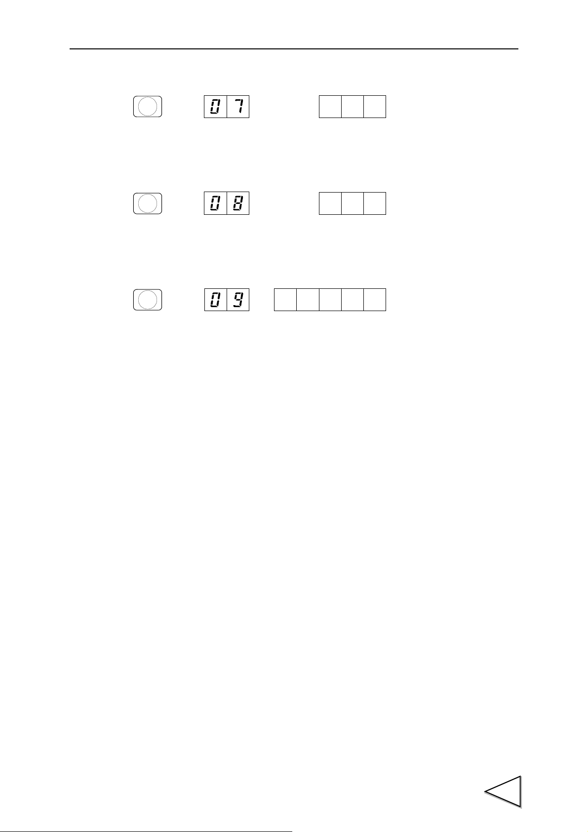
- Over
(0 ~ 999)
7
OVER
(0 ~ 999)
8
UNDER
(0 ~ 99999)
9
FINAL
(For details, please refer to "6-4" on P.86.)
- Under
(For details, please refer to "6-4" on P.86.)
- Final
3.METHODS OF SETTING
(For details, please refer to "6-4" on P.86.)
25
3.METHODS OF SETTING
.
sec. (0.00 ~ 9.99)
1
UPPER
.
sec. (0.00 ~ 9.99)
2
LOWER
.
sec. (0.00 ~ 9.99)
3
NEAR Z
.
.
sec. (0.00 ~ 9.99)
4
SP1
(0 ~ 99)
5
SP2
(0 ~ 99)
6
CPS
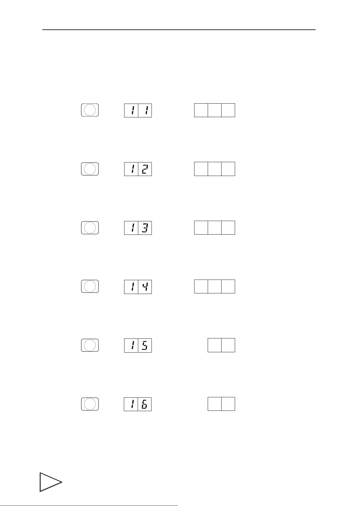
3-2-2. Setting Mode 1
In setting mode 1, output signals for final discharging control and parameters in sequence mode,
etc., are to be set.
- Comparison Inhibit Time
(For details, please refer to "6-8" on P.93.)
- Judging Time
(For details, please refer to "6-8" on P.93.)
- Complete Output Time
(For details, please refer to "6-8" on P.93.)
- Adjust Feeding Time (Effective when selecting sequence mode)
(For details, please refer to "6-9" on P.96.)
- Auto Zero Times (Effective when selecting sequence mode)
(For details, please refer to "6-9" on P.96.)
26
- Judging Times (Effective when selecting sequence mode)
(For details, please refer to "6-9" on P.96.)

- Auto Free Fall Compensation Regulation
(0 ~ 99999)
7
OVER
(0 ~ 3)
8
UNDER
(0 ~ 99999)
9
FINAL
(For details, please refer to "6-3" on P.83.)
- Analog Filter
(For details, please refer to "5-4" on P.57.)
- Tare Weight
3.METHODS OF SETTING
(For details, please refer to "5-13" on P.65.)
27

3.METHODS OF SETTING
Discharging control mode
2 : External selection
1 : Discharging control
0 : Feeding control
Near Zero comparison
4 : ON when |Net weight| ≦ Near Zero
setting value
3 : ON when |Gross weight| ≦ Near Zero
setting value
2 : Comparison OFF
1 : ON when Net weight ≦ Near Zero
setting value
0 : ON when Gross weight ≦ Near Zero
setting value
Final and Over/Under comparison
2 : Comparison OFF
1 : Net weight
0 : Gross weight
Upper/Lower limit comparison
2 : Comparison OFF
1 : Net weight
0 : Gross weight
(For details, please refer to
"6-1-3" on P.75.)
(For details, please refer to
"6-7" on P.91.)
(For details, please refer to "6-7" on P.91.)
(For details, please refer to "6-7" on P.91.)
1
UPPER
* Not defined Complete signal output mode
2 : ON for the complete output time from
when the judging timer has expired
or from when the weight value
becomes stable after the SP3 signal
turns ON.
1 : ON for the complete output time from
when the weight value becomes
stable after the judging timer has
expired.
0 : ON for the complete output time from
when the judging timer has expired.
Over/Under comparison mode
3 : Comparison is made, and the
weight value is held when the
complete output is ON.
2 : Comparison is made when the
complete output is ON.
1 : Comparison is made when the
external judgment input is ON.
0 : Comparison regularly
Upper/Lower limit comparison mode
1 : Comparison is made when the
external judgment input is ON.
0 : Comparison regularly
Accumulation command selection
1 : Auto accumulation
command ON
0 : Auto accumulation
command OFF
(For details, please refer to "6-7" on P.91.)
(For details, please refer to "6-7" on P.91.)
(For details, please refer to "6-8" on P.93.)
(For details, please refer to
"7-4" on P.107.)
2
LOWER
3-2-3. Setting Mode 2
In setting mode 2, the display and internal functions of the F701-C are to be tuned.
- Weighing Function 1
- Weighing Function 2
28

- Weighing Function 3
3 : AFFC. coefficient 1/4
2 : 〃 2/4
1 : 〃 3/4
0 : 〃 1
1 : Digital tare subtraction
ON
0 : Digital tare subtraction
OFF
2 : AFFC. ON
(Communication OP invalid)
1 : 〃 ON
0 : 〃 OFF
Average count of AFFC.
(1 ~ 9)
(For details, please refer to
"6-3" on P.83.)
(For details, please refer to
"5-13" on P.65.)
(For details, please refer to
"6-3" on P.83.)
(For details, please refer to
"6-3" on P.83.)
3
NEAR Z
.
1 : Negative Compensation
Effect
0 : Negative Compensation
Inhibit
(For details, please refer to
"6-5" on P.89.)
1 : Sequence mode
0 : Simple comparison mode
(Sequence control)
1 : At start-time, weight
value check ON
0 : 〃 OFF
1 : Adjust feeding ON
0 : 〃 OFF
(Sequence control)
1 : At start-time,
Near Zero check ON
0 : 〃 OFF
(For details, please refer to
"6-9" on P.96.)
(For details, please refer to
"6-2-3" on P.82.)
(For details, please refer to
"6-9" on P.96.)
(For details, please refer to
"6-9" on P.96.)
4
SP1
3.METHODS OF SETTING
- Sequence Mode
29
3.METHODS OF SETTING
[TARE] key
1 : Valid
0 : Invalid
[GROSS / NET] key
1 : Valid
0 : Invalid
[TARE RESET] key
1 : Valid
0 : Invalid
[ZERO] key
1 : Valid
0 : Invalid
5
SP2
Digital Filter
(0 ~ 256)
6
CPS
Period (sec.) Range
* Set the stability detection parameter.
(0.0 ~ 9.9) (0 ~ 99)
-
.
7
OVER
Period (sec.)
(0.0 ~ 9.9)
.
8
UNDER
Range
(0 ~ 9999)
9
FINAL
- Function Key Invalid
(For details, please refer to "5-17" on P.68.)
- Digital Filter
(For details, please refer to "5-3" on P.56.)
- Motion Detection
(For details, please refer to "5-6" on P.58.)
- Zero Tracking Period
(For details, please refer to "5-7" on P.60.)
30
- Zero Tracking Range
(For details, please refer to "5-7" on P.60.)

3-2-4. Setting Mode 3
(0 ~ 99999)
1
UPPER
(0 ~ 99999)
2
LOWER
(1 ~ 100)
3
NEAR Z
.
(0 ~ 99999)
4
SP1
(0 ~ 99999)
5
SP2
(0 ~ 9999)
6
CPS
In setting mode 3, setting values relating to initial calibration are to be set.
- Balance Weight Value
(For details, please refer to "4-4-6" on P.48.)
- Capacity
(For details, please refer to "4-4-4" on P.47.)
3.METHODS OF SETTING
- Min. Scale Division
(For details, please refer to "4-4-5" on P.47.)
- Net Over
(For details, please refer to "6-10" on P.100.)
- Gross Over
(For details, please refer to "6-10" on P.100.)
- DZ Regulation Value
(For details, please refer to "5-10" on P.62.)
31

3.METHODS OF SETTING
Display frequency
3 : 25 times/sec.
2 : 13 times/sec.
1 : 6 times/sec.
0 : 3 times/sec.
Decimal place
1/4 scale division display
1 : ON
0 : OFF
(For details, please refer to
"5-1" on P.55.)
(For details, please refer to
"4-4-3" on P.46.)
(For details, please refer to
"4-4-8" on P.50.)
7
OVER
Subdisplay selection
5 : Near Zero /
Upper Limit /
Lower Limit
4 : Final / Over / Under
3 : Accumulation Count /
Latest Accumulation Data /
Final
2 : Latest Accumulation Data /
Accumulation Value
1 : Accumulation Count /
Accumulation Value
0 : None
(For details, please refer to
"5-2" on P.56.)
Unit
5 : N 4 : lb
3 : kg 2 : g
1 : t 0 : None
(For details, please refer to
"4-4-2" on P.46.)
3 :
2 :
1 :
0 :
When using the F701-C for any balance weight to undergo type approval by the
Measurement Law, set the 1/4 scale division display to OFF. If it is set to OFF,
the “zero point” lights only at a true zero point (0±1/4 scale division).
Request
(0 ~ 16)
8
UNDER
(9.700 ~ 9.999)
.
9
FINAL
- Function Selection
- Gravitational Acceleration (Area number input)
(For details, please refer to "4-4-7" on P.48.)
- Gravitational Acceleration (Acceleration input)
(For details, please refer to "4-4-7" on P.48.)
32
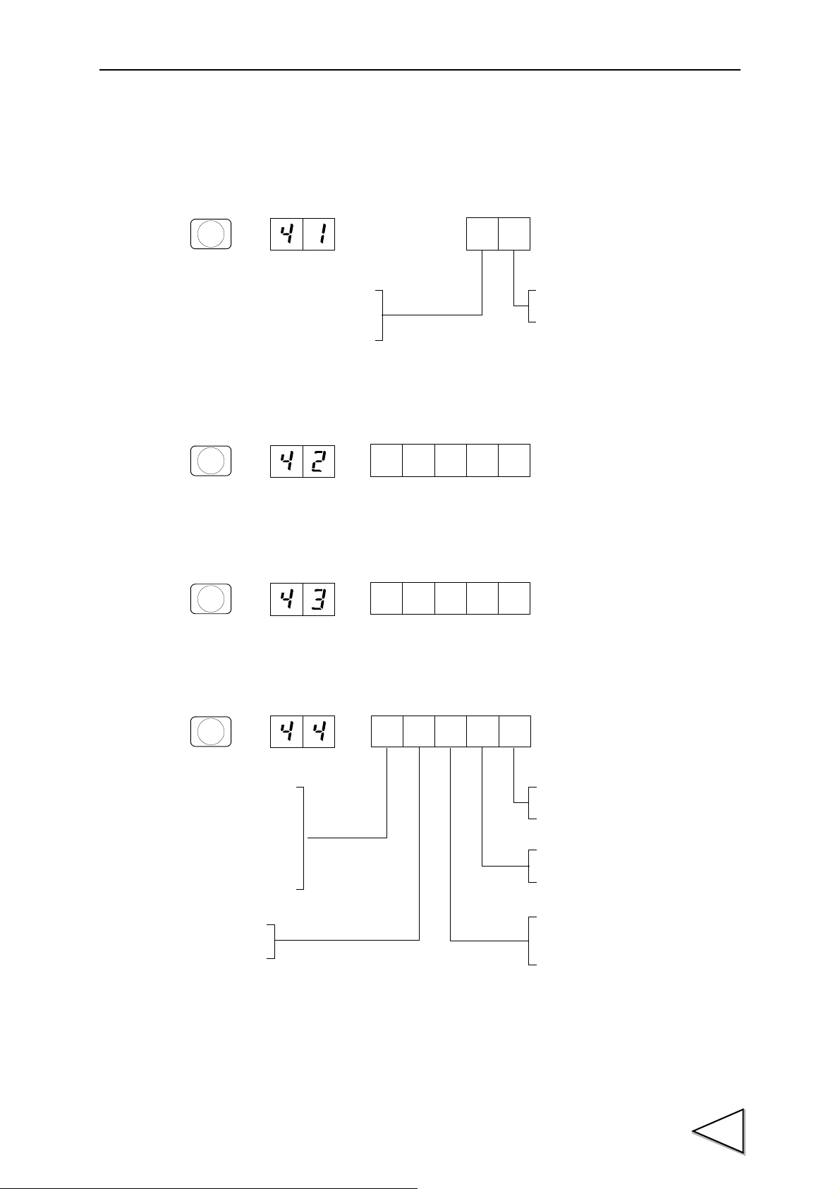
3-2-5. Setting Mode 4
Test mode
2 : 20mA fixed output
1 : 4mA fixed output
0 : Tied to the weight value
Output mode
1 : Net weight
0 : Gross weight
1
UPPER
(0 ~ 99999)
2
LOWER
(0 ~ 99999)
3
NEAR Z
.
Baud rate
5 : 38400bps
4 : 19200bps
3 : 9600bps
2 : 4800bps
1 : 2400bps
0 : 1200bps
Terminator
1 : CR+LF
0 : CR
Character length
1 : 8bit
0 : 7bit
Stop bit
1 : 2bit
0 : 1bit
Parity bit
2 : Even
1 : Odd
0 : None
4
SP1
In setting mode 4, setting values relating to communication are to be set.
- D/A Output Mode
(For details, please refer to "10-4-3" on P.143.)
- D/A Zero Output Weight
3.METHODS OF SETTING
(For details, please refer to "10-4-3" on P.143.)
- D/A Full Scale
(For details, please refer to "10-4-3" on P.143.)
- RS-485 I/F
(For details, please refer to "10-5-3" on P.147.)
33

3.METHODS OF SETTING
(0 ~ 9999)
5
SP2
Baud rate
5 : 38400bps
4 : 19200bps
3 : 9600bps
2 : 4800bps
1 : 2400bps
0 : 1200bps
Communication mode
7 : Communication mode 6
6 : Communication mode 5
5 : Communication mode 4
4 : Communication mode 3
3 : Communication mode 2
2 : Communication mode 1
1 : Communication mode 0
(CR + LF)
0 : Communication mode 0
(CR)
Character length
1 : 8bit
0 : 7bit
Stop bit
1 : 2bit
0 : 1bit
Parity bit
2 : Even
1 : Odd
0 : None
6
CPS
- ID Number
(For details, please refer to "10-5-4" on P.148.)
- RS-232C I/F
(For details, please refer to "10-2-3" on P.126.)
34

- External Function Selection
BCD data update rate
7 : 1 times/sec.
6 : 2 times/sec.
5 : 5 times/sec.
4 : 10 times/sec.
3 : 20 times/sec.
2 : 50 times/sec.
1 : 100 times/sec.
0 : 200 times/sec.
At discharging weighing time
1 : Net weight is displayed with
the sign not reversed.
0 : Net weight is displayed with
the sign reversed.
Filter in stable condition
1 : Not insert
0 : Insert (128 times)
Switching Gross weight/Net weight
1 : External input mode
0 : Internal key mode
1 : Checker mode
0 : Stable mode
Motion Detection mode
(For details, please refer to
"5-6" on P.58.)
(For details, please refer to
"5-15" on P.67.)
(For details, please refer to
"5-16" on P.68.)
(For details, please refer to
"5-5" on P.57.)
(For details, please refer to
"10-3-9" on P.140.)
display
7
OVER
8
UNDER
LOCK1
1 : ON
0 : OFF
LOCK2
1 : ON
0 : OFF
One-touch Tare subtraction
1 : Accept only at stable time
0 : Accept regularly
1 : Valid
0 : Invalid
Range of Tare subtraction
1 : 0 < Tare ≦ Capacity
0 : Total range
Prohibition of Tare Weight
1 : Valid
0 : Invalid
Tare Weight display with
the key
0
and digital tare subtraction
ON/OFF when one-touch
tare subtraction is working.
acceptance condition
9
FINAL
3.METHODS OF SETTING
- Setting Value LOCK
(For details, please refer to "8-1" on P.109.)
- Restriction on the Tare Subtraction Function
(For details, please refer to "5-14" on P.66.)
35

3.METHODS OF SETTING
Input selection 1 (B2 pin)
Input selection 3 (B4 pin)
6 : Accumulation Clear
5 : Accumulation Command
4 : Stop
3 : Start
2 : Feed/Discharge
1 : Judge
0 : HOLD
Input selection 2 (B3 pin)
1
UPPER
Input selection 4 (B5 pin)
6 : Accumulation Clear
5 : Accumulation Command
4 : Stop
3 : Start
2 : Feed/Discharge
1 : Judge
0 : HOLD
6 : Accumulation Clear
5 : Accumulation Command
4 : Stop
3 : Start
2 : Feed/Discharge
1 : Judge
0 : HOLD
6 : Accumulation Clear
5 : Accumulation Command
4 : Stop
3 : Start
2 : Feed/Discharge
1 : Judge
0 : HOLD
Output selection 3 (B11 pin)
1 : Accumulation Error
0 : RUN
Output selection 1 (B9 pin)
2 : Weight error
or sequence error
1 : Sequence error
0 : Weight error
Output selection 2 (B10 pin)
1 : Complete output
0 : Go output
2
LOWER
(For details, please refer to
"9-5-7" on P.119.)
(For details, please refer to
"6-11" on P.101.)
(For details, please refer to
"6-8" on P.93.)
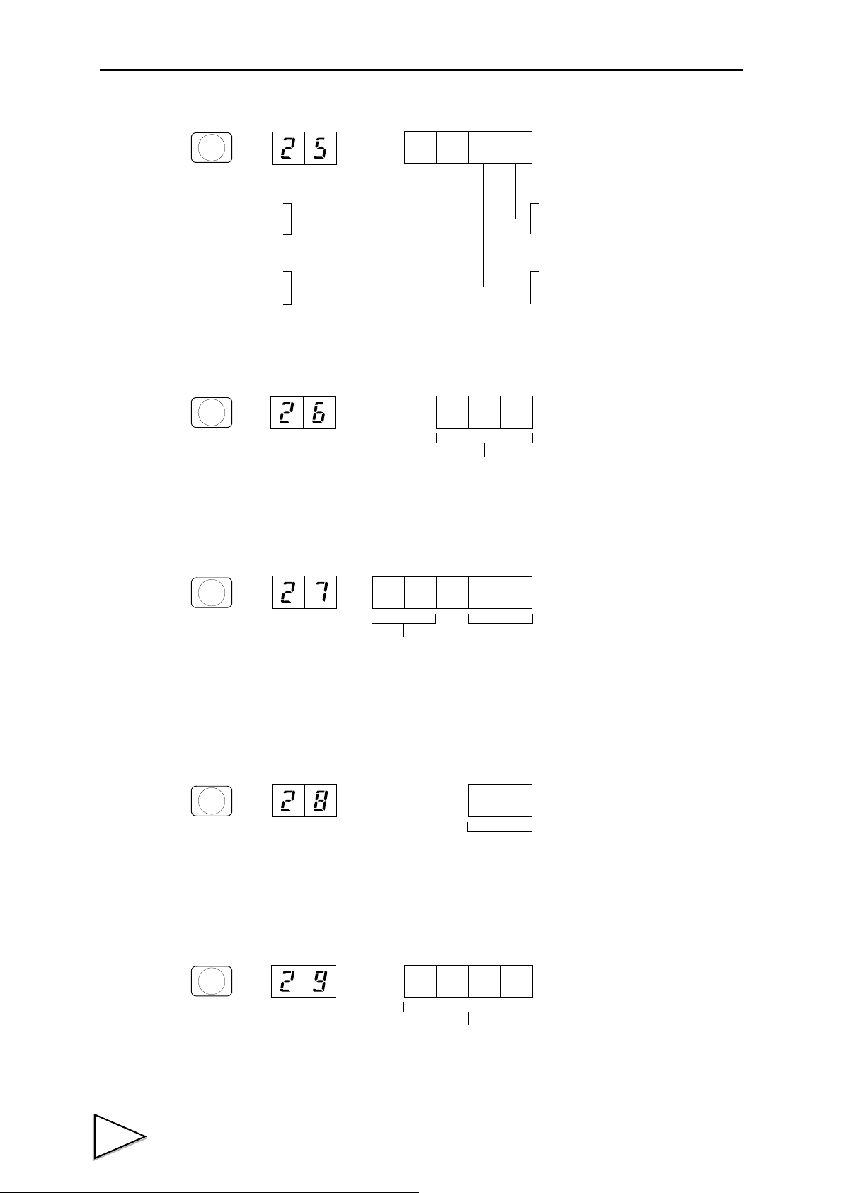
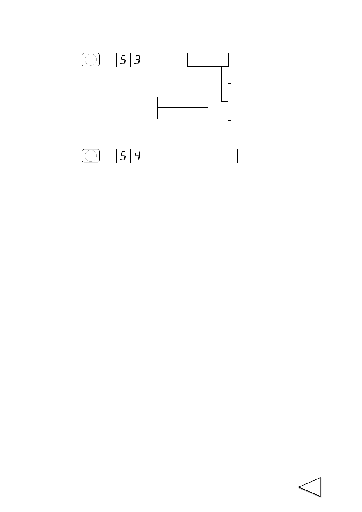
3-2-6. Setting Mode 5
- Input Selection
36
(For details, please refer to "9-4-11" on P.117.)
- Output Selection
3.METHODS OF SETTING
Transmission speed
4 : 10M
3 : 5M
2 : 2.5M
1 : 625k
0 : 156k
* Not defined
Number of occupied station
2 : Occupies 4 stations
1 : Occupies 2 stations
0 : Occupies 1 station
3
NEAR Z
(01 ~ 64)
4
SP1
- CC-Link I/F Number of occupied station & Transmission speed
- CC-Link I/F Station No.
37
3.METHODS OF SETTING
(0 ~ 99999)
1
UPPER
(0 ~ 99999)
2
LOWER
(0 ~ 99999)
3
NEAR Z
.
(0 ~ 99999)
4
SP1
(0 ~ 99999)
5
SP2
(0 ~ 10000)
6
CPS
(0 ~ 99999)
7
OVER
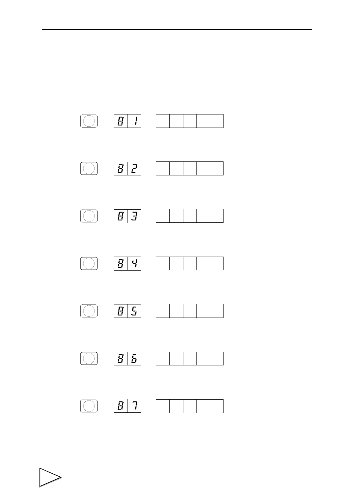
3-2-7. Setting Mode 8
In setting mode 8, statistical data having been accumulated in the F701-C is displayed, including
Average Weight, Max.Value, Min. Value, General Standard Deviation, Sample Standard Deviation,
Accumulation Count, Latest Accumulation Data, Max. - Min.
- Average Weight
- Max. Value
- Min. Value
- General Standard Deviation
- Sample Standard Deviation
- Accumulation Count (n)
38
- Latest Accumulation Data
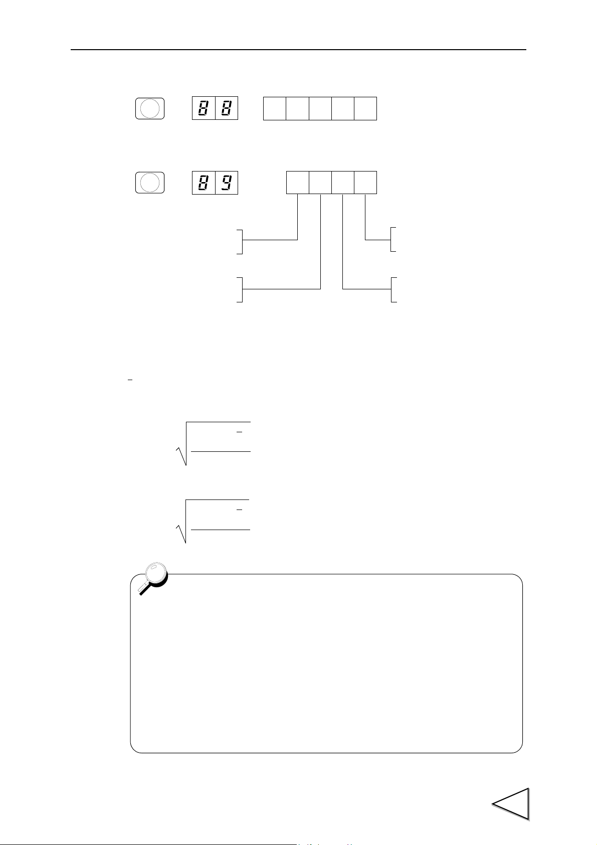
- Max. - Min. (R)
(0 ~ 99999)
8
UNDER
BCD parallel data
1 : Mounted
0 : Not mounted
output interface
1 : Mounted
0 : Not mounted
D/A converter
1 : Mounted
0 : Not mounted
RS-485 communication interface
9
FINAL
1 : Mounted
0 : Not mounted
CC-Link interface
σn =
Σ
n
i=1
n
(
χ
i
-
χ
)
2
Use all the data of the finite population and
find the standard deviation of the population.
σ
n-1
=
Σ
n
i=1
n-1
(
χ
i
-
χ
)
2
Use the sample data among the population and
the standard deviation of the population.
Data taking conditions
- When auto free fall compensation is OFF:
Data is taken when judgment is made.
- When auto free fall compensation is ON:
Data is taken when free fall compensation is made.
(Weighing Function 3 in setting mode 2)
- When the number of Judging Times is 00: No data is taken.
(Judging Time in setting mode 1)
* For judgment and auto free fall compensation, refer to "a) Judging Times"
on P.96.
- Optional Board
● Calculation Formula
3.METHODS OF SETTING
n = accumulation count = count of data
Σχ = accumulation = total amount
= average = accumulation / number of times = Σχ/ n
χ
General Standard Deviation
Sample Standard Deviation
39

3.METHODS OF SETTING
Accumulation clear
Statistical data is cleared by inputting the password “1235”.
(Please refer to "7-3.Accumulation Clear" on P.105.)
【Example】
Times Accumu
(n) lation weighing - Min. S.D. S.D.
Actual Average Max. Min. Max. General Sample
value
(Latest Accumulation Data)
0 0.000 0.000 0.000 0.000 0.000 0.000 error error
1 20.050 20.050 20.050 20.050 20.050 0.000 0.000 error
2 40.090 20.040 20.045 20.050 20.040 0.010 0.005 0.007
3 60.160 20.070 20.053 20.070 20.040 0.030 0.012 0.015
4 80.240 20.080 20.060 20.080 20.040 0.040 0.016 0.018
5 100.260 20.020 20.052 20.080 20.020 0.060 0.021 0.024
6 120.260 20.000 20.043 20.080 20.000 0.080 0.027 0.030
7 140.270 20.010 20.039 20.080 20.000 0.080 0.028 0.030
8 160.250 19.980 20.031 20.080 19.980 0.100 0.033 0.035
9 180.360 20.110 20.040 20.110 19.980 0.130 0.039 0.042
10 200.370 20.010 20.037 20.110 19.980 0.130 0.038 0.041
40

4. CALIBRATION
Connect F701-C to the load cell.....
?
?
?
The display is incorrect.....
100kg
100kg
After calibration.....
The F701-C and load cell
function as a weighing device.
4-1. Span Calibration
Calibration is performed for matching the F701-C to a load cell. For example, it is work to adjust so
that the F701-C accurately displays 100.00kg when an actual load (or weight) of 100kg is applied to
the load cell (balance section) of the weighing apparatus to which the F701-C is connected. This
operation is called Span Calibration.
4.CALIBRATION
41
4.CALIBRATION
Release Calibration LOCK
Decimal Place
Min. Scale Division
Capacity
Balance Weight Value
Zero Calibration
Span Calibration
Zero Calibration
Calibration LOCK
LOCK Switch OFF
LOCK Switch ON
Unit
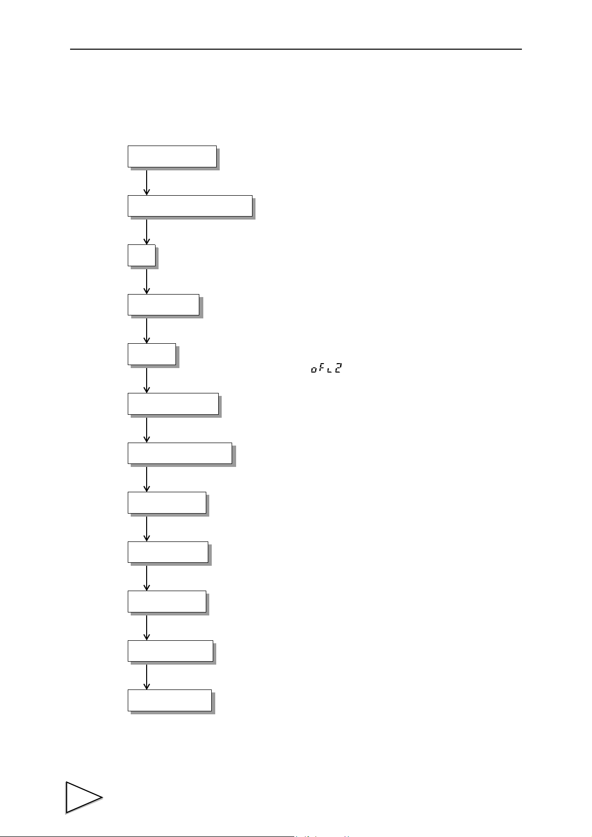
4-2. Span Calibration Procedure
Follow the steps below to perform Span Calibration.
Release calibration inhibit LOCK by the switch OFF on the rear
panel.
Release Setting Value LOCK which inhibits the calibration.
The displayed unit is set.
Register the position of decimal point.
Register the maximum capacity of the scale.
If the registered value exceeds by 9 scale divisions, display shows
over scale, “ ”.
Register the minimum unit (scale division) of the scale.
Register the value of load (balance weight) for load cell.
Calibrate the initial zero point.
Place the load (balance weight) on the load cell and register the
span value.
If it is necessary, re-calibrate initial zero point.
42
Disable changing setting value related to calibration.
Turn the calibration LOCK ON to prohibit the calibration for
avoiding false operation.

Release Calibration LOCK
Decimal Place
Min. Scale Division
Capacity
Balance Weight Value
Equivalent Calibration
Zero Calibration
Calibration LOCK
LOCK Switch OFF
LOCK Switch ON
*1
Unit
4.CALIBRATION
4-3. Secondary Calibration Procedure (Equivalent Calibration)
Calibration procedure performed by entering the rated output value (mV/V) and rated capacity
value of load cell without using real load.
Secondary calibration function is provided for provisional calibration when the F701-C develops
trouble or the calibration value is mistakenly changed.
The secondary calibration is only a provisional method. Calibration with actual load must be done
as soon as possible.
Release calibration inhibit LOCK by the switch OFF on the rear
panel.
Release Setting Value LOCK which inhibits the calibration.
The displayed unit is set.
Register the position of decimal point.
Register the maximum capacity of the scale.
If the registered value exceeds by 9 scale divisions, display shows
over scale, “ ”.
Register the minimum unit (scale division) of the scale.
Set the weight value corresponding to the output value to be
entered in *1.
Register the rated output value (mV/V) of load cell.
If it is necessary, re-calibrate initial zero point.
Disable changing setting value related to calibration.
Turn the calibration LCOK ON to prohibit the calibration for
avoiding false operation.
43

4.CALIBRATION
- Set the Balance Weight Value to the Capacity or less.
- For performing calibration at the rated value according to the specifications of
the load cell, set the Capacity to the same value as the rated value of the load
cell.
- When connecting several load cells in parallel, it is possible to occur some
differences between input and output value due to voltage drop caused by
connection or material of lines.
In this case, register actual input value to perform accurate calibration.
Request
44

4-4. Preparation for Calibration
Operation
LOCK
OFF
→→→
4
SP1
F
CNG/ENT CNG/ENT
→→ →
LOCK2
1 : ON
0 : OFF
8
UNDER
CNG/ENT CNG/ENT
ZERO
Concerning LOCK and setting values to be protected, refer to "18.THE LIST OF
INITIAL SETTING VALUE" on P.176.
4-4-1. LOCK Release
F701-C features a LOCK function for disabling changes in calibration and setting values.
The software LOCK is performed with the operation on the display; the hardware LOCK is located
on rear panel. Release both of locks when the calibration is performed.
1) LOCK OFF on the rear panel.
4.CALIBRATION
2) Select setting mode 4.
3) Set LOCK2 to OFF. (8-Setting Value LOCK)
LOCK is released through above procedure. After the calibration is finished, LOCK ON to protect
the calibration value.
45

4.CALIBRATION
Operation
Operation
→→→
F
CNG/ENT CNG/ENT
3
NEAR Z
.
Unit
5 : N 4 : lb
3 : kg 2 : g
1 : t 0 : None
→→
→
ZERO
7
OVER
CNG/ENT
ZERO ZERO
CNG/ENT
ZERO
→→→
F
CNG/ENT CNG/ENT
3
NEAR Z
.
Decimal place
→→ →
ZERO
7
OVER
CNG/ENTCNG/ENT
ZERO
3 :
2 :
1 :
0 :
In the F701-C, the decimal place is all fixed except for weight-related
descriptions.
* It cannot be changed.
4-4-2. Unit
Register the unit of the scale. The unit can select from t, kg, g, N, lb or None.
1) Select setting mode 3.
2) Select Unit. (7-Function Selection)
4-4-3. Decimal Place
Set the decimal place for weight-related displays, setting items, etc. Decimal place should be
selected from 0, 0.0, 0.00 or 0.000. This selection results in a common decimal place.
1) Select setting mode 3.
2) Select a desired decimal place. (7-Function Selection)
46

4.CALIBRATION
Operation
Operation
→→→
F
CNG/ENT CNG/ENT
3
NEAR Z
.
→→ →
Capacity
(0 ~ 99999)
2
LOWER
CNG/ENT CNG/ENT
→→→
F
CNG/ENT CNG/ENT
3
NEAR Z
.
→→ →
Min. Scale Division
(1 ~ 100)
CNG/ENT CNG/ENT
3
NEAR Z
.
4-4-4. Capacity
Register the maximum capacity of the scale. If the registered value exceeds by 9 scale divisions,
display shows over scale, “ ”. (Input range / 0 ~ 99999)
1) Select setting mode 3.
2) Input the Capacity. (2-Capacity)
4-4-5. Minimum Scale Division
Register the minimum unit (scale division) of the scale. (Input range / 1 ~ 100)
1) Select setting mode 3.
2) Input the Min. Scale Division. (3-Min. Scale Division)
47

4.CALIBRATION
Operation
Operation
→→→
F
CNG/ENT CNG/ENT
3
NEAR Z
.
→→ →
Balance Weight Value
(0 ~ 99999)
1
UPPER
CNG/ENT CNG/ENT
→→→
F
CNG/ENT CNG/ENT
3
NEAR Z
.
→→ →
Area number
(0 ~ 16)
8
UNDER
CNG/ENT CNG/ENT
4-4-6. Balance Weight Value
Register the value of load (balance weight) before the Span Calibration.
(Input range / 0 ~ 99999)
1) Select setting mode 3.
2) Input the Balance Weight Value. (1-Balance Weight Value)
4-4-7. Gravitational Acceleration
If the calibration location and installation location of the balance are different, correct the
gravitational error resulting from an area-to-area difference in gravitational acceleration by this
function.
If the calibration location and installation location are in the same area, this setting is not needed.
Find the area number (01 ~ 16) of the area where actual load calibration is carried out from the
Gravitational Acceleration correction table on the next page, set the number, and then perform
actual load calibration.
Next, find the actual installation area from the table, and input the area number. Now, the difference
from the calibration location in gravitational acceleration is corrected.
Also, if the area number is set at 00, Gravitational Acceleration (acceleration input) becomes valid.
1) Select setting mode 3.
2) Input the Area number. (8-Gravitational Acceleration : area number input)
48

3) If the Area number is set at 00, input Acceleration.
→→ →
Acceleration
(9.700 ~ 9.999)
9
FINAL
CNG/ENT CNG/ENT
If the area number is set at 00, Gravitational Acceleration (Acceleration input)
becomes valid.
Amsterdam 9.813m/s
2
Ottawa 9.806m/s
2
Athens 9.800m/s
2
Paris 9.809m/s
2
Auckland NZ 9.799m/s
2
Rio de janeiro 9.788m/s
2
Bangkok 9.783m/s
2
Rome 9.803m/s
2
Birmingham 9.813m/s
2
San Francisco 9.800m/s
2
Brusseles 9.811m/s
2
Singapore 9.781m/s
2
Buenos Aires 9.797m/s
2
Stockholm 9.818m/s
2
Calcutta 9.788m/s
2
Sydney 9.797m/s
2
Capetown 9.796m/s
2
Taichung 9.789m/s
2
Chicago 9.803m/s
2
Tainan 9.788m/s
2
Copenhagen 9.815m/s
2
Taipei 9.790m/s
2
Cyprus 9.797m/s
2
Tokyo 9.798m/s
2
Djakarta 9.781m/s
2
Vancouver,BC 9.809m/s
2
Frankfurt 9.810m/s
2
Washinton DC 9.801m/s
2
Glasgow 9.816m/s
2
Wellington NZ 9.803m/s
2
Havana 9.788m/s
2
Zurich 9.807m/s
2
Helsinki 9.819m/s
2
Kuwait 9.793m/s
2
Lisbon 9.801m/s
2
London (Greenwich) 9.812m/s
2
Los Angelse 9.796m/s
2
Madrid 9.800m/s
2
Manila 9.784m/s
2
Melbourne 9.800m/s
2
Mexico City 9.779m/s
2
Milan 9.806m/s
2
New York 9.802m/s
2
Oslo 9.819m/s
2
(9-Gravitational Acceleration : acceleration input)
Gravitational acceleration correction table
01 9.806 02 9.805 03 9.804 04 9.803
05 9.802 06 9.801 07 9.800 08 9.799
09 9.798 10 9.797 11 9.796 12 9.795
13 9.794 14 9.793 15 9.792 16 9.791
4.CALIBRATION
49

4.CALIBRATION
Operation
ZERO
→→→
F
CNG/ENT CNG/ENT
3
NEAR Z
.
→→ →
1/4 scale division display
1 : ON
0 : OFF
ZERO
7
OVER
CNG/ENTCNG/ENT
ZERO ZERO
nn+1
1/4 scale
Min. Scale Division
ON
“ ”
(1scale divisio)
ZERO
ON
“ ”
ZERO
When the 1/4 scale division setting is OFF, “ “ lamp only works at the zero
point.
ZERO
-1
1/4 scale
0
1
ON
“ ”
ZERO
4-4-8. 1/4 Scale Division
It divides the minimum scale division into four (4) parts. The “ ” (center zero) lamp turns on
when the weight is between +1/4 division and -1/4 division.
1/4 scale division selects ON/OFF.
1) Select setting mode 3.
2) Select 1/4 scale division display ON/OFF. (7-Function Selection)
50

4-5. Zero Calibration
Operation
STAB
9
FINAL
→→→
F
CNG/ENT CNG/ENT
kg
,
In-zero-calibration display.
The in-calibration display differs
according to the pre-calibration condition.
→
ZERO
CNG/ENT
,
kg
Weight value
Setting mode number
Register initial zero point.
- Verify there are no excess loads applied to load cell (or scale).
- Check that “ ” is ON. (Correct calibration can not be completed if signal is unstable.)
1) Select setting mode 9 (Calibration mode).
2) Register the Zero point.
4.CALIBRATION
3) When the weight value display becomes 0, Zero Calibration is completed.
If a calibration error is displayed, redo Zero Calibration corresponding to the following error
messages. (Please refer to "11.OVER SCALE & ERROR" on P.157.)
- “ ”
Initial dead load is above zero adjustment range.
Remove any excess load from load cell or scale. If is still displayed, connect a
resistor between +EXC and -SIG load cell connections. This should shift the zero point.
51

4.CALIBRATION
- This table is for a 350 Ω load cell.
- The temperature coefficient of the connected resistor directly influences the accuracy
of the controller. Use a resistance having a temperature coefficient of 50ppm/ ℃ or
more (recommended value of about 5ppm/ ℃ ).
Resistance Strain
Calculated value Approx.value μ-STRAIN mV/V
875 kΩ
437 kΩ
291 kΩ
219 kΩ
175 kΩ
146 kΩ
125 kΩ
109 kΩ
97 kΩ
87.3 kΩ
79.4 kΩ
72.7 kΩ
67.1 kΩ
62.3 kΩ
58.2 kΩ
54.5 kΩ
51.3 kΩ
48.4 kΩ
45.9 kΩ
43.6 kΩ
41.5 kΩ
39.6 kΩ
37.9 kΩ
36.3 kΩ
34.8 kΩ
866 kΩ
442 kΩ
294 kΩ
221 kΩ
174 kΩ
147 kΩ
124 kΩ
110 kΩ
97.6 kΩ
86.6 kΩ
78.7 kΩ
73.2 kΩ
66.5 kΩ
61.9 kΩ
57.6 kΩ
54.9 kΩ
51.1 kΩ
48.7 kΩ
46.4 kΩ
43.2 kΩ
41.2 kΩ
39.2 kΩ
38.3 kΩ
36.5 kΩ
34.8 kΩ
200
400
600
800
1000
1200
1400
1600
1800
2000
2200
2400
2600
2800
3000
3200
3400
3600
3800
4000
4200
4400
4600
4800
5000
0.1
0.2
0.3
0.4
0.5
0.6
0.7
0.8
0.9
1.0
1.1
1.2
1.3
1.4
1.5
1.6
1.7
1.8
1.9
2.0
2.1
2.2
2.3
2.4
2.5
52
- “ ”
Inditial dead load is negative.
Check that load cell is mounted in the correct direction; check that load is being applied to
the load cell in the correct direction; check that the +SIG and -SIG lines are propely
connected.
If still displayed, connect a resistor between -EXC and -SIG load cell
connections. This should shift the zero point. Do Zero Calibration again.
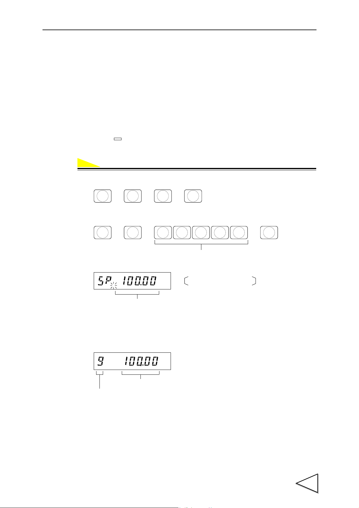
4-6. Span Calibration
Operation
STAB
→→→
F
CNG/ENT CNG/ENT
9
FINAL
In-span-calibration display.
The in-calibration display differs according to the pre-calibration condition.
(The previous setting value, etc., is displayed.)
Balance Weight Value
(0 ~ 99999)
→→ →
1
UPPER
CNG/ENT CNG/ENT
kg
,
Weight value
Setting mode number
kg
Span Calibration means putting a load (test weight) on the load cell (or scale) and calibrating so the
F701-C indicates correct weight.
- Put the Balance Weight Value which is set the Balance Weight Value, on the load cell (or scale).
(Calibrating with more than 50% of the Capacity is favorable in respect of linearity.)
- Verify there are no excess loads applied to load cell (or scale).
- Check that “ ” is on. (Correct calibration can not be completed if signal is unstable.)
1) Select setting mode 9 (Calibration mode).
4.CALIBRATION
2) Perform Span Calibration. (1-Span Calibration)
3) When the weight value display becomes equal to the Balance Weight Value, Span Calibration is
completed.
* If any error message appears, refer to "11.OVER SCALE & ERROR" on P.157.
53

4.CALIBRATION
Operation
→→→
F
CNG/ENT CNG/ENT
3
NEAR Z
.
→→ →
Balance Weight Value
(0 ~ 99999)
1
UPPER
CNG/ENT CNG/ENT
→→→
F
CNG/ENT CNG/ENT
9
FINAL
→→ →
Output value of the load cell
(0.5000 ~ 3.2000)
2
LOWER
CNG/ENT CNG/ENT
4-7. Secondary Calibration (Equivalent Calibration)
By key-inputting the weight value corresponding to the output value (mV/V) of the load cell,
calibration is performed so that the input of the entered output value results in the entered weight
value display.
1) Select setting mode 3.
2) Input the Balance Weight Value corresponding to the output value to be entered in 4).
(1-Balance Weight Value)
3) Select setting mode 9.
4) Input the Output value of the load cell. (2-Equivalent Calibration)
* If any error message appears, refer to "11.OVER SCALE & ERROR" on P.157.
* If “ ” (Zero Calibration again) appears, redo Zero Calibration, and then perform
Equivalent Calibration again.
* “ ” is displayed when calibrating by resolution that exceeds 1/10000.
54

5. FUNCTION SETTINGS
Operation
→→→
F
CNG/ENT CNG/ENT
3
NEAR Z
.
Display frequency
3 : 25 times/sec.
2 : 13 times/sec.
1 : 6 times/sec.
0 : 3 times/sec.
→→ →
ZERO
7
OVER
CNG/ENT CNG/ENT
5-1. Display Frequency
Select the F701-C display frequency. The numbers of updates on the display per second is only
selected here.
Internal A/D conversion speed and CPU processing speed are not changed. The available display
frequencies are: 25, 13, 6 or 3 times/sec.. 25 times/sec. is recommended for normal operation.
If the display flickers, select a lower frequency.
1) Select setting mode 3.
5.FUNCTION SETTINGS
2) Select Display frequency. (7-Function Selection)
55
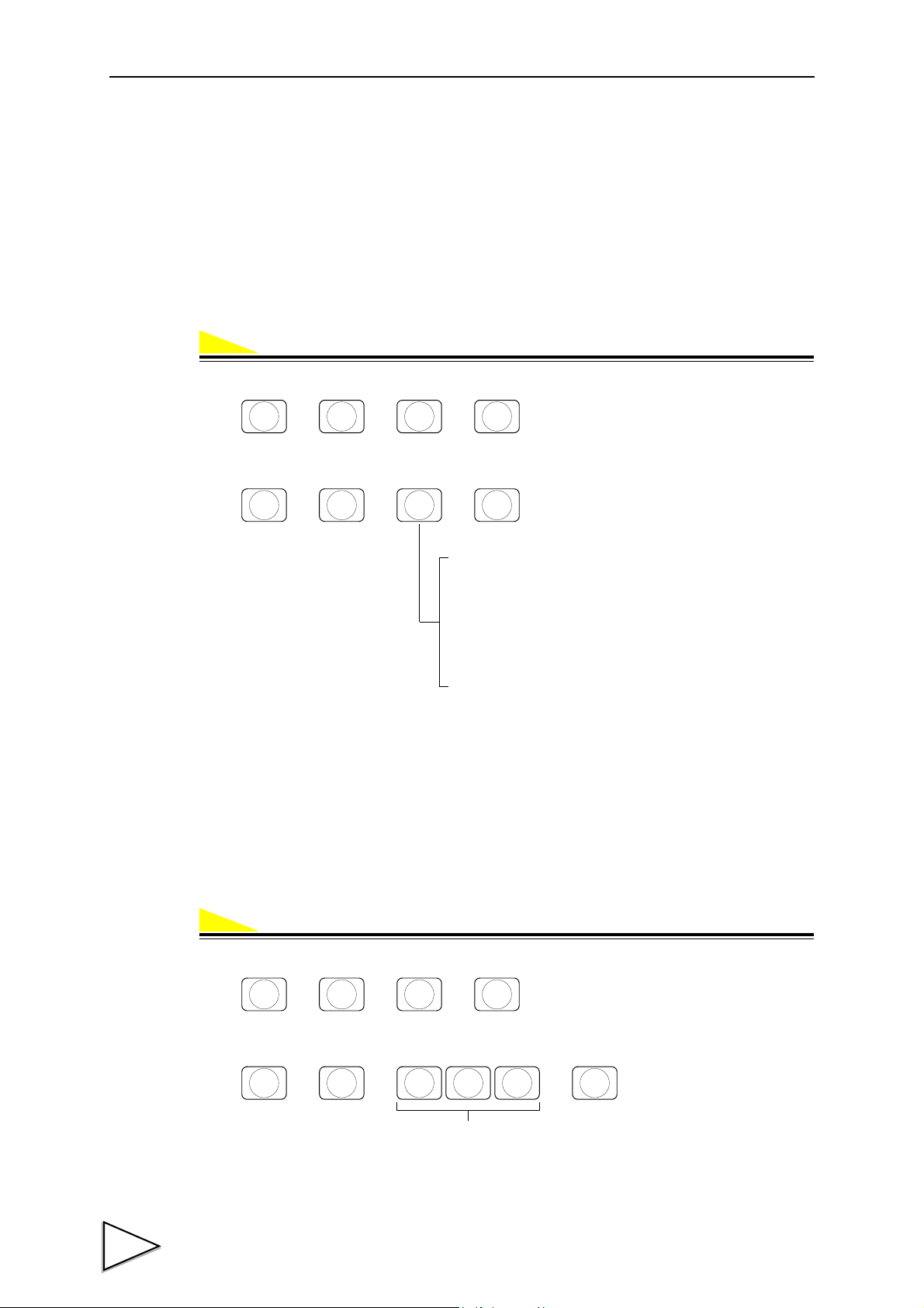
5.FUNCTION SETTINGS
Operation
Operation
→→→
F
CNG/ENT CNG/ENT
3
NEAR Z
.
Subdisplay selection
5 : Near Zero / Upper Limit / Lower Limit
4 : Final / Over / Under
3 : Accumulation Count / Latest Accumulation Data /
Final
2 : Latest Accumulation Data / Accumulation Value
1 : Accumulation Count / Accumulation Value
0 : None
→→→
7
OVER
CNG/ENT CNG/ENT
→→→
F
CNG/ENT CNG/ENT
2
LOWER
→→ →
Digital Filter (times)
(0 ~ 256)
6
CPS
CNG/ENTCNG/ENT
5-2. Subdisplay Selection
Set the data to be displayed in the subdisplay area.
What is displayed in the subdisplay area is the data set here out of:
Near Zero/Upper Limit/Lower Limit; Final/Over/Under; Accumulation Count/Latest Accumulation
Data/Final; Latest Accumulation Data/Accumulation Value; Accumulation Count/Accumulation
Value; and None.
(For details, please refer to "1-1.Front Panel" ② Subdisplay on P.1.)
1) Select setting mode 3.
2) Select the data to be displayed. (7-Function Selection)
5-3. Digital Filter
This function minimizes instability of the weight value by calculating the average frequency of the
data converted from analog to digital. The frequency of the moving average selected from OFF(0) ~
256 times. A higher frequency will make a more stable display with slower response.
A lower frequency will have quicker response but more unstable display.
Select the most suitable value for the weighing.
1) Select setting mode 2.
2) Input the frequency of moving averages. (6-Digital Filter)
56

5-4. Analog Filter
Operation
Operation
→→→
F
CNG/ENT CNG/ENT
1
UPPER
Analog Filter
3 : 8Hz
2 : 6Hz
1 : 4Hz
0 : 2Hz
→→→
8
UNDER
CNG/ENT CNG/ENT
Load cell
Analog
Filter
A/D
Digital
Filter
Digital
Filter
F701-C
OFF
Stab OFF or filter is not
Setting counts Stable
("5-3.Digital Filter"
on P.56)
inserted in stable condition.
(128 Count fixed)
Setting frequency
("5-4.Analog Filter"
on P.57)
converter
→→→
F
CNG/ENT CNG/ENT
4
SP1
Filter in stable condition
1 : Not insert
0 : Insert (128 times)
→→ →
ZERO
7
OVER
CNG/ENT CNG/ENT
This function stabilizes the display by removing low frequency noise from the load cell signal as
well as averaging analog signals.
Selectable frequencies are: 2, 4, 6 or 8Hz. A higher frequency will make a more quick response but
sometimes read a noise in.
Select the most suitable value for the weighing.
1) Select setting mode 1.
2) Select cutoff frequency. (8-Analog Filter)
5.FUNCTION SETTINGS
5-5. Filter in Stable Condition
When indicated value is stable, this function automatically insert the Digital Filter for restraining
the instability. Select whether inserts it or not.
Regarding the definition of stability, refer to "5-6.Motion Detection (MD)" on P.58.
1) Select setting mode 4.
2) Select whether or not to insert the filter. (7-External Function Selection)
57
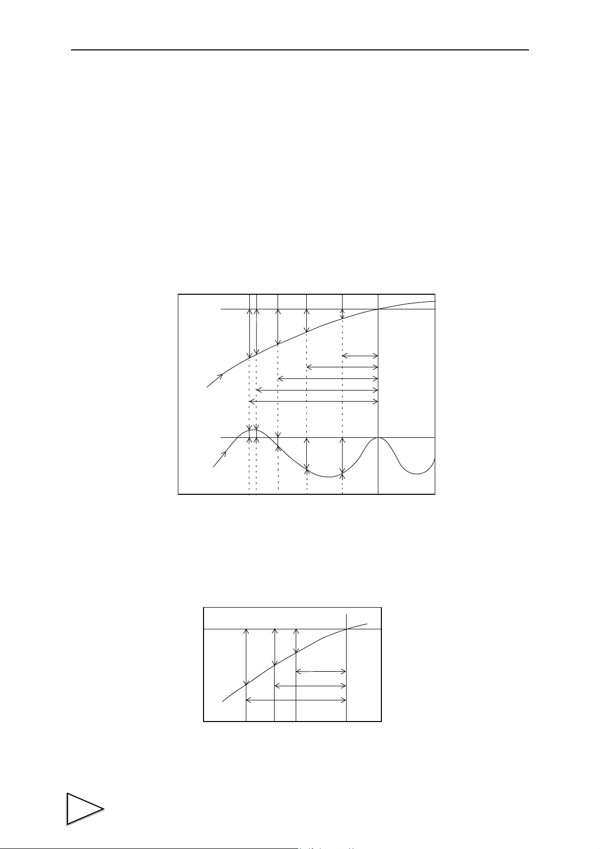
5.FUNCTION SETTINGS
D1
D2
D3
D4
D5
D1 D2
D3
D4
D5
0.3
0.6
0.8
0.95
1.00 sec.
Weight value
Weight value
〈e.g.1〉
〈e.g.2〉
D1
D2
D3
0.03
0.06
0.09 sec.
5-6. Motion Detection (MD)
Set the parameter to detect the stability of the indicated value.
When the range of weight changes is within the set range and the status lasts for set period of time,
the Stab. turns ON considering to be the weight stable.
There are stable mode and checker mode in Motion Detection.
Stable mode
D1 ~ D5 shown below are compared with a set range at each A/D conversion.
* D1 represents the difference between current weight value and the value 1 second previous. If
one of them exceeds the range, the Stab. turns OFF at once.
58
Checker mode
D1 ~ D3 shown below are compared with a set range at each A/D conversion.
If one of them exceeds the range, the Stab. turns OFF at once.
* D1 represents the difference between current weight value and the value 0.09 second previous.
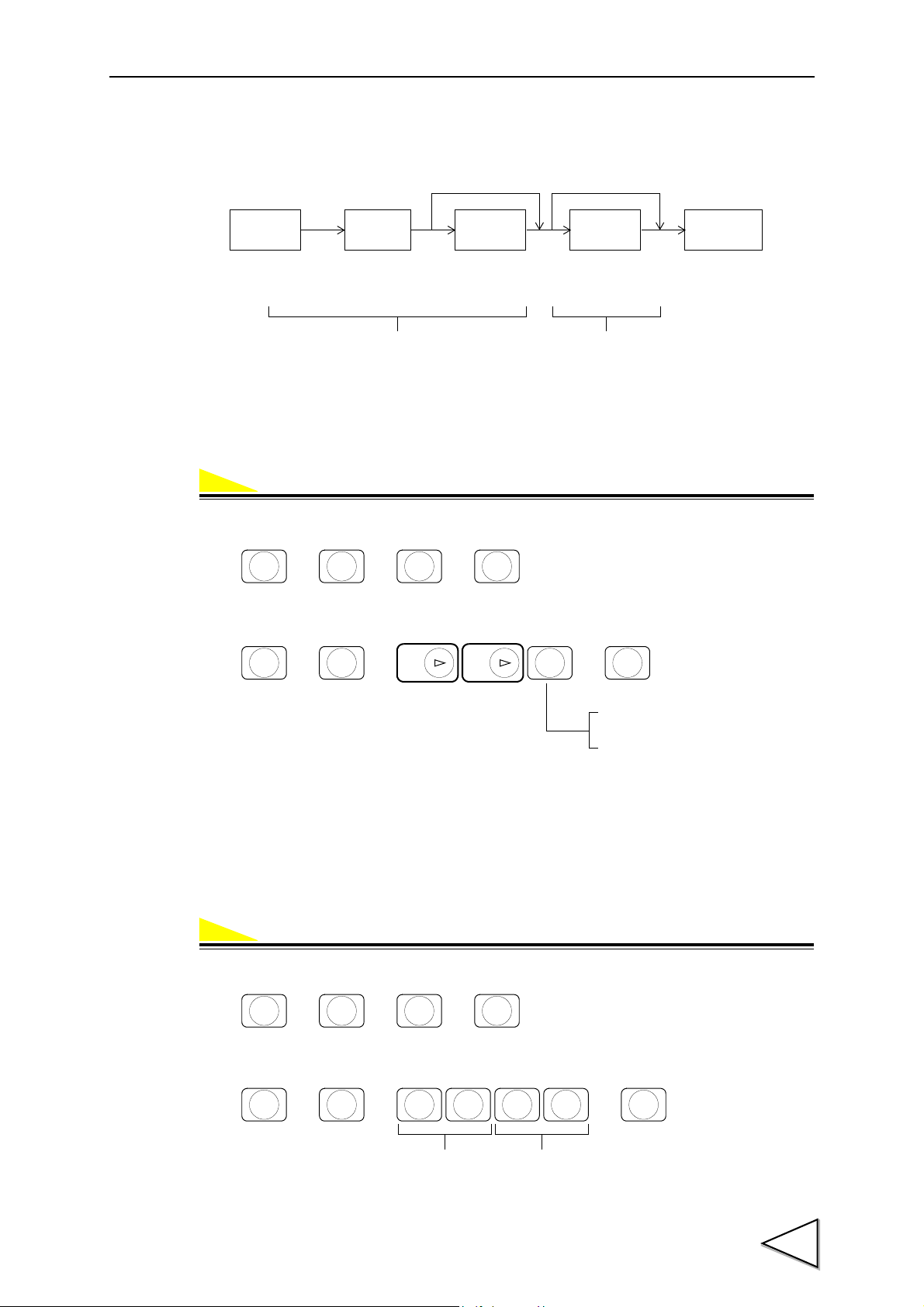
5.FUNCTION SETTINGS
Operation
Operation
Analog
Filter
A/D
Digital
Filter
Digital
Filter
Comparator
OFF Stab OFF
Cutoff
frequency selectable
(2,4,6,8 Hz)
Counts selectable
(0
~ 256 Times)
Stab. ON
(128 Times fixed)
Set under Analog Filter in setting mode 1,
and Digital Filter in setting mode 2.
Set ON/OFF under External Function
Selection in setting mode 4.
→→→
F
CNG/ENT CNG/ENT
4
SP1
Motion Detection mode
1 : Checker mode
0 : Stable mode
→→ →
ZERO
7
OVER
CNG/ENT CNG/ENT
ZERO
→→→
F
CNG/ENT CNG/ENT
2
LOWER
Period (sec.)
(0.0 ~ 9.9)
Range
(0 ~ 99)
→→ →
7
OVER
CNG/ENT CNG/ENT
When the Stab. is ON, it enables to insert the Digital Filter to restrain the instability of weight
value. (Please refer to "5-5.Filter in Stable Condition" on P.57.)
Setting motion detect parameter
MD mode Select the stable condition from stable mode or checker mode.
1) Select setting mode 4.
2) Select a desired mode. (7-External Function Selection)
MD period Setting the period for judging the stability of weight.
(Input range / 0.0 ~ 9.9)
MD range Comparing the value (setting value×minimum scale division) with the range of
weight change.
(Input range / 0 ~ 99)
1) Select setting mode 2.
2) Input the Period and Range. (7-Motion Detection)
59
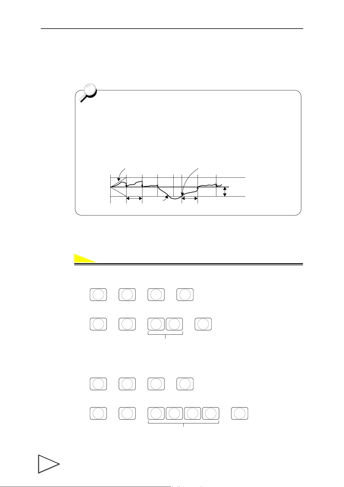
5.FUNCTION SETTINGS
Operation
- Zero Tracking adjusts the zero point every set period when the shifting of the
zero point is within the set point.
- The Tracking Period must be set between 0.0 and 9.9 seconds. The Tracking
Range (digit) must be set from 0 ~ 9999 using a 1/4 scale division as a unit.
(0002=0.5 divisions, 0012=3 divisions)
Zero Tracking does not work when the period is set 0.0 or the range is set to
00.
Boundary of zero track
Tracking period
Weighing value
Tracking range
+
0
-
Tracking period
From the point when it returned within the range,
counting will be resumed.
→→→
F
CNG/ENT CNG/ENT
2
LOWER
Period (sec.)
(0.0 ~ 9.9)
→→ →
8
UNDER
CNG/ENT CNG/ENT
→→→
F
CNG/ENT CNG/ENT
2
LOWER
→→ →
Range
(0 ~ 9999)
9
FINAL
CNG/ENT CNG/ENT
5-7. Zero Tracking (ZT)
This function automatically adjusts slow drifts and slight shifting of the zero point due to small
amounts of accumulation on a scale.
a) Zero Tracking Period (Input range / 0.0 ~ 9.9)
b) Zero Tracking Range (Input range / 0 ~ 9999)
a)
1) Select setting mode 2.
2) Input the Zero Tracking Period. (8-Zero Tracking Period)
b)
1) Select setting mode 2.
2) Input the Zero Tracking Range. (9-Zero Tracking Range)
60

5-8. Digital Zero (DZ)
Operation
ZALM
ZERO
CNG/ENT
OFF
ON
Pulse width 50msec or more
ZALM
The Gross weight is forcibly zeroed by this function. The Net weight changes according to the
following expression: (Net weight) = (Gross weight) - (Tare weight).
If the digital zero operation is performed where Gross weight exceeds the DZ Regulation Value
(Please refer to "5-10.Zero Regulation Value" on P.62.), “ ” flashes to give a warning of the
problem.
In this case DZ Regulation Value is subtracted from Gross weight.
1) Press → .
2) Gross is zeroed.
5.FUNCTION SETTINGS
- Digital zero by external signal
By short-circuiting A3pin (D/Z ON) and COM on the control connector, Gross weight is
immediately zeroed.
Net weight changes according to the following expression:
(Net weight) = (Gross weight) - (Tare weight).
* In a case where 0 is not indicated when performing digital zero operation or when “ ”
flashes, the following causes are considered.
Cause Measure
Digital zero operation was performed
when the DZ Regulation Value
(default value 200) was exceeded.
- Change the set value of the DZ Regulation
Value and perform digital zero operation
again. (However, since this is a temporary
measure, perform Zero Calibration at an
early time.)
- Remove lightweight residue adhered to the
tank.
- Check that there is no mechanical contact.
61

5.FUNCTION SETTINGS
Operation
Operation
ZALM
ZALM
→→→
F
CNG/ENT CNG/ENT
9
FINAL
ZALM
→→→
F
CNG/ENT CNG/ENT
3
NEAR Z
.
→→ →
DZ Regulation Value
(0 ~ 9999)
6
CPS
CNG/ENT CNG/ENT
5-9. Digital Zero Clear
This function clears the digital zero.
If this operation is performed when “ ” flashes, the digital zero is cleared, and “ ” goes
out.
1) By selecting setting mode 9 (Calibration mode), the digital zero is cleared.
5-10. Zero Regulation Value
Set a range of zero point adjustment (a gap from the registered Zero Calibration value) by digital
zero or zero tracking.
If the digital zero operation is performed or zero tracking operates where the DZ Regulation Value
is exceeded, “ ” flashes to give a warning of the problem.
(Input range / 0 ~ 9999)
1) Select setting mode 3.
2) Input the DZ Regulation Value. (6-DZ Regulation Value)
62

5-11. One-touch Tare Subtraction
Operation
TARE
STAB
TARE
TARE
TARE
OFF
ON
Pulse width 50msec or more
GROSS
/NET
ESC
NET
STAB
Tare is subtracted and Net weight is zeroed by pressing key.
However, the operation is performed only when “ ” is on depending on the setting of
Restriction on the Tare Subtraction Function in setting mode 4. The range of Tare subtraction can be
selected from all range or 0 < Tar e ≦ Capacity.
1) Press .
2) “ ” lights.
- Tare subtraction by external signal
5.FUNCTION SETTINGS
By short-circuiting A4pin (Tare subtraction ON) and COM on the control connector, Net weight is
immediately zeroed, and “ ” lights.
* If Net weight is not zeroed by performing the operation of Tare subtraction, the following causes
are presumable.
Cause Measure
The indicated value is Gross weight.
Press the key to change the
indicated value into Net weight.
(If “ ” is on, the indicated value is Net
weight.)
The indicated value is not stable.
(By setting)
Perform the operation of Tare subtraction
when “ ” is ON.
The indicated value is out of the
range of Tare subtraction.
(By setting)
Perform the operation of Tare subtraction in
the range of Tare subtraction.
63

5.FUNCTION SETTINGS
Operation
TARE
RESET
TARE
TARE
OFF
ON
Pulse width 50msec or more
5-12. One-touch Tare Subtraction Reset
The subtracted Tare can be restored and Net weight becomes equal to Gross weight.
1) Press .
2) “ ” goes out.
- Tare subtraction reset by external signal
By short-circuiting A5pin (Tare subtraction OFF) and COM on the control connector, Tare
subtraction is immediately reset, and Net weight and Gross weight are equalized.
“ ” goes out.
* If Net weight and Gross weight are not equalized by resetting Tare subtraction, the following
cause is presumable.
Cause Measure
The digital tare subtraction
function is valid.
Set the value of Tare Weight in setting mode
1 to 0, or set digital tare subtraction
ON/OFF in setting mode 2 to OFF.
64
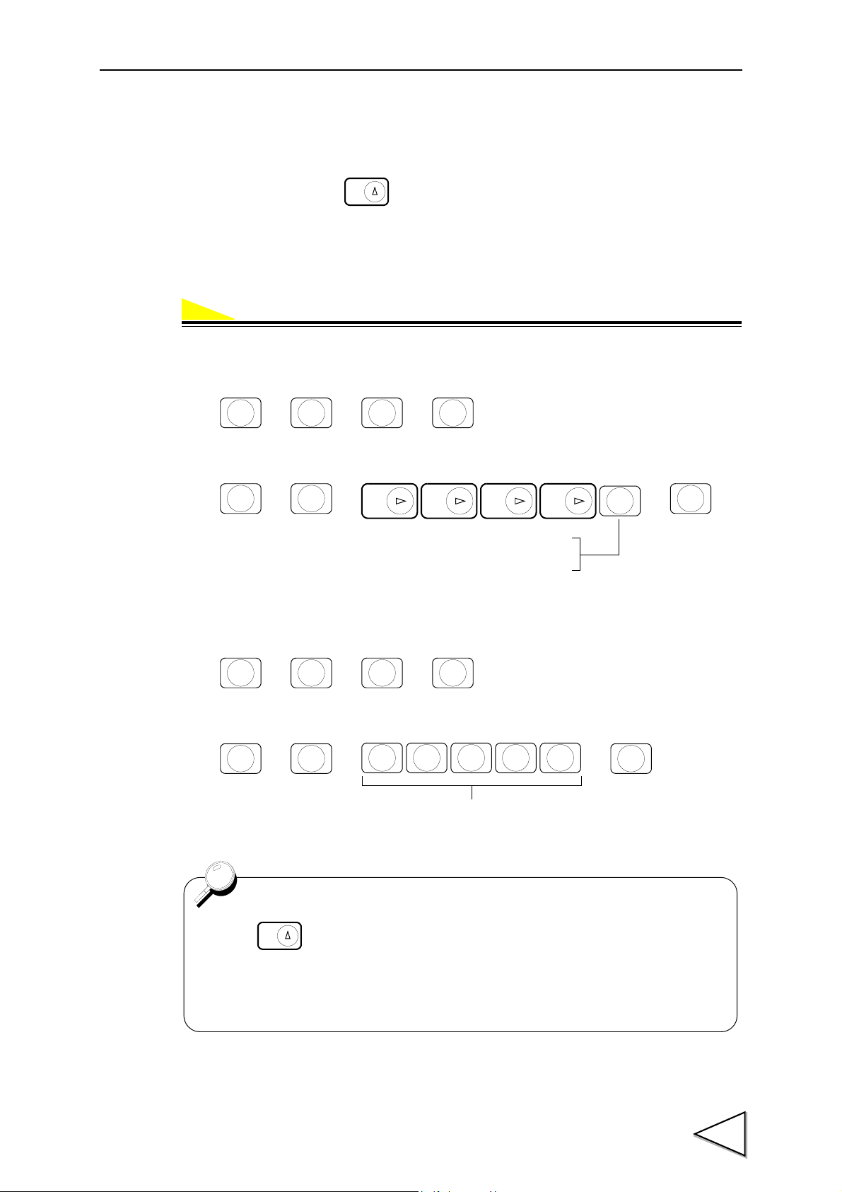
5-13. Digital Tare Subtraction
Operation
TARE
→→→
F
CNG/ENT CNG/ENT
2
LOWER
1 : Digital tare subtraction ON
0 : Digital tare subtraction OFF
→→ →
ZERO
CNG/ENT CNG/ENT
ZERO ZERO
3
NEAR Z
.
ZERO
→→→
F
CNG/ENT CNG/ENT
1
UPPER
→→ →
Tare We i g h t
(0 ~ 99999)
9
FINAL
CNG/ENT CNG/ENT
Tare subtraction and digital tare subtraction functions independently.
When is pressed, tare subtraction will be executed at once then Net
weight becomes 0 while digital tare subtraction is ON.
However, when tare subtraction is active in Restriction of the Tare Subtraction
Function, ON/OFF in digital tare subtraction and Tare Weight maybe invalid.
TARE
Tare is subtracted and Net weight is zeroed.
Set Tare Weight by pressing key then set digital tare subtraction ON.
a) Digital tare subtraction (Select from ON/OFF)
b) Tare Weight (Input range / 0 ~ 99999)
a)
1) Select setting mode 2.
2) Select Digital tare subtraction ON/OFF. (3-Weighing Function 3)
5.FUNCTION SETTINGS
b)
1) Select setting mode 1.
2) Input the Tare Weight. (9-Tare Weight)
65

5.FUNCTION SETTINGS
Operation
0
0
→→→
F
CNG/ENT CNG/ENT
4
SP1
One-touch Tare subtraction
1 : Accept only at stable time
0 : Accept regularly
1 : Valid
0 : Invalid
Range of Tare subtraction
1 : 0 < Tare ≦ Capacity
0 : Total range
Prohibition of Tare Weight
1 : Valid
0 : Invalid
Tare Weight display with
the key
0
and digital tare subtraction
ON/OFF when one-touch
tare subtraction is working.
acceptance condition
→→ →
9
FINAL
CNG/ENT CNG/ENT
5-14. Restriction of the Tare Subtraction Function
It can be restricted the function of digital tare subtraction or one touch tare subtraction.
a) One-touch tare subtraction (Select from Regularly / In stable mode)
acceptance condition It displays the timing of the Tare subtraction.
b) Range of tare subtraction (Whole range or from 0 < Tare ≦ Capacity)
c) Tare Weight display with (Select from Valid / Invalid)
the key If it is set to be valid, the Tare Weight is displayed
at the weight display section by pressing .
d) Digital tare subtraction (Select from Valid / Invalid)
expansion (Prohibition of Tare Weight and digital tare subtraction
ON/OFF when one-touch tare subtraction is working.)
Select valid for inhibiting Tare Weight and digital tare
subtraction ON/OFF when tare subtraction is in operation.
66
a), b), c), d)
1) Select setting mode 4.
2) Put restrictions on the above four items.
(9-Restriction of the Tare Subtraction Function)

5-15. Switching Gross Weight/Net Weight Display
Operation
GROSS
/NET
ESC
GROSS
/NET
ESC
GROSS
/NET
ESC
→→→
F
CNG/ENT CNG/ENT
4
SP1
Switching Gross weight/Net weight display
1 : External input mode
0 : Internal key mode
→→ →
ZERO
7
OVER
CNG/ENT
ZERO ZERO
CNG/ENT
OFF
Net weight display
ON
OFF
Gross weight display
ON
Gross weight display
Net weight display
OFF
ON
Undecided interval (within 50ms)
The switching Gross weight/Net weight is executed by pressing on the main display. It can
be switched over ON/OFF by using the signal from control connector to avoid false operation on
the display.
- Internal key mode .............Switching with the key on the normal screen.
Switching with the signal (edge input) from the control connector.
- External input mode .........Switching with the signal (revel input) from the control connector.
When external switch over is set, on the main display becomes invalid.
1) Select setting mode 4.
5.FUNCTION SETTINGS
2) Select from Internal key mode/External input mode.
(7-External Function Selection)
- Switching by external signal (A2pin)
- In internal key mode
Net weight display results on the ON edge (OFF → ON) of the external input.
Gross weight display results on the OFF edge (ON → OFF) of the external input.
- In external key mode
Net weight display results at ON, and Gross weight display results at OFF.
67

5.FUNCTION SETTINGS
Operation
Operation
→→→
F
CNG/ENT CNG/ENT
4
SP1
At discharging weighing time
1 : Net weight is displayed with the sign not reversed.
0 : Net weight is displayed with the sign reversed.
→→
→
ZERO
7
OVER
CNG/ENT
ZERO ZERO
CNG/ENT
ZERO
TARE
TARE
RESET
ZERO
GROSS
/NET
ESC
2
LOWER
→→→
F
CNG/ENT CNG/ENT
[TARE] key
1 : Valid
0 : Invalid
[TARE RESET] key
1 : Valid
0 : Invalid
[GROSS/NET] key
1 : Valid
0 : Invalid
[ZERO] key
1 : Valid
0 : Invalid
→→ →
5
SP2
CNG/ENT CNG/ENT
5-16. Reversing Symbol at Discharging Control
When discharging a fixed quantity material from material bin, Net weight becomes negative.
Discharging weight can be revised to positive by reversing the polarity of Net weight.
Select from Net weight with - sign ON or Net weight with - sign OFF.
1) Select setting mode 4.
2) Select the sign. (7-External Function Selection)
5-17. Invalidation of Function Keys
Function keys on the front panel can be invalidated to prevent malfunctioning due to key operation.
a) [TARE] key (Select from Valid / Invalid)
b) [TARE RESET] key (Select from Valid / Invalid)
c) [ZERO] key (Select from Valid / Invalid)
d) [GROSS/NET] key (Select from Valid / Invalid)
a), b), c), d)
1) Select setting mode 2.
2) Select whether each key is Valid or Invalid. (5-Function Key Invalid)
68

6.DISCHARGING CONTROL MODE
F701-C
6. DISCHARGING CONTROL MODE
The discharging control means the control method for discharging raw material from the hopper or
tank.
F701-C enables to discharge accurate quantity with the proper combination of setting the control of
Final, Set Point 2, Set Point 1, Compensation and Judging Over, Under, Go and Timer for
Comparison Inhibit, Judging.
According to the way of discharging, Feeding, Discharging or Simple comparison control or
Sequence control is selectable.
6-1. Feeding Weighing and Discharging Weighing
6-1-1. Feeding Weighing
A method controlling a weight while feeding raw materials into a measuring tank (hopper).
Example of feeding weighing
In this example system, raw materials are to be fed from the material tank to the weighing tank. At
first, the feeding valves are to be fully opened to feed, and closed in the order of Set Point 1 → Set
Point 2, and Set Point 2 → Set Point 3 at the time of Final - Set Point 1, and Final - Set Point 2,
respectively. The feeding valves are to be completely closed at the time of Final - Compensation.
The weighed raw materials are to be discharged to a container by opening the discharge valves.
69

6.DISCHARGING CONTROL MODE
TARE
The feeding valves and discharge valves should be opened and closed through
the sequencer or relay sequence according to the control signals from the
F701-C.
(1) By setting external input Tare subtraction ON (or with the key on the panel), Net
weight is zeroed. (Tare subtraction)
(2) The feeding valves are fully opened to start feeding. When the weighed value reaches (Final -
Set Point 1), Set Point 1 output signal turns ON. (If the comparison inhibit timer is set, the timer
starts.) Set Point 1 valve of the material tank is closed.
(3) When the weighed value reaches (Final - Set Point 2), Set Point 2 output signal turns ON. (If the
comparison inhibit timer is set, the timer starts.) Set Point 2 valve of the material tank is
closed”.
(4) When the weighed value reaches (Final - Compensation), Set Point 3 output signal turns ON,
and if the judging timer is set, the timer starts. The feeding valves are completely closed.
(5) After the judging timer expires, Over/Under judgment is made. If the weighed value exceeds the
range of the Over/Under setting value, the over signal or under signal turns ON.
(6) Raw materials are discharged from the weighing tank to a container. The valves of the weighing
tank should be opened. Completion of discharge is confirmed with the Near Zero signal. In
weighing from the second time onward, (1) ~ (5) are repeated.
70
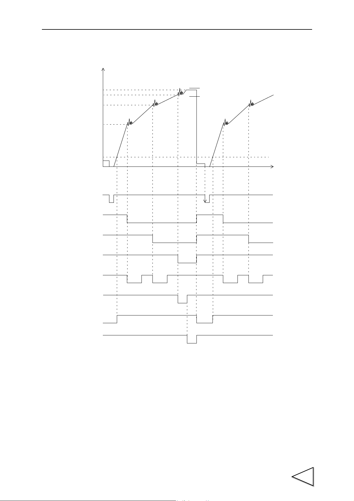
6.DISCHARGING CONTROL MODE
0
NET
Over
Under
TIME
Judgment
(Go, Over or Under)
Near Zero
Final – SP1
Final – SP2
Final – CPS
Final
Tare subtraction
SP2
SP1
SP3
Comparison
Judging Timer
Inhibit Timer
Near Zero
71

6.DISCHARGING CONTROL MODE
F701-C
6-1-2. Discharging Weighing
First supply raw material into a metering tank (hopper), then controls a weight while discharging
raw material from the metering tank.
Example of discharging weighing
In discharging weighing, the amount of discharge can be weighed by adding negative weighed
values. In this example system, raw materials are to be fed from the material tank to the weighing
tank, and a fixed quantity of raw materials are to be discharged from the weighing tank to a
container. At first, the discharge valves of the weighing tank are to be fully opened to discharge raw
materials, and the discharge valves are to be closed in the order of Set Point 1 → Set Point 2, and
Set Point 2 → Set Point 3 at the time of Final - Set Point 1, and Final - Set Point 2, respectively. The
discharge valves are to be completely closed at the time of Final - Compensation, when one
measurement is completed. When the weighing tank runs short, the feeding valves are to be opened
to replenish the weighing tank with raw materials from the material tank to weigh.
72
6.DISCHARGING CONTROL MODE
TARE
The feeding valves and discharge valves should be opened and closed through
the sequencer or relay sequence according to the control signals from the
F701-C.
(1) The valves of the material tank are opened by the lower limit signal, and raw materials are
fed into the weighing tank.
(2) It is detected by the upper limit signal that the weighing tank is full, and the valves of the mate-
rial tank are closed.
(3) By setting external input Tare subtraction ON (or with the key on the panel), Net
weight is zeroed. (Tare subtraction)
(4) The discharge valves are fully opened to start discharging. When the weighed value reaches
(Final - Set Point 1), Set Point 1 output signal turns ON. (If the comparison inhibit timer is set,
the timer starts.) The discharge valve (Set Point 1) is closed.
(5) When the weighed value reaches (Final - Set Point 2), Set Point 2 output signal turns ON. (If the
comparison inhibit timer is set, the timer starts.) The discharge valve (Set Point 2) is closed.
(6) When the weighed value reaches (Final - Compensation), Set Point 3 output signal turns ON,
and if the judging timer is set, the timer starts. The discharge valves are completely closed.
(7) After the judging timer expires, Over/Under judgment is made. If the weighed value exceeds the
range of the Over/Under setting value, the over signal or under signal is output. In weighing
from the second time onward, (3) ~ (6) are repeated in a like manner.
(8) When the weighing tank runs short of raw materials, the valves of the material tank are opened
by the output of the lower limit signal to feed raw materials into the weighing tank.
73

6.DISCHARGING CONTROL MODE
0
NET
GROSS
TIME
The Near Zero signal is used for discharge completion confirmation as in the
case of feeding weighing.
Judgment
(Go, Over or Under)
Final – CPS
Lower Limit
Final – SP2
Final – SP1
Raw materials are fed until
Gross for Upper/Lower limit comparison,
and Net for Final, Set Point 2, and Near Zero comparisons.
(In discharging weighing,
Net is compared negatively.)
the upper limit signal is output.
Tare subtraction
SP2
SP1
SP3
Comparison
Judging Timer
Lower Limit
Inhibit Timer
74
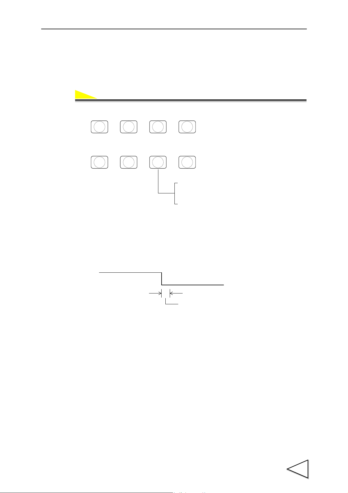
6.DISCHARGING CONTROL MODE
Operation
→→→
F
CNG/ENT CNG/ENT
2
LOWER
Discharging control mode
2 : External selection
1 : Discharging control
0 : Feeding control
→→→
1
UPPER
CNG/ENT CNG/ENT
OFF
ON
Undecided interval (within 50ms)
Discharging control
Feeding control
6-1-3. Discharging Mode
Set the feeding or discharging. Selectable methods are feeding control, discharging control and
external selection (Changing the feed/Discharge by the signal from control connector).
1) Select setting mode 2.
2) Select Discharging control mode. (1-Weighing Function 1)
- Discharging control mode by external signal
Switch with the pin set at “Feed/Discharge” out of B2 to B5 pin on the control connector.
OFF → Feeding control, ON → Discharging control.
75

6.DISCHARGING CONTROL MODE
Near Zero
Final – SP1
Final – SP2
Final – CPS
Final
0
NET
Over
Under
TIME
Near Zero
Stab le
Complete
Complete Timer
OFF
ON
ON
ON
ON
ON
OFF
Over
Go
Under
ON
t3
t2
t1t1
ON
SP2
SP1
SP3
Comparison
Judging Timer
Inhibit Timer
6-2. Simple Comparison Control and Sequence Control
6-2-1. Simple Comparison
Compares weight value with discharging value regulerly.
Output is always ON when the weight value satisfies the conditions of final discharging setting
items.
In simple comparison control, the next weighing is judged to be possible when the weight falls
short of 25% of the Final after completion of the previous weighing.
76

6.DISCHARGING CONTROL MODE
● The Over/Under comparison timing depends on the Over/Under comparison mode setting
(Weighing Function 2 in setting mode 2).
(It is set at “Regularly” in the illustration.)
● The completion signal output timing depends on the complete signal output mode setting
(Weighing Function 2 in setting mode 2).
● t1 : Comparison Inhibit Time Comparison Inhibit Time in setting mode 1
t2 : Judging Time Judging Time in setting mode 1
t3 : Complete Output Time Complete Output Time in setting mode 1
● Conditional expression
- Near Zero turns ON when Weight value ≦ Set value of Near Zero
- SP1 output turns ON when Weight value ≧ Final - SP1
- SP2 output turns ON when Weight value ≧ Final - SP2
- SP3 output turns ON when Weight value ≧ Final - CPS
- Under turns ON when Weight value < Final - Under
- Over turns ON when Weight value > Final + Over
- Go turns ON when Final + Over ≧ Weight value ≧ Final - Under
● Select the weight value for Near Zero comparison from Gross weight/Net weight (Weighing
Function 1 in setting mode 2).
● Select the comparison weight value for Set Point 1, Set Point 2 and Set Point 3 output signals,
and Over, Go and Under judgment signals from Gross weight/Net weight (Weighing Function 1
in setting mode 2).
6-2-2. Sequential Control
This is a control method which compares the weight value with discharging value after starting
signal of weighing ON.
When the starting signal ON, output of each signal of Set Point 1, Set Point 2, and Final turns ON
then the signal turns OFF after weight value satisfied the each condition.
Sequential control can be conducted without connecting external sequencer in sequence control.
Sequence controls are classified into following categories.
1) Normal sequence control
Start weighing with start signal and finish the weighing by the output of complete signal.
2) Sequence control with adjust feeding
Adjust feeding is executed for the set period in adjusting time after completing the weighing.
77
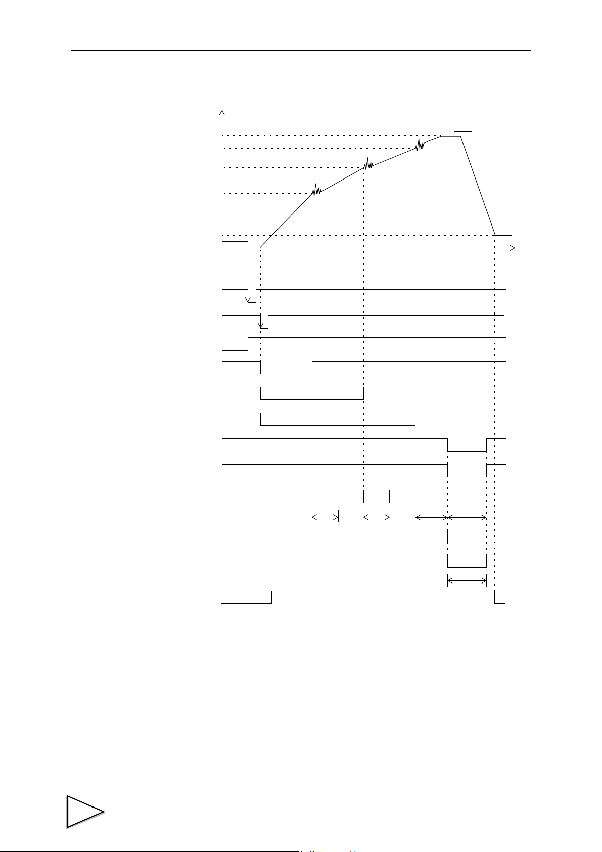
6.DISCHARGING CONTROL MODE
0
NET
Over
Under
TIME
Start
Stop
Complete
Judgment (Over, Go or Under)
ON
ON
OFF
Complete Timer
t3
ON
ON
ON
ON
t2t1t1
HOLD
Near Zero
Final – SP1
Final – SP2
Final – CPS
Final
SP2
SP1
SP3
Judging Timer
Near Zero
Tare Subtraction
Comparison
Inhibiti Timer
① Normal sequence control (with Over/Under judgment)
● The completion signal output timing depends on the complete signal output mode setting
(Weighing Function 2 in setting mode 2).
● The Over/Under comparison timing is such that the Over/Under comparison mode setting
(Weighing Function 2 in setting mode 2) is ignored, but comparisons are made when the
completion output is ON, and the weight value is held.
78
● Upper/Lower limit comparison is always made in defiance of the setting of Upper/Lower limit
comparison mode (Weighing Function 2 in setting mode 2).

6.DISCHARGING CONTROL MODE
START
STOP
ON
OFF
ON
ON
ON
ON
t3t1t1
SP1
SP2
SP3
Complete
Completion Timer
Comparison Inhibit Timer
● t1 : Comparison Inhibit Time Comparison Inhibit Time in setting mode 1
t2 : Judging Time Judging Time in setting mode 1
t3 : Complete Output Time Complete Output Time in setting mode 1
● Conditional expression
- Near Zero turns ON when Weight value ≦ Set value of Near Zero
* Set Point 1 / Set Point 2 / Set Point 3 feeding gate signal is turned ON at the ON edge (OFF
→ ON) of the start signal.
- SP1 turns OFF when Weight value ≧ Final - SP1
- SP2 turns OFF when Weight value ≧ Final - SP2
- SP3 turns OFF when Weight value ≧ Final - CPS
- Under turns ON when Weight value < Final - Under
- Over turns ON when Weight value > Final + Over
- Go turns ON when Final + Over ≧ Weight value ≧ Final - Under
● Select the weight value for Near Zero comparison from Gross weight/Net weight (Weighing
Function 1 in setting mode 2).
● Select the comparison weight value for Set Point 1, Set Point 2 and Set Point 3 output signals,
and Over, Go and Under judgment signals from Gross weight/Net weight (Weighing Function 1
in setting mode 2).
② Normal sequence control (without Over/Under judgment)
● When the setting of Judging Times in setting mode 1 is 00, Over/Under judgment is not made.
79

6.DISCHARGING CONTROL MODE
ON
ON
ON
ON
ON
HOLD
OFF
t2 t3t4
t1t1
t2
START
STOP
SP1
SP2
SP3
Complete
Judgment (Over or Go)
Judging Timer
Completion Timer
Comparison Inhibit Timer
Adjust Feeding Timer
● The completion signal output timing is such that the complete signal output mode setting
(Weighing Function 2 in setting mode 2) is ignored, but it is output at the OFF edge (ON →
OFF) of the final signal (Set Point 3 signal).
● t1 : Comparison Inhibit Time Comparison Inhibit Time in setting mode 1
t3 : Complete Output Time Complete Output Time in setting mode 1
③ Sequence with adjust feeding
80
● Set adjust feeding (ON/OFF) (Sequence Mode in setting mode 2) to ON.
● The completion signal output timing depends on the complete signal output mode setting
(Weighing Function 2 in setting mode 2).
● The Over/Under comparison timing is such that the Over/Under comparison mode setting
(Weighing Function 2 in setting mode 2) is ignored, but comparisons are made when the
completion output is ON, and the weight value is held.
● Upper/Lower limit comparison is always made in defiance of the setting of Upper/Lower limit
comparison mode (Weighing Function 2 in setting mode 2).

6.DISCHARGING CONTROL MODE
START
STOP
SP1
Sequence error
SP2
SP3
ON
OFF
ON
ON
ON
ON
ON
OFF
ONON
OFF
OFF
START
STOP
SP1
Sequence error
SP2
SP3
● t1 : Comparison Inhibit Time Comparison Inhibit Time in setting mode 1
t2 : Judging Time Judging Time in setting mode 1
t3 : Completion output time Completion Output Time in setting mode 1
t4 : Adjust Feeding Time Adjust Feeding Time in setting mode 1
About the stop signal
● When the stop signal turns ON during weight cycle, a sequence error ( ) will result and
all the signals of Set Point 1 output, Set Point 2 output and Set Point 3 output are turned OFF.
● If the start signal is turned ON when the stop signal is ON, it will become a sequence error
( ) and will not start the weighing.
81

6.DISCHARGING CONTROL MODE
Operation
ON
ON
OFF
OFF
OFF
OFF
*
START
STOP
SP1
Sequence error
SP2
SP3
→→→
F
CNG/ENT CNG/ENT
2
LOWER
1 : Sequence mode
0 : Simple comparison mode
→→→
4
SP1
CNG/ENT CNG/ENT
● For resetting the sequence error ( * ), input the ON edge (OFF → ON) of the stop signal.
The start signal is not received at the time of a sequence error.
6-2-3. Sequence Mode
Setting Simple comparison/Sequence control.
1) Select setting mode 2.
2) Select from Simple comparison mode/Sequence mode. (4-Sequence Mode)
82

6-3. Auto Free Fall Compensation Regulation /
(D1+ D2+ D3・・・・・・DA)
A
× C
Value added to Compensation value
The auto free fall compensation function stores compensation samples by
using the Over/Under judgment signals.
If the number of Judging Times is set to 00 (no judgment), the F701-C cannot
store such samples for auto free fall compensation, so that the compensation
function does not work.
For using the auto free fall compensation function, set the number of Judging
Times to 01 or more.
For details, please refer to "a) Judging Times" on P.96.
Request
Auto Free Fall Compensation ON/OFF /
Average Count of Auto Free Fall Compensation /
Auto Free Fall Compensation Coefficient
Auto free fall compensation adjusts the amount of suspended ingredient automatically to reduce
weight error. Register auto free fall compensation parameter.
Principle of auto free fall compensation
Sampling the weight value when the complete signal turns ON after Set Point 3 finished.
Record “n” times(A) the difference(D) between set Final value and actual weight value, average the
difference and multiplied by compensation coefficient, then add the result of Compensation value.
6.DISCHARGING CONTROL MODE
F701-C can regulate the value of D for minimizing the errors.
When D is within the range of (Final + AFFC.) ≧ Actual weight ≧ (Final - AFFC.), F701-C
processes auto free fall compensation.
And when compensation feeding is ON in Sequence Mode, F701-C samples the weight value
before compensation feeding.
83

6.DISCHARGING CONTROL MODE
Times Actual
Weighing
Error Average count of
AFFC.
CPS
When negative CPS
is inhibit.
When negative CPS
is effect.
00
← Power ON
1 20.050 +0.050 1 0.500 -0.033
2 20.040 +0.040 2 0.500 -0.033
3 20.070 +0.070 3 0.500 -0.033
4 20.080 +0.080
4 → 0
0.500 -0.033
+0.240/4 = 0.060
0.060×2/4 = 0.030
→ CPS Value
5 20.020 +0.020 1 0.530 -0.003
6 20.000 0.000 2 0.530 -0.003
7 20.010 +0.010 3 0.530 -0.003
8 20.110 (+0.110)
← ×3
0.530 -0.003
9 20.010 +0.010
4 → 0
0.530 -0.003
+0.040/4 = 0.010
0.010×2/4 = 0.005
→ CPS Value
10 19.880 (-0.120)
← ×1
0.535 0.002
11 19.990 -0.010 1 0.535 0.002
12 20.010 +0.010 2 0.535 0.002
13 20.000 0.000 3 0.535 0.002
14 19.980 -0.020
4 → 0
0.535 0.002
-0.020/4 = -0.005
-0.005×2/4 = -0.003
→ CPS Value
0.532 -0.001
Setting compensation coefficient
Compensation coefficient can be selected from 1/4, 2/4, 3/4, or 1.
You can get more accurate compensation value by selecting 1 when each
weight value is approximate same in each measuring or by selecting 1/4 ~ 2/4
when each weight value fluctuates in each measuring.
Example) Final 20.000
AFFC. 0.100
Average count of AFFC. 4
AFFC. coefficient 2/4
84
* When Compensation value is changed, average count of AFFC. becomes 0.

6.DISCHARGING CONTROL MODE
Operation
→→→
F
CNG/ENT CNG/ENT
1
UPPER
→→ →
Auto Free Fall Compensation Regulation
(0 ~ 99999)
7
OVER
CNG/ENT CNG/ENT
→→→
F
CNG/ENT CNG/ENT
2
LOWER
3 : AFFC. coefficient 1/4
2 : 〃 2/4
1 : 〃 3/4
0 : 〃 1
Average count of AFFC.
(1 ~ 9)
→→ →
CNG/ENT CNG/ENT
3
NEAR Z
.
2 : AFFC. ON
(Communication OP invalid)
1 : 〃 ON
0 : 〃 OFF
ZERO
Setting compensation parameter
a) AFFC. Set the regulated value to avoid the compensation value
becomes extremely large (or small).
(Input range / 0 ~ 99999)
b) AFFC. ON/OFF Selection of AFFC.
When CC-Link is installed, writing of free fall compensation
data can be prohibited, at the time of writing in the exclusive
data area.
(Select from OFF, ON, ON
(Communication OP invalid))
c) Average count of AFFC. Number of weighing value for calculating the average of
compensation.
(Input range / 1 ~ 9)
d) AFFC. coefficient Setting for avoiding fluctuations of the compensation value be
computed by multiplying the compensation and the coefficient
of not more than 1.
(Select from 1, 3/4, 2/4 or 1/4)
a)
1) Select setting mode 1.
2) Input the AFFC.. (7-Auto Free Fall Compensation Regulation)
b), c), d)
1) Select setting mode 2.
2) Set AFFC. ON/OFF, average count of AFFC. and AFFC. coefficient.
(3-Weighing Function 3)
85

6.DISCHARGING CONTROL MODE
0
WEIGHT
Over
Under
TIME
OFF
ON
ON
ON
ON
OFF
ON
Near Zero
Final – SP1
Final – SP2
Final – CPS
Final
Near Zero
Over
Go
Under
SP2
SP1
SP3
6-4. Final / Set Point 2 / Set Point 1 / Compensation / Over / Under
Setting for controlling and judging the discharge.
Outputting the control signal to external part from the control connector by the value set here.
Setting Discharging Fixed Value
Setting Display Judging Formula
Near Zero NZ
Set Point 1 SP1
Set Point 2 SP2
Set Point 3 SP3
Under
Over
Go
Weight value ≦ Set value of Near Zero
Weight value ≧ Final - SP1
Weight value ≧ Final - SP2
Weight value ≧ Final - CPS
Weight value < Final - Under
Weight value > Final + Over
Final + Over ≧ Weight value ≧ Final - Under
86

6.DISCHARGING CONTROL MODE
Operation
→→→
F
CNG/ENT CNG/ENT
0
→→ →
Final
(0 ~ 99999)
9
FINAL
CNG/ENT CNG/ENT
→→→
F
CNG/ENT CNG/ENT
0
→→ →
Set Point 2
(0 ~ 99999)
CNG/ENT CNG/ENT
5
SP2
a) Final (Input range / 0 ~ 99999)
b) Set Point 2 (Input range / 0 ~ 99999)
c) Set Point 1 (Input range / 0 ~ 99999)
d) Compensation (Input range / 0 ~ 9999: When negative compensation is inhibit)
(Input range / -9999 ~ 9999: When negative compensation is effect)
e) Over (Input range / 0 ~ 999)
f) Under (Input range / 0 ~ 999)
* Not for using Set Point 1 and Set Point 2, make the settings of Set Point 1 and Set Point 2 equal
to the Final.
a)
1) Select setting mode 0.
2) Input the Final. (9-Final)
b)
1) Select setting mode 0.
2) Input the Set Point 2. (5-Set Point 2)
87

6.DISCHARGING CONTROL MODE
→→→
F
CNG/ENT CNG/ENT
0
→→ →
Set Point 1
(0 ~ 99999)
CNG/ENT CNG/ENT
4
SP1
→→→
F
CNG/ENT CNG/ENT
0
→→ →
Compensation
(-9999 ~ 9999)
6
CPS
CNG/ENT CNG/ENT
→→→
F
CNG/ENT CNG/ENT
0
→→ →
Over
(0 ~ 999)
7
OVER
CNG/ENT CNG/ENT
→→→
F
CNG/ENT CNG/ENT
0
→→ →
Under
(0 ~ 999)
CNG/ENT CNG/ENT
8
UNDER
c)
1) Select setting mode 0.
2) Input the Set Point 1. (4-Set Point 1)
d)
1) Select setting mode 0.
2) Input the Compensation. (6-Compensation)
e)
1) Select setting mode 0.
2) Input the Over. (7-Over)
f)
1) Select setting mode 0.
2) Input the Under. (8-Under)
88
6-5. Negative Compensation
Operation
→→→
F
CNG/ENT CNG/ENT
2
LOWER
1 : Effect
0 : Inhibit
→→→
CNG/ENT CNG/ENT
3
NEAR Z
.
Negative Compensation
The selection whether the negative value of input range of compensation is including or not.
Select from Effect/ Inhibit.
- Inhibit ....................Not including the negative value of the input range of compensation.
(Input range is 0 ~ 9999.)
- Effect .....................Including the negative value of the input range of compensation.
(Input range is -9999 ~ 9999.)
1) Select setting mode 2.
2) Input the Negative Compensation. (3-Weighing Function 3)
6.DISCHARGING CONTROL MODE
89
 Loading...