

Page 1

F600AT
WEIGHING CONTROLLER
OPERATION MANUAL
01MAY2015REV.3.01
Page 2

INTRODUCTION
WARNING
CAUTION
Thank you very much for purchasing our Weighing Controller F600AT.
For good performance, and proper and safe use of the F600AT, be sure to read this instruction manual
and properly understand the contents of it before use. Also, carefully keep this instruction manual so
that it can be referred to at any time.
SAFETY PRECAUTIONS
BE SURE TO READ FOR SAFETY
Installation, maintenance and inspection of the F600AT should be performed by personnel having
technical knowledge of electricity.
In order to have an F600AT used safely, notes I would like you to surely follow divide into
" " and " ", and are indicated by the following documents. Notes indicated
INTRODUCTION
here are the serious contents related to safely. Please use F600AT after understanding the contents well.
WARNING
This sign forewarns the presence of hazards that could result in serious injury or
fatality when incorrectly handled.
CAUTION
This sign forewarns the presence of hazards that could result in personnel injury or
property damage when incorrectly handled.
I
Page 3

SAFETY PRECAUTIONS
This sign forewarns the presence of hazards
that could result in serious injury or fatality
when incorrectly handled.
Warning on design
Warning on installation
Warning on wiring
WARNING
● For the entire system to function safely when the F600AT becomes faulty or malfunctions,
provide a safety circuit outside the F600AT.
● Before using the F600AT as described below, make sure to consult with our sales
personnel.
- Use in environments not described in the operation manual.
- Use greatly impacting human lives and assets, such as medical devices, transport devices
entertainment devices, and safety devices.
● Do not modify the F600AT. Doing so may cause fire or electric shocks.
● Do not install in the following environments.
- Places containing corrosive gas or flammable gas.
- Where the product may be splashed with water, oil or chemicals.
● Do not connect a commercial power source directly to the signal input/output terminals.
● Be sure to ground the protective ground terminal.
● The attached AC cable is designed for domestic use in Japan, and its rating is 125V AC, 7A.
For use at voltages exceeding the rating and for overseas use, have a separate AC cable
prepared.
● Before performing the following, make sure that no power is applied.
- Attachment/detachment of connectors of options, etc.
- Wiring/connection of cables to the terminal blocks.
- Connection of the earth cable.
● For connection to the signal input/output terminals, check the signal names and pin
assignment numbers, and then carry out wiring properly.
● Be sure to use crimp contacts for connection to the terminal blocks, and do not to connect
bare wires as they are.
● Be sure to install the attached terminal block cover after wiring to the power input terminals.
Otherwise, electric shocks may result.
● Before applying power, carefully check the wiring, etc.
II
Page 4

SAFETY PRECAUTIONS
This sign forewarns the presence of hazards
that could result in serious injury or fatality
when incorrectly handled.
Warning during startup and maintenance
This sign forewarns the presence of hazards
that could result in personnel injury or property damage
when incorrectly handled.
Caution on installation
WARNING
● Use at a proper power supply voltage.
● Do not damage the power cord. Doing so may cause fire or electric shocks.
● Do not touch any terminal while applying power. Doing so may cause electric shocks or
malfunctions.
● If the cover of the main body is opened, it may cause an electric shock internally. Even if the
power is off, the internal capacitor is charged. Contact us for internal inspection or repair.
● In the case of smoke, an abnormal smell or strange sound, immediately turn off the power,
and disconnect the power cable.
● As for the batteries used in F600AT, do not at any time dismantle the batteries, change the
batteries shape by subjecting it to pressure or throw the batteries into fires as these may
cause the batteries to explode, catch fire or leak.
Type: CR2477/HFK (old type: CR2477-1HF) made by Panasonic
Voltage: 3V
Capacity: 1000mAh
CAUTION
● Use the F600AT as it is incorporated in a control panel, etc.
● Do not install in the following environments:
- Locations where temperature or humidity exceeds specifications;
- Locations subjected to drastic temperature fluctuations or icing and condensing;
- Outdoors or locations above 2,000m;
- Locations exposed to direct sunlight;
- Locations subject to dust accumulation;
- Locations with poor ventilation;
- Locations with a lot of salt and metal powder;
- Locations where the main unit is subject to direct vibration and shock.
● Take adequate shielding measures when using at the following locations.
- Near a power line.
- Where a strong electric field or magnetic field is formed.
- Where static electricity, relay noise or the like is generated.
● Install the F600AT as far away from devices generating high frequency, high voltage, large
current, surge, etc., as possible. Also, carry out wiring separately from their power lines. Do
not carry out parallel wiring and common wiring.
● Do not use it, broken down.
III
Page 5

RoHS-COMPLIANT PRODUCT
This sign forewarns the presence of hazards
that could result in personnel injury or property damage
when incorrectly handled.
Caution on wiring
Caution during startup and maintenance
Caution during transportation
Caution during disposal
CAUTION
● Tighten the screws for the signal input/output terminals at the specified torque.
If they are loose, shorts, fire or malfunctions may occur.
Tightening torque: 0.5N •m
● For sensors, external inputs/outputs, RS-232C and options, use shielded cables.
● The temporary overvoltage applied to the power should not exceed 1500V.
● For turning on/off the power, be sure to keep intervals of 5 seconds or more.
● After power-on, make sure to warm up the F600AT for at least 30 minutes or more before use.
● If the F600AT is not used by the specified method, its protective performance may be
impaired.
● Maintenance
- When performing maintenance, disconnect the power.
- Do not wipe with a wet rag, or with benzine, thinner, alcohol, etc. Doing so may cause
discoloration or deformation of the F600AT. In the case of heavy contamination, wipe off
the contamination with a cloth after dipping it into a diluted neutral detergent and wringing
it well, and then wipe with a soft, dry cloth.
● When the F600AT is shipped, spacers made of corrugated cardboard are used as
cushioning materials.
Though it is factory-designed so that shocks can sufficiently be absorbed, breakage may
result if shocks are applied when the spacers are reused for transportation. If you send the
F600AT to us for repair, etc., take adequate measures against shocks by using polyurethane
materials, etc., separately.
● If you dispose of the product, handle it as industrial waste.
● Remove the lithium batteries used in the F600AT and make sure to dispose them according
to classification of waste collection.
RoHS-COMPLIANT PRODUCT
The parts and attachments (including the instruction manual, packaging box, etc.) used for this unit are
compliant with the RoHS Directive restricting the use of hazardous substances with regard to adverse
effects on the environment and human body.
What is RoHS?
It is an abbreviation for Restriction on Hazardous Substances, which is implemented by the European
Union (EU). The Directive restricts the use of six specific substances in electric and electronic
equipment handled within EU borders. The six substances are lead, mercury, cadmium, hexavalent
chromium, PBB (polybrominated biphenyls), and PBDE (polybrominated diphenyl ethers).
IV
Page 6

CONTENTS
CONTENTS
1. OUTLINE ....................................................................................................... 1
1-1. Contents of the Package ...................................................................... 1
1-2. About Connectable Devices ................................................................. 1
1-3. Appearance Description ....................................................................... 1
1-3-1. Front Panel ................................................................................ 1
Touch panel display, Status indicator lamp, Prohibition of key operation
1-3-2. Rear Panel ................................................................................. 2
AC power source input connector, DC power source input terminal block,
Analog input/output connector, Signal input/output connector, Frame ground,
Protective ground, RS-232C connector, Option slot
2. CONNECTION .............................................................................................. 5
2-1. Analog Input/Output Terminals Connection ......................................... 5
2-2. Loadcell Connection ............................................................................ 6
6-wire connection, 4-wire connection
2-3. Connecting Loadcells In Parallel .......................................................... 7
2-4. Strain Gauge Sensor Cable Coloration ................................................ 7
2-5. Power Input Terminal Connection ........................................................ 8
2-6. Protective Ground Connection ............................................................. 8
2-7. SI/F Connection ................................................................................... 9
2-8. External I/O Connection ....................................................................... 9
2-8-1. How to assemble the connector ................................................. 9
2-8-2. External output connection ...................................................... 10
2-8-3. External input connection ......................................................... 10
2-8-4. RS-232C interface connection ................................................. 11
3. SETTING MODE CONFIGURATION .......................................................... 12
3-1. F600AT Screen Configuration ........................................................... 12
3-2. About a Setting Call ........................................................................... 13
3-3. Setting Modes Tree ............................................................................ 14
4. CALIBRATION ............................................................................................ 16
4-1. Span Calibration Procedure ............................................................... 17
4-2. Equivalent Input Calibration Procedure ............................................. 17
4-3. Calibration Setting .............................................................................. 18
4-3-1. LOCK2 (Calibration value LOCK) ............................................ 18
4-3-2. Minimum scale division (Can be omitted if there is no change) 18
4-3-3. Decimal place .......................................................................... 18
4-3-4. Zero calibration ........................................................................ 18
4-3-5. Equivalent input calibration ...................................................... 18
4-3-6. Span calibration ....................................................................... 19
4-4. Net Over/ Gross Over ........................................................................ 19
V
Page 7

CONTENTS
4-5. Unit Setting ........................................................................................ 19
4-6. Tare Subtraction ................................................................................ 19
4-7. Digital Zero ......................................................................................... 20
4-7-1. DZ regulation value .................................................................. 20
5. COMPARISON SETTING ........................................................................... 21
Comparison mode setting,
Comparison inhibiting time/ Judging time/ Completion output time,
Availability of fall compensation/ Fall compensating coefficient/
Average count of fall compensation, Discharge control mode,
Completion signal output mode, Overweight/underweight comparison mode,
HI/LO limit comparison selection,
Near zero comparison selection/ Preset near zero value,
Tare setting selection/ Preset tare value
6. HOW TO SET THE FUNCTIONS ............................................................... 26
For HI/LO limit comparison
(when “HI-LO comp” is selected by comp mode sel.) ,
For final discharge – over weight/under weight comparison
(when “DIS.-O/U” is selected by comp mode sel.) ,
For final discharge – HI/LO limit comparison
(when “DIS.-H/L” is selected by comp mode sel.)
7. OPERATION SETTING .............................................................................. 28
Digital filter,Analog filter, Motion detect period/ Motion detect range,
Display frequency, Zero tracking period/ Zero tracking range, Indicate color,
Backlight lighting time/ Backlight bright-and-dark time, Display table selection,
HI/LO limit output selection, LOCK1/LOCK2
8. GRAPH SETTING ....................................................................................... 32
Graphic mode, Trigger level, X-axis (time) end point, Y-axis (load) start point,
Y-axis (load) end point, Drawing weight selection
9. SYSTEM ..................................................................................................... 34
Initialization, Password, Language, 〔GROSS/NET〕key, 〔DZ〕key, 〔TARE〕key,
〔Cursor ON/OFF〕key, 〔START/STOP〕key, B4 terminal function selection
10. SEQUENCE SETTING ............................................................................. 36
Control mode, Adjust feeding/ Adjust feeding time,
Near zero confirmation at start time, Weight confirmation at start time,
AZ times, Judging times
11. TIMING CHART ........................................................................................ 38
11-1. Feed Weighing (In The Simple Comparison Mode) ......................... 38
11-2. Discharge Weighing (In The Simple Comparison Mode) ................. 39
VI
11-3. Sequence Control ............................................................................ 40
11-3-1. Normal sequence ................................................................... 40
11-3-2. Sequence when the adjust feeding is ON .............................. 41
11-3-3. Sequence with no judgment ................................................... 41
11-3-4. About the stop signal ............................................................. 42
11-3-5. Relationship between AZ times, judging times, and
automatic fall compensation ................................................... 42
Page 8

CONTENTS
12. EXTERNAL INPUT/OUTPUT SIGNALS ................................................... 43
External input signals, External output signal
13. AUTOMATIC PRINT ................................................................................ 45
13-1. In HI/LO Limit Comparison ............................................................... 45
13-2. In The Discharge Mode; Simple Comparison Mode ........................ 45
13-3. In The Discharge Mode; Sequence Mode ....................................... 45
14. RS-232C INTERFACE .............................................................................. 46
14-1. Communication Specifications ......................................................... 46
14-2. RS-232C Interface Setting ............................................................... 46
Communication mode, Baud rate, Character length, Parity bit, Stop bit,
Terminator, Flow control
14-3. Communication Format .................................................................... 47
14-3-1. Handshake ............................................................................. 47
14-3-2. Continuous transmission/ Transmission at print-time ............ 50
15. BCD DATA OUTPUT (OPTION) ............................................................... 51
15-1. Connector Pin Assignment .............................................................. 51
15-2. Equivalent Circuit ............................................................................. 52
15-3. Signal Input ...................................................................................... 52
15-4. Signal Output Timing ....................................................................... 53
15-5. BCD Data Output Setting ................................................................. 54
Data output rate, Output weight
15-6. Self Check ........................................................................................ 54
16. D/A CONVERTER (OPTION) ................................................................... 55
16-1. Connection of the D/A Converter Options ........................................ 56
16-2. D/A Converter Setting ...................................................................... 57
D/A output mode, Zero output, Full scale output
17. ERROR MESSAGE .................................................................................. 58
18. SELF-CHECK ........................................................................................... 60
Self-check DSP1, Self-check MEM, Self-check KEY, Self-check EXT,
Self-check DSP2, Self-check COM
19. BLOCK DIAGRAM .................................................................................... 61
20. DIMENSIONS ........................................................................................... 62
Standard equipment, When the external input/output signals is connected,
When the BCD option is equipped, When the CC-Link option is equipped,
When the DeviceNet option is equipped
20-1. Installation in a Panel ....................................................................... 64
VII
Page 9

CONTENTS
21. SETTING ITEM LIST ................................................................................ 65
22. SPECIFICATIONS .................................................................................... 70
Analog Section, Display Section, Setting section, Communication, Option,
External Input/Output, General Performance
VIII
Page 10

1. OUTLINE
DIGITAL
INDICATOR
DIGITAL
INDICATOR
DIGITAL
INDICATOR
DIGITAL
INDICATOR
DIGITAL
INDICATOR
DIGITAL
INDICATOR
DIGITAL
INDICATOR
DIGITAL
INDICATOR
DIGITAL
INDICATOR
DIGITAL
INDICATOR
DIGITAL
INDICATOR
WEIGHING
CONTROLLER
15JAN2008REV.1.00
WEIGHINGCONTROLLER
F600A
F600AT body ・・・1 operation manual ・・・1 Jumper wire ・・・2AC power cable・・・1
(Only at AC spec.)
[
External input/output connector ・・・1set
Connector : FCN-361J024-AU
Cover : FCN-360C024-B
]
Touch panel display
Status indicator lamp
1-1. Contents of the Package
The packaging box contains the following.
Be sure to check them before use.
1-2. About Connectable Devices
1.OUTLINE
1-3. Appearance Description
1-3-1. Front Panel
1
Page 11

1.OUTLINE
Weight display Graph display
AC power source
RS-232C connector
Signal input/output
Analog input/output
connector
Frame ground
Optional slot
Protective ground
connector
input terminal block
*DC spec.
Red (plus)
Black (minus)
DC power source
Notice
- Be aware that the voltage drops depending on the wire thickness and length.
- Never input an AC power source. Doing so will cause a failure.
(Designated when it is shipped)
input terminal block
■ Touch panel display
This is the touch panel display for displaying an indicated value and graph set value and for setting
various setting items of the F600AT. During measurement, a comparison display, hold display and
graph display can be selected according to the function in use.
■ Status indicator lamp
Lamp indication Status
Green lighting Steady state
Orange lighting Writing into internal NOVRAM. Do not turn off the power of the F600AT.
Yellow blink
Voltage drop of the internal memory backup battery.
Battery replacement is needed.
■ Prohibition of key operation
Setting of all the key operations or individual key operation ON/OFF is done by "SYSTEM". Please
refer to "9. SYSTEM" on page 34 for details.
1-3-2. Rear Panel
2
Page 12

■ AC power source input connector/ DC power source input terminal block
About the power cable
- The power cable attached to this product as standard equipment can be used in
the AC100V power supply in Japan. (Official ratings voltage AC125V)
Please use the power cable authorized in the country when you use this product
outside Japan.
- Our company sells following resistance pressure cable AC250V (European
standard product) separately.
Please purchase it from us when you need after confirming its plug shape/voltage.
CA325AC3P-CEE7/7-B2 : CEE7/7 Plug cable (2m)
- AC spec.
Connect with AC power source cable supplied.
AC voltage is 100V to 240V(
+10%, -15%) AC frequency is 50Hz/60Hz.
- DC spec. (Designated when it is shipped.)
1.OUTLINE
Connect DC power source. Voltage input is DC24V (
±15%).
■ Analog input/output connector
Pin No. Signal (6-wire) Signal (4-wire)
1 +SIG +SIG
2 -SIG -SIG
3 +EXC
4 +S
5 -EXC
6 -S
7 SHIELD SHIELD
Compatible connector : ETB42-07P
(Connector optional type: CN80)
+EXC
(Connect 3 to 4)
-EXC
(Connect 5 to 6)
3
Page 13

1.OUTLINE
■ Signal input/output connector
Compatible connector : FCN-361J024-AU
Connector cover: FCN-360C024-B
(Connector & cover optional type: CN50)
A1 COM B1 COM
A2 HH/SP1 B2 CODE0
A3 HI/OVER B3 CODE1
A4 GO/SP2 B4 CODE2/KEY_LOCK
A5 LO/UNDER B5 G/N
A6 LL/SP3 B6 DZ
A7 END B7 TARE ON
A8 NZ B8 TAR E O F F
A9 STAB B9 HOLD/JUDGE
A10 ERR B10 F/D
A11 SI/F B11 START
A12 SI/F B12 STOP
■ Frame ground
Please ground the frame ground terminal to prevent failures due to static electricity.
(The frame and the frame ground terminal are conducted.)
It may be better to remove depending on the environment of the installation location.
■ Protective ground
Be sure to ground the protective ground terminal to prevent electric shocks.
■ RS-232C connector
RS-232C connector to transmit/receive measurement data and status information, etc.
The compatible connector is HOSIDEN-manufactured TCP8080-015267 or equivalent.
Optionally available RS-232C cable (cross) [CA81-232X] is connectable.
■ Option slot
Any one of the following optional boards can be mounted.
- BCD data output
- D/A converter (voltage or current output)
- CC-Link interface
- DeviceNet interface
4
Page 14

2. CONNECTION
5 mm
Compatible connector : ETB42-07P
Pin No.1
Pin No.7
Loosen.
(Turn counterclockwise.)
Tighten.
(Turn clockwise.)
Pin No.1
Pin No.7
Tighten.
(Turn clockwise.)
Tighten.
(Turn clockwise.)
2-1. Analog Input/Output Terminals Connection
How to connect
1. Strip 5mm of the covering of the wire to be
connected. The size of connectable wires is from
0.21 to 3.31mm
Twist the tip to such an extent that it will not spread out.
3. Loosen the screw with a screwdriver to open the
connection hole.
A Phillips screwdriver 3 to 3.5mm #1 in shaft
diameter is recommended. (Precision screwdriver,
etc.)
2
(AWG12 to 24).
2.CONNECTION
4. Insert the wire into the connection hole so as not to
let the tip spread out.
5. Tighten the screw with the screwdriver.
0.5Nm of tightening torque is recommended.
6. Lightly pull the wire to make sure that it is securely clamped.
7. Insert the wire-connected plug into the F600AT
body, and tighten the screws (two).
5
Page 15

2.CONNECTION
+IN
-OUT
-IN
Loadcell
+EXC
+S
-S
-EXC
+SIG
-SIG
SHIELD
+OUT
3
4
6
5
1
2
7
+IN
-OUT
-IN
+EXC
+S
-S
-EXC
+SIG
-SIG
SHIELD
+OUT
1
2
3
4
6
5
7
Loadcell
These jumpers MUST be connected.
Notice
The loadcell excitation voltage of the F600AT is 10V. Heating or breakage may occur
unless the loadcells maximum excitation voltage is 10V or more.
2-2. Loadcell Connection
The voltage application of this equipment is 10V, and the maximum current is 120mA, to which up to
four 350Ωloadcells can be connected in parallel.
■ 6-wire connection
The loadcell input of the F600AT is a 6-wire (remote sense) connection. 6-wire shielded loadcell cable
should be used and kept separate from AC or other noise generating wire.
Remote sense lines are used to detect and correct variations in excitation voltage over long cable runs.
■ 4-wire connection
Connect 3 and 4, and 5 and 6 as shown below. Be sure to connect 4 and 6 on the terminal block with the
accessory jumper lines because if the four-wire type is used when 4 and 6 are open, apparent normal
operation is performed, but large errors are made in actuality.
6
Page 16

2.CONNECTION
R
R
R
R
R
R
+EXC
-SIG
+SIG
-EXC
+EXC
-SIG
-EXC
+SIG
SHIELD
+S
-S
‘n’ (number) loadcells connected in
parallel are considered one unit whose
capacity is ‘n’ x rated capacity of
loadcells (loadcells must have the same
capacity, bridge resistance, and mV/V).
The averaging resistor (R) must be in
same relative ratios with a low
temperature coefficient.
Averaging resistors are not needed if
loadcells were designed for parallel
connection.
Notice
When connecting several loadcells in parallel, loadcell capacity should be higher than
expected load to compensate for mechanical shock or eccentric loading.
R
R
2-3. Connecting Loadcells In Parallel
Some industrial applications require several loadcells connected in parallel (e.g., tank or flow scales).
A summing junction box should be used to facilitate connection and corner correction.
2-4. Strain Gauge Sensor Cable Coloration
Cable colors of sensors may differ from one manufacturer to another (it may even differ from one
model to another for some products). Refer to the sensor manual (or data sheet) and check signal names
and colors in order to connect the cables correctly.
7
Page 17

2.CONNECTION
Within 6mm
Protective ground
M4
2-5. Power Input Terminal Connection
Connect an AC input cord. The input power source is free in the range of 100 to 240V AC (-15%,
+10%). The frequency is 50/60Hz.
Make connections to the terminal block with a solderless terminal within 6mm in diameter as shown in
the illustration so as not to let the tip of the cable spread out.
1. Make sure that no power is applied.
2. Remove the screws (two), and remove the terminal block
cover.
3. Remove the two screws(“L” and “N”) at the terminal block.
4. Align the solderless terminals with the screw holes, and then
tighten the screws.
5. Install the terminal block cover, and fix it with the screws
(two).
2-6. Protective Ground Connection
The grounding terminal is for prevention of electric shocks.
2
Use an approx. 0.75mm
1. Make sure that no power is applied.
2. Remove the screws(M4) at the protective ground.
3. Align the solderless terminals(M4) with the screw holes, and
then tighten the screws.
thick wire, and be sure to ground.
WARNING
- Connect with no power applied because it may cause an electric shock.
- The attached AC cable is designed for domestic use in Japan, and its rating is 125V
AC, 7A. For use at voltages exceeding the rating and for overseas use, have a
separate AC cable prepared.
- Since the F600AT has no power switch, install a breaker.
8
- Be sure to ground the protective ground terminal to prevent electric shocks.
Do not use other screws than that attached to the main body.
Page 18

2.CONNECTION
ConverterDisplayPrinter
SI/F
A12
A11
← Inside Outside →
F600AT
Connector
Pan-head machine screw
M2×8 (short) (two)
Nut M2 (four)
Pan-head machine screw
M2×10 (long) (two)
Washer (two)
Case (two)
Screw (two)
2-7. SI/F Connection
The 2-wire serial interface has connective ability for coupling a UNIPULSE printer, external display, etc.
The interface is nonpolarized and up to three external instruments may be connected.
A two-core parallel cable or a cabtyre cable (Wire with covering thickened for construction) may be
used for connection.
When a two-core parallel cable or a cabtyre cable is used, the transmitting distance is approximately
30m. When a two-core shielded twisted pair cable is used, the transmitting distance is approximately
300m.
Do not parallel it with AC lines and high-voltage lines. It may cause of malfunction.
Please refer to "13. AUTOMATIC PRINT" on page 45 for print.
2-8. External I/O Connection
2-8-1. How to assemble the connector
1) Set the connector and screws (two) into the grooves of the case (one side).
2) Cover with the other case, and fit the cases.
3) Tighten the M2×8 pan-head machine screws (two).
Tighten the M2×10 pan-head machine screws (two).
Be aware that washers should be set to the M2×10 pan-head machine screws (two).
9
Page 19

2.CONNECTION
COM
Spark Killer
Load
F600AT Inside
Spark Killer
DC
Var isto r
Load
AC
Relay
Vext
Supply an external power source for a relay drive power source (Vext).
Output Data Tr
0OFF
1ON
- Output Transistor Status
A1
Power Supply
Power Supply
A2 ~ A10
Push
Switch
To rq u e
Switch
Relay
TTL Open Collector
(ON when IN is HI)
F600AT Inside
IN
IN
Open → OFF
Short → ON
- The external element is required to withstand Ic=10mA.
- Leakage from the external element is required to be 100μA or below.
+12V
COM
B1
B2 ~ B12
2-8-2. External output connection
The external output circuit is operated through an open collector.
The open collector output capacity is 50mA and the withstand voltage is up to 30V.
- Equivalent circuit
10
2-8-3. External input connection
A signal is inputted to the signal input circuit by short-circuiting or opening the input terminal and the
COM terminal. Short-circuiting is effected by means of a contact (such as a relay or a switch) or a
noncontact (such as a transistor or an open-collector TTL).
Page 20

2.CONNECTION
Pin No. Signal name
1
DCD
2
RXD
3
TXD
4
DTR
5
GND
6
DSR
7
RTS
8
CTS
Case
F.G.
DCD
DSR
RXD
TXD
DTR
GND
RTS
CTS
1
6
2
3
4
5
7
8
4
3
2
1
6
5
8
7
9
DTR
TXD
RXD
DCD
DSR
GND
CTS
RTS
RI
F600AT PC etc.
Cabling diagram
CA81-232X (optional)
* This connection diagram shows cabling
applicable to the case where your PC is
DTE (data terminal equipment).
For connection with DCE (data circuitterminating equipment), such as a modem
,
use straight type cabling.
* Prepare cabling after reconfirmation of the
connector shape and signal lines (pin
assignments) of the equipment you use.
2-8-4. RS-232C interface connection
This connector connects the RS-232C.
Example of cabling) The following shows an example of connection between DTE-DTE terminals.
This will require modification depending on the equipment to be connected.
For details, see the operation manual of the equipment to be connected.
11
Page 21

3.SETTING MODE CONFIGURATION
O K
ESC ESC
ESC
BACK
BACK BACK
BACK
oror
MODE
ESC
O K
Set value entry from
the ordinary display screen
[Ordinary display screen]
[Mode setting screen]
EACH CODE
Mode Keys
[Set value selection screen]
[Each code setting screen]
Each item
Setting keys
[Set value entry screen]
3. SETTING MODE CONFIGURATION
3-1. F600AT Screen Configuration
12
Page 22

3-2. About a Setting Call
Operation
Setting call
MODE
by key.
Operation setting
Can be changed
Page 1 Page 2 Page 3
Example) LOCK2 (Calibration Protection)
This call can be made by the following procedure.
1) Press the key on the ordinary display screen.
2) The mode setting screen appears. Select the mode.
3.SETTING MODE CONFIGURATION
Modes are as follows:
- EACH CODE - COMPARISON - OPERATION
- GRAPH - OPTION - SYSTEM
- CALIBRATION - SEQUENCE MODE - RS-232C
3) The setting function setting screen appears. Select the function.
13
Page 23

PAGE1
GRAPHIC MODE
(P.33)
TRIGGER LEVEL
(P.33)
X END POINT
(P.33)
Y START POINT
(P.33)
Y END POINT
(P.33)
PAGE2
DRAWING WEIGHT
(P.33)
Ordinary display screen
PAGE1
FINAL
(P.27)
SP1
(P.27)
SP2
(P.27)
CPS
(P.27)
PAGE2
AFFC
(P.27)
OVER
(P.27)
UNDER
(P.27)
PAGE1
COMP MODE SEL.
(P.21)
COMP INH. TIME
(P.21)
JUDGING TIME
(P.21)
COMPLETE OUT T.
(P.21)
AFFC
(P.22)
PAGE2
CPS. COEFFICIENT
(P.22)
AVG. CNT OF AFFC
(P.22)
DIS. CONTROL MODE
(P.24)
COMPLETE SIG. OUT (P.24)
OVER/UNDER COMP. (P.24)
PAGE1
DIGITAL FILTER
(P.28)
ANALOG FILTER
(P.28)
MD (PERIOD)
(P.28)
MD (RANGE)
(P.28)
DISPLAY FREQ.
(P.28)
PAGE2
ZT (PERIOD)
(P.29)
ZT (RANGE)
(P.29)
INDICATE COLOR
(P.29)
BACK LIGHT
(P.30)
PAGE3
HI/LO COMP. SEL
(P.25)
NEAR ZERO COMP
(P.25)
PRESET TARE WGT.1 (P.25)
NEAR ZERO
(P.25)
PRESET TARE WGT.2 (P.25)
PAGE3
DISPLAY SELECT
(P.30)
HI/LO OUT SEL
(P.31)
LOCK1
(P.31)
LOCK2
(P.31)
PAGE1
HH
(P.21)
HI
(P.21)
LO
(P.21)
LL
(P.21)
PAGE1
FINAL
(P.27)
SP1
(P.27)
SP2
(P.27)
CPS
(P.27)
PAGE2
AFFC
(P.27)
HI
(P.27)
LO
(P.27)
Mode setting screen
COMPARISON OPERATION GRAPHEACH CODE
*2
When “HI-LO COMP” is
selected by COMP MODE SEL
EACH CODE
*2
When “DIS. - O/U” is
selected by COMP MODE SEL.
EACH CODE
*2
When “DIS. - H/L” is
selected by COMP MODE SEL.
FIN
SP2
SP1
CPS
H I
L L
H H
L O
MODE
Mode Keys
FIN
SP2
SP1
CPS
Main display
item
*1
*1 The display item in the main screen changes by the "COMP MODE
SEL." of COMPARISON, and "DISPLAY SELECT" of OPERATION.
*2 The display item in the EACH CODE changes by the "COMP MODE
SEL." of COMPARISON.
3.SETTING MODE CONFIGURATION
3-3. Setting Modes Tree
14
Page 24

3.SETTING MODE CONFIGURATION
PAGE1
ZERO CAL.
(P.18)
SPAN CAL.
(P.19)
EQUIV. CAL.
(P.18)
BALANCE WGT VALUE((P.18)
MIN. SCALE DIV
(P.18)
PAGE2
NET OVER
(P.19)
GROSS OVER
(P.19)
UNIT DISPLAY
(P.19)
DECIMAL PLACE
(P.18)
DZ REGULATION VAL
(P.20)
CALIBRATION
PAGE1
SEQUENCE MODE
(P.36)
ADJUST FEEDING
(P.36)
AT START NZ CONF.
(P.36)
AT START WV CONF.
(P.37)
ADJ. FEEDING TIME
(P.36)
PAGE2
AZ TIMES
(P.37)
JUDGING TIMES
(P.37)
SEQUENCE MODE
PAGE1
INITIALIZATION
(P.34)
SELFCHECK DSP1
(P.60)
DELFCHECK MEM
(P.60)
SELFCHECK KEY
(P.60)
SELFCHECK EXT
(P.60)
PAGE2
SELFCHECK DSP2
(P.60)
SELFCHECK COM
(P.60)
PASSWORD
(P.34)
LANGUAGE
(P.34)
〔
GROSS/NET
〕 KEY
(P.34)
SYSTEM
PAGE1
COMM. MODE
(P.46)
BAUD RATE
(P.46)
LENGTH
(P.46)
PARITY BIT
(P.46)
STOP BIT
(P.47)
PAGE2
TERMINATOR
(47)
FLOW CONTROL
(P.47)
RS232C
PAGE1
D/A OUTPUT MODE
(P.57)
ZERO OUTPUT
(P.57)
FULLSCALE OUT
(P.57)
D/A OUTPUT
PAGE1
DATA UPDATE RATE
(P.54)
OUTPUT WEIGHT
(P.54)
SELFCHECK
(P.54)
BCD OUTPUT
A setting function
changes by the option.
Refer to attachment for
CC-Link and DeviceNet.
OPTION
PAGE3
[DZ] KEY
(P.34)
[TARE] KEY
(P.34)
[
CURSOR ON/OFF
] KEY
(P.34)
[
START/STOP
] KEY
(P.34)
B4 FUNC. SELECT
(P.35)
15
Page 25

4.CALIBRATION
Actual Load
Loadcell
Indicated value
F600AT
2.001mV/V - 100.0kg
Rated Output capacity
In case of the load
F600AT
Loadcell
Rated output value (mV/V) + Indicated value
A data sheet is attached to a loadcell at the time of purchase.
The data sheet provides data including:
Capacity Load (in kg, t, etc.)
Rated Output voltage (in mV/V)
non-linearity, hysteresis,input resistance,output resistance and zero balance.
Enter the capacity and the rated output value required for equivalent input
calibration into the F600AT.
4. CALIBRATION
Calibration is performed for matching the F600AT to a loadcell. The following two types of calibration
are available for the F600AT.
◇ Actual load calibration
Apply an actual load to the loadcell and enter the actual load value by the keys for calibration.
Calibration is accurately performed with reductions in errors.
◇ Equivalent input calibration
Calibration is performed without an actual load by entering the rated output value (mV/V) and the
capacity (to be indicated) of the strain-gage sensor by the keys. Calibration is easily performed when
no actual load is available.
For example, the gain is automatically determined by entering:
as indicated for a load.
16
Page 26

4-1. Span Calibration Procedure
Lock2 Release
Unit Setting
Zero Calibration
Calibration Protection
Minimum Scale Division
Span Calibration
Decimal Place
Lock2 Release
Zero Calibration
Calibration Protection
Equivalent Input Calibration
Unit Setting
Minimum Scale Division
Decimal Place
Follow the steps below to perform span calibration.
Release the calibration protection.
Set the unit of the load to be displayed.
Determine the decimal point place of the indicated value.
(Can be omitted if there is no change.)
Enter the minimum value of digital increments.
(Can be omitted if there is no change.)
Set the zero point of the loadcell in no-load condition
(with the loadcell unloaded).
Enter the span (gain) point of the loadcell with a load applied to the
loadcell.
4.CALIBRATION
4-2. Equivalent Input Calibration Procedure
Turn on the calibration protection for preventing misoperation.
Follow the steps below to perform equivalent input calibration.
Release the calibration protection.
Set the unit of the load to be displayed.
Determine the decimal point place of the indicated value.
(Can be omitted if there is no change.)
Enter the minimum value of digital increments.
(Can be omitted if there is no change.)
Set the zero point of the loadcell in no-load condition
(with the loadcell unloaded).
Register the rated output value and capacity of the loadcell.
Turn on the calibration protection for preventing misoperation.
17
Page 27

4.CALIBRATION
MODE
Twice
[OPERATION]
[LOCK2]
→
→→
MODE
[CALIBRATION]
[MIN. SCALE DIV.]
→
→
Once
→
MODE
[
CALIBRATION
]
[
DECIMAL PLACE
]
→
→
Once
→
→
Once
MODE
[CALIBRATION]
[ZERO CAL.]
→
→
Once
→
MODE
[CALIBRATION]
[EQUIV. CAL.]
→
→
Once
→
About the [BALANCE WGT VALUE] setting
For performing calibration, weight value input can be omitted by setting a weight
value to [BALANCE WGT VALUE] beforehand. [BALANCE WGT VALUE] is ganged
with the weight value inputs of [SPAN CAL.] and [EQUIV. CAL.].
4-3. Calibration Setting
4-3-1. LOCK2 (Calibration value LOCK)
Set values relating to calibration are locked so as not to be changed by misoperation.
Cancel the lock before performing calibration.
Alternatives: [OFF] [ON]
4-3-2. Minimum scale division (Can be omitted if there is no change)
Set the minimum scale division of the indicated value.
Setting range: 001 to 100
4-3-3. Decimal place
Set the decimal point place of the indicated value. Selection can be made from the following.
Alternatives: [NONE] [0.0] [0.00] [0.000]
4-3-4. Zero calibration
Set the zero point in no-load condition.
4-3-5. Equivalent input calibration
Set the rated output value and reading of the sensor.
Rated output value: 0.001 to 3.000mV/V
Rated value: 00001 to 99999
18
Page 28
4.CALIBRATION
MODE
[CALIBRATION]
[SPAN CAL.]
→
→
Once
→
MODE
Once
[
CALIBRATION
]
[
NET OVER
]
→→
→
Once
→
MODE
Once
[
CALIBRATION
]
[
GROSS OVER
]
→→
→
Once
→
MODE
Once
[
CALIBRATION
]
[
UNIT DISPLAY
]→→→
Once
→
TARE ON
* It operates it with the net weight (NET) displayed.
YES
NO
RESET
4-3-6. Span calibration
Set the actual load value under an actual load.
Setting range: 00001 to 99999 (The decimal point is selectable.)
4-4. Net Over/ Gross Over
When the net weight value or gross weight value exceeds a fixed regulation, an alarm is given by this
function.
NET OVER: 00000 to 99999
GROSS OVER: 00000 to 99999
The alarm is given when the following conditions are met.
Conditional expression Display
NET OVER
GROSS OVER
Net weight > “NET OVER” set value
Gross weight > “GROSS OVER” set value
4-5. Unit Setting
Set the unit of the load to be displayed.
The display value (calibration value) is not affected by changing the unit.
Alternatives: [NONE] [kg] [t] [g] [N] [lb]
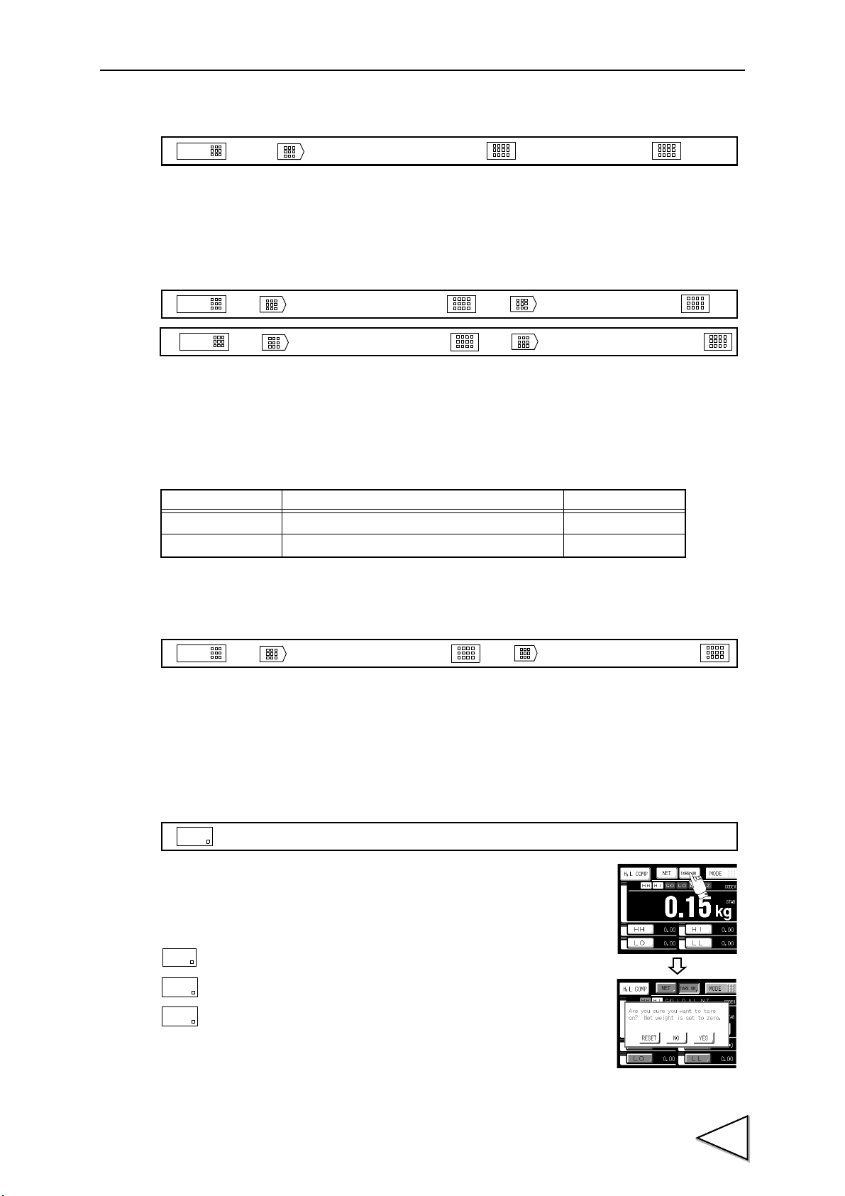
4-6. Tare Subtraction
The net weight is zeroed by this function. The gross weight value is not
changed by this operation.
NET OVER
GROSS OVER
Alternatives: [RESET] [NO] [YES]
: Perform the tare subtraction.
: Go back to the previous screen without executing tare subtraction.
: Reset the tare subtraction.
19
Page 29

4.CALIBRATION
DZ
* It operates it with the gross weight (GROSS) displayed.
YES
NO
RESET
MODE
Once
[
CALIBRATION
]
[
DZ REGULATION VAL
]
→→
→
Once
→
RESET
4-7. Digital Zero
The gross weight value is zeroed by this function.
Alternatives: [RESET] [NO] [YES]
: Perform the digital zero.
: Go back to the previous screen without executing digital zero.
: Reset the digital zero.
4-7-1. DZ regulation value
By setting the DZ regulation value, the alarm “ZALM” is displayed when operation is performed with
any gross weight value exceeding the range.
Setting range: 0000 to 9999
The displayed “ZALM” can be invalidated by the following method.
DZ reset ....................... Press the key to reset the digital zero.
DZ re-execution.......... Perform digital zero again within the regulation value range.
(Refer to "4-7. Digital Zero" on page 20.)
20
Page 30

5. COMPARISON SETTING
0
FINAL – SP1
FINAL – SP2
FINAL – CPS
Comparison inhibiting timer
Judging timer
■ Comparison mode setting
Select the comparison mode.
Alternatives: [HI - LO COMP] [DIS. - O/U] [DIS. - H/L]
Explanation of each alternative
HI/LO limit comparison (HI - LO COMP)
The net or gross weight is compared with the set values.
Final discharge – overweight/underweight comparison (DIS. - O/U)
This function is for accurate discharge of the weight value. Overweight/underweight judgment
is made by comparing with the net weight.
Final discharge – HI/LO limit comparison (DIS. - H/L)
This function is for accurate discharge of the weight value. Comparisons are made with the net weight.
High/low limit comparisons are made with the net or gross weight.
5.COMPARISON SETTING
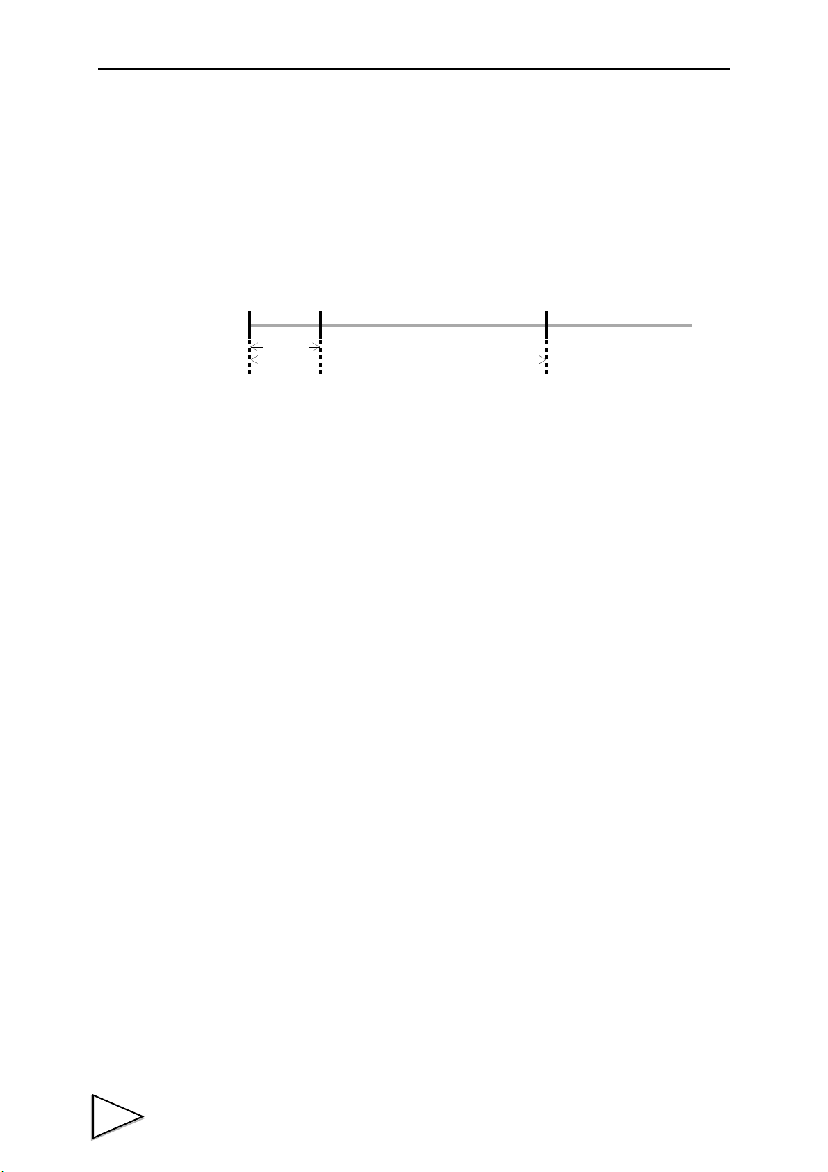
■ Comparison inhibiting time/ Judging time/ Completion output time
Valid in the discharge mode. Comparisons are not made for a fixed time by this function to prevent
inappropriate operation of control and judgment due to mechanical vibrations related to opening and
closing of valves. The length of the completion signal to be output when weighing is completed can
also be set.
COMP.INH.TIME Setting range: 0.00 to 9.99 (sec.)
JUDGING TIME Setting range: 0.00 to 9.99 (sec.)
COMPLETE OUT T. Setting range: 0.00 to 9.99 (sec.)
21
Page 31

5.COMPARISON SETTING
FINAL – SP1
FINAL – SP2
FINAL – CPS
FINAL
NET
NEAR ZERO
0
Time
STAB output
END output
Completion
ON
ON
Completionl output time setting
OVER
UNDER
output time
Value to be added to or subtracted from the preset fall value.
(D
1
+ D2+ D3・・・・・・DA)
A
× C
■ Availability of fall compensation/ Fall compensating coefficient/
Average count of fall compensation
Variations in fall, which is a major cause of errors in weighing, are automatically compensated by this
function for accurate weighing.
AFFC Alternatives: [OFF] [ON]
CPS.COEFFICIENT Alternatives: [1/1] [3/4] [2/4] [1/4]
AVG.CNT OF AFFC Setting range: 1 to 9 (times)
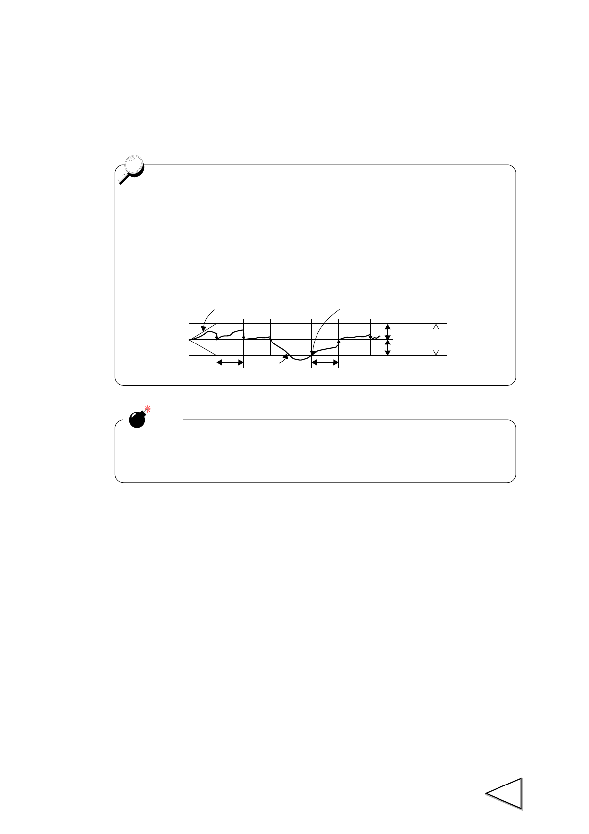
Principle of automatic fall compensation
Differences (D) between the value set at the final weight and actually weighed value are recorded by
the predetermined number of times (preset number of times) (A) to calculate a mean value, which is
multiplied by the compensating coefficient (C), and the value is added to or subtracted from the preset
fall value.
In order to minimize the errors, the values of D (D
, D2, D3, ... DA) can also be regulated.
1
Setting of automatic fall parameters
AFFC Select whether or not to use the automatic fall compensating function.
AFFC REGULATION VAL
AVG.CNT OF AFFC Set the number of times of recording the weighed value to calculate a
CPS.COEFFICIENT Set to prevent variations in compensation value through multiplication
22
Set the regulation value to prevent the compensation value from
becoming extremely large (or small). (Each code)
mean value.
by a coefficient of 1 or less.
Page 32

Example)
Times Actual Weighing Error
Average count of AFFC.
CPS
00
← Power ON
1 20.050 +0.050 1 0.500
2 20.040 +0.040 2 0.500
3 20.070 +0.070 3 0.500
4 20.080 +0.080
4 → 0
0.500
+0.240/4 = 0.060
0.060×2/4 = 0.030
→ CPS Value
5 20.020 +0.020 1 0.530
6 20.000 0.000 2 0.530
7 20.010 +0.010 3 0.530
8 20.110 (+0.110)
← ×3
0.530
9 20.010 +0.010
4 → 0
0.530
+0.040/4 = 0.010
0.010×2/4 = 0.005
→ CPS Value
10 19.880 (-0.120)
← ×1
0.535
11 19.990 -0.010 1 0.535
12 20.010 +0.010 2 0.535
13 20.000 0.000 3 0.535
14 19.980 0.020
4 → 0
0.535
-0.020/4 = -0.005
-0.005×2/4 = 0.003
→ CPS Value
0.532
Setting CPS coefficient
CPS coefficient can be selected from 1/4, 2/4, 3/4, or 1.
You can get more accurate CPS value by selecting 1 when each weight value is
approximate same in each measuring or by selecting 1/4 to 2/4 when each
weight value fluctuates in each measuring.
5.COMPARISON SETTING
Final 20.000
Auto Free Fall Compensation Regulation 0.100
Average count of AFFC. 4
CPS coefficient 2/4
23
Page 33

5.COMPARISON SETTING
OFF
FEEDING
DISCHARGE
Indeterminate interval (within 50msec.)
F/D (B10)
ON
OFF
Comparison inhibition
Comparison
Indeterminate interval (within 50msec.)
HOLD/JUDGE (B9)
ON
■ Discharge control mode
Valid in the discharge mode. Select FEEDING or DISCHARGE.
By selecting EXTERNAL, switching is carried out between FEEDING and DISCHARGE according to
the level of the input terminal “F/D.”
Alternatives: [FEEDING] [DISCHARGE] [EXTERNAL]
■ Completion signal output mode
Valid in the discharge mode. Select the method of outputting the completion signal.
Alternatives: [JUDGING TIME] [JUD. or STABLE] [JUD. & STABLE]
Explanation of each alternative
JUDGING TIME The signal is ON only for the duration of the completion output time after the
JUD. or STABLE The signal is ON only for the duration of the completion output time after the
JUD. + STABLE The signal is ON only for the duration of the completion output time after the
judging time has elapsed.
weight value has become stable or the judging time has elapsed.
weight value has become stable and the judging time has elapsed.
■ Overweight/underweight comparison mode
Valid when “DIS.-O/U” is selected by COMP MODE SEL.
Select the method of overweight/underweight comparison.
Alternatives: [REGULARLY] [COMP.SIG.] [EXT.IN] [COMP.SIG&H]
Explanation of each alternative
[REGULARLY] Comparisons are made regularly.
[COMP.SIG.] Comparisons are made when the completion signal is ON.
[EXT.IN] Comparisons are made when the external judgment input is ON.
[COMP.SIG&H] Comparisons are made when the completion signal is ON, and the weight
value is held.
*
If [EXT.IN] is selected, comparisons are made according to the level of input terminal “HOLD/JUDGE”.
* In the sequence mode (page 40), this setting is ignored, but comparisons are made when the
completion signal is ON, and the weight value is held.
24
Page 34
5.COMPARISON SETTING
■ HI/LO limit comparison selection
Valid when “HI - LO COMP” or “DIS. - H/L” is selected by COMP MODE SEL.
Select the weight value for HI-HI limit, HI limit, LO limit, and LO - LO limit comparisons.
By selecting [COMP OFF], all comparisons are turned OFF.
Alternatives: [GROSS] [NET] [COMP OFF]
■ Near zero comparison selection/ Preset near zero value
Valid in all comparison modes.
After selecting the weight value for comparisons, if the weight value ≦ preset near zero value, the
status display “NZ” lights, and the “NZ” output turns ON.
By selecting [COMP OFF], the “NZ” output is turned OFF.
NEAR ZERO COMP.: [GROSS] [NET] [COMP OFF] [ABS GROSS]
[ABS NET]
NEAR ZERO: 00000 to 99999
NEAR ZERO COMP. Operation near zero
[GROSS]
[NET]
[COMP OFF] Always OFF
[ABS GROSS]
[ABS NET]
ON when gross ≦ near zero setting
ON when net ≦ near zero setting
ON when | gross | ≦ near zero setting
ON when | net | ≦ near zero setting
■ Tare setting selection/ Preset tare value
Valid in all comparison modes.
By turning [PRESET TARE WGT.1] ON, the net changes according to the following expression:
Net = Gross - Preset tare value
(However, if tare subtraction is input, the net weight becomes 0.)
PRESET TARE WGT.1: [OFF] [ON]
PRESET TARE WGT.2: 00000 to 99999
25
Page 35
6.HOW TO SET THE FUNCTIONS
COPY
6. HOW TO SET THE FUNCTIONS
□ Code No. selection
Press the / key on the each code setting screen, and specify the code No. you want to set.
Setting range: [0 to 7] [ALL]
When each item is set with the code No. specified as “ALL,” the same set value enters into all of code
0 to 7 on the set item. This function is convenient when there is any item you want to set all code in
common.
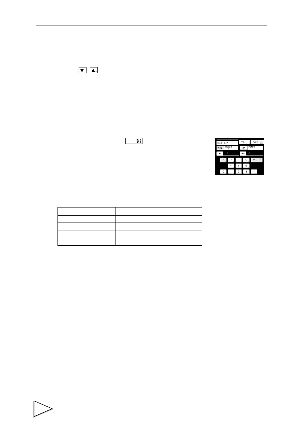
□ Code copy
Code can be copied. Press the key on the each code setting
screen. Set source and copy.
Setting range: Source: (0 to 7)
Copy: (0 to 7)
■ For HI/LO limit comparison
(when “HI-LO comp” is selected by comp mode sel.)
Setting item Input range
[HH] ±00000 to ±99999
[HI] ±00000 to ±99999
[LO] ±00000 to ±99999
[LL] ±00000 to ±99999
When the weight value > HI-HI limit, the status display “HH” lights, and the signal output “HH/SP1”
turns ON.
When the weight value > HI limit, the status display “HI” lights, and the signal output “HI/OVER”
turns ON.
When the LO limit < weight value < HI limit, the status display “GO” lights, and the signal output
“GO/SP2” turns ON.
When the weight value < LO limit, the status display “LO” lights, and the signal output “LO/
UNDER” turns ON.
When the weight value < LO-LO limit, the status display “LL” lights, and the signal output “LL/SP3”
turns ON.
*1
*1
*1
Select the weight value from net or gross.
*1: Output when the HI/LO limit comparison output is in the “NORMAL” mode.
For the “COMPARATOR” mode, refer to page 31.
26
Page 36

6.HOW TO SET THE FUNCTIONS
■ For final discharge – over weight/under weight comparison
(when “DIS.-O/U” is selected by comp mode sel.)
Setting item Input range
[FINAL] 00000 to 99999
[SP1] 00000 to 99999
[SP2] 00000 to 99999
[CPS] 0000 to 9999
[AFFC] 00000 to 99999
[OVER] 000 to 999
[UNDER] 000 to 999
When the net ≧ final weight – SP1, the status display “SP1” lights, and the signal output “HH/SP1”
turns ON.
*2
When the net ≧ final weight – SP2, the status display “SP2” lights, and the signal output “GO/SP2
turns ON.
*2
When the net ≧ final weight – CPS, the status display “SP3” lights, and the signal output “LL/SP3”
turns ON.
*2
When the net > final weight + over weight, the status display “OVER” lights, and the signal output
“HI/OVER” turns ON.
When the net < final weight – under weight, the status display “UNDER” lights, and the signal output
“LO/UNDER” turns ON.
The fall regulation value “AFFC” relates to the automatic fall compensating function.
*2: Output in the simple comparison mode. For the sequence mode, refer to
page 40.
■ For final discharge – HI/LO limit comparison
(when “DIS.-H/L” is selected by comp mode sel.)
Setting item Input range
[FINAL] 00000 to 99999
[SP1] 00000 to 99999
[SP2] 00000 to 99999
[CPS] 0000 to 9999
[AFFC] 00000 to 99999
[HI] ±00000 to ±99999
[LO] ±00000 to ±99999
When the net ≧ final weight – SP1, the status display “SP1” lights, and the signal output “HH/SP1”
turns ON.
When the net≧final weight – SP2, the status display “SP2” lights, and the signal output “GO/SP2 turns
ON.
When the net ≧ final weight – CPS, the status display “SP3” lights, and the signal output “LL/SP3”
turns ON.
When the weight value > HI limit, the signal output “HI/OVER” turns ON.
When the weight value < LO limit, the signal output “LO/UNDER” turns ON.
27
Page 37

7.OPERATION SETTING
Weight
100mSec
10ms
D
value
7. OPERATION SETTING
■ Digital filter
The A/D-converted data is moved and averaged to suppress the instability of the indicated value by this
characteristic. The number of moving averages is selectable in the range of 0 - 256. With an increasing
number, the instability of the indicated value can be suppressed, but the response to input deteriorates.
Alternatives: [OFF] [2 times] [4 times] [8 times] [16 times] [32 times] [64 times]
[128 times] [256 times]
■ Analog filter
The input signal from the strain gauge sensor is filtered to cancel unnecessary noise components by this
low-pass filter.
The cutoff frequency is selectable in the range of 2Hz - 8Hz. With an increasing cutoff frequency, the
response accelerates, but noise components may also be displayed.
Alternatives: [2Hz] [4Hz] [6Hz] [8Hz]
■ Motion detect period/ Motion detect range
Set the parameter to detect stability.
When the width of change in weight value falls below the preset range × minimum scale division, and
the state continues for the preset time or more, the weight value is regarded as stable, and the stable
status turns ON.
MD (PERIOD): 0.0 to 9.9 (sec.)
MD(RANGE): 00 to 99 (CNT)
“D” in the right picture and the range are
compared at each time of A/D conversion, and
when the preset range × minimum scale division
is exceeded, the stable status is turned OFF.
“STAB” is displayed at the upper part of the
unit display section.
The output signal “STAB” turns ON at stable-time.
*
“D” is the difference between the present
weight value and the prior weight value 100ms.
■ Display frequency
Set the frequency of rewriting the display.
The frequency can be set in the range of 1 to 10 times/sec. The internal operation speed does not change.
Setting range: 1 to 10 (times)
28
Page 38
7.OPERATION SETTING
- Zero tracking automatically takes the zero point at the preset intervals when the
amount of movement of the zero point is less than the preset range × minimum
scale division.
- The period (tracking delay) can be set in the range of 0.1 to 9.9 sec., and the range
(tracking band) can be set in the range of 00 to 99. If the set value is 02, two scale
divisions will result. Also, if the period is set at 0.0 sec. and the range at 00, zero
tracking does not function.
Boundary of zero track
DELAY
Indicated Value
-COUNT
+
0
-
From the point when it returned within the range,
DELAY
+COUNT
BAND
counting will be resumed.
Notice
Since zero tracking should function from the zero point of gross, it does not function if
the indicated value has already exceeded the tracking band. Take the zero point again
by digital zero or zero calibration.
■ Zero tracking period/ Zero tracking range
Slow changes in zero point due to drifting are automatically tracked and compensated by this function.
ZT (PERIOD): 0.0 to 9.9 (sec.)
ZT (RANGE): 00 to 99 (CNT)
■ Indicate color
The indicated value display color can be changed.
By setting Comp.(Comparison Result), the indicated value display color changes following the
comparison status.
Alternatives: [Yellow] [Green] [Blue] [Comp.]
【When Comparison mode is “HI-LO COMP”】
OK Green
HI, LO Yellow
HH, LL Red
【When Comparison mode is “DIS.-O/U”】
Normal Blue
OVER, UNDER Red
【When Comparison mode is “DIS.-H/L”】
Normal Blue
HI, LO Red
29
Page 39
7.OPERATION SETTING
Bright Dark
10 min.
60 min.
Light Out
■ Backlight lighting time/ Backlight bright-and-dark time
This function changes the brightness of the backlight when touch screen has not been used for
certain period of time.
The ON time ( lighting time of the backlight) and the Low time ( bright→dark switching time of the
backlight) are set up.
When you use it in the state which a display is always in sight, set the ON time to 0 minutes.
When you want the backlight always bright, set 0 minutes for both the ON time and the Low time.
The backlight is turned bright by touching the panel when the backlight is turned off or it is dark.
Ex.) Set 60 minutes to ON time, 10 minutes to Low time.)
Setting range: 0 to 99 (min.) (with both time)
■ Display table selection
Select the display of set values at the bottom of the weight display screen from three combinations.
The combinations vary with comparison modes.
Alternatives: [F, SP1-3] [F, SP 3, H, L] [F, S P 3 , T, Z]
(* When “DIS.-H/L” is selected)
Explanation of combination in each comparison mode
【For HI/LO limit comparison (when “HI-LO COMP” is selected)】
- HH, H, L, LL (HI-HI limit, HI limit, LO limit, LO-LO limit)
- H, L, T, Z (HI limit, LO limit, Preset TARE, NEAR ZERO)
- HH, LL, T, Z (HI-HI limit, LO-LO limit, Preset TARE, NEAR ZERO)
【For final discharge – overweight/underweight comparison (when “DIS.-O/U” is selected)】
- F, SP1-3 (FINAL weight, SP1, SP2, SPS)
- F, SP3, O, U (FINAL weight, SPS, Overweight, Under weight)
- F, SP3, T, Z (FINAL weight, SPS, Preset TARE, NEAR ZERO)
【For final discharge – high/low limit comparison (when “DIS.-H/L” is selected)】
- F, SP1-3 (FINAL weight, SP1, SP2, SPS)
- F, SP3, H, L (FINAL weight, SPS, HI limit, LO limit)
- F, SP3, T, Z (FINAL weight, SPS, Preset TARE, NEAR ZERO)
30
Abbreviations
HH..... HI-HI limit H.........HI limit L .........LO limit LL ........LO-LO limit
T ........ Preset TARE Z ......... NEAR ZERO O.........Over weight U ..........Under weight
F
........ FINAL weight
SP1 ..... SP1 SP2 .....SP2 SP3.......SPS
Page 40
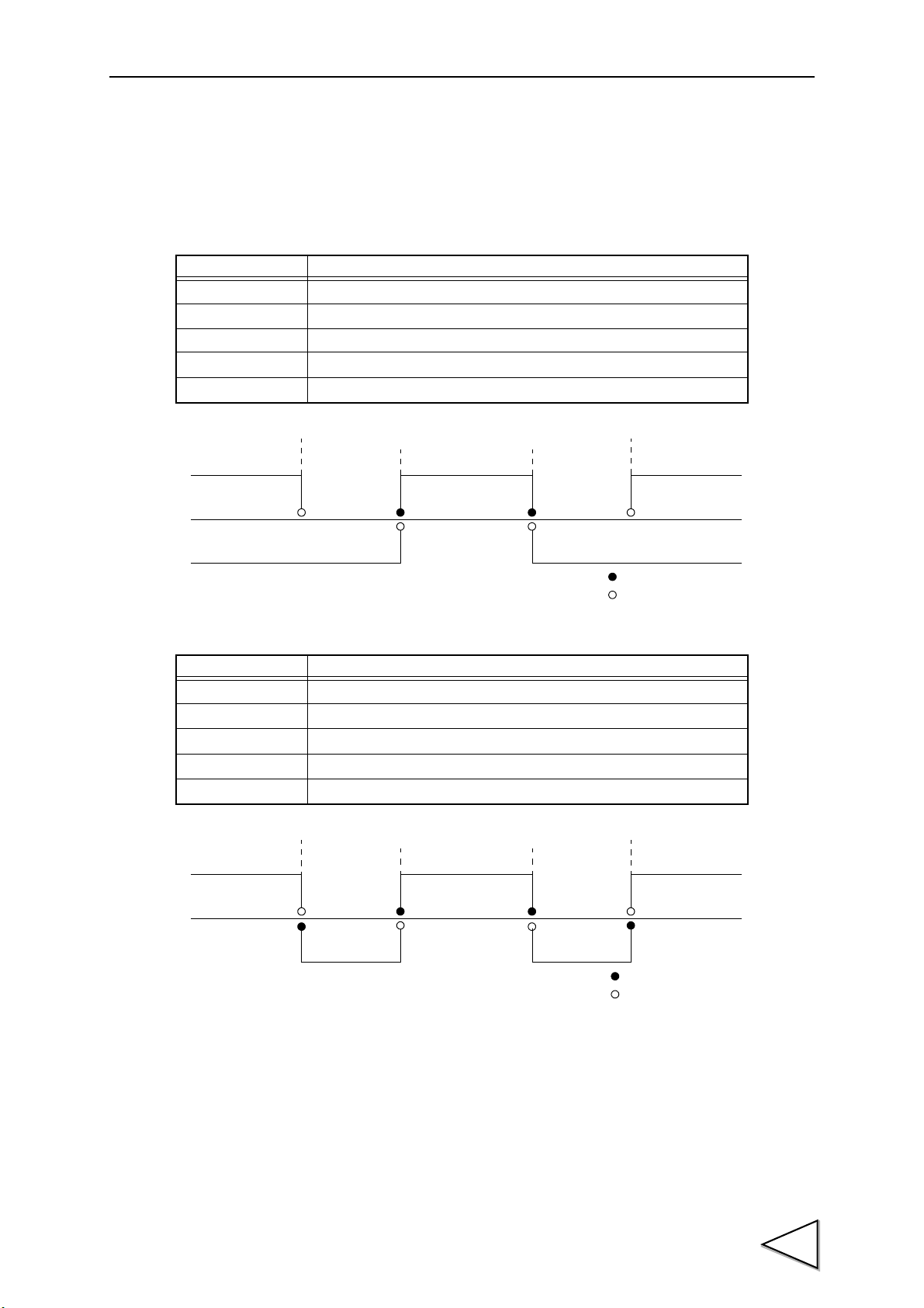
■ HI/LO limit output selection
Preset lo-lo limit Preset hi-hi limit
Preset low limit Preset high limit
LL GO HH
LO HI
……This value is included.
……This value is not included.
Preset LO-LO limit Preset HI-HI limit
Preset LO limit Preset HI limit
LL GO HH
LO HI
……This value is included.
……This value is not included.
Select the method of comparison output in the HI/LO limit comparison mode.
Alternatives: [NORMAL] [COMPARATOR]
□ Explanation of each alternative
[NORMAL]
Signal name Condition
HH
HI
GO ON when HH, HI, LO and LL are all OFF
LO
LL
ON when the preset HI-HI limit < weight value
ON when the preset high limit < weight value
ON when the weight value < preset low limit
ON when the weight value < preset LO-LO limit
7.OPERATION SETTING
[COMPARATOR]
Signal name Condition
HH
HI
GO
LO
LL
ON when the preset HI-HI limit < weight value
ON when the preset HI limit < weight value ≦ preset HI-HI limit
ON when the preset LO limit ≦ weight value ≦ preset HI limit
ON when the preset LO-LO limit ≦ weight value < preset LO limit
ON when the weight value < preset LO-LO limit
■ LOCK1/LOCK2
This function protects set values and calibration from being changed by mistake.
LOCK1: [OFF] [ON]
LOCK2: [OFF] [ON]
* Please refer to "21. SETTING ITEM LIST" on page 65 for the setting that LOCK is done by
LOCK1 and LOCK2.
31
Page 41

8.GRAPH SETTING
X-axis (time axis)
Graphic display START/STOP
Indicated value display (At cursor ON time, the cursor point value is displayed.)
Y-axis (load axis)
Cursor ON/OFF key
When the cursor display is on and when the setting screen is open, the graph is
not upgraded.
The cursor moves to the directly-pressed
Cursor move buttons (The cursor moves on the X-axis.)
Cursor ON/OFF key
place on the graph.
Drawing area100
Y
X
200
X-axis end point
Y-axi s
Y-axi s
0
end point
start point
8. GRAPH SETTING
□ Graphic display screen
Graph is updated while operating on the ordinary display screen (a comparison, a hold, graph).
□ Cursor display screen
□ X-axis
“X-axis” is time axis setting. One screen is drawn between the instant of inputting the start and the
instant of the time set by the X-axis end point.
The number of drawing points is 200, and drawing is performed with the representative value at each of
the set time divided by the number of drawing points.
□ Y-axis
“Y-axis” is load axis setting. Drawing is performed from the value set by the Y-axis start point to the
value set by the Y-axis end point. (The number of drawing points is 100.)
32
Page 42

8.GRAPH SETTING
START
STOP
START
START
In drawing in the discharge mode, an “×” mark is drawn when the net weight
exceeds the following:
[Final weight – SP1] [Final weight – SP2] [Final weight - CPS]
■ Graphic mode
Select the method of drawing.
Alternatives: [CONTINUITY] [SINGLE] [LEVEL]
□ Explanation of each alternative
[
CONTINUITY
[SINGLE] Drawing is started by the key, and only one screen is drawn.
[LEVEL] Drawing is started when the drawing weight exceeds the trigger level, or the
]Drawing is started by the key, and drawing is repeated until the
key is input.
key, and only one screen is drawn.
■ Trigger level
Set the graph drawing start level (trigger level) if [LEVEL] has been selected by graphic mode
selection.
Setting range: 00000 to 99999
■ X-axis (time) end point
Set the time to display one screen.The setting range is from 2 sec. to 98 sec. (at intervals of 2 sec.)
The X-axis (time) end point can also be set from the graph screen.
Setting range: 2 to 98 (sec.)
■ Y-axis (load) start point
Set the graph drawing start point. (±00000 to ±99999)
Setting range: ±00000 to ±99999
■ Y-axis (load) end point
Set the graph drawing end point.The Y-axis (load) end point can also be set from the graph screen.
Note) The start point should be smaller than the end point.
Setting range: ±00000 to ±99999
■ Drawing weight selection
Select the weight for drawing.
Alternatives: [GROSS] [NET]
33
Page 43

9.SYSTEM
GROSS
NET
DZ
TARE ON
CUR.ONCUR.
OFF
START
STOP
9. SYSTEM
■ Initialization
All the set values of each setting item are initialized to their factory defaults.
Select the setting item you want to initialize.
Alternatives: [CODE] [COMP.] [OPR.] [CAL.] [etc.]
* If LOCK1/LOCK2 of setting item which you intend to initialize is ON, the initialization cannot be
executed.
■ Password
This setting is for maintenance and inspection. Do not operate.
■ Language
The display language is selectable between Japanese and English.
JPN: JAPANESE
ENG: ENGLISH
■ 〔GROSS/NET〕key
Set OFF/ON of the key operation of / key.
Alternatives: [OFF] [ON]
■ 〔DZ〕key
Set OFF/ON of the key operation of key.
Alternatives: [OFF] [ON]
■ 〔TARE 〕key
Set OFF/ON of the key operation of key.
Alternatives: [OFF] [ON]
■ 〔Cursor ON/OFF〕key
Set OFF/ON of the key operation of / key.
Alternatives: [OFF] [ON]
■ 〔START/STOP〕key
Set OFF/ON of the key operation of / key.
Alternatives: [OFF] [ON]
34
Page 44

■ B4 terminal function selection
When KEY_LOCK terminal function is selected, measurement code that can
be specified from the outside can be specified by CODE0 terminal,CODE1
terminal.
It is limited to CODE number 0 to 3.
Selection of the KEY_LOCK terminal function from the CODE2
terminal function by the B4 Function Selection setting makes the
following effective.
KEY_LOCK: When the terminal is short-circuited,
all key operations are disabled.
9.SYSTEM
35
Page 45

10.SEQUENCE SETTING
With the near zero confirmation at start time setting “ON,” When the start signal is
input, if the near zero signal is OFF, the feeding gate signal is not turned ON, but a
sequence error results. (Sequence error 4)
10. SEQUENCE SETTING
Operation is performed by following the sequence that weighing is started by inputting the ON edge to
the start signal (external input/output connector pin B11) of the F600AT, and weighing is finished by
the completion signal.
This is valid only in the discharge mode.
Please refer to "11. TIMING CHART" on page 38 for each operation timing.
■ Control mode
Select sequence mode or simple comparison mode.
Alternatives: [SIMPLE COMP.] [SEQUENCE]
■ Adjust feeding/ Adjust feeding time
The setting is valid in the sequence mode.
ADJUST FEEDING: [OFF] [ON]
ADJ.FEEDING TIME: 0.00 to 9.99 (sec.)
What is “Adjust feeding”?
If the Net < Final weight – Under weight at the completion signal ON timing (when the judging time
has elapsed after the SP3 signal is turned OFF in the example on P.40), the completion signal is not
turned ON, but the SP3 signal is turned ON for the adjust feeding time.
Adjust feeding is valid only in the “Final discharge – Over weight/Under weight comparison mode”.)
■ Near zero confirmation at start time
The setting is valid in the sequence mode.
Alternatives: [OFF] [ON]
36
Page 46

■ Weight confirmation at start time
When the start signal is input, if
(1) the net ≧ final weight – SP1, or
(2) the final weight – CPS≦0,
the feeding gate signal (SP1, SP2, or SP3) is not turned ON, but a sequence error
results. (Sequence error 5)
((1) is applicable only when the “weight confirmation at start time” setting is ON.)
When the start signal is input, tare subtraction is performed at intervals of these
times.
When the completion signal is turned ON, Over weight/Under weight comparisons
are made at intervals of these times.
The setting is valid in the sequence mode.
Alternatives: [OFF] [ON]
■ AZ times
The setting is valid in the sequence mode.
10.SEQUENCE SETTING
Setting range: 00 to 99 times
■ Judging times
The setting is valid in the sequence mode.
Setting range: 00 to 99 times
37
Page 47

11.TIMING CHART
0
NET
Time
OFF
ON
ON
ON
ON
OFF
ON
t3
t2
t1t1
ON
t1: Comparison inhibiting time
COMP.INH.TIME under
COMPARISON
t2: Judging time
JUDGING TIME under
COMPARISON
t3: Completion output time
COMPLETE OUT T. under
COMPARISON
NEAR ZERO
FINAL – SP1
FINAL – SP2
FINAL – CPS
FINAL
NZ output
SP1 output
SP2 output
SP3 output
Comparison
Judging time
STAB output
END output
OVER output
UNDER output
inhibiting time
OVER
UNDER
11.TIMING CHART
11-1. Feed Weighing (In The Simple Comparison Mode)
38
The overweight/underweight comparison timing depends on the OVER/UNDER COMP. setting under
COMPARISON. (It is set at “REGULARLY” in the illustration.)
The END signal output timing depends on the COMPLETE SIG.OUT setting under COMPARISON.
Conditional expression
- NZ output ON when the weight value ≦ preset near zero value
SP1 output ON when the net ≧ preset final weight value – preset SP1 value
-
-
SP2 output ON when the net ≧ preset final weight value – preset SP2 value
SP3 output ON when the net ≧ preset final weight value – preset CPS value
-
- UNDER
- OVER
output ON when the net < preset final weight value – preset underweight value
output ON when the net > preset final weight value + preset overweight value
Select the weight value for near zero comparison from GROSS or NET under COMPARISON setting
menu.
Page 48

11.TIMING CHART
LO limit
NET
0
Time
t1 t1
t2 t2
t3 t3
NET
GROSS
The near zero signal is used for
discharge completion confirmation
as in the case of feed weighing.
GROSS for high/low limit comparison, and NET for final weight,
before-final-weight,and near zero comparisons.
(In discharge weighing, NET is compared negatively.)
Materials are fed until the HI limit signal is output.
FINAL – SP1
FINAL – SP2
FINAL – CPS
TARE ON input
SP2 output
SP1 output
SP3 output
Comparison
Judging time
LO limit or less
inhibiting time
NZ output
END output
OVER (UNDER)
output
t1: Comparison inhibiting time
COMP.INH.TIME under
COMPARISON
t2: Judging time
JUDGING TIME under
COMPARISON
t3: Completion output time
COMPLETE OUT T. under
COMPARISON
11-2. Discharge Weighing (In The Simple Comparison Mode)
The overweight/underweight comparison timing depends on the OVER/UNDER COMP. setting under
COMPARISON. (It is set at “COMPLETE SIGNAL ON” in the illustration.)
The completion signal output timing depends on the COMPLETE SIG. OUT setting under
COMPARISON.
Conditional expression
- NZ output ON when the weight value ≦ preset near zero value
-
SP1 output ON when the net ≧ preset final weight value – preset SP1 value
SP2 output ON when the net ≧ preset final weight value – preset SP2 value
-
-
SP3 output ON when the net ≧ preset final weight value – preset CPS value
- UNDER
- OVER
output ON when the net < preset final weight value – preset underweight value
output ON when the net > preset final weight value + preset overweight value
Select the weight value for near zero comparison from GROSS or NET under COMPARISON setting
menu.
39
Page 49

11.TIMING CHART
Comparison
inhibiting time
Judging time
NZ output
0
NET
Time
ON
ON
OFF
t3
ON
ON
ON
ON
t2
t1t1
Hold
t1: Comparison inhibiting time
COMP.INH.TIME under
COMPARISON
t2: Judging time
JUDGING TIME under
COMPARISON
t3: Completion output time
COMPLETE OUT T. under
COMPARISON
OVER
UNDER
FINAL – SP1
FINAL – SP2
FINAL – CPS
FINAL
NEAR ZERO
TARE ON input
START input
STOP input
SP1 output
SP2 output
SP3 output
END output
Completion signal
Judgment output
output time
(OVER or Proper or UNDER)
11-3. Sequence Control
11-3-1. Normal sequence
40
The completion signal output timing depends on the COMPLETE SIG.OUT setting under
COMPARISON.
The overweight/underweight comparison timing is such that the OVER/UNDER COMP. setting under
COMPARISON is ignored, but comparisons are made when the completion output is ON, and the
weight value is held.
Conditional expression
- NZ output ON when the weight value ≦ preset near zero value
* The large/medium/small feeding gate signal is turned ON at the ON edge (OFF → ON) of the START
signal.
- SP1 output OFF when the net weight ≧ preset final weight value – preset SP1 value
SP2 output OFF when the net weight ≧ preset final weight value - preset SP2 value
-
SP3 output OFF when the net weight ≧ preset final weight value – preset CPS value
-
-
UNDER output ON when the net weight < preset final weight value – preset underweight value
-
OVER output ON when the net weight > preset final weight value + preset overweight value
Select the weight value for near zero comparison from GROSS or NET by NEAR ZERO COMP. under
COMPARISON. The sequence mode is valid only in the final discharge mode.
Page 50

11-3-2. Sequence when the adjust feeding is ON
Completion output time
Adjust feeding time
Judging time
Comparison inhibiting time
Judgment output
END output
SP1 output
ON
ON
ON
ON
ON
Hold
OFF
t2 t3t4t1t1 t2
START input
STOP input
SP2 output
SP3 output
t1: Comparison inhibiting time
COMP.INH.TIME under
COMPARISON
t2: Judging time
JUDGING TIME under
COMPARISON
t3: Completion output time
COMPLETE OUT T. unde
COMPARISON
t4: Adjust feeding time
ADJ.FEEDING TIME
under SEQUENCE MODE
(OVER)
SP1 output
SP2 output
SP3 output
END output
Comparison inhibiting time
Completion output time
ON
OFF
ON
ON
ON
ON
t3t1t1
t1: Comparison inhibiting time
COMP.INH.TIME under
COMPARISON
t3: Completion output time
COMPLETE OUT T. under
COMPARISON
START input
STOP input
11.TIMING CHART
The completion signal output timing depends on the COMPLETE SIG.OUT setting under
COMPARISON.
The overweight/underweight comparison timing is such that the OVER/UNDER COMP. setting under
COMPARISON is ignored, but comparisons are made when the completion output is ON, and the
weight value is held.
11-3-3. Sequence with no judgment
When the number of JUDGING TIMES under SEQUENCE MODE is 00, overweight/underweight
judgment is not made.
The END signal output timing is such that the COMPLETE SIG.OUT setting is ignored, but it is output
at the OFF edge (ON → OFF) of the final weight signal (SP3 signal).
41
Page 51
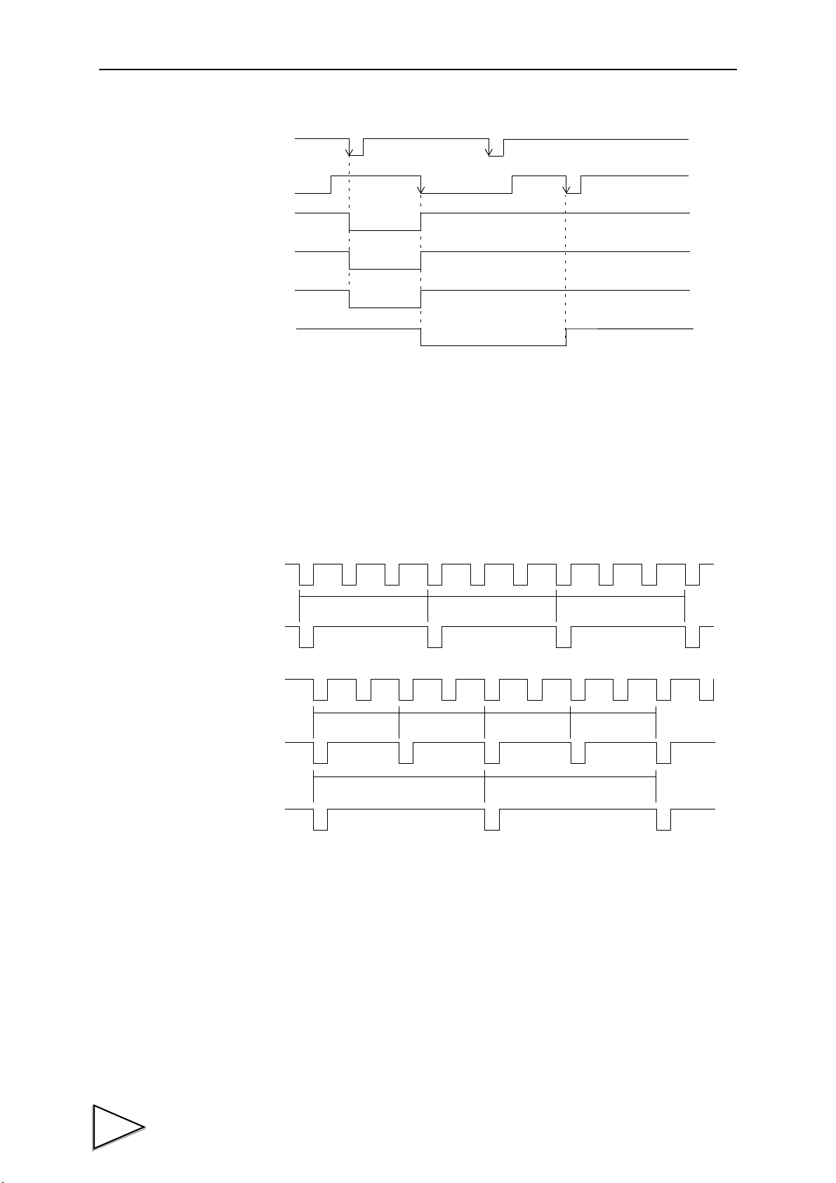
11.TIMING CHART
ON
OFF
ON
ON
ON
ON
START input
STOP input
SP1 output
SP2 output
SP3 output
ERR output
START
AZ times
3 times
TAR E O N
END
Judgment
Fall compensation
Judging times 2 times
Average count of automatic
2 times
fall compensation
11-3-4. About the stop signal
When the STOP signal is turned ON, all the signals of the SP1 output, SP2 output and SP3 output are
turned OFF.
If the START signal is turned ON when the STOP signal is ON, a sequence error will result.
For resetting the sequence error, input the stop signal again.
11-3-5. Relationship between AZ times, judging times, and
automatic fall compensation
【Example: AZ times=3, JUDGING times=2, AVG.CNT of AFFC=2】
When the number of AZ times is set at 01, tare subtraction is performed at each time when weighing is
started.
When the number of AZ times is set at 02 to 99, tare subtraction is performed at the intervals of these
times.
When the number of AZ times is set at 00, the AZ function is turned OFF.
When the number of judging times is set at 01, judgment is made at each time when weighing is
finished.
When the number of judging times is set at 02 to 99, judgment is made at the intervals of these times.
When the number of judging times is set at 00, overweight/underweight comparisons are not made.
Since weighed values for automatic fall compensation are sampled at the time of judgment, the
automatic fall compensation does not function when no judgment is made.
42
Page 52

12.EXTERNAL INPUT/OUTPUT SIGNALS
12. EXTERNAL INPUT/OUTPUT SIGNALS
■ External input signals
(1) CODE0 to CODE2 <Level input> (B2, B3, B4)
Input signals to specify codes for weighing externally.
CODE2 CODE1 CODE0 Selected CODE
Open Open Open 0
Open Open Shorted 1
Open Shorted Open 2
Open Shorted Shorted 3
Shorted Open Open 4
Shorted Open Shorted 5
Shorted Shorted Open 6
Shorted Shorted Shorted 7
* CODE2 is also usable as a Key LOCK terminal.
(Refer to " ■ B4 terminal function selection" on page 35.)
(2) G/N (GROSS/NET) switching <Edge input> (B5)
The weight value of the main unit and indicator is switched.
The ON edge (OFF → ON) of the external input will result in gross display (GROSS).
The OFF edge (ON → OFF) of the external input will result in net display (NET).
(3) D/Z (Digital zero) <Edge input> (B6)
The ON edge (OFF → ON) of the external input will zero the gross weight.
However, the range that can be zeroed is within the DZ regulation value. Out of this range, zero
will not result, but “ZALM” will light.
(4) TARE ON (Tare subtraction) <Edge input> (B7)
The ON edge (OFF → ON) of the external input will result in immediate tare subtraction to zero
the net weight.
(5) TARE OFF (Tare subtraction reset) <Edge input> (B8)
The ON edge (OFF → ON) of the external input will reset the above tare subtraction. However,
the tare setting is not cancelled.
(6) HOLD (Hold) <Level input> (B9)
As long as the external input is ON, the weight value and comparison are held.
* “HOLD” lights during holding.
* This input terminal can be set to judgment input. It cannot be used for holding in the sequence
mode and when over/under comparison is made by external judgment.
(7) JUDGE (Judgment) <Level input> (B9)
This is valid when over/under comparison is set to external judgment input. (Refer to page 24.)
* This input terminal can be set to HOLD.
43
Page 53

12.EXTERNAL INPUT/OUTPUT SIGNALS
These are valid when the control is
in the sequence mode.
(Refer to page 42.)
Pulse width:
OFF
ON
OFF
ON
Indeterminate interval
Charge control Discharge control
< Edge input > < Level input >
50m sec. or more.
(within 50m sec.)
Varies depending on the comparison mode.
(Refer to page 26.)
(8) F/D (Charge/Discharge) <Level input> (B10)
This is valid when charge/discharge selection is external.
OFF will result in charge control, and ON will result in discharge control. (Refer to page 24.)
(9) START (Start) <Edge input>
(10) STOP (Stop) <Edge input, Level input>
■ External output signal
(1) HH/SP1 (Comparison output) (A2)
(2) HI/OVER (Comparison output) (A3)
(3) GO/SP2 (Comparison output) (A4)
(4) LO/UNDER (Comparison output) (A5)
(5) LL/SP3 (Comparison output) (A6)
(6) END (Completion) (A7)
This indicates measurement completion output, which is valid only in the “carving-out” mode.
(7) NZ (Near zero) (A8)
This is near zero comparison output. (Refer to page 25.)
(8) STAB (Stable) (A9)
This turns ON when a stable. (Refer to page 28.)
(9) ERR (Weight error or sequence error) (A10)
This turns ON when a weight error or sequence error occurs.
44
Page 54

13. AUTOMATIC PRINT
The F600AT can output an automatic print command to the printer or indicator connected to the SI/F.
The automatic print output timing varies depending on the setting.
13-1. In HI/LO Limit Comparison
The command is output at the ON edge of the stable status when the near zero signal is OFF. If the
automatic print is output, it can next be output after the near zero signal is once turned ON.
13-2. In The Discharge Mode; Simple Comparison Mode
The command is output at each ON edge of the completion signal. The value of the number of judging
times is ignored.
13-3. In The Discharge Mode; Sequence Mode
13.AUTOMATIC PRINT
The command is output at the ON edge of the completion signal at the intervals of judging times. When
the number of judging times is 0, the automatic print is not output.
45
Page 55

14.RS-232C INTERFACE
14. RS-232C INTERFACE
The RS-232C is an interface to read the indicated value and status of the F600AT and to write
parameters into the F600AT.
This interface is convenient to process controls, totals, records, etc., by connecting the F600AT to a
computer, process controller, sequencer or the like.
14-1. Communication Specifications
□ Specifications
Signal level: Based on RS-232C
Transmitting distance: Approx.15m
Transmitting method: Asynchronous, Full duplex
Transmitting speed: 1200, 2400, 4800, 9600, 19200bps selectable
Bit configuration: Start bit 1bit
Character length 7 or 8 bit selectable
Stop bit 1 or 2 bit selectable
Parity None, odd or even selectable
Terminator CR, CR+LF selectable
Code: ASCII
14-2. RS-232C Interface Setting
Set the RS-232C communication conditions of the F600AT.
■ Communication mode
Alternatives: [HAND SH.] [CONTINUITY] [AT PRINT]
HAND SH.
Communications are carried out according to the commands from the host computer.
Reading of weight values, status and set values, writing of set values, and instructions of operations can
be performed.
CONTINUITY
The displayed weight value and status are transmitted continuously.
AT PRINT
The displayed weight value and status are transmitted at the print timing.
For the print timing, refer to "13 AUTOMATIC PRINT" on page 45.
■ Baud rate
Alternatives: [1200bps][2400bps][4800bps][9600bps][19200bps]
■ Character length
Alternatives: [7bit] [8bit]
■ Parity bit
Alternatives: [NONE] [ODD] [EVEN]
46
Page 56
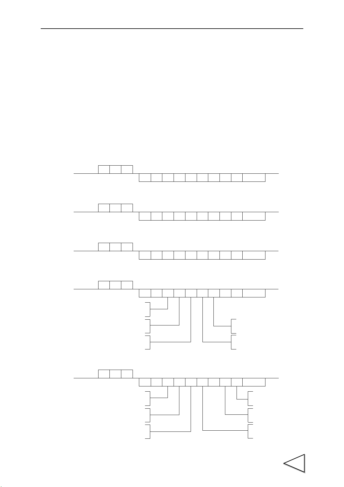
■ Stop bit
Host
F600AT
RA
RA
+
100 00.
Ter minator
CR
Host
F600AT
RB
RB
+
100 00.
Ter minator
CR
Host
F600AT
RC
RC
+
100 00.
Ter minator
CR
NET display
GROSS display
In tare subtraction
Not in tare subtraction
At hold-time
Not at hold-time
At zero-error-time
Not at zero-error-time
At stable-time
Not at stable-time
Host
F600AT
RD
RD0000 000
Ter minator
CR
: 1
: 0
: 1
: 0
: 1
: 0
: 1
: 0
: 1
: 0
Completion
Overweight
Underweight
Host
F600AT
RE
RE0000 000
Ter minator
CR
1: ON
0: OFF
1: ON
0: OFF
1: ON
0: OFF
1: ON
0: OFF
1: ON
0: OFF
1: ON
0: OFF
SP1
SP2
SP3
Alternatives: [1bit] [2bit]
■ Termi nat or
Alternatives: [CR] [CR+LF]
■ Flow control
Alternatives: [OFF] [RTS/CTS]
14-3. Communication Format
14-3-1. Handshake
- Gross read (sign, 5-digit weight, decimal place)
14.RS-232C INTERFACE
- Net read (sign, 5-digit weight, decimal place)
- Tare read (sign, 5-digit weight, decimal place)
- Status read (7-digit)
- Status read (7-digit)
47
Page 57
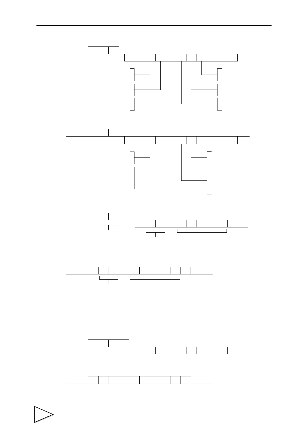
14.RS-232C INTERFACE
HI-HI limit
HI limit
Proper weight
Near zero
LO-LO limit
LO limit
Host
F600AT
RF
RF0000 000
Ter minator
CR
1: ON
0: OFF
1: ON
0: OFF
1: ON
0: OFF
1: ON
0: OFF
1: ON
0: OFF
1: ON
0: OFF
Sequence error
(0 to 5)
+LOAD occurred
-LOAD occurred
GROSS OVER occurred
NET OVER occurred
No error
Host
F600AT
RG
RG0000 000
Ter minator
CR
: 4
: 3
: 5
: 4
: 2
: 1
: 3
: 1
: 0
: 1
: 0
Weight error
No Weight error
In equivalent input calibration
In span calibration
In zero calibration
In weighing
Host
F600AT
W0
W0 2± 1 0 00
CR
0
Termin ator
2
Command No.
Parameter No. 5-digit parameter (no decimal point)
Sign
Host
F600AT
W0 2± 1 0 00 0CR
Command No. 5-digit parameter (no decimal point)
Sign
Host
F600AT
W0
W0 0 0 0 0 00
CR
0
Parameter code 0 to 7
Ter minat or
Host
F600AT
W00000 00 CR
Parameter code 0 to 7
- Status read (7-digit)
- Status read (7-digit)
- Parameter read (example: High limit)
- Parameter write (example: High limit)
* When you write in a setup which it is not with the sign, put “0” in the sign digit.
* Please refer to "21 SETTING ITEM LIST" on page 65 for command No. and the number of
set digits.
- Parameter code read
48
- Parameter code write
Page 58

- Command
- Please refer to "21 SETTING ITEM LIST" on page 65 for command No. of parameter read(write) and parameter digit.
- When the digit is less than five digits, it treats by "0".
Example) Comparison prohibition time read
Host
F600AT
W3
W3 2 0 0 0 99
CR
2
Terminator
9
Parameter
Sign
Command No.
It sends it back by 0.
SPAN CALIBRATION
NET SELECTION
DIGITAL ZERO RESET
EQUIV. CALIBRATION
ZERO CALIBRATION
GROSS SELECTION
TARE SUBTRACTION
DIGITAL ZERO
PRINT INSTRUCTION
equipment connected to SI/F as desired.
ACCR
CCCR
ECCR
GCCR
ICCR
BCCR
DCCR
FCCR
HCCR
LCCR
TARE RESET
* Refer to below.
* A print instruction is given to the
How to use the CL command (equivalent input calibration execution)
1)
Correct values should previously be set to “equivalent input calibration” and “weight value”.
Therefore, check the rated output and rated capacity of the load cell as in the case of
equivalent input calibration by the touch panel.
Example) It is assumed that the rated output and the rated capacity of the load cell are
2.000mV/V and 100.00kg, respectively.
2) Set the rated input by using the command W83 (equivalent input calibration).
Example) For 100.00kg (assuming that the decimal point is positioned as 0.00), input as
follows:
3) Set the rated capacity by using the command W84 (weight value).
Example) For 100.00kg (assuming that the decimal point is positioned as 0.00), input as
follows:
4) Give the equivalent input calibration execution command (CL).
This allows slope calculation from the currently registered “weight value” and
“equivalent input calibration” value.
W83002000CRLF
Input 2.000mV/V as a value of 2000 with no decimal point.
W84010000CRLF
Input 100.00kg as a value of 10000 with no decimal point.
14.RS-232C INTERFACE
49
Page 59

14.RS-232C INTERFACE
±
Header
Sign
Ter minato r
GS,
,
,
,
,,
*1
*2 *3
*4 *5
Weight value (with a decimal point)
14-3-2. Continuous transmission/ Transmission at print-time
The formats of continuous transmission and transmission at print-time are common.
Parameters cannot be read or written.
Header
When the gross weight is displayed, the header becomes “GS”, and the gross weight is transmitted.
When the net weight is displayed, the header becomes “NT”, and the net weight is transmitted.
*1 H ....... In holding
O ....... Weight error
S........ Stable
M....... Unstable
*2 T........ Zero tracking ON
A ....... Zero tracking OFF
*3 For HI/LO limit comparison For final weight (DIS.-O/U)
and final weight (DIS.-H/L)
F........ Comparison OFF G ....... OVER and UNDER OFF
G ....... HI and LO OFF V ....... OVER ON
N ....... HI and LO ON U ....... UNDER ON
H ....... HI ON
L........ LO ON
*4 For HI/LO limit comparison For final discharge mode
F........ Comparison OFF E ........Completion ON
G ....... HH and LL OFF 3 ........ SP3 ON
N ....... HH and LL ON 2 ........ SP2 ON
H ....... HH ON 1 ........SP1 ON
L........ LL ON G ....... Completion, SP1, SP2, and SP3 OFF
*5 N ....... Near zero OFF
Z........ Near zero ON
50
Page 60

15. BCD DATA OUTPUT (OPTION)
Special-purpose
connector
The BCD data output is an interface to extract the indicated value of the F600AT as BCD data. This
interface is convenient to process controls, totals, records, etc., by connecting the F600AT to a
computer, process controller, sequencer or the like.
The I/O and internal circuits are electrically insulated by photocoupler.
15.BCD DATA OUTPUT (OPTION)
15-1. Connector Pin Assignment
32 pin
No. Signal No. Signal
A1 *COMB1 *COM
A2 OUT 1 B2 OUT 1000
A3 OUT 2 B3 OUT 2000
A4 OUT 4 B4 OUT 4000
A5 OUT 8 B5 OUT 8000
A6 OUT 10 B6 OUT 10000
A7 OUT 20 B7 OUT 20000
A8 OUT 40 B8 OUT 40000
A9 OUT 80 B9 OUT 80000
A10 OUT 100 B10 OUT Minus (Polarity)
A11 OUT 200 B11 OUT OVER
A12 OUT 400 B12 OUT STAB
A13 OUT 800 B13 OUT STROBE
A14 IN BCD Data Hold B14 IN Logic Switching
A15 IN NC B15 IN NC
A16 - B16 -
Compatible connector: FCN-361J032-AU (manufactured by FUJITSU COMPONENT or equivalent)
Connector cover: FCN-360C032-B (manufactured by FUJITSU COMPONENT or equivalent)
(Connector & cover optional type: CN51)
51
Page 61

15.BCD DATA OUTPUT (OPTION)
F600AT
Inside
Vcc
+5V
COM
Ve x t
Vceo=30V(max)
Ic =50mA (max)
- Internal transistor status
Output data Negative Positive
0OFFON
1ONOFF
- Output pin level
Output data Negative Positive
0
HL
1
LH
Through logic switching (B14)
Outside
Vcc
F600AT
Inside
IC=
COM
Switch Transistor
+5V
TTL open collector output
(ON when IN is HI)
Outside
Open OFF
Short ON
Approx.6mA
Notice
- Do not apply external voltage to the signal input circuit.
- The external element is required to withstand Ic=10mA.
- Leakage from the external element is required to be 30μA or below.
15-2. Equivalent Circuit
- Output
The signal output circuit is operated through a TTL open collector.
- Input
15-3. Signal Input
Logic Switching (B14)
52
The output signal logic is switched. (The strobe signal logic is also switched.)
If open, negative logic will result, and if shorted with COM, positive logic will result.
BCD data hold (A14)
BCD data is held when shorted with COM.
No strobe pulse is output.
Page 62

15.BCD DATA OUTPUT (OPTION)
BCD data
P. C
ON
BCD data
P. C
ON
BCD data
ON
OFF
STROBE
(DUTY about 50%)
If the update rate is changed, the strobe pulse width is also changed proportionally.
15-4. Signal Output Timing
- P.C
Note: P.C should also be acquired in synchronization with the strobe signal as in the case of
the data signal. (Refer to page 53.)
● HI/LO limit output
ON at stable-time, OFF at unstable-time.
● In the discharge control mode; simple comparison mode
The signal is output at each ON edge of the completion signal. The value of the number of judging
times is ignored.
● In the discharge control mode; sequence mode
The signal is output at the ON edge of the completion signal at the intervals of judging times.
- OVER
The signal is output with +ADC OVER (+LOAD) or -ADC OVER (-LOAD) overflow (NET OVER or
GROSS OVER).
- STROBE
Strobe pulses are output in synchronization with BCD data. For reading the data, use the pulse rising
edge(ON → OFF). The BCD data update rate can be changed by setting.
Note: The logic on the software varies depending on the equipment on the receiving side.
(0 → 1, 0 → 1)
53
Page 63

15.BCD DATA OUTPUT (OPTION)
15-5. BCD Data Output Setting
■ Data output rate
Alternatives: [100 times][50 times][20 times][10 times][5 times][2 times]
■ Output weight
Alternatives: [INDICATE][GROSS][NET]
Select the weight value for BCD output. If “INDICATE” is selected, the weight indicated by the
indicator is output.
15-6. Self Check
The BCD input/output status can be checked from bit to bit.
Each input turns green when its ON state is recognized.
Each output turns on when the corresponding button is pressed.
54
Page 64

16. D/A CONVERTER (OPTION)
Voltage/ Current output terminals:
Terminals to extract voltage or current signals.
0 to +10V and 4 to 20mA can be obtained by the
voltage output and current output, respectively.
+
-
+
-
External equipment
Load resistance:
2kΩ or more
SIG
← Inside Outside →
F600AT
D/A CONVERTER
V OUT
+
-
+
-
External equipment
Load resistance:
350Ω or less
SIG
← Inside Outside →
F600AT
D/A CONVERTER
I OUT
D/A converter is provided for obtaining analog output synchronized with the indicated value of the
F600AT.
The analog output ranges are 0 to +10V output or 4 to 20mA constant-current output.
By using the D/A zero setting and D/A full scale setting functions, analog output can be obtained
between zero (0V, 4mA) and full scale (+10V, 20mA) with respect to the predetermined digital value.
The output circuit and the main unit circuit are isolated. The resolution is 1/10000 to 0 to +10V, and the
conversion rate is 2000 times/sec. The output has an overrange of approx. ±10%FS.
* Either voltage output or current output can be mounted.
16.D/A CONVERTER (OPTION)
- Taking voltage output signals
Connect external equipment (2kΩ or more load resistance) to + and - of the F600AT.
For connection, refer to "Connection of the D/A Converter Options" page 56.
- Taking current output signals
Connect external equipment (350Ω or less load resistance) to + and - of the F600AT.
55
Page 65

16.D/A CONVERTER (OPTION)
Notice
- The D/A converter is optional.
- Do not apply external voltage because it will break.
- Do not short-circuit the voltage output because a failure will occur.
Also, connecting a capacitive load may cause oscillation.
Notice
- Cable can be from 24 to 14AWG (0.2 to 2.5mm2).
- It is not necessary to solder the cable wires or to fix a solderless terminal.
- If several cables to be inserted to the same hole, twist those cable wires together and
insert.
- Resolution
The D/A converter has a resolution of 1/10000 to 0 to 10V (4 to 20mA).
16-1. Connection of the D/A Converter Options
The terminal block for the D/A converter options is the cage clamp type. Connect according to the
following procedures.
As for wire materials, use parallel 2-core cables, cabtyre cables, or the like.
Connect to the cage clamp type terminal block by using the attached miniscrewdriver.
1) Strip the casing 0.2in (6mm) on the cable to be connected.
Twist the bare wire to fit the terminal hole.
2) Insert the supplied screwdriver into the upper hole and lift
upward.
3) Insert the twisted wires into the lower hole.
4) Pull the screwdriver out from the upper hole.
5) Make sure cable is clamped securely and does not come out
with a slight tug.
56
Page 66
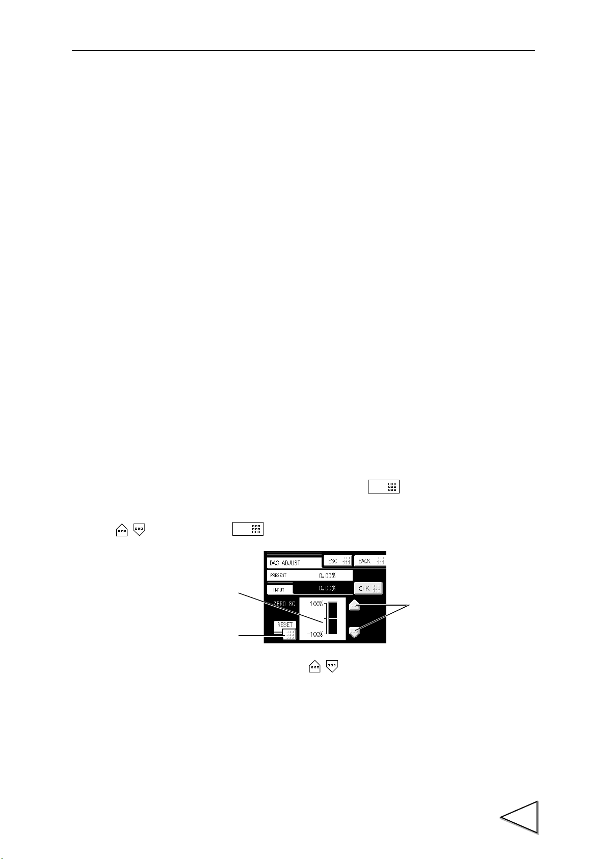
16-2. D/A Converter Setting
O K
O K
Reset key
Dummy trimmer position indicator
Dummy trimmer adjustment
UP/DOWN keys
■ D/A output mode
Alternatives: [GROSS] [NET] [ZERO SCALE] [FULL SCALE]
Explanation of each item
GROSS: Output is ganged with the gross.
NET: Output is ganged with the net.
ZERO SCALE: The output is fixed at zero output (0V or 4mA).
FULL SCALE: The output is fixed at full scale (10V or 20mA).
■ Zero output
Set the indicated value for outputting 4mA (0V).
Setting range: 0 ~ 99999
16.D/A CONVERTER (OPTION)
■ Full scale output
Set the indicated value for outputting 20mA (10V).
Setting range: 0 ~ 99999 (However, the preset zero output value should be smaller than
the preset full scale value.)
How to adjust
Adjust the output with the dummy trimmer that appears on the adjustment screen after selecting each
fixed output in the D/A output mode setting and pressing the key.
While monitoring the output value, finely adjust the output with the dummy trimmer the UP/DOWN
・ keys, and press the key to confirm, so that the trimmer position is entered.
*
Pressing the dummy trimmer
* The trimmer adjusting ranges are as follows: voltage; ±1.0V, and current; ±1.6mA.
* The reset key resets the dummy trimmer position to the trimmer center point (0%).
the UP/DOWN
・
keys
continuously performs continuous operation.
57
Page 67

17.ERROR MESSAGE
17. ERROR MESSAGE
“+LOAD” or “-LOAD”
Voltage exceeding the ADC input range is input.
Check to see if the output voltage of the loadcell exceeds the range, and check the cables for breaks.
This message is also displayed when wiring is incorrect or nothing is connected.
“NET OVER”
The net weight value exceeds the “NET OVER” set value. Check the “NET OVER” set value.
“GROSS OVER”
The gross weight exceeds the “GROSS OVER” set value. Check the “GROSS OVER” set value.
“GRAPH ERR”
[Cause]
The set value of the “Y-axis (load) start point” is larger than the set value of the “Y-axis (load) end
point”.
[Remedy]
Set again so that the “Y-axis (load) start point” becomes smaller than the “Y-axis (load) end point”.
“LOCK IS ON”
[Cause]
Key operation is locked.
[Remedy]
Please make the key operation "ON" referring to following instructions.
" ■ LOCK1/LOCK2" on page 31, " ■ 〔GROSS/NET〕key" on page 34, " ■ 〔DZ〕key" on
page 34, " ■ 〔TARE〕key" on page 34, " ■ 〔Cursor ON/OFF〕key" on page 34, " ■ 〔START/
STOP〕key" on page 34.
Moreover, please turn OFF external KEY_LOCK input when KEY_LOCK of B4 Function Selection is
set.
“SEQ. ERR 1”
[Cause]
The stop signal is ON when the weighing start signal is turned ON.
[Remedy]
Turn the stop signal OFF.
58
“SEQ. ERR 2”
[Cause]
The stop signal is turned ON during weighing in sequence control.
Page 68

17.ERROR MESSAGE
How to reset the sequence error
The sequence error is reset by inputting the stop signal (OFF → ON).
“SEQ. ERR 4”
[Cause]
The near zero signal is OFF when weighing is started.
(On condition that it is set to confirm the near zero signal when weighing is started.)
[Remedy]
First, check the preset near zero value and near zero comparison target.
Next, check to see if:
1. A start was made in spite of incomplete discharge.
2. The start ON timing was too early.
3. Discharged items are jammed.
“SEQ. ERR 5”
[Cause]
1. The SP1 output is ON when weighing is started.
(On condition that it is set to confirm the weight value when weighing is started.)
2. Final weight – CPS ≦ 0.
[Remedy]
First, check the preset SP1 value, preset fall value, and preset final weight value.
Next, check to see if:
1. A start was made in spite of incomplete discharge.
2. The start ON timing was too early.
3. Discharged items are jammed.
4. Another code was selected.
59
Page 69

18.SELF-CHECK
Star t
ESC
Bright
Dark
Light Out
Trns.
18. SELF-CHECK
Self-check is performed when the setting is called.
■ Self-check DSP1
Check the display to see that it is free from color and display defects, etc. The screen changes from red,
green, blue, horizontal stripes, to vertical stripes. Touching the screen restores the previous screen.
■ Self-check MEM
Check the memory to see that it is free from defects. The result is
displayed in a moment after the key at the lower right of the
screen is pressed. Or, check the version here.
■ Self-check KEY
Check the touch panel to see that it is free from unrecognized parts.
One touched square turns yellow. Pressing the key at the upper
right of the screen restores the previous screen
■ Self-check EXT
Check the operations of the external input/output signals.
Each output turns on when the corresponding key is pressed.
Each input turns green when its ON state is recognized.
■ Self-check DSP2
Check the backlight and status indicator lamp.
The backlight turns bright by pressing " " button, and turns
dark by pressing " " button.
The backlight goes out when the " " button is pressed, and after
that, it recovers when the screen is touched.
The status indicator lamp lights in green and orange alternately.
■ Self-check COM
The data displayed under "Transmit data" is sent by pressing the
key.
Under "Receive data", externally transmitted data is displayed.
60
Page 70

19. BLOCK DIAGRAM
Lithem
battery
Low-pass
Fillter
SHIELD
FRAME
×100
MPU
+5VI +12VI -9VA +5VD
DigitalIsolation
Power Supply Unit
+9VA
Serial
Port
Port
Port
Serial
Port
Port
Watch
Dog
CPU
32bit
RAM
16kbyte
NOV.RAM
4096bit
LCD
Driver
LCD
Flash
ROM
SI/F
DeviceNet
BCD
256kbyte
+EXC
-EXC
+SIG
-SIG
+S
-S
Analogue
External
SRAM
External
Flash
ROM
Serial
Port
RS-232C
CC-Link
D/A
(DAVorDAI)
Option
Standard
A/D
Converter
Referrence
Voltage
Excitation
Voltage
Control
Input
11Line
Control
Input
9Line
To uc h
Panel
Input
AC IN
FRAME
19.BLOCK DIAGRAM
61
Page 71
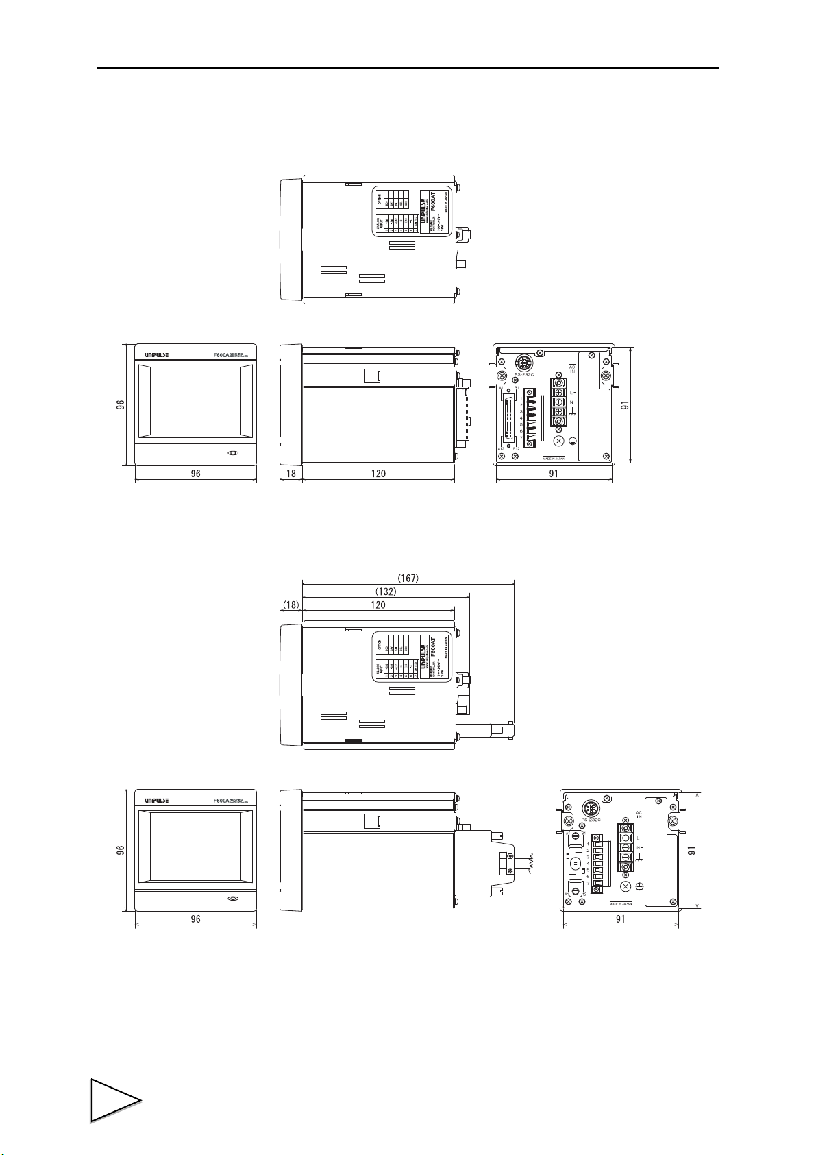
20.DIMENSIONS
Unit: mm
< Front ><Side ><Rear >
<
To p >
Unit: mm
< Front ><Side ><Rear >
<
To p >
20. DIMENSIONS
■ Standard equipment
■ When the external input/output signals is connected
62
Page 72
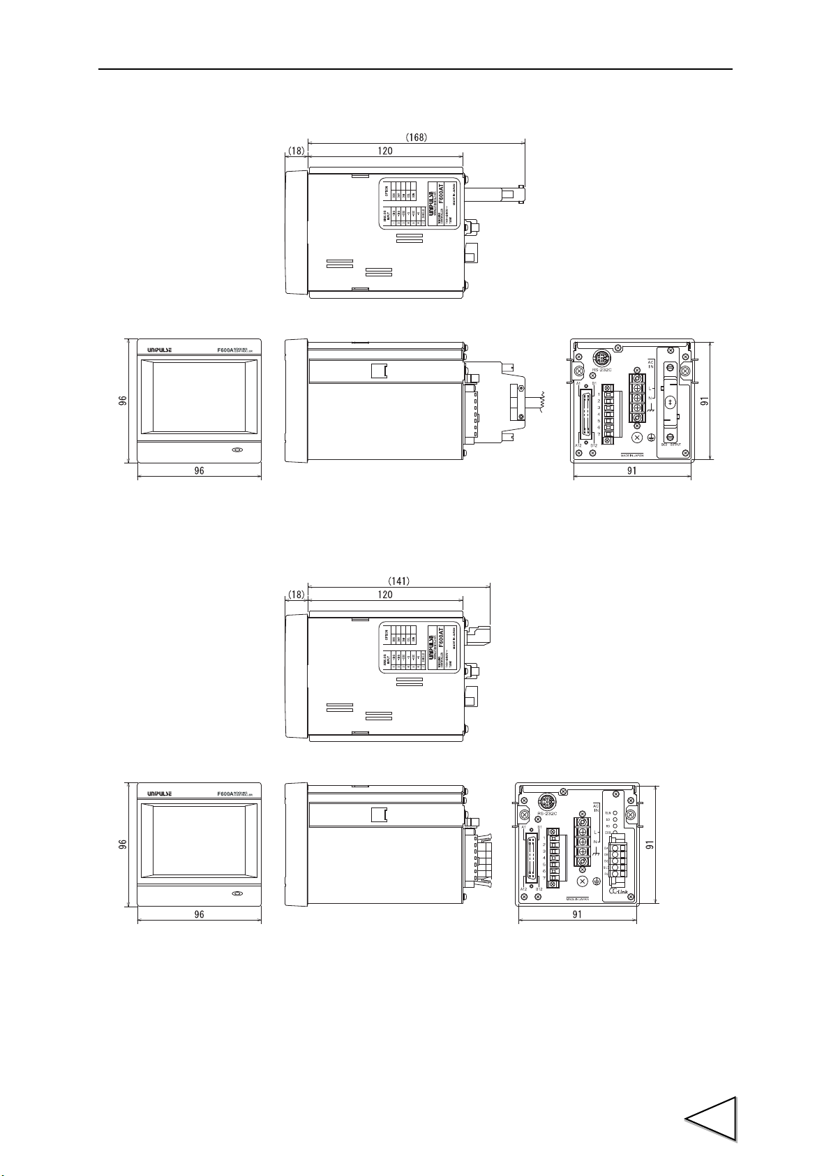
■ When the BCD option is equipped
Unit: mm
< Front ><Side ><Rear >
<
Top >
Unit: mm
< Front ><Side ><Rear >
<
Top >
20.DIMENSIONS
■ When the CC-Link option is equipped
63
Page 73

20.DIMENSIONS
Unit: mm
< Front ><Side ><Rear >
<
Top >
Panel-cut
Panel thickness
92mm
+1
-
0
1.6 to 3.2mm
92mm
+1
-
0
dimensions
■ When the DeviceNet option is equipped
20-1. Installation in a Panel
To install the F600AT into a control panel, use the following procedure.
1. Make a hole in the panel according to the panel-cut
dimensions.
2. Remove the screws (two), and remove the guide rails
from both sides.
* Do not use other screws than those installed to
the F600AT body
3. Fit in the F600AT from the front of the panel.
4. Install from the rear the guide rails having been
removed from both sides in Step 2, and fix them with
the screws (two).
64
Page 74

21. SETTING ITEM LIST
* L1: Setting that LOCK is controlled by LOCK1
* L2: Setting that LOCK is controlled by LOCK2
* S: Saved in SRAM (Lithium-battery-backed-up)
* N: Saved in NOV.RAM (Saved in non-volatile memory)
EACH CODE (Comparison mode: HI-LO COMP)
21.SETTING ITEM LIST
PAG E
1 HH 000.00
2 HI 000.00
1
3 LO 000.00
4 LL 000.00
Parameter Initial value L1 L2 S
CODE 0
EACH CODE (Comparison mode: DIS.-O/U)
PAG E
1 FINAL 000.00
2 SP1 000.00
1
3 SP2 000.00
4 CPS 00.00
5 AFFC 098.00
2
6 OVER 0.00
7 UNDER 0.00
Parameter Initial value L1 L2 S
CODE 0
N
○
〇〇
〇〇
〇〇
〇〇
N
○
〇〇
〇〇
〇〇
〇〇
〇〇
〇〇
〇〇
Alternatives・Setting range
0 ~ 7 00(R/W)
±00000 ~ ±99999 01(R/W)
±00000 ~ ±99999 02(R/W)
±00000 ~ ±99999 03(R/W)
±00000 ~ ±99999 04(R/W)
Alternatives・Setting range
0 ~ 7 00(R/W)
00000 ~ 99999 11(R/W)
00000 ~ 99999 12(R/W)
00000 ~ 99999 13(R/W)
0000 ~ 9999 14(R/W)
00000 ~ 99999 15(R/W)
000 ~ 999 16(R/W)
000 ~ 999 17(R/W)
Communication
Command
No.
Communication
Command
No.
EACH CODE (Comparison mode: DIS.-H/L)
PAG E
1 FINAL 000.00
2 SP1 000.00
1
3 SP2 000.00
4 CPS 00.00
5 AFFC 098.00
2
6 HI 000.00
7 LO 000.00
Parameter Initial value L1 L2 S
CODE 0
N
○
〇〇
〇〇
〇〇
〇〇
〇〇
〇〇
〇〇
Alternatives・Setting range
0 ~ 7 00(R/W)
00000 ~ 99999 11(R/W)
00000 ~ 99999 12(R/W)
00000 ~ 99999 13(R/W)
0000 ~ 9999 14(R/W)
00000 ~ 99999 15(R/W)
±00000 ~ ±99999 02(R/W)
±00000 ~ ±99999 03(R/W)
Communication
Command
No.
65
Page 75

21.SETTING ITEM LIST
COMPARISON
PAG E
Parameter Initial value L1 L2 S
1 COMP MODE SEL. HI-LO COMP
2 COMP. INH. TIME 0.50sec.
1
3 JUDGING TIME 1.50sec.
4 COMPLETE OUT T. 3.00sec.
5 AFFC ON
6 CPS. COFFICIENT 1/1
7 AVG. CNT OF AFFC 4times
8 DIS. CONTROL MODE FEEDING
2
9 COMPLETE SIG. OUT
10 OVER/UNDER COMP. REGULARLY
11 HI/LO COMP. SEL GROSS
12 NEAR ZERO COMP. GROSS
3
13 PRESET TARE WGT.1 ON
14 NEAR ZERO 000.00
15 PRESET TARE WGT.2 000.00
JUDGING
TIME
N
〇〇
〇〇
〇〇
〇〇
〇〇
〇〇
〇〇
〇〇
〇〇
〇〇
〇〇
〇〇
〇〇
〇〇
〇〇
Alternatives・Setting range
0:[HI-LO COMP]1:[DIS.-O/U]
2:[DIS.-H/L]
0.00 ~ 9.99 32(R/W)
0.00 ~ 9.99 33(R/W)
0.00 ~ 9.99 34(R/W)
0:[OFF] 1:[ON]
0:[1/1]1:[3/4]2:[2/4]3:[1/4]
1 ~ 9 37(R/W)
0:[FEEDING]1:[DISCHARGE]
2:[EXTERNAL]
0:[JUDGING TIME]1:[JUD.or STABLE
2:[JUD.& STABLE
]
0:[REGULARLY]1:[COMP. SIG.]
2:[EXT. IN]3:[COMP. SIG&H]
0:[GROSS]1:[NET]2:[COMP OFF
0:[GROSS]1:[NET]
2:[COMP OFF]3:[ABS GROSS]
4:[ABS NET]
0:[OFF]1:[ON]
00000 ~ 99999 3E(R/W)
00000 ~ 99999 3F(R/W)
Communication
Command
]
]
No.
31(R/W)
35(R/W)
36(R/W)
38(R/W)
39(R/W)
3A(R/W)
3B(R/W)
3C(R/W)
3D(R/W)
OPERATION
PAG E
1 DIGITAL FILTER 16times
1
2 ANALOG FILTER 6Hz
3 MD (PERIOD) 1.5sec.
4 MD (RANGE) 10CNT
5 DISPLAY FREQ. 10times
6 ZT (PERIOD) 0.0sec.
7 ZT (RANGE) 00CNT
8
2
9 INDICATE COLOR Yellow
10
11 DISPLAY SELECT
12 HI/LO OUT SEL
3
13 LOCK1 OFF
14 LOCK2 OFF
Parameter Initial value L1 L2 S
BACKLIGHT
BRIGHT-AND-DARK TIME
BACKLIGHT
LIGHTING TIME
(*) It changes with comparison modes. (Refer to page 30.)
0minute
10minutes
HH,H,L,LL (*)
NORMAL
N
〇〇
〇〇
0:[2Hz]1:[4Hz]2:[6Hz]3:[8Hz
〇〇
〇〇
〇〇
〇〇
〇〇
〇〇
〇〇
〇〇
〇〇
〇〇
0:[NORMAL]1:[COMPARATOR]
〇
〇
Alternatives・Setting range
0:[OFF]1:[2times]2:[4times]
3:[8times]4:[16times]
5:[32times]6:[64times]
7:[128times]8:[256times]
0.0 ~ 9.9 43(R/W)
00 ~ 99 44(R/W)
01 ~ 10 45(R/W)
0.0 ~ 9.9 46(R/W)
00 ~ 99 47(R/W)
00 ~ 99 48(R/W)
0:[Ye ll ow ]1:[Green]
2:[Blue]3:[Comparison]
00 ~ 99 4A(R/W)
0:[F, S P 1 - 3]1:[F, S P 3, H , L]
2:[F, S P 3 , T, Z ] (*)
0:[OFF]1:[ON]
0:[OFF]1:[ON]
]
Communication
Command
No.
41(R/W)
42(R/W)
49(R/W)
4B(R/W)
4C(R/W)
4D(R)
4E(R)
66
Page 76
GRAPH
21.SETTING ITEM LIST
PAG E
Parameter Initial value L1 L2 S
1 GRAPHIC MODE CONTINUITY
2 TRIGGER LEVEL 001.00
1
3 X END POINT 10sec.
4 Y START POINT 000.00
5 Y END POINT 100.00
2 6 DRAWING WEIGHT
NET
OPTION (In case of used BCD OUTPUT)
PAG E
1 DATA UPDATE RATE 100times
1
2 OUTPUT WEIGHT INDICATE
Parameter Initial value L1 L2 S
OPTION (In case of used D/A OUTPUT)
PAG E
1
1
2
3
Parameter Initial value L1 L2 S
D/A OUTPUT MODE GROSS
ZERO OUTPUT 000.00
FULLSCALE OUT. 100.00
〇〇
〇〇
〇〇
〇〇
〇〇
〇〇
〇〇
〇〇
〇〇
〇〇
〇〇
N
Alternatives・Setting range
0:[CONTINUITY]1:[SINGLE]
2:[LEVEL]
00000 ~ 99999 52(R/W)
2 ~ 98 53(R/W)
±00000 ~ ±99999 54(R/W)
±00000 ~ ±99999 55(R/W)
0:[GROSS]1:[NET]
N
Alternatives・Setting range
0:[100times]1:[50times]
2:[20times]3:[10times]
4:[5times]5:[2times]
0:[INDICATE]1:[GROSS]2:[NET]
N
Alternatives・Setting range
0:[GROSS]1:[NET]
2:[ZERO SCALE]3:[FULL SCALE]
00000 ~ 99999
00000 ~ 99999
Communication
Command
No.
51(R/W)
56(R/W)
Communication
Command
No.
Communication
Command
No.
OPTION (In case of used CC-Link)
PAG E
1 OCCUPIED STATION 4 stations
2 SPEED 10Mbps
1
3 STATION NUMBER 1
4 WGT SELECT CODE Extinput
Parameter Initial value L1 L2 S
OPTION (In case of used DeviceNet)
PAG E
1 NODE ADDRESS 0
2 SPEED 500kbps
1
3 WGT SELECT CODE Extinput
4 COMM. MODE Read only
Parameter Initial value L1 L2 S
N
〇〇
〇〇
〇〇
〇〇
N
〇〇
〇〇
〇〇
〇〇
Alternatives・Setting range
0:[1 station]1:[2 stations]
2:[4 stations]
0:[156kbps]1:[625kbps]
2:[2.5Mbps]3:[5Mbps]
4:[10Mbps]
~ 64
1
0:[Network]1:[Extinput]
Alternatives・Setting range
0
~ 63
0:[125kbps]1:[250kbps]
2:[500kbps]
0:[Network]1:[Extinput]
0:[Read only]1:[Write En.]
Communication
Command
No.
Communication
Command
No.
67
Page 77

21.SETTING ITEM LIST
SYSTEM
PAG E
Parameter Initial value L1 L2 S
N
Alternatives・Setting range
1 INITIALIZATION CODE
2 SELFCHECK DSP1
1
3 SELFCHECK MEM
[CODE][COMP.][OPR.]
4 SELFCHECK KEY
5 SELFCHECK EXT
6 SELFCHECK DSP2
7 SELFCHECK COM
8 PASSWORD 0000 0000 ~ 9999
2
9 LANGUAGE JPN
10 [GROSS/NET] KEY ON
11 [DZ] KEY ON
12 [TARE] KEY ON
3
13 [CURSOR ON/PFF] KEY ON
14 [START/STOP] KEY ON
15 B4 FUNC. SELECT CODE2
〇〇
〇〇
〇〇
〇〇
〇〇
〇〇
〇〇
CALIBRATION
[CAL.][etc.]
0: [JPN]1:[ENG]
0:[OFF]1:[ON]
0:[OFF]1:[ON]
0:[OFF]1:[ON]
0:[OFF]1:[ON]
0:[OFF]1:[ON]
Communication
Command
No.
69(R/W)
6A(R/W)
6B(R/W)
6C(R/W)
6D(R/W)
6E(R/W)
6F(R/W)
PAG E
Parameter Initial value L1 L2 S
1ZERO CAL. 0
2 SPAN CAL. 100.00
1
3 EQUIV. CAL. 3.000mV/V
4 BALANCE WEIGHT 100.00
5 MIN. SCALE DIV. 0.01
6 NET OVER 999.99
7 GROSS OVER 999.99
8 UNIT DISPLAY kg
2
9 DECIMAL PLACE 0.00
10 DZ REGULATION VAL 02.00
N
〇〇
〇〇
〇〇
〇〇
〇〇
〇〇
〇〇
〇〇
〇〇
〇〇
Alternatives・Setting range
[OK]
00001 ~ 99999
(VOL.) 0.001 ~ 3.000mV/V
(WEIGHT) 00001 ~ 99999
00001 ~ 99999 84(R/W)
001 ~ 100 85(R/W)
00000 ~ 99999 86(R/W)
00000 ~ 99999 87(R/W)
0:[NONE]1:[kg]2:[t]3:[g]
4:[N]5:[lb]
0:[NONE]1:[0.0]2:[0.00]
3:[0.000]
0000 ~ 9999 8A(R/W)
Communication
Command
No.
Command
Command
83(R/W)
88(R/W)
89(R/W)
68
Page 78

SEQUENCE MODE
21.SETTING ITEM LIST
PAG E
1
1
2
3
4
Parameter Initial value L1 L2 S
SEQUENCE MODE
ADJUST FEEDING
AT START NZ CONF.
AT START WV CONF.
5 ADJ.FEEDING TIME 1.00sec.
6 AZ TIMES 01times
2
7 JUDGING TIMES 01times
RS-232C
PAG E
1 COMM. MODE HAND SH.
2 BAUD RATE 9600BPS
1
3 LENGTH 8BIT
4 PARITY BIT ODD
5 STOP BIT 1BIT
6 TERMINATOR CR+LF
2
7 FLOW CONTROL OFF
Parameter
SIMPLE COMP.
OFF
OFF
OFF
Initial
valueInitial
value
〇〇
〇〇
〇〇
〇〇
〇〇
〇〇
〇〇
L1 L2 S
〇〇
〇〇
〇〇
〇〇
〇〇
〇〇
〇〇
N
Alternatives・Setting range
0:[SIMPLE COMP.] 1:[SEQUENCE]
0:[OFF]1:[ON]
0:[OFF]1:[ON]
0:[OFF]1:[ON]
0.00 ~ 9.99 95(R/W)
00 ~ 99 96(R/W
00 ~ 99 97(R/W)
N
Alternatives・Setting range
0:[HAND SH.]1:[CONTINUITY]
2:[AT PRINT]
0:[1200]1:[2400]2:[4800]
3:[9600]4:[19200]
0:[7bit]1:[8bit]
0:[NONE]1:[ODD]2:[EVEN]
0:[1bit]1:[2bit]
0:[CR]1:[CR+LF]
0:[OFF]1:[RTS/CTS]
Communication
Command
No.
91(R/W)
92(R/W)
93(R/W)
94(R/W)
Communication
Command
No.
D1(R)
D2(R)
D3(R)
D4(R)
D5(R)
D6(R)
DA(R)
69
Page 79

22.SPECIFICATIONS
22. SPECIFICATIONS
■ Analog Section
Sensor excitation 10V DC Output current: Within 120mA
6-wire (Up to four 350Ωload cells can be connected.)
Signal input range -0.2 to 3.0mV/V
Zero adjusting range -0.2 to 3.0mV/V
Accuracy Nonlinearity Within 0.02%FS ±1digit (When 3mV/V is input)
Zero drift Within 0.25μV/ ℃ RTI
Gain drift Within 25ppm/ ℃
A/Dconverter Speed 100times/sec.
Resolution 24bit (binary)
Analog filter Bessel type low-pass filter (-12dB/oct)
Cutoff frequency 2Hz, 4Hz, 6Hz, 8Hz (Selectable by setting)
Calibration Equivalent input calibration and actual load calibration
■ Display Section
Display 3.5 inch TFT color LCD module (Display area: 71mm×53mm)
320×240 dots
Weight value display 5-digit
Sign: Minus sign display
Minimum scale division Can be set in the range of 1 to 100.
Decimal point 8 8. 8. 8. 8 The display position can be set.
Over scale A/D converter input over: “LOAD”
A/D converter input minus over : “-LOAD”
Net weight exceeding the “NET OVER” setting: “NET OVER”
Gross weight exceeding the “GROSS OVER” setting: “GROSS OVER”
Unit display NONE, kg, t, g, N, lb is selectable.
Status display Various states of weight are displayed.
■ Setting section
How to set Set by touch panel operation (with a key click buzzer).
External setting can also be made by RS-232C etc..
70
Memory of set values Initial values NOV RAM (nonvolatile RAM)
Other values Lithium-battery-backed-up C-MOS RAM
(The memory life is approx. 7 years or more,
which varies depending on the operating conditions
and storage environment.)
Protection of set values Setting operation can be prohibited to prevent changes by misoperation.
(LOCK1, LOCK2)
Page 80

■ Communication
RS-232C communications interface
Asynchronous communication method
Baud rate 1200bps to 19200bps
SI/F (2-wire serial interface)
2-wire serial interface for connecting a UNIPULSE-manufactured printer,
external display, etc.
Asynchronous communication method
Baud rate 600bps
■ Option
BCD data output Open collector output
The output rate can be changed.
D/A converter Voltage output 0 to 10V
Current output 4 to 20mA
CC-Link Number of occupied stations 1, 2, 4 STAT.
Baud rate 156k, 625k, 2.5M, 5M, 10Mbps
Station number 1 to 64 (when one station is occupied)
1 to 63 (when two station is occupied)
1 to 61 (when four station is occupied)
22.SPECIFICATIONS
DeviceNet Baud rate 125k, 250k, 500kbps
Node address 0 to 63
■ External Input/Output
External output signal Transistor open collector output. (Emitter = COM terminal)
(9 points) The output turns ON when the transistor turns ON.
External input signal ON when shorted with COM terminals by contact (relay, switch, etc.) or
(11 points) non-contact (transistor, TTL open-collector output, etc.)
■ General Performance
Required power supply AC spec. AC100V to AC240V (+10% -15%)
[
Free power supply 50/60Hz
DC spec. DC24V (±15%)
(Depending on the request at the time of order)
Power consumption AC spec. 18W max
DC spec. 18W max
Operating conditions Temperature Operating temperature range: -10 ℃ to +40 ℃
Storage temperature range: -20 ℃ to +60 ℃
Humidity 80%RH or less (non-condensing)
]
Dimensions 96W × 96H × 138D (mm) (not including projections)
Weight Approx.1.0kg
71
Page 81

 Loading...