

Page 1

F395
DYNAMIC FORCE PROCESSOR
Operation Manual
10 Apr. 2012
Rev. 1.12
Page 2

Introduction
We appreciate your kind purchase of F395 Dinamic Force Processor.
To take full advantage of high performance of F395, Thoroughly read this operating
manual first before use and understand the explanations contained herein for correct
operating procedures.
Introduction
Page 3

Safety Precautions
Be sure to read for safety.
In order to have an F395 Dinamic Force Processor used safely, notes I would like you to
surely follow divide into and , and are indicated by the following
documents.Notes indicated here are the serious contents related safely.Please use after
understanding the contents well.
WARNING
CAUTION
WARNING
Misuse may cause the risk of death or serious
injury to persons.
CAUTION
Misuse may cause the risk of injury to persons
or damage to property.
Safety Precautions
Page 4

WARNING
● Use F395 with correct supply voltage.
● Do not carry out the direct file of the commercial power supply to a signal input terminal.
● Carefully check wiring, etc. before applying power.
● Set the correct Excitation Voltage for the sensor. (10V is set when F340A is
dispatched from us.)
● Do not disassemble the main body for modifications or repair.
● Be sure to ground the protective ground terminal.
● When smoke, a nasty smell, or strange sound, please shut off a power supply
immediately and extract a power supply cable.
● Do not install in the following environments.
- Places containing corrosive gas or flammable gas.
- Where the product may be splashed with water, oil or chemicals.
● About the built-in lithium battery
Never disassemble, deform under pressure or throw the battery
into fire.The battery may explode, catch fire or leak.
- Battery
Model: CR14250SE made by SANYO Electric Co., Ltd.
Nominal voltage: 3V
Nominal electric capacity: 850mAh
Safety Precautions
Page 5

Safety Precautions
CAUTION
● Be sure to disconnect the power cable when performing the following.
- Attachment/detachment of connectors of options.
- Wiring/connection of cables to terminal blocks.
- Connection of the ground line.
● Take an interval of more than 5 seconds when repeating ON/OFF.
● For connection to the signal I/O terminal block, wire correctly after checking the signal
names and terminal block numbers.
Also, turn off the power of the main body before connection/wiring to the signal I/O
terminal block.
● Use shielded cables for the connection of strain gauge type sensor, displacement
sensor, External input and output or options.
● Take adequate shielding measures when using at the following locations.
- Near a power line.
- Where a strong electric field or magnetic field is formed.
- Where static electricity, relay noise or the like is generated.
● Do not install in the following environments.
- Where the temperature and/or humidity exceeds the range in the specifications.
- Places with large quantities of salt or iron powder.
- Where the main body is directly affected by vibration or shock.
● Do not use it, broken down.
● When you send F395 by repair etc., please take sufficient measures against a shock.
Page 6

RoHS-compliant product
Please inquire of our sales person about the RoHS-compliance of the option.
The parts and attachments (including the instruction manual, packaging box, etc.) used
for this unit are compliant with the RoHS Directive restricting the use of hazardous
substances with regard to adverse effects on the environment and human body.
What is RoHS?
It is an abbreviation for Restriction on Hazardous Substances, which is implemented by
the European Union (EU). The Directive restricts the use of six specific substances in
electric and electronic equipment handled within EU borders. The six substances are
lead, mercury, cadmium, hexavalent chromium, PBB (polybrominated biphenyls), and
RoHS-compliant product
PBDE (polybrominated diphenyl ethers).
Page 7

Contents
Contents
Per Reading This Instruction Manual ........................................1
1.Outline of the F395 ................................................................2
1-1.What the F395 Can Do: ............................................................................. 2
1-2.Waveform Drawing Procedures ............................................................... 3
1-3.Multi-Hold Procedures .............................................................................. 3
1-4.Hysteresis Procedures .............................................................................. 4
1-5.Hysteresis 2 Procedures ........................................................................... 4
1-6.Waveform Comparison /
Waveform and Displacement Comparison Procedures ......................... 5
1-7.Operation Mode at a Glance ..................................................................... 5
1-8.Standard Interface ..................................................................................... 6
1-9.Waveform Reading .................................................................................... 6
2.Name and Function of Each Part .........................................7
2-1.Front Pane .................................................................................................. 7
2-1-1.Touch Panel Type Color Liquid Crystal Display ........................................ 7
2-2.Rear Panel ................................................................................................ 11
3.Screen Configuration and Setting Methods ......................13
3-1.Screen Flow Chart ................................................................................... 13
3-2.Setting Mode Tree Chart ......................................................................... 15
3-3.Setting Methods ....................................................................................... 17
3-3-1.Specification of Setting Items ................................................................... 17
3-3-2.Unit Setting Method .................................................................................... 18
4.Methods of Connection .......................................................20
4-1.Connection to the Cage Clamp Type Terminal Block .......................... 20
4-1-1.Analog Input / Output Connection ............................................................ 21
Page 8

Contents
4-1-1-1.Analog Input / Output Terminal Pin Assignments .......................................................... 21
4-1-1-2.Strain Gauge Sensor Connection .................................................................................... 22
4-1-1-3.Voltage / Current Type Sensor Connection .................................................................... 23
4-1-1-4.Voltage Output (V-OUT) Connection ................................................................................ 23
4-1-2.SI/F Connection .......................................................................................... 23
4-2.RS-232C Connection ............................................................................... 24
4-2-1.RS-232C Connector .................................................................................... 24
4-2-2.Connector Pin Assignments ..................................................................... 24
4-2-3.Example of Cabling .................................................................................... 24
4-3.Control Connector Connection .............................................................. 25
4-3-1.Connector Pin Assignments ..................................................................... 25
4-3-2.Input and Output Signals ........................................................................... 25
4-3-3.Equivalent Circuit (Input) ........................................................................... 30
4-3-4.Equivalent Circuit (Output) ........................................................................ 30
5.Methods of Calibration ........................................................31
5-1.What is Calibration? ................................................................................ 31
5-2.CH1 Input Calibration and CH2 Input Calibration ................................. 31
5-3.Equivalent Input Calibration Procedures .............................................. 32
5-4.Actual Load Calibration Procedures ..................................................... 33
5-5.LOCK Release .......................................................................................... 34
5-6.Excitation Voltage ................................................................................... 34
5-7.Unit ............................................................................................................ 35
5-8.Increment ................................................................................................. 35
5-9.Decimal Place .......................................................................................... 35
5-10.Zero Calibration ..................................................................................... 35
5-11.Equivalent Input Calibration ................................................................. 36
5-12.Actual Load Calibration ........................................................................ 37
6.Settings and Operations Relating to Indicated Values ....38
6-1.Digital Filter .............................................................................................. 38
6-2.Analog Filter ............................................................................................. 38
6-3.Digital Offset ............................................................................................ 38
6-4.Digital Zero ............................................................................................... 39
Page 9

Contents
7.Measurement Operation Functional Settings ...................40
7-1.Operation Mode ....................................................................................... 40
7-2.Sampling Rate .......................................................................................... 40
7-3.Sampling Reset ........................................................................................ 41
7-4.X/Y-axis Setting by Operation Mode and Input CH .............................. 41
8.Hold Point Display Screen ..................................................42
9.Method of Starting Measurement .......................................43
10.Multi-Hold Mode .................................................................47
10-1.Function ................................................................................................. 47
10-2.Setting and Operating Method ............................................................. 47
10-3.Hold Functions ...................................................................................... 48
10-3-1.Sample Hold .............................................................................................. 49
10-3-2.Peak Hold .................................................................................................. 50
10-3-3.Valley Hold ................................................................................................ 51
10-3-4.P-P (Peak-to-Peak) Hold ........................................................................... 52
10-3-5.Period Specified Hold (Peak, Valley, P-P) .............................................. 53
10-3-6.Time Specified Hold (Peak, Valley, P-P) ................................................. 54
10-3-7.Time Specified Automatic Hold (Peak, Valley, P-P) .............................. 55
10-3-8.Relative Maximum Value / Relative Minimum Value Hold .................... 56
10-3-9.Four Types of Inflection Point Hold ........................................................ 57
10-3-9-1.Inflection Point Hold A ....................................................................................................58
10-3-9-2.Inflection Point Hold B ....................................................................................................59
10-3-9-3.Inflection Point Hold C ....................................................................................................60
10-3-9-4.Inflection Point Hold D ....................................................................................................61
10-3-10.Pulse Hold ............................................................................................... 62
11.Hysteresis Mode ................................................................64
11-1.Function ................................................................................................. 64
11-2.Setting and Operating Method ............................................................. 64
12.Hysteresis 2 ........................................................................65
Page 10

12-1.Function ................................................................................................. 65
12-2.Setting and Operating Method ............................................................. 65
13.Waveform Comparison / Waveform and
Displacement Comparison Mode .....................................68
13-1.Function ................................................................................................. 68
13-2.Setting and Operating Method ............................................................. 68
13-3.Waveform Sampling Procedures ......................................................... 69
13-4.Waveform Comparison Mode ............................................................... 73
13-5.Waveform and Displacement Comparison Mode ............................... 74
13-5-1.Scale of the X-axis .................................................................................... 74
13-5-2.Handling of Sudden Changes ................................................................. 74
Contents
13-5-3.Updating the Amount of Displacement .................................................. 75
13-6.Timing in the Waveform Comparison /
Waveform and Displacement Comparison Mode ............................... 76
13-7.Hold Operation ....................................................................................... 78
13-7-1.Operation and Operating Method ........................................................... 78
13-7-2.Setting Method .......................................................................................... 80
13-8.Un-passing Area Output ....................................................................... 80
13-9.Display After Measurement .................................................................. 81
14.Waveform Editing ..............................................................82
14-1.Waveform Call-up .................................................................................. 82
14-2.Waveform Clear ..................................................................................... 82
14-3.Waveform Sampling .............................................................................. 83
14-4.Waveform Editing .................................................................................. 84
14-4-1.Tie Drawing ............................................................................................... 86
14-4-1-1.Tie Drawing Procedures .................................................................................................. 86
14-4-1-2.About Deletion of Previously Prepared Points .............................................................88
14-4-1-3.About the Help Function ................................................................................................. 88
14-4-2.Shift ............................................................................................................ 89
14-4-2-1.Shift Procedures ..............................................................................................................89
14-4-3.Area Setting .............................................................................................. 90
14-4-3-1.Area Setting Procedures ................................................................................................. 91
14-4-4.Waveform Save ......................................................................................... 91
Page 11

Contents
15.Waveform Reading ............................................................92
15-1.Waveform Reading ................................................................................ 92
15-1-1.Cursor Center Key .................................................................................... 94
15-1-2.Waveform Reading in the Hysteresis / Hysteresis 2 Mode ................... 94
15-1-3.Waveform Reading in the Waveform Comparison / Waveform and
Displacement Comparison Mode ............................................................ 95
15-1-4.Hold Jump Function ................................................................................. 95
15-1-5.Simple Call-up of the Waveform Reading Screen ................................. 96
15-1-6.Display of Hold Point in the Read Waveform ......................................... 96
15-2.Rejected Waveform Reading ................................................................ 96
15-3.Rejected Waveform Clear ..................................................................... 97
15-4.Y-axis Start Point ................................................................................... 97
15-5.Y-axis Scaling ........................................................................................ 97
15-6.X-axis Start Point ................................................................................... 98
15-7.X-axis Scaling ........................................................................................ 98
15-8.Control Signal Display .......................................................................... 99
16.Code Setting .....................................................................100
16-1.Method of Setting the Operation ch ................................................... 100
16-2.Each Setting Item ................................................................................ 103
16-2-1.Channel Number Selection .................................................................... 103
16-2-2.Parameter Copy ...................................................................................... 104
16-2-3.Select Analog CH .................................................................................... 104
16-2-4.Hold Setting ............................................................................................ 105
16-2-5.Auto Code Up / Code Up Point .............................................................. 107
16-2-6.High-Low Relative .................................................................................. 108
16-2-7.High Limit / Low Limit / HI-HI/LO-LO Mode / HI-HI Limit /
LO-LO Limit ............................................................................................ 109
16-2-8.Displacement High-low Mode / Displacement High Limit /
Displacement Low Limit / Displacement Hold High Limit /
Displacement Hold Low Limit ............................................................... 110
16-2-9.Level Axis Select / Waveform Start Level /
Waveform Termination Level / Hold Start Level .................................. 113
16-2-10.Hold Detect Time .................................................................................. 115
16-2-11.Minimum Peak and Valley Difference /
Peak and Valley Detection Rate / Peak and Valley Ordinal .............. 116
16-2-12.Minimum Slope Detection Value / Slope Detection Interval A /
Slope Detection Interval B / Preliminary Slope Detection Point ...... 118
Page 12

Contents
16-2-13.Inhibit Timer .......................................................................................... 119
16-2-14.Hysteresis Interval ................................................................................ 119
16-2-15.Forced-termination Limit ..................................................................... 120
16-2-16.Forced-termination Output .................................................................. 120
16-2-17.Un-passing Area Output ...................................................................... 120
16-3.Graph Confirmation ............................................................................. 121
16-3-1.Items to be Displayed on the Graph of the Present Value and
Input Value .............................................................................................. 122
16-3-2.Minimum Peak and Valley Difference ................................................... 123
16-3-3.Peak and Valley Detection Rate ............................................................ 123
16-3-4.Peak and Valley Ordinal ......................................................................... 124
16-3-5.Minimum Slope Detection Value ........................................................... 124
16-3-6.Slope Detection Interval A ..................................................................... 125
16-3-7.Slope Detection Interval B ..................................................................... 125
16-3-8.Preliminary Slope Detection Point ........................................................ 126
16-3-9.Hysteresis Interval .................................................................................. 126
17.System-related Settings and Operations ......................127
17-1.Set Value Protection ............................................................................ 127
17-2.Display Update Rate ............................................................................ 127
17-3.Backlight .............................................................................................. 127
17-4.Contrast ................................................................................................ 128
17-5.All Parameters Clear ........................................................................... 128
17-6.Self-test ................................................................................................ 128
17-7.Self-test of ROM & RAM / Self-test of NOV-RAM .............................. 131
17-8.Pass Word ............................................................................................ 131
17-9.Switching between Japanese and English ....................................... 131
18.Interface ............................................................................132
18-1.SI/F 2-wire Serial Interface .................................................................. 132
18-2.RS-232C Interface ................................................................................ 133
18-2-1.Communication Specifications ............................................................. 133
18-3.Interface-related Settings ................................................................... 133
18-3-1.Transmission Speed .............................................................................. 133
18-3-2.Character Length .................................................................................... 134
Page 13

Contents
18-3-3.Parity ........................................................................................................ 134
18-3-4.Terminator ............................................................................................... 134
18-3-5.Communication Mode ............................................................................ 134
18-3-6.SI/F Hold Point Transmission ................................................................ 134
18-3-7.SI/F Hold Point ........................................................................................ 134
18-4.RS-232C Format ................................................................................... 135
18-4-1.Writing Set Values .................................................................................. 135
18-4-2.Reading Set Values ................................................................................ 138
18-4-3.Specifying Sampled Waveform Access Channels .............................. 139
18-4-4.Writing Sampled Waveform Data .......................................................... 140
18-4-5.Reading Sampled Waveform Data ........................................................ 142
18-4-6.Writing the Effective Area of the Sampled Waveform ......................... 143
18-4-7.Reading the Effective Area of The Sampled Waveformend of
the Area ................................................................................................... 144
18-4-8.List of Accessible Waveforms by Operation Mode ............................. 145
18-4-9.Reading Indicated Values / Status ........................................................ 146
18-4-10.Commands ............................................................................................ 147
18-4-11.Reading Hold Data ................................................................................ 147
18-4-12.Automatic Transmission Mode ........................................................... 149
19.Error Messages ................................................................150
19-1.Details of Messages ............................................................................ 150
19-2.Method of Checking ADC+OVER / ADC-OVER ................................. 151
20.Block Diagram ..................................................................152
21.Outer Dimensions ............................................................153
22.Mounting to a Panel .........................................................154
23.Specifications ..................................................................155
23-1.Analog Input Section ........................................................................... 155
23-2.Pulse Input Section ............................................................................. 157
23-3.Display Section .................................................................................... 157
23-4.Setting Section .................................................................................... 158
23-5.Input / Output Section ......................................................................... 158
Page 14

Contents
23-6.External Power Supply (Shared with Excitation Voltage) ................ 158
23-7.Interface ................................................................................................ 158
23-8.General Performance .......................................................................... 159
23-9.Option ................................................................................................... 159
23-10.Accessories ....................................................................................... 160
24.Setting Items list ..............................................................161
25.Statement of Conformation to EC Directives ................163
Page 15

Per Reading This Instruction Manual
Per Reading This Instruction Manual
Since various names on the F395 are determined by assuming the X-axis sensor
displacement input, matters relating to the X-axis input may be expressed as
displacement - depending on the description in this instruction manual.
1
Page 16

1. Outline of the F395
Sampling of waveform variation with
displacement for going and return,
detection of points in a waveform such
as an inflection point, and judgment of
differences between going and return
at a given point
(Hysteresis / Hysteresis 2 function);
Connection (P.21 )
Calibration (P.31 )
Settings Relating to Indicated
Value (P.38 )
Reading of Waveform (P.92 )
Measurement Operation
Functional Settings (P.40 )
Multi-Hold, (P.47 )
etc.
Waveform Comparison /
waveform and Displacement
Comparison, (P.68 )
etc.
The procedures from waveform display to uses of the Multi-Hold function and Waveform Comparison
function are as follows:
The Multi-Hold / Hysteresis / Hysteresis 2 / Waveform Comparison / Waveform and
Displacement Comparison functions cannot be used simultaneously.
Carefully read the explanations of "7. Measurement Operation Functional Settings" P40,
"10. Multi-Hold Mode" P47, "11. Hysteresis Mode" P64, "12. Hysteresis 2" P65, "13.
Waveform Comparison / Waveform and Displacement Comparison Mode" P68 and select
function(s) appropriate for the equipment application you use.
Detection of points in a waveform such
as an inflection point
(Multi-Hold function);
Basically, the waveform between the START signal and STOP
signal is graphically drawn.
(Conditional. See "9. Method of Starting Measurement" P43.)
START
STOP
Hysteresis (P.64 )
Hysteresis 2 (P.65 )
etc.
Check to see if the waveform variation
with time and displacement is within a
certain width
(Waveform Comparison / Waveform
and Displacement Comparison
function).
Waveform display of signals from a
strain gauge type sensor;
Strain gauge type sensor
Request
1-1. What the F395 Can Do:
1.Outline of the F395
2
Page 17

1.Outline of the F395
1-2. Waveform Drawing Procedures
The F395 can provide waveform displays of signals from a strain gauge type sensor and
displacement sensor. The waveform display procedures are as follows.
(See "7-4. X/Y-axis Setting by Operation Mode and Input CH" P41.):
1. Connect a strain gauge type sensor (and displacement sensor) with the F395.
(See "4-1-1. Analog Input / Output Connection" P21.)
2. Perform calibration. (See "5. Methods of Calibration" P31.)
3. Set each parameter for waveform display.
(See "9. Method of Starting Measurement" P43, and "16-2-9. Level Axis Select /
Waveform Start Level / Waveform Termination Level / Hold Start Level" P113.)
4. Check to see if a waveform is displayed for the set conditions.
1-3. Multi-Hold Procedures
In the Multi-Hold mode, necessary points are detected in the displayed waveform to
make a judgment such as a High/Low Limit Comparison. Up to 32 channels of Hold
types, High and Low Limits, etc., can be stored, which can be switched by external
signals. The procedures for using the Multi-Hold function are as follows:
1. Check to see if a waveform is displayed in accordance with the waveform drawing
procedures. (See "1-2. Waveform Drawing Procedures" P3.)
2. Select a hold function so that necessary points in the waveform can be held. (See "10-
3. Hold Functions" P48.)
3. Carry out Multi-Hold settings. (See "16-2. Each Setting Item" P103.)
4. Select the channel number(s) you want to control externally. (See "4-3. Control
Connector Connection" P25.)
5. Input T/H and H/M signals in accordance with the selected hold function, and check to
see if operation is performed as set. (See "10-3. Hold Functions" P48.)
3
Page 18

1-4. Hysteresis Procedures
In the Hysteresis mode, go and return waveform variations with displacement are
sampled, and necessary points in the displayed waveforms are detected to perform
controls such as a High/Low Limit Comparison.
This function is almost the same as the Multi-Hold function except for the return
waveform sampling function by hysteresis interval (See "16-2-14. Hysteresis Interval"
P119.), displacement on the X-axis, and the maximum sampling rate of 2kHz.
1. Check to see if a waveform is displayed in accordance with the waveform drawing
procedures. (See "1-2. Waveform Drawing Procedures" P3.)
2. Select a hold function such that necessary points in the waveform can be held. (See
"10-3. Hold Functions" P48.)
3. Carry out Hysteresis settings. (See "11-2. Setting and Operating Method" P64.)
4. Select the channel number(s) you want to control externally. (See "4-3. Control
Connector Connection" P25.)
1.Outline of the F395
5. Input T/H and H/M signals in accordance with the selected hold function, and check to
see if operation is performed as set. (See "10-3. Hold Functions" P48.)
1-5. Hysteresis 2 Procedures
The Hysteresis 2 mode is the same as the Hysteresis mode except for the hold operation.
At the point of displacement where a pulse is input, High/Low Limit Comparison of the
go measured value, and High/Low Limit Comparison of the difference between the go
and return measured values are performed.
1. Check to see if a waveform is displayed in accordance with the waveform drawing
procedures. (See "1-2. Waveform Drawing Procedures" P3.)
2. Carry out Hysteresis 2 settings. (See "12-2. Setting and Operating Method" P65.)
3. Select the channel number(s) you want to control externally.
(See "4-3. Control Connector Connection" P25.)
4. Provide a load to the strain gauge type sensor / displacement sensor, input START and
HOLD 1 ~ 3 signals (See "4-3. Control Connector Connection" P25.), and check to
see if operation is performed as set.
4
Page 19

1.Outline of the F395
1-6. Waveform Comparison /
Waveform and Displacement Comparison Procedures
In the Waveform Comparison / Waveform and Displacement Comparison mode,
waveform variations with time / displacement are sampled, and a High/Low Limit
Comparison is performed based on the sampled waveform.
A sequential comparison can be performed with respect to dynamic waveform
variations.
The procedures for performing a Waveform Comparison / Waveform and Displacement
Comparison are as follows:
1. Check to see if a waveform is displayed in accordance with the waveform drawing
procedures. (See "1-2. Waveform Drawing Procedures" P3.)
2. Carry out Waveform Comparison / Waveform and Displacement Comparison settings.
(See "13-2. Setting and Operating Method" P68.)
3. Select the channel number(s) you want to control externally.
(See "4-3. Control Connector Connection" P25.)
4. Provide a load to the strain gauge type sensor (displacement sensor), input START and
other signals, and check to see if operation is performed as set.
1-7. Operation Mode at a Glance
Operation
mode
Multi-Hold
Hysteresis
Waveform
Comparison
Waveform and
Displacement
Comparison
Usable X-axis Maximum
Time
Sensor
○××
×○○
○××
×○○
Pulse
sampling
rate
4kHz 9 points for all types
2kHz 9 points for all types
4kHz 1 point for three types
2kHz 1 point for three types
Hold
Waveform
comparison
××
×○
○×
○×
Capability
of return
5
Hysteresis 2
×○○
2kHz 3 points for one type
×○
Page 20

1-8. Standard Interface
Status, set values, indicated values, waveform data, etc., can be sent to your PC through
the RS-232C serial interface. Set values and commands can also be sent from the PC to
F395. (See "18-2. RS-232C Interface" P133.)
Also, external equipment such as a printer and large display manufactured by us can be
used by using the SI/F 2-wire serial interface. (See "18-1. SI/F 2-wire Serial Interface"
P132.)
1-9. Waveform Reading
Measured values at sampling points for the latest sampled waveform and NG-
measurement waveforms (rejected waveform reading: four waveforms at maximum) can
1.Outline of the F395
be read.
(See "15-1. Waveform Reading" P92, "15-2. Rejected Waveform Reading" P96, and "15-
3. Rejected Waveform Clear" P97.)
6
Page 21

2.Name and Function of Each Part
Touch panel type
color liquid
crystal display
Power lamp
Shifts to the
2. High and Low Limit
5. Lithium battery
6. Status display
3. X-axis (displacement)
4. Displacement High and
[Main screen]
1. Y-axis display
Performs Digital Zero.
ⅰ
ⅱ
ⅲ
ⅳ
7. Set Operation
8. Control Signal
9. Display of
In the Pulse Hold / Hysteresis 2 mode, the main screen layout is changed to
each specific one.
(See "10-3-10. Pulse Hold" P62, and "12. Hysteresis 2" P65.)
Shifts to the Hold Point
Set Values
section
display section
Low Limit Set Values
alarm
section
Mode display
display
High and Low
Limit Set Values
Display screen.
Mode Setting
Selection screen.
BALM
2. Name and Function of Each Part
2-1. Front Pane
2-1-1. Touch Panel Type Color Liquid Crystal Display
Indicated values and graphs are displayed, and various items are set on this touch panel
type color liquid crystal display.
7
Page 22

[Setting screen]
setting screen with the key displayed in his place.
Returns to the
Setting item
Setting mode name
Setting
Returns to
1) Shifts pages when setting items at the same level
2) Moves to another item at the same level on the item
selection key
previous screen level.
the main screen.
item name
cannot be displayed on one page.
2.Name and Function of Each Part
1. Y-axis display section
・Measured value .....Displays Y-axis measured values such as pressure, and also
・Unit ....................... Displays the unit set with the analog CH set on the Y-axis.
2. High and low limit set values
・Displays the High Limit / Low Limit of the ch (operation ch) set by external input in the
Multi-Hold / Hysteresis mode.
・ Displays the HI-HI Limit / LO-LO Limit of the ch (operation ch) set by external input
in the Waveform Comparison / Waveform and Displacement Comparison mode.
(See "16-2-7. High Limit / Low Limit / HI-HI/LO-LO Mode / HI-HI Limit / LO-LO
Limit" P109.)
displays error messages when measurement errors occur.
(See "7-4. X/Y-axis Setting by Operation Mode and Input CH" P41,
and "19. Error Messages" P150.)
Status Display color
Normal Blue
In sampling White
Hold Green
(See "5-7. Unit" P35, and "16-2-3. Select Analog CH" P104.)
8
Page 23

2.Name and Function of Each Part
WAIT S : Waiting for start.
WAIT 2 : Waiting for the rising edge of start/level.
WAIT L : Waiting for level.
SAMPLE : In sampling.
HIS GO : In hysteresis go sampling
HIS RT : In hysteresis return sampling.
COPY : In waveform copy
STOP : Waiting for start.
3. X-axis (displacement) display section
Displays X-axis measured values such as displacement in the Hysteresis / Hysteresis 2 /
Waveform and Displacement Comparison mode, and also displays error messages when
measurement errors occur.
(See "7-4. X/Y-axis Setting by Operation Mode and Input CH" P41, and "19. Error
Messages" P150)
4. Displacement high and low limit set values
Displays the displacement comparison values of the ch (operation ch) set by external
input in the Hysteresis / Hysteresis 2 / Waveform and Displacement Comparison mode.
Displacement comparison values that are displayed vary depending on the Displacement
High-Low Mode.
(See "16-2-8. Displacement High-low Mode / Displacement High Limit / Displacement Low
Limit / Displacement Hold High Limit / Displacement Hold Low Limit" P110.)
Status Display Color
Thinning-out Yellow
WA RN IN G R ed
Mode Comparison value
Hold Value Displacement Hold High/Low Limit
Peak / Both Displacement High/Low Limit
5. Lithium battery alarm
Displayed when the lithium battery requires replacement. (Normally, nothing is
displayed.)
If this alarm lights, replace the lithium battery in good time. (The life of the lithium
battery is approx. 7 years, which depends on the working environment.) For replacement
of the battery or handling of interchangeable batteries, contact us.
6. Status display section
ⅰ Status display
9
Page 24

2.Name and Function of Each Part
WAIT : In tracking display
DETECT : In hold detection period.
HOLD : In data hold.
NOV : In NOV RAM writing.
HH : Indicated value > HI-HI Limit set value
HI : Indicated value > High Limit set value
OK : Neither of the High and Low Limits is exceeded.
LO : Indicated value < Low Limit set value
LL : Indicated value < LO-LO Limit set value)
Priority : NOV = HH = LL > HI = LO > OK
HI LO
HH LL
OK
or
HI LO
HH HL
OK
or
HOK
or
…
…
Hold judgment
Waveform
comparison
judgment
Displays the ch set by external input (operation ch).
ⅱ Hold status display
ⅲ High and low limits / NOV RAM writing display
Operation mode Status display
Multi-Hold
Hysteresis
Hysteresis 2
Waveform Comparison
Waveform and
Displacement Comparison
ⅳ ch display
7. Set operation mode display
Displays the currently set Operation Mode.
8. Control signal display
Displays the T/H and H/M input status. (See "15-8. Control Signal Display" P99)
9. Display of high and low limit set values
Displays the High and Low Limit Set Values of the ch (operation ch) set by external input in the
Multi-Hold mode. (See "16-2-7. High Limit / Low Limit / HI-HI/LO-LO Mode / HI-HI Limit /
LO-LO Limit" P109), and displays the comparison waveform of the currently set opera-
tion ch in the Waveform Comparison / Waveform and Displacement Comparison mode.
(See "13-1. Function" P68.)
10
Page 25

2.Name and Function of Each Part
1. AC power
2. Frame ground
3. RS-232C
connector
4. Calibration
5. Control connector
6. SI/F terminal
7. Analog
8. Optional slot
input connector
LOCK switch
input / output
terminals
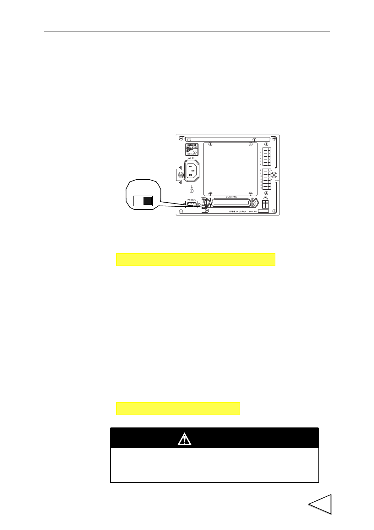
2-2. Rear Panel
1. AC power input connector
Connect the attached AC power cord. The input voltage is 100 ~ 240V AC ( ± 10%), and
the frequency is 50/60Hz.
2. Frame ground (F.G)
This is a grounding terminal. Be sure to ground the FG terminal to prevent electric
shocks and failures caused by static electricity.
3. RS-232C connector
This is an RS-232C connector to send and receive measured data and status information.
The applicable plug is OMRON-manufactured XM2D-0901 (cover: XM2S-0913 <with
inch thread #4-40>) or an equivalent.
(See "4-2. RS-232C Connection" P24, and "18-2. RS-232C Interface" P133.)
11
4. Calibration LOCK switch
This is a LOCK switch to prevent calibrated values from being changed by mistake.
Changing of calibrated values is prohibited when this switch is ON. (See "5-5. LOCK
Release" P34.)
Page 26

2.Name and Function of Each Part
5. Control connector
This is a connector to input and output control signals, operation ch settings, etc. The
applicable plug is DDK-manufactured 57-30500 (accessory) or an equivalent.
(See "4-3. Control Connector Connection" P25.)
6. SI/F terminal
This is a serial interface (SI/F) terminal block to connect a UNIPULSE-manufactured
printer, external display, data converter, etc.
(See "4-1-2. SI/F Connection" P23, and "18-1. SI/F 2-wire Serial Interface" P132)
7. Analog input / output terminals
These are terminals for strain gauge type sensor / displacement sensor inputs and voltage
outputs.
(See "4-1-1. Analog Input / Output Connection" P21.)
8. Optional slot
Up to four optional boards can be mounted.
12
Page 27

3.Screen Configuration and Setting Methods
【Main】
【Mode Setting】
【Special】
【Numerical Value Input】
【Selection】
Each mode key
【Execution】
【Set Value Selection】
【Hold Point Display】
or
* Waveform
Waveform Sampling
Reading
Sampling
* Waveform
Reading
Waveform Editing
* Go to Select Rejected Waveform Reading from the selection screen.
Each setting key
Each
setting
key
3. Screen Configuration and Setting Methods
3-1. Screen Flow Chart
13
Page 28

3.Screen Configuration and Setting Methods
【Waveform Reading 【Hold Point for
【Rejected Waveform 【Rejected Waveform
【Basic Setting】
[Code Setting]
Hold Setting key
【Judgment Setting】
【Hold Setting】
Category key
Waveform Reading】Graph】
Reading Selection】 Reading Graph】
Each
setting
key
【Hold Point for Rejected
Waveform Reading】
14
Page 29

Mode set
PAGE1
CH1 CAL.
CH2 CAL.
Operation Mode
Code set
Wave sampling
Read Wave
Communication
Option set
System
System 2
CH2 CAL.
PAGE1
Axis (P41)
EXC. Volt (P34)
Zero CAL. (P35)
Equiv. CAL. (P36)
Actual CAL. (P37)
Digital Flt. (P38)
Analog Flt. (P38)
PAGE2
Decimal Place (P35)
Unit (P35)
Digital Offset (P38)
Increment (P35)
Read Wave
PAGE1
Read Wave (P92)
Read NG Wave (P96)
NG Wave CLR. (P97)
Control Signal (P99)
Y StartPoint (P97)
Y Scale (P97)
X StartPoint (P98)
X Scale (P98)
Communication
PAGE1
Speed (P133)
Data Length (P134)
Parity (P134)
Terminator (P134)
Communication Mode
(P134)
SI/F Hold Trans. (P134)
SI/F Hold Point (P134)
Main
Operation Mode
PAGE1
Operation Mode (P40)
Sample Rate (P40)
CH1 CAL.
PAGE1
EXC. Volt (P34)
Zero CAL. (P35)
Equiv. CAL. (P36)
Actual CAL. (P37)
Digital Flt. (P38)
Analog FIlt. (P38)
Decimal Place (P35)
PAGE2
Unit (P35)
Digital Offset (P38)
Increment (P35)
Wave Sampling
PAGE1
Wave Call (P82)
Clear (P82)
Sampling (P83)
Edit (P84)
3.Screen Configuration and Setting Methods
3-2. Setting Mode Tree Chart
15
Page 30

3.Screen Configuration and Setting Methods
PAGE2
F-T Output (P120)
Auto Code Up (P107)
Code Up Point (P107)
[Basic]
PAGE1
Parameter Copy (P104)
Select CH (P104)
Wave Start Level (P113)
Wave End Level (P113)
Hold Timer ※ (P105)
Inhibit Timer (P119)
Auto Code Up (P107)
Code Up Point (P107)
System
PAGE1
Protect (P127)
Display Rate (P127)
Backlight (P127)
Contrast (P128)
System 2
PAGE1
All Param. CLR. (P128)
Self Test (P128)
ROM-RAM CHK (P131)
NOVRAM CHK (P131)
PASS WORD (P131)
Code Set (Display items vary depending on the selected Operation Mode.)
Multi-Hold Wave Comp. Hysteresis Wave&Displace Hysteresis 2
[Basic]
PAGE1
Parameter Copy (P104)
Select CH (P104)
Wave Start Level (P113)
Wave End Level (P113)
Hold Timer ※ (P105)
Inhibit Timer (P119)
[Basic]
PAGE1
Parameter Copy (P104)
Select CH (P104)
Lv. Axis Select (P113)
Wave Start Level (P113)
Wave End Level (P113)
Hold Timer ※ (P105)
Inhibit Timer (P119)
Hys. Interval (P119)
F-T Limit (P120)
[Basic]
PAGE1
Parameter Copy (P104)
Select CH (P104)
Lv. Axis Select (P113)
Wave Start Level (P113)
Wave End Level (P113)
Hold Timer ※ (P105)
Inhibit Timer (P119)
F-T Limit (P120)
F-T Output (P120)
[Basic]
PAGE1
Parameter Copy (P104)
Select CH (P104)
Lv. Axis Select (P113)
Wave Start Level (P113)
Wave End Level (P113)
Inhibit Timer (P119)
Hys. Interval (P119)
F-T Limit (P120)
F-T Output (P120)
PAGE2
Auto Code Up (P107)
Code Up Point (P107)
PAGE2
DPM Hold HI (P110)
DPM Hold LO (P110)
[Judgment]
PAGE1
HI-LO Relative (P108)
HI Limit (P109)
LO Limit (P109)
HH/LL Mode (P109)
HI-HI Limit (P109)
LO Limit (P109)
DPM HI-LO Mode (P110)
DPM HI (P110)
DPM LO (P110)
[Judgment]
PAGE1
HI-LO Relative (P108)
HI Limit (P109)
LO Limit (P109)
HH/LL Mode (P109)
HI-HI Limit (P109)
LO Limit (P109)
[Judgment]
PAGE1
HH/LL Mode (P109)
HI-HI Limit (P109)
LO Limit (P109)
U. Area Output (P80)
[Judgment]
PAGE1
HH/LL Mode (P109)
HI-HI Limit (P109)
LO Limit (P109)
DPM HI-LO Mode (P110)
DPM HI (P110)
DPM LO (P110)
DPM Hold HI (P110)
DPM Hold LO (P110)
U. Area Output (P80)
PAGE2
DPM Hold HI (P110)
DPM Hold LO (P110)
[Judgment]
PAGE1
HI-LO Relative (P108)
HI Limit (P109)
LO Limit (P109)
HH/LL Mode (P109)
HI-HI Limit (P109)
LO Limit (P109)
DPM HI-LO Mode (P110)
DPM HI (P110)
DPM LO (P110)
* Only the hold setting includes further setting items.
Setting items vary depending on the hold category
selection. For the items in the hold setting, see "16-2-4.
Hold Setting" P105.
Option Set
PAGE1
PUI
ODN
CCL
* For details, see the
attached Option Manual.
16
Page 31

3.Screen Configuration and Setting Methods
MODE → Code Set → Judgment: PAGE → DPM Hold HI
Main
Mode Setting
3-3. Setting Methods
3-3-1. Specification of Setting Items
In this manual, the method of specifying a setting item is described as follows:
Example:
Specifying the "Displacement Hold High Limit" in the "Hysteresis" mode:
This operation can be performed by the following procedures.
1. Press on the main screen.
2. The mode setting screen appears. Select "Code Set".
17
Page 32
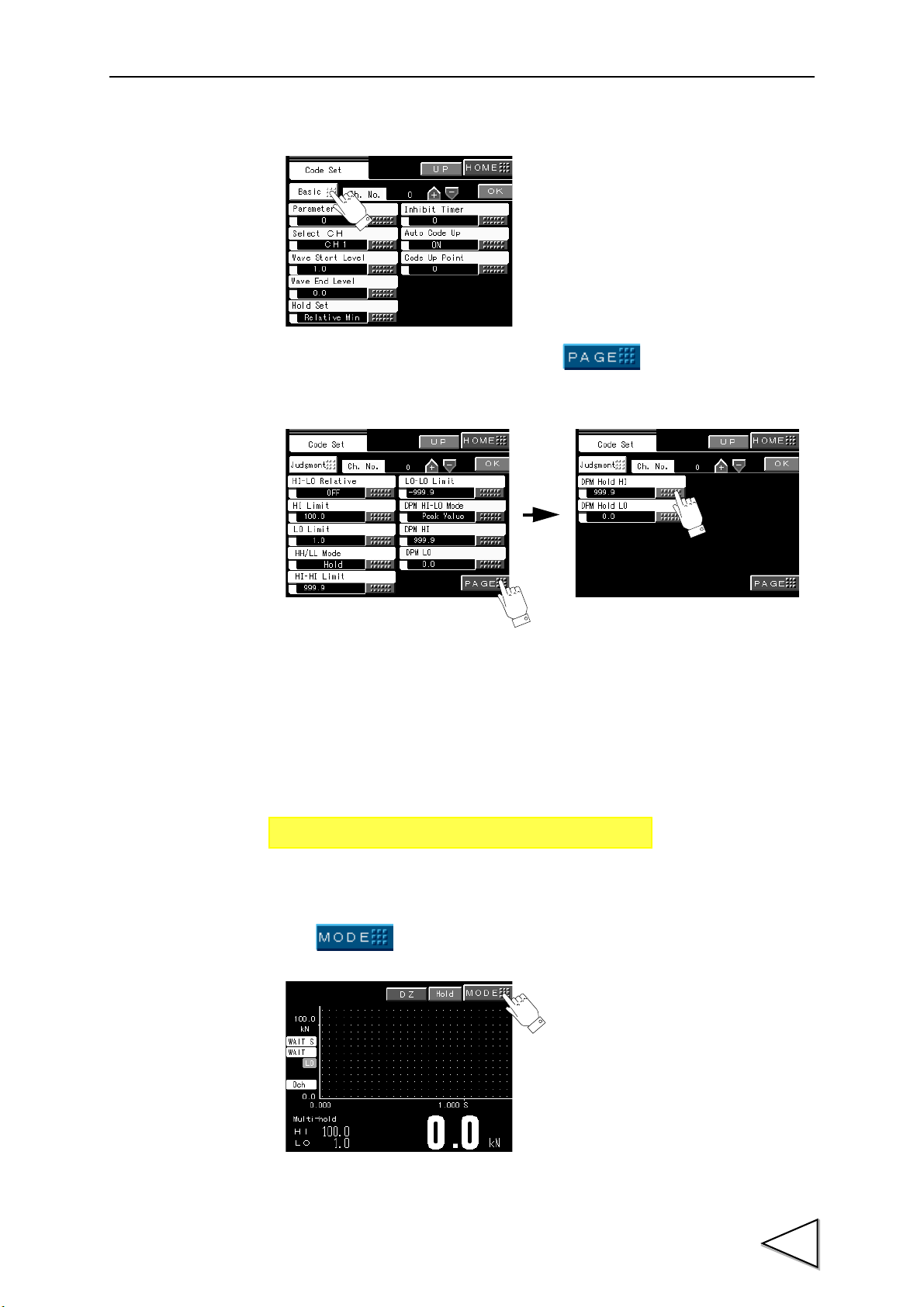
3.Screen Configuration and Setting Methods
Code Setting
Page 1 Page 2
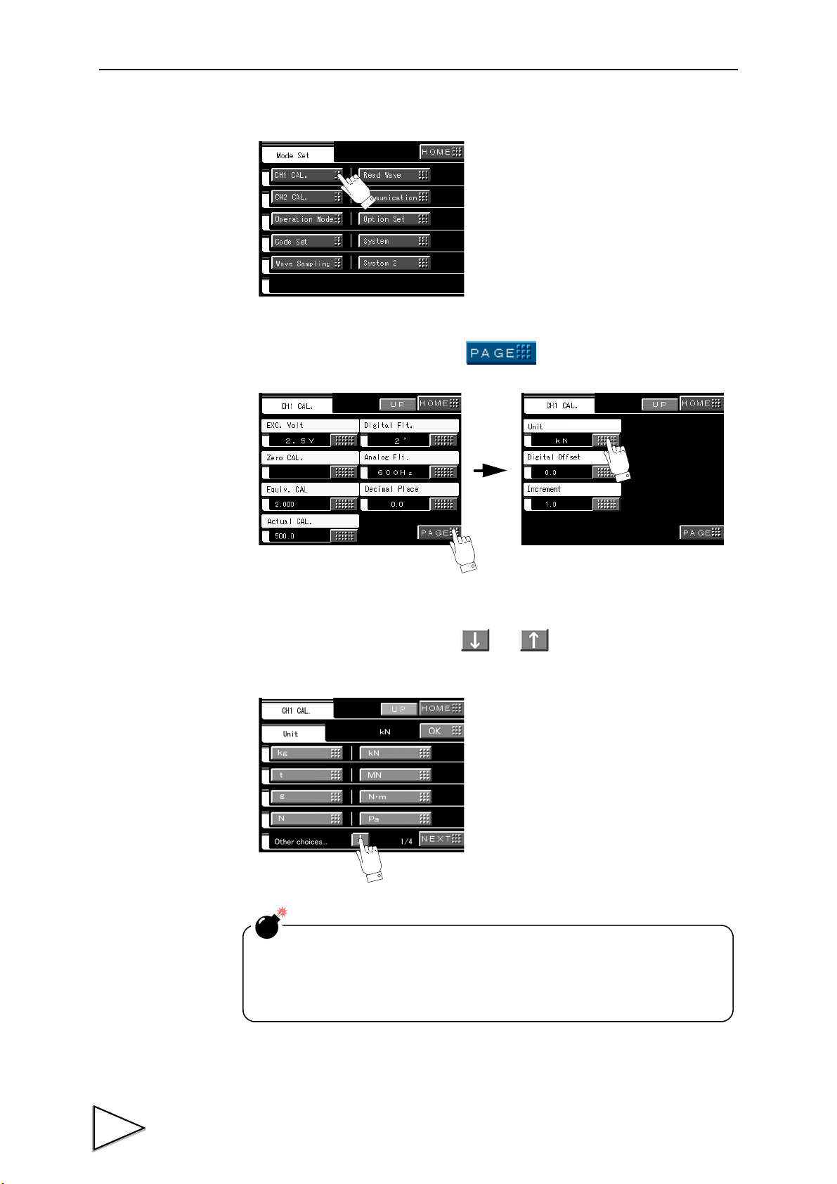
MODE → CAL. → PAGE → Unit
CH1
CH2
Main
3. The basic setting screen in code setting appears. Select "Basic".
4. The judgment setting screen appears. Press and select the setting item
("DPM Hold HI" in this case).
3-3-2. Unit Setting Method
In this manual, the method of setting an item with multiple selections is described as
follows:
Example: Setting a "unit"
This operation can be performed by the following procedures.
1. Press on the main screen.
18
Page 33
3.Screen Configuration and Setting Methods
Mode Set
Channel number selection in code setting is an item to select
internal channel number(s), and is not to change operation ch.
Operation ch is changed by external input.
(See "4-3. Control Connector Connection" P25.)
2. The mode setting screen appears. Select "CH1 CAL.".
3. The CH1 CAL. screen appears. Press , and select "Unit".
4. The unit setting screen appears.
Select a desired item by pressing the and keys.
Check that the desired description is displayed at the top, and press OK for entry.
19
Page 34
4.Methods of Connection
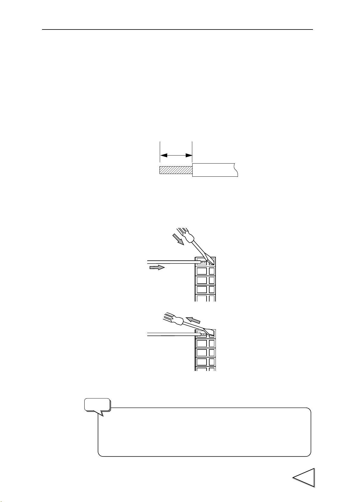
5 ~ 6mm
・ Wires connectable to the cage clamp type terminal block are
0.2 ~ 2.5mm2.
・ Do not attach crimp contacts to the ends of wires, or solder them.
・ When connecting two or more wires, twist them beforehand.
Request
4. Methods of Connection
4-1. Connection to the Cage Clamp Type Terminal Block
Connect to the cage clamp type terminal block by using the attached mini-screwdriver.
1. Peel the sheath of the wire to be connected 5 ~ 6mm, and twist the end to such an
extent so that it will not become loose.
2. Insert the screwdriver firmly into the hole on the right-hand side while pushing it up
slightly.
3. Insert the wire into the hole on the left-hand side so as not to loosen the end.
4. Withdraw the screwdriver.
5. Lightly pull the wire to check that it is clamped securely.
20
Page 35

4.Methods of Connection
The CH1 and CH2 input sensor specifications (strain gauge/current/
voltage) are factory-shipped settings. For changing the settings,
contact us since modifications are required. CH1 corresponds to a
strain gauge, and CH2 corresponds to voltage as a standard.
Request
4-1-1. Analog Input / Output Connection
4-1-1-1. Analog Input / Output Terminal Pin Assignments
1 FG : Frame ground. Terminal to connect the shield of sensor
connection cabling.
2 + EXC : Terminal to connect a strain gauge type sensor.
3 - SIG : Terminal to connect a strain gauge type sensor or displacement
sensor.
4 - EXC : Terminal to connect a strain gauge type sensor.
5 + SIG : Terminal to connect a strain gauge type sensor or displacement
sensor.
6 V-OUT : Terminal that outputs voltage proportional to sensor input.
The voltage output is approx. 2V per 1mV/V sensor input, and
the load resistance is 5kΩ or more
7 N.C
* 1 ~ 6 are input / output terminals for CH1.
8 V-OUT : Terminal that outputs voltage proportional to sensor input.
The voltage output is approx. 2V per 1mV/V sensor input, and
the load resistance is 5kΩ or more.
9 GND : GND terminal for the V-OUT terminal. (Common to pin 6 and
pin 8.)
10 + EXC : Terminal to connect a strain gauge type sensor.
11 - SIG : Terminal to connect a strain gauge type sensor or displacement
sensor.
12 - EXC : Terminal to connect a strain gauge type sensor.
13 + SIG : Terminal to connect a strain gauge type sensor or displacement
sensor.
14 FG : Frame ground. Terminal to connect the shield of sensor
connection cabling.
* 8 ~ 14 are input / output terminals for CH2. (Pin 9 is common to CH1 and CH2.)
21
Page 36

4-1-1-2. Strain Gauge Sensor Connection
・ For connecting a sensor, be sure to use shielded lines, and separate
wiring from lines with heavy noise (such as wiring of power equipment
and wiring of digital equipment) and AC lines.
・ The analog GND in the F395 is grounded to F.G. Also, when voltage/
current input is specified, the -SIG terminal is at about the same level
as the analog GND. (See "20. Block Diagram" P152.) Carry out wiring
so that unnecessary current will not flow.
Request
+ EXC
- EXC
+ SIG
- SIG
F. G
+ IN
- OUT
- IN
+ OUT
F395
+ EXC
- EXC
+ SIG
- SIG
F. G
+ IN
- OUT
- IN
+ OU T
+ S
- S
F395
Before connecting a sensor, set the excitation voltage, turn off the power, and perform
the following connection. (See "5-6. Excitation Voltage" P34.)
・4-wire sensor
4.Methods of Connection
・ 6-wire sensor
For connecting a 6-wire strain gauge type sensor, short-circuit +EXC and +S, and -EXC
and -S.
22
Page 37

4.Methods of Connection
+ SIG
- SIG
Voltage / current
+
-
F395
Output
type sensor
Within ± 5V/ ± 20mA
V-O UT
GND
External equipment
Load resistance
5kΩ or more
+
-
F395
No displacement sensor (for X-axis measurement) can be
connected when the PUI option is mounted.
Converter
Display
Printer
SI/F
F395
<Example of connection>
4-1-1-3. Voltage / Current Type Sensor Connection
Contact type, overcurrent type, laser type, and other voltage / current type sensors of up
to ± 5V / ± 20mA can be connected. (The analog input option is a factory-shipped
setting.)
4-1-1-4. Voltage Output (V-OUT) Connection
The relationship between sensor type and output voltage is as follows:
Strain gauge 1mV/V ............ Approx. 2.0V
Voltage 5V .............Approx. 5.6V
Current 20mA .............Approx. 5.2V
4-1-2. SI/F Connection
This is a 2-wire serial interface to connect a UNIPULSE-manufactured printer, external
display, etc.
Up to three nonpolarized external devices can be connected. Use parallel two-core
cables, cabtyre cables, and the like for wiring.
23
Page 38
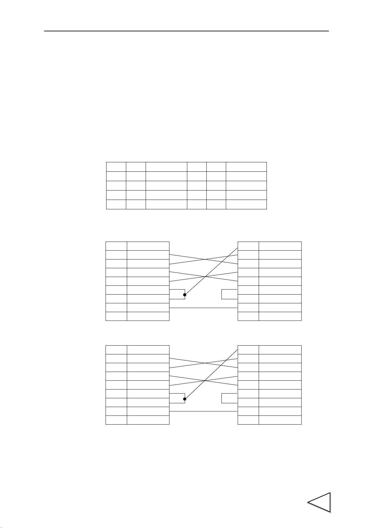
4-2. RS-232C Connection
1
2
RXD
3
TXD
4
DTR
6
DSR
7
RTS
8
CTS
5
GND
9
1
CD
2
RXD
3
TXD
4
DTR
6
DSR
7
RTS
8
CTS
5
GND
9
FG
PC (9-pin)
F395
1
2
RXD
3
TXD
4
DTR
6
DSR
7
RTS
8
CTS
5
GND
9
8
CD
3
RXD
2
TXD
20
DTR
6
DSR
4
RTS
5
CTS
7
GND
1
FG
PC (25-pin)
F395
Cross type cabling
Cross type cabling
4-2-1. RS-232C Connector
The RS-232C connector is a D-SUB 9-pin connector. The applicable plug is OMRON-
manufactured XM2D-0901 (cover: XM2S-0913 <with inch thread #4-40>) or an
equivalent.
4-2-2. Connector Pin Assignments
Applicable plug: D-SUB 9-pin connector
* OMRON-manufactured XM2D-0901 (cover: XM2S-0913 <with inch thread #4-40>), etc.
4.Methods of Connection
16IN
2IN
3OUT
4OUT
5*
RXD
TXD
DTR
GND
7OUT
8IN
9
DSR
RTS
CTS
4-2-3. Example of Cabling
The above connection diagram shows cabling (as an example) when the PC is DTE (data
24
terminal equipment). If the other end of the connection is DCE (data circuit-terminating
equipment) such as a modem, use straight type cabling. Also, recheck the connector
shape and signal lines (pin assignments) of the equipment you use before preparation of
cabling.
Page 39
4.Methods of Connection
4-3. Control Connector Connection
The control connector is a connector to input signals to allow the F395 to function, and
to output control signals from the F395 to external equipment.
The applicable plug is DDK-manufactured 57-30500 (accessory) or an equivalent.
4-3-1. Connector Pin Assignments
1*COM 26*COM
2 IN Display after measurement 27 IN D/Z
3 IN Capture start by external signal 28 IN T/H
4 IN Operation by waveform
termination level
5 IN Prohibit touch panel 30 IN START
6 IN Displacement hold cancel 31 IN STOP
7 IN Backlight ON 32 IN HOLD1
8 IN Select HH/LL 33 IN HOLD2
9 IN Reset auto code up 34 IN HOLD3
10 * COM 35 * COM
11 IN CODE1 36 IN CODE16
12 IN CODE2 37 IN STROBE
13 IN CODE4 38 IN Select output
14 IN CODE8 39 IN N.C
15 * COM 40 * COM
16 * COM 41 * COM
17 OUT LO1 42 OUT OK displacement 1
18 OUT OK1 43 OUT HI displacement 1
19 OUT HI 1 44 OUT LO displacement 2
20 OUT HH/LL 45 OUT OK displacement 2
21 OUT LO 2 46 OUT HI displacement 2
22 OUT OK 2 47 OUT COMPLETE
23 OUT HI 2 48 OUT WARNING
24 OUT LO displacement 1 49 OUT Hysteresis return
25 * COM 50 * COM
29 IN H/M
4-3-2. Input and Output Signals
Input signals
・Display after measurement:
A measured value at the completion of measurement is held when this signal is ON,
and the holding is cancelled when OFF in the Waveform Comparison / Waveform
and Displacement Comparison mode.
(See "13-9. Display After Measurement" P81.)
[Holding of the value is cancelled when the next sampling starts.]
25
Page 40

4.Methods of Connection
・Capture start by external signal:
Sampling is started by the rising edge of the START input irrespective of the
Waveform Start Level when this signal is ON.
(See "9. Method of Starting Measurement" P43
・ Waveform termination level operation:
Sampling is stopped by the Waveform Termination Level when this signal is ON.
(See "16-2-9. Level Axis Select / Waveform Start Level / Waveform Termination
Level / Hold Start Level" P113.)
・Prohibit touch panel:
The touch panel is prohibited when this signal is ON.
・Displacement hold cancel:
The displacement peak value for Displacement High/Low Limit Comparison is
cancelled when this signal is ON. (See "16-2-8. Displacement High-low Mode /
Displacement High Limit / Displacement Low Limit / Displacement Hold High Limit
/ Displacement Hold Low Limit" P110.)
・Backlight ON:
The backlight is lit when this signal is ON. If it is kept ON, the backlight will not go
out.
・Select HH/LL:
Selects operation of HH/LL output (pin 20).
When this signal is OFF: Result of judgment on the currently set operation ch.
When this signal is ON: Accumulated
*1
result of judgment on the pre-switching
operation ch.
・ Reset auto code up:
The Auto Code Up mode is canceled by turning this signal ON after completion of
sampling as follows:
- The operation ch is reset.
- The reference values for High-Low Relative Comparison are cleared.
- Hold reset by T/H and H/M becomes executable.
・ D/Z:
Digital Zero is performed by the ON edge. (See"6-4. Digital Zero" P39.)
・T/H, H/M:
Directs the timing of hold operation. (See "10-3. Hold Functions" P48.)
・ START, STOP:
Directs waveform drawing operation.
(See "9. Method of Starting Measurement" P43)
・HOLD1 ~ 3:
Pulse input 1 ~ 3 for Pulse Hold / Hysteresis 2.
(See "10-3-10. Pulse Hold" P62, and "12. Hysteresis 2" P65.)
Accumulated
*1
: When multiple operation channels are switched, once HI2 / LO2 results,
HI2 / LO2 remains ON, and OK2 turns OFF.
26
Page 41
4.Methods of Connection
A level edge is generated when the input signal (indicated value)
crosses over the Waveform Start Level after the START signal is input.
It is cleared by starting sampling or inputting the STOP signal. (See "9.
Method of Starting Measurement" P43.)
・CODE1 ~ 16:
・STROBE:
・ Select output:
Specifies operation ch for Hold mode, High/Low Limit, Comparison Waveform, etc.
(See "10-2. Setting and Operating Method" P47, "11-2. Setting and Operating
Method" P64, "12-2. Setting and Operating Method" P65, and "13-2. Setting and
Operating Method" P68.)
Changing of operation ch by changing CODE 1 ~ 16 is prohibited when this signal is
ON. (Previous operation ch is maintained.) Use to prevent chattering when changing
operation ch.
Output pin 44 ~ 46 (LO/OK/HI displacement 2) operate when this signal is ON.
- Pin 44/45 "Status" output
Status Pin 44 Pin 45
WAITS / STOP 0 0
WA IT 2 1 0
WA I T L 0 1
SAMP / COPY 1 1
(
For logic, see "4-3-4. Equivalent Circuit (Output)" P30. )
- Pin 46 "Level Edge" output (Present when this signal is ON. Use for level
edge clear, etc.)
When this signal is OFF, output pin 44 ~ 46 result in the operation of LO/OK/HI
displacement 2.
Judgment output signals
The results of High/Low Limit Judgment in each Operation Mode are output.
・LO1, OK1, HI1 : 1) When the Multi-Hold / Hysteresis mode is used.
Outputs the results of judgment of the load with respect to the
high limit / low limit.
2)When the Waveform Comparison / Waveform and Displace-
ment Comparison mode is used.
Outputs the results of judgment of the load with respect to the
high and low limit waveforms.
3) When the Hysteresis 2 mode is used.
Outputs the results of judgment of the load with respect to the
high limit / low limit, and the results of judgment of the
difference between go and return with respect to the hi-hi
limit / lo-lo limit.
27
Page 42

4.Methods of Connection
・HH/LL :1) When the Multi-Hold / Hysteresis mode is used.
Outputs the results of judgment of the load with respect to the
hi-hi limit / lo-lo limit.
2) When the Waveform Comparison / Waveform and
Displacement Comparison mode is used.
Not used. (The output remains OFF.)
・LO displacement 1,: 1) When the Hysteresis / Hysteresis 2 / Waveform and
OK displacement 1, Displacement Comparison mode is used.
HI displacement 1 Outputs the results of judgment of the displacement with
respect to the displacement high limit / displacement low
limit / displacement hold high limit /displacement hold low
limit.
2) When the Multi-Hold / Waveform Comparison mode is used.
Not used. (OK displacement 1 turns ON.)
・LO2, OK2, HI2 : 1) When the Multi-Hold / Hysteresis mode is used.
Outputs the accumulated
*1
results of judgment of LO1, OK1
and HI1 on the previous operation channel at switch-time.
Returns to OK2 when the START signal is turned ON.
2) When the Hysteresis 2 mode is used.
Outputs the accumulated
*1
results of judgment of LO1, OK1
and HI1 with the timing of inputting HOLD1, HOLD2 and
HOLD3.
Outputs the accumulated
*1
results of judgment of LO1, OK1
and HI1 with the timing of judging the difference between go
and return.
Returns to OK2 when the START signal is turned ON.
3) When the Waveform Comparison / Waveform and
Displacement Comparison mode is used.
Outputs the results of judgment of the load with respect to the
hi-hi limit / lo-lo limit.
・LO displacement 2,: 1) When the Hysteresis mode is used.
OK displacement 2, Outputs the accumulated
*1
results of judgment of
HI displacement 2 LO displacement 1, OK displacement 1 and
HI displacement 1 on the previous operation channel at
switch-time.
Returns to OK displacement 2 when the START signal is
turned ON.
2) When the Hysteresis 2 mode is used.
Outputs the accumulated
*1
results of judgment of LO
displacement 1, OK displacement 1 and HI displacement 1
with the timing of inputting HOLD1, HOLD2 and HOLD3.
Returns to OK2 when the START signal is turned ON.
28
Page 43
4.Methods of Connection
COMPLETE may be output earlier than each judgment output due to
signal delay in wiring, etc. Do not take in judgment at the ON edge of
the COMPLETE signal.
・COMPLETE :This signal is output upon judgment or hold. Read each output
3) When the Multi-Hold / Waveform Comparison / Waveform
and Displacement Comparison mode is used.
Not used. (OK displacement 2 turns ON.)
4) When the output selection is ON, LO displacement 2, OK
displacement 2 and HI displacement 2 are changed to
“Status” and “Level Edge” outputs. (For details, see “Select
output” P.27.)
signal after confirming that this signal is ON.
(For output timing, see "10-3. Hold Functions" P48, and "13-6.
Timing in the Waveform Comparison / Waveform and
Displacement Comparison Mode" P76.)
・WA R N IN G :
This signal is output when displacement input is used and sampling is thinned out.
(See "13-5. Waveform and Displacement Comparison Mode" P74.)
・ Hysteresis return:
This signal is turned ON when return waveform sampling starts, and is turned OFF
upon completion in the Hysteresis / Hysteresis 2 mode. This signal is turned OFF in
go waveform sampling and in other modes. (See "11-2. Setting and Operating
Method" P64.)
Accumulated
*1
: When multiple operation channels are switched, once HI2 / LO2 results,
HI2 / LO2 remains ON, and OK2 turns OFF.
29
Page 44

4-3-3. Equivalent Circuit (Input)
Inside
IC=
COM
Push swich Toggle swich Relay contact Transistor
+12V
IN
IN
F395
Open: OFF
Short circuit: ON
・ No external voltage should be applied to the signal input circuit.
・ External elements should pass Ic=10mA or more.
・ Leaks of external elements should be 100μA or less.
・The external input circuit is minus (-) common. A circuit of source
type cannot be connected.
6mA
Approx.
TTL open collector output
(ON when IN is
‘
H ’)
Vcc
+12V
COM
F395
・ For the relay driving power supply (Vext), prepare an external power
supply.
・ Do not short-circuit any load (relay coil, etc.); otherwise the output
transistor will be damaged.
・ Connect surge absorbers or spark killers to the relay circuit (coil side and
contact side) as shown in the illustration to minimize surge voltage.
Ve x t
Transistor state
Output data Tr
0OFF
1ON
Vceo=30V(max)
Ic=120mA(max)
Inside
Relay
Spark killer
Load
Spark killer
Load
Varistor
AC power
supply
DC power
supply
Vcc
+12V
The signal input circuit inputs a signal by short-circuiting or opening the input terminal
and COM terminal. Short-circuiting is performed by contact (relay, switch, etc.) or non-
contact (transistor, TTL open collector output, etc.)
4.Methods of Connection
4-3-4. Equivalent Circuit (Output)
The signal output circuit produces transistor open collector output.
30
Page 45

5.Methods of Calibration
+
Rated output value mV/V, V, mA
Indicated value
Strain gauge type sensor
Displacement sensor
In either case of Equivalent Input Calibration and Actual Load Calibration,
set the Excitation Voltage before connecting the strain gauge type sensor.
(See "5-6. Excitation Voltage" P34.)
Request
Strain gauge type sensor
Displacement sensor
Actual load
Displacement
Actual load value (displacement)
5. Methods of Calibration
5-1. What is Calibration?
Operation of matching the F395 and sensor is called "Calibration".
For the F395, there are two methods of calibration as follows:
Equivalent input calibration
By this method, calibration is performed by simply inputting the rated output value (mV/
V, V, mA) of the sensor and the indicated value by keypad without using an Actual Load.
Calibration can easily be performed even if an actual load is not prepared.
Actual load calibration
By this method, calibration is performed by giving an actual load (displacement) to the
sensor and inputting the actual load (displacement) by keypad. Accurate calibration with
few errors can be performed.
5-2. CH1 Input Calibration and CH2 Input Calibration
Perform calibration with respect to each of analog input CH1 and CH2. CH2 may be set
for measuring the X-axis (displacement input). (The axis in current use is displayed in
the Axis setting under CH2 Input Calibration.)
31
Page 46

5-3. Equivalent Input Calibration Procedures
Decimal place setting
Set value protection cancel
Unit setting
Set value protection
Zero calibration
LOCK switch OFF
Excitation voltage setting
LOCK switch ON
Equivalent input calibration
Increment setting
Perform equivalent input calibration of the sensor as follows:
Turn off the LOCK switch on the rear panel to unprotect
calibration.
Set the "Set Value Protection" setting to unprotect
calibration.
Select the "Excitation Voltage" from 2.5V/10V.
(Set 2.5V when the input specification is voltage / current.)
Turn off the power, and connect the sensor.
5.Methods of Calibration
Set the "Unit" to be used.
Set the "Decimal Place".
Set the minimum value of the digital changes.
Set the initial zero point.
Set the rated output value of the sensor.
Protect calibration to prevent misoperation.
Turn on the LOCK switch to protect calibration to prevent
misoperation.
32
Page 47

5.Methods of Calibration
Decimal place setting
Increment setting
Set value protection cancel
Unit setting
Set value protection
Zero calibration
LOCK switch OFF
Excitation voltage setting
LOCK switch ON
Actual load calibration
5-4. Actual Load Calibration Procedures
Perform Actual load calibration of the sensor as follows:
Turn off the LOCK switch on the rear panel to unprotect
calibration.
Set the "Set Value Protection" setting to unprotect
calibration.
Select the "Excitation Voltage" from 2.5V/10V.
(Set 2.5V when the input specification is voltage / current.)
Turn off the power, and connect the sensor.
Set the "Unit" to be used.
Set the "Decimal Place".
Set the minimum value of the digital changes.
Set the initial zero point.
Set the span (gain) point of the sensor.
Protect calibration to prevent misoperation.
Turn on the LOCK switch to protect calibration to prevent
misoperation.
33
Page 48
5-5. LOCK Release
LOCK
OFF
MODE → System → Protect → All Unprotect
MODE → CAL. → EXC. Volt
CH1
CH2
The excitation voltage of the F395 is 2.5V/10V. If the maximum
excitation voltage of the sensor is less than 2.5V/10V, heating or
breakage may result.
CAUTION
Calibrated values and set values can be locked to prevent a change due to misoperation.
There are two types of locks: a software lock to be operated from the screen, and a
hardware lock by the switch on the rear panel. For performing calibration, release both
locks.
1. Turn off the LOCK switch on the rear panel. (Hardware lock)
5.Methods of Calibration
2. Set the "Set Value Protection" setting to "All Unprotect". (Software lock)
Now, the locks are released. Upon completion of calibration, hardware lock and software
lock again to prevent misoperation.
5-6. Excitation Voltage
Set the voltage value to be applied to the bridge of the strain gauge sensor. Select as large
a value as possible within the range not exceeding the maximum excitation voltage of the
sensor.
Setting item: 2.5V / 10V
34
Page 49

5.Methods of Calibration
MODE → CAL. → PAGE → Unit
CH1
CH2
MODE → CAL. → PAGE → Increment
CH1
CH2
MODE → CAL.
CH1
CH2
→ Decimal Place
→ PAGE → Decimal Place
MODE → CAL. → Zero CAL.
CH1
CH2
5-7. Unit
Set the measuring unit. Select from the following.
5-8. Increment
Set the minimum value of digital changes.
Setting item: kg / t / g / N / kN / MN / N・m / Pa / kPa / MPa / bar / N/m
/ μm / rad / deg / lb / oz / dyne / psig / ftlb / inlb / inoz / ft / in / None
Setting range: 1 ~ 100 (Not including the decimal point.)
2
/ mm / cm
5-9. Decimal Place
Set the decimal place.
Setting item: 0 / 0.0 / 0.00 / 0.000
5-10. Zero Calibration
Set the initial zero point.
1. Bring the sensor into a zero condition (no-load condition).
2. Press OK under Zero Calibration.
3. For error display, see "19. Error Messages" P150.
35
Page 50

5-11. Equivalent Input Calibration
MODE → CAL. → Equiv. CAL.
CH1
CH2
The strain gauge type sensor comes with a data sheet upon purchase.
Capacity ................... Load/displacement (unit: kN, Mpa, etc.)
Rated Output............ Voltage (unit: mV/V)
Non-Linearity, Hysterisis,Input Resistance,Output Resistance,
Zero Balance, etc.
Values necessary for equivalent input calibration are the capacity and
rated output. Input these two values to the F395.
Set the rated output value of the sensor.
1. Select the "Equivalent Input Calibration" item.
2. Input set values as follows:
("i.- iii." depend on the analog input specifications (factory-shipped settings).)
i. Strain gauge type sensor
Sensor Output mV/V? .. Setting range: -9.999 ~ -0.100, 0.100 ~9.999
Load? ............................ Setting range: 100 ~ 9999 (Not including the decimal point.)
ii. Voltage output sensor
Sensor Output V?.......... Setting range: -9.999 ~ -0.100, 0.100 ~ 9.999
Load? ............................ Setting range: 100 ~ 9999 (Not including the decimal point.)
5.Methods of Calibration
iii. Current output sensor
Sensor Output mA? ...... Setting range: -99.99 ~ -1.00, 1.00 ~ 99.99
Load? ............................ Setting range:100 ~ 9999 (Not including the decimal point.)
3. For error display, see "19. Error Messages" P150.
36
Page 51

5.Methods of Calibration
MODE → CAL. → Actual CAL.
CH1
CH2
Calibration cannot be performed with the same input value
as zero calibration.
The full scale value of displacement is determined by the value
input for the "Load?" item of Equivalent Input Calibration or Actual
Load Calibration in the Hysteresis / Hysteresis 2 / Waveform and
Displacement Comparison mode. The relationship between the
input value (X-axis calibrated value) and full scale value is as
follows:
Input value
(X-axis calibrated value)
Full scale value
1 ~ 2047
2047
2048 ~ 4095
4096
4096 ~ 8191
8188
8192 ~ 9999
16376
5-12. Actual Load Calibration
Set the span (gain) point of the sensor.
1. Select the "Actual Load Calibration" item.
2. Set in accordance with the display.
Load?.... Setting range: -9999 ~ -100, 100 ~ 9999 (Not including the decimal point.)
3. For error display, see "19. Error Messages" P150.
37
Page 52

6.Settings and Operations Relating to Indicated Values
MODE → CAL. → Digital Flt.
CH1
CH2
MODE → CAL. → Analog Flt.
CH1
CH2
MODE → CAL. → PAGE → Digital Offset
CH1
CH2
If Zero Calibration / DZ is performed with the digital offset set
at "-100," the displayed indicated value becomes "100."
6. Settings and Operations Relating to Indicated Values
6-1. Digital Filter
A/D-converted data is moving-averaged to reduce unsteadiness of indicated values by
this function. The number of times of moving average can be selected from the
following. With an increasing number of times of moving average, the display stabilizes
but the response becomes slow.
Setting item: None / 2’ / 4’ / 8’ / 16 ’/ 32’
6-2. Analog Filter
This is a low-pass filter to cancel unnecessary noise components by filtering input
signals from the sensor. The cutoff frequency of the low-pass filter can be selected from
the following. With increasing cutoff frequency, the response becomes fast but noise
components may be displayed in a waveform.
Setting item: 10Hz / 50Hz / 200Hz / 600Hz
6-3. Digital Offset
The digital reference point (zero point of indicated values) is offset by this function. The
value set here is subtracted from the actual indicated value (added if the sign is negative)
for display.
(Displayed indicated value) = (Actual indicated value) - (Digital offset set value)
Setting range: -9999 ~ +9999 (Not including the decimal point.)
38
Page 53

6.Settings and Operations Relating to Indicated Values
Digital Zero can be operated only when the Set Value Protection
setting is either "CAL. Protect" or "All Protect," or the LOCK switch on
the rear panel is ON.
Also, the displacement input value cannot be zeroed by the above
methods.
It is automatically zeroed when sampling starts if the Level Axis
Select setting (See "16-2-9. Level Axis Select / Waveform Start Level
/ Waveform Termination Level / Hold Start Level" P113.) is "Y-axis" in
the Hysteresis / Hysteresis 2 / Waveform and Displacement
Comparison mode with the above condition met. (See "13-5.
Waveform and Displacement Comparison Mode" P74.)
6-4. Digital Zero
Indicated values are zeroed forcedly by this function. There are two methods as follows:
1. Press the DZ key on the main screen.
2. Short-circuit D/Z and COM of the control connector.
39
Page 54

7.Measurement Operation Functional Settings
MODE → Operation Mode → Operation Mode
MODE → Operation Mode → Sample Rate
7. Measurement Operation Functional Settings
7-1. Operation Mode
Set the Operation Mode according to the working conditions from the following.
Setting item: Multi-Hold / Wave Comp. / Hysteresis / Wave&Displace / Hysteresis2
When the mode is changed to Hysteresis / Waveform and Displacement Comparison /
Hysteresis 2, if the sampling rate has been set at 4kHz, the sampling rate is automatically
changed to 2kHz. At the same time, the buzzer beeps.
7-2. Sampling Rate
Select the sensor signal reading speed from the following.
Setting item: 4 kHz / 2 kHz / 1 kHz / 500 Hz / 200 Hz / 100 Hz
(4kHz cannot be set in the Hysteresis / Waveform and Displacement Comparison /
Hysteresis 2 mode.)
The relationship between the sampling rate (frequency) and reading speed is as follows:
Sampling rate Reading speed
4kHz 4000 times/sec.
2kHz 2000 times/sec.
1kHz 1000 times/sec.
500Hz 500 times/sec.
200Hz 200 times/sec.
100Hz 100 times/sec.
40
Page 55
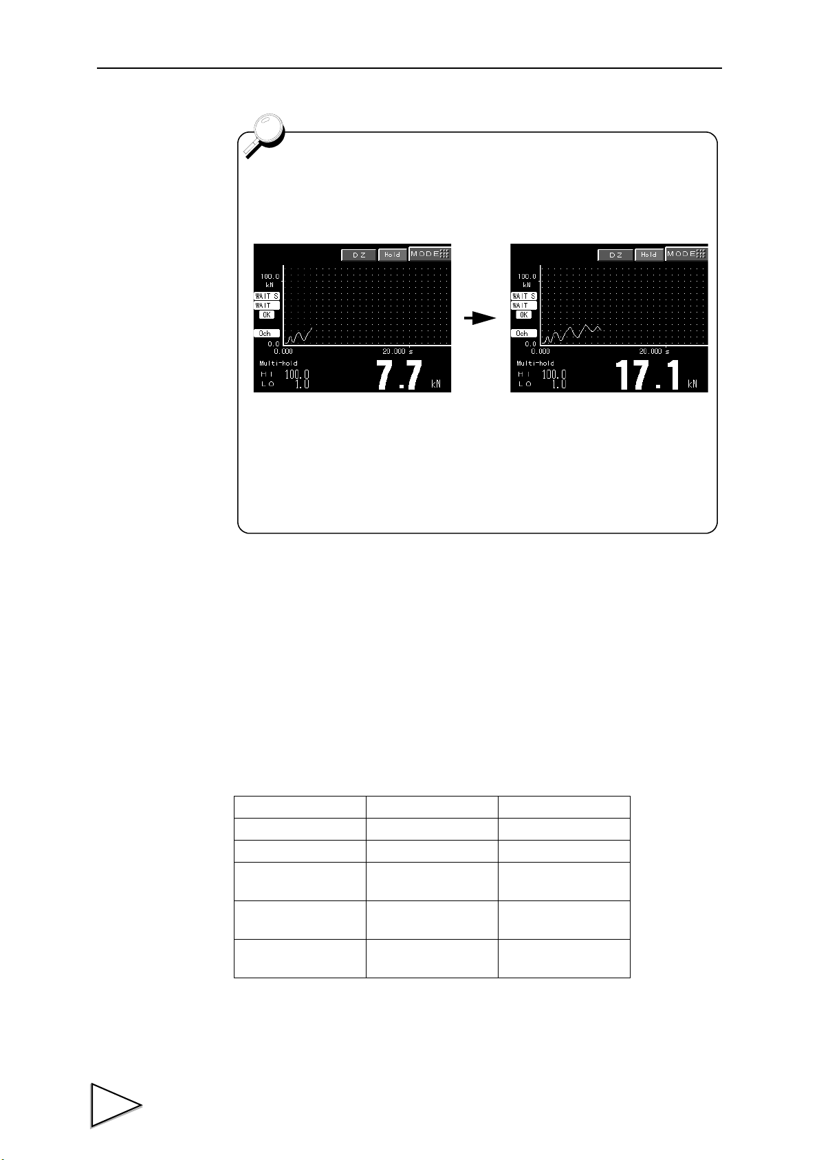
7.Measurement Operation Functional Settings
About advance waveform display
When the operation mode is Multi-Hold or Waveform Comparison, a
waveform is displayed gradually without waiting for completion of takingin of the waveform by setting the sampling rate to 100Hz or 200Hz.
The display rate changes according to the X-axis scaling.
This function simply handles waveform data, and hold points are
displayed after measurement.
The previous waveform is dismissed when the next measurement starts.
(The waveform can be read.)
Advance display is not carried out unless the main screen is displayed
when a measurement starts.
7-3. Sampling Reset
If CH1/CH2 input calibration, Operation Mode, or PUI setting (optionally mounted) is
changed, the F395 stops sampling, and moves to a sampling waiting condition.
At this time, the results of hold / comparison are also reset.
7-4. X/Y-axis Setting by Operation Mode and Input CH
Analog input CH1/CH2 functions as X/Y-axis analog input depending on the Operation
Mode.
Operation Mode Y-axis X-axis
Multi-Hold CH1/CH2 Time
Wave Comp CH1/CH2 Time
Hysteresis CH1
Wave&Displace CH1
Hysteresis2 CH1
CH2
(displacement input)
CH2
(displacement input)
CH2
(displacement input)
* Set CH1/CH2 under Select Analog CH. (See "16-2-3. Select Analog CH" P104.)
41
The current X/Y-axis setting of CH2 can be confirmed by the Axis setting on the CH2
Input Calibration screen. (The setting cannot be changed by this item.)
Page 56
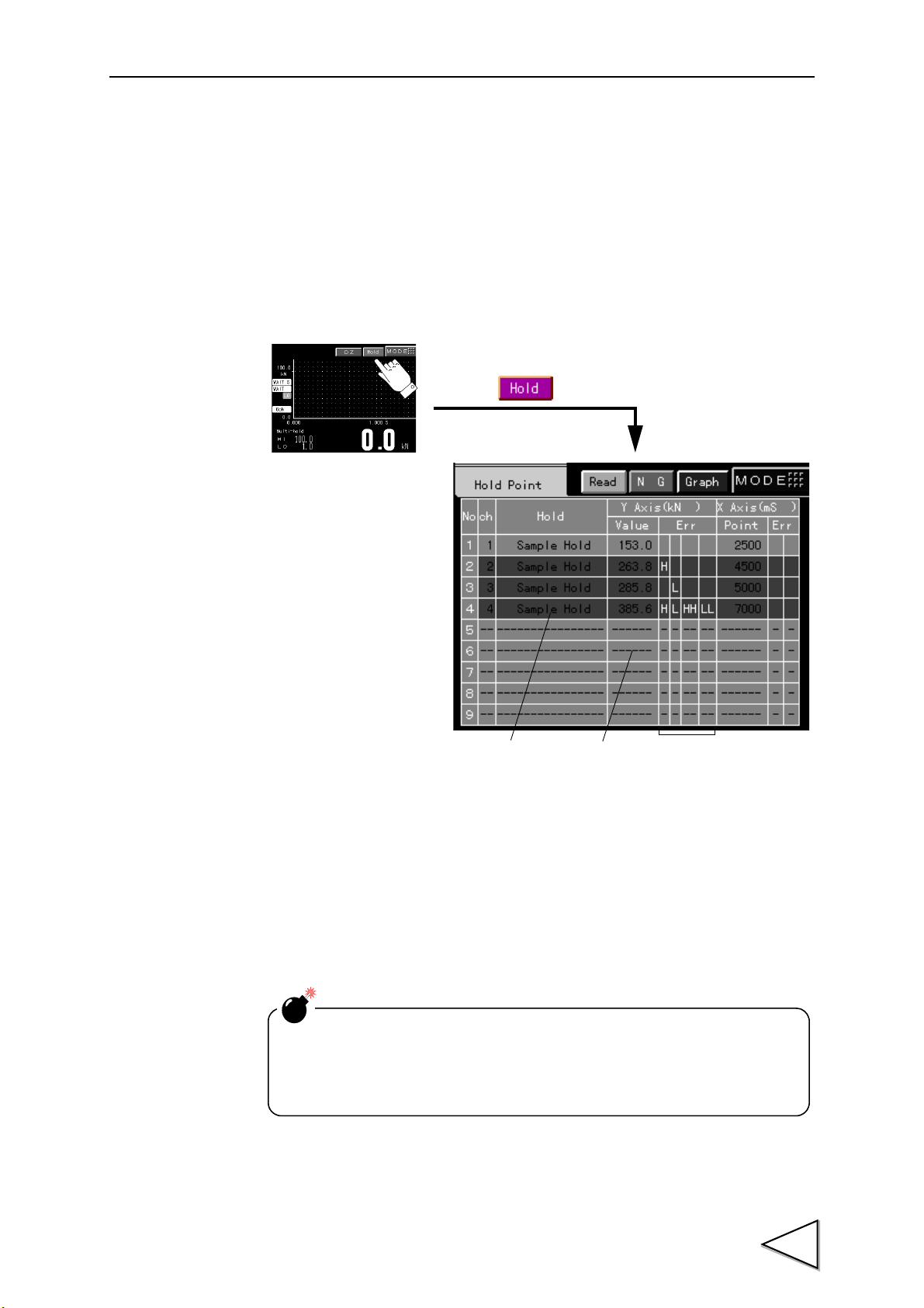
8. Hold Point Display Screen
21
Press the key.
3
[Hold Point Display Screen]
[Graph Screen]
Since the display is always updated, read specific results of
measurement in detail from the Waveform Reading screen. (See "15-1.
Waveform Reading" P92.) (The Waveform Reading screen is not
updated to the latest results of measurement.)
Up to 9 results of measurement can be confirmed on the hold point display screen. Since
the display is always updated every time a measurement is made in order to display the
latest results of measurement, use the display by switching from the graph screen
according to the measuring conditions.
8.Hold Point Display Screen
1 .......... If any result is an error, the whole column becomes red.
2 .......... If there is no result, "----" is displayed
3 .......... The results of comparison are displayed. (H, L, HH, or LL is displayed. Blank
when OK.)
42
Page 57

9.Method of Starting Measurement
START
STOP
Rear
Strain gauge type sensor
t
+
START
STOP
WAIT L SAMPLE STOP
WAIT 2
OFF
ON
OFF
ON
Waveform
start level
Trigger point where
the level is crossed
Start of waveform capturing
Start
End of sampling
Status display
Waveform capturing
period
9. Method of Starting Measurement
The following conditions should be met for the F395 to display input signals from the
strain gauge sensor as a waveform on the screen and start measurement. (For details of
input and output signals, see "4-3-2. Input and Output Signals" P25.)
i. The START signal turns from ON to OFF.
ii. The input signal crosses over the Waveform Start Level.
(Only "i." when the signal "Capture start by external signal" is ON.)
Waveform drawing ends when the STOP signal turns ON, or when 2048-point sampling
is exceeded, or when the input signal crosses over the Waveform Termination Level with
the signal "Waveform termination level operation" ON.
The relationship between the input signal, START / STOP signal, and waveform drawing
(sampling) is as shown in Example 1 ~ 5 below.
Example 1
* If a HI or LO alarm is given at the same time when waveform capturing ends, the
waveform is registered in the Rejected Waveform Area.
43
Page 58
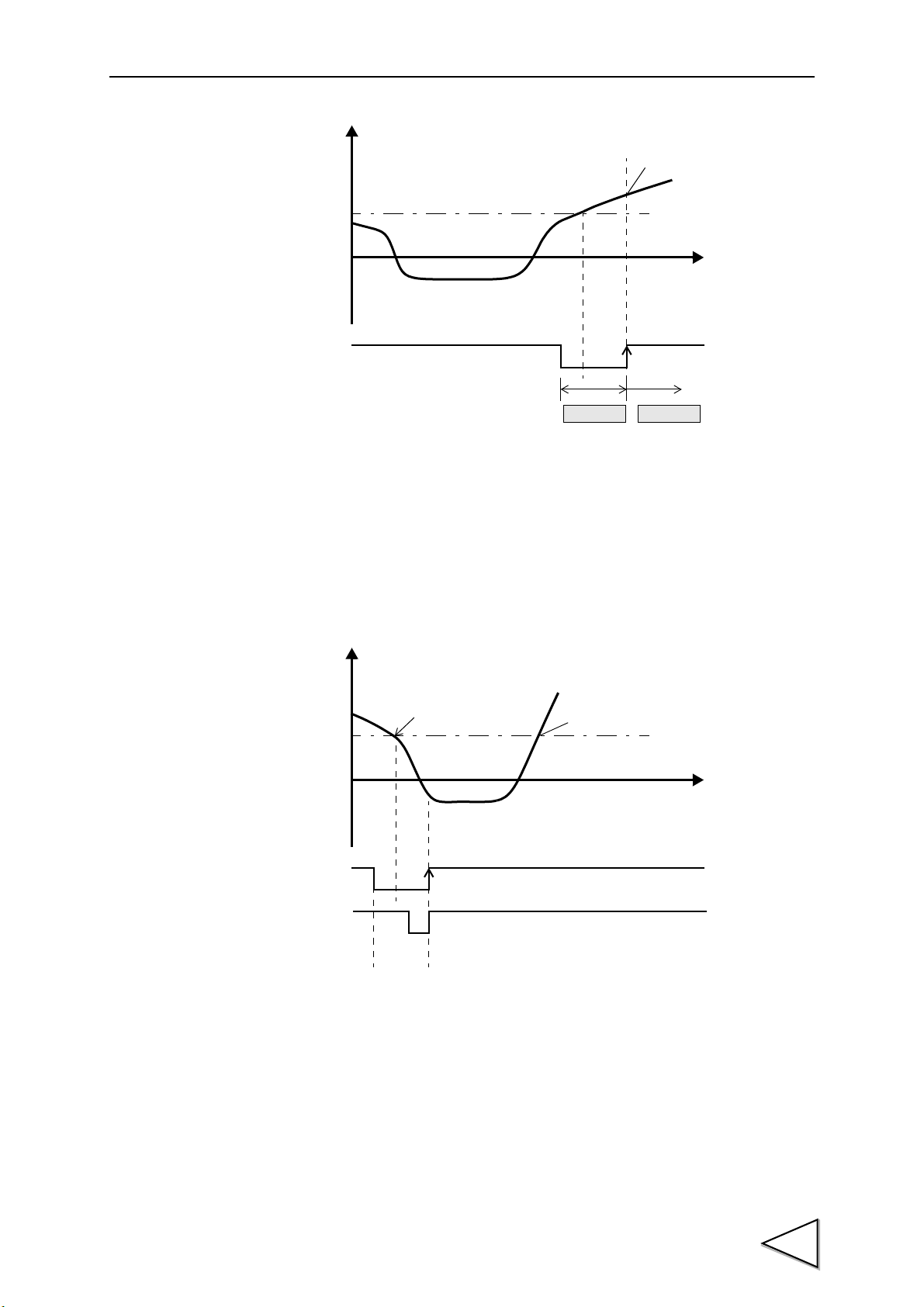
9.Method of Starting Measurement
+
START
t
WAIT 2
SAMPLE
OFF
ON
Start of waveform capturing
Waveform
start level
Status display
+
START
t
A
B
STOP
OFF
ON
OFF
ON
Start of waveform capturing
Waveform
start level
Trigger
Example 2
* If a HI or LO alarm is given at the same time when waveform capturing ends,
the waveform is registered in the rejected waveform area.
Example 3
* The level edge is cleared when the STOP signal is turned on with the START signal
ON. Therefore, waveform capturing will not start until the level edge at "B" is
established. (Waveform capturing starts at "A" if the STOP signal is not turned on.)
44
Page 59
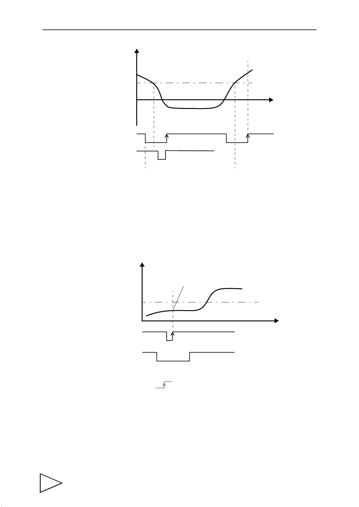
9.Method of Starting Measurement
+
START
t
C
E
STOP
D
OFF
ON
OFF
ON
Waveform
start level
Start of waveform capturing
+
START
t
OFF
ON
OFF
ON
Start of waveform capturing
Waveform
start level
Capture start
by external signal
Example 4
* In the above case, since the START signal is turned on again at "D", the state of "C" is
restored, where the return level edge and the rising edge of the START signal are
awaited. Therefore, waveform capturing finally starts at "E".
Example 5
* If the signal "Capture start by external signal" is ON when the START signal turns
from ON to OFF , waveform capturing starts immediately irrespective of
whether or not the input signal crosses over the Waveform Start Level.
45
Page 60

9.Method of Starting Measurement
・The minimum pulse width of START/STOP is Ts+0.8msec.
(Ts: 1-sampling interval. See "7-2. Sampling Rate" P40.)
・Operation when the STOP signal is input
- WAITL status cancel
If the STOP signal is input in WAITL status, the status is
forcedlyshifted to STOP status (sampling is not performed).
- WAIT2 status cancel
If the STOP signal is input in WAIT2 status, the status is shifted
as follows:
1. If the waveform has already crossed over the sampling start
level, the level edge is cancelled by the first STOP signal, and
the status is shifted to STOP status (sampling is not
performed) by the second STOP signal.
2. If the sampling start level has not been crossed, the status is
shifted to STOP status (sampling is not performed)
immediately after the STOP signal is input.
After waveform capturing ends with the STOP signal or excess of
2048 points, etc., approximately 300msec or more are required until
the next START signal becomes acceptable.
46
Page 61

10.Multi-Hold Mode
0123
Peak Hold
Inflection A Valley HoldSample
Operation ch
Hold
10. Multi-Hold Mode
10-1. Function
In the Multi-Hold mode, necessary points are detected in the displayed waveform to
make a judgment such as a High/Low Limit Comparison. Up to 32 channels of hold
types, High and Low Limits, etc. can be stored, which can be switched by external
signals or can automatically be switched by using the Auto Code Up function. Detected
hold points are displayed on a graph with a "+" mark.
10-2. Setting and Operating Method
1. Set desired value(s) [0 ~ 31 (32: all channel number selection)] under Channel
Number Selection in Code Setting, and set each item such as the High and Low
Limits.
2. Input the channel number(s) set in "1." by using channel selection signals (CODE 1
~ 16) to set operation channel(s).
3. Sampling can be performed with the value(s) set in "1.".
4. By also inputting set value(s) to other channel number(s) in "1." beforehand,
sampling can be performed under various set conditions by switching operation
channels (CODE 1 ~ 16) during sampling.
Example
47
Page 62
10-3. Hold Functions
Switching operation channels during sampling will result in the
following operation.
1. Data of the Judgment output signal (LO1,OK1,HI1) will be
accumulated and output by (LO 2 , O K 2 , H I 2 ).
2. The judgment operation is internally reset once, but it is not
necessary to cross over the Hold Start Level again for in Inflection
Point Hold, etc.
・ Ts is a sampling interval [msec].
(Ts=1.0 at 1kHz, and Ts=5.0 at 200Hz for example.)
・ The High/low Limit Judgment output is determined within
0.8msec after the COMPLETE signal is determined.
10.Multi-Hold Mode
Points are taken out of waveforms to make a High/Low Limit Comparison by the hold
functions, including Sample Hold, Peak Hold, Valley Hold, Peak-to-peak Hold, Relative
Maximum / Relative Minimum Value Hold, Inflection Point Hold, etc.
Here, detailed operation of each hold is explained.
48
Page 63

10.Multi-Hold Mode
t2t1
t
+
T/H
COMPLETE
OFF
ON
OFF
ON
OFF
ON
Sensor input value
Indicated value
Hold period
Determination
High/Low
Limit
Output
Judgment
10-3-1. Sample Hold
A point is held when the T/H signal is turned on
49
t1: Delay time between the instant when the T/H signal is input and the instant when the
t2: Delay time between the instant when the T/H signal is cancelled and the instant when
indicated value is held.
Ts+0.8msec (max.)
the indicated value returns to tracking.
Ts+0.8msec (max.)
Page 64
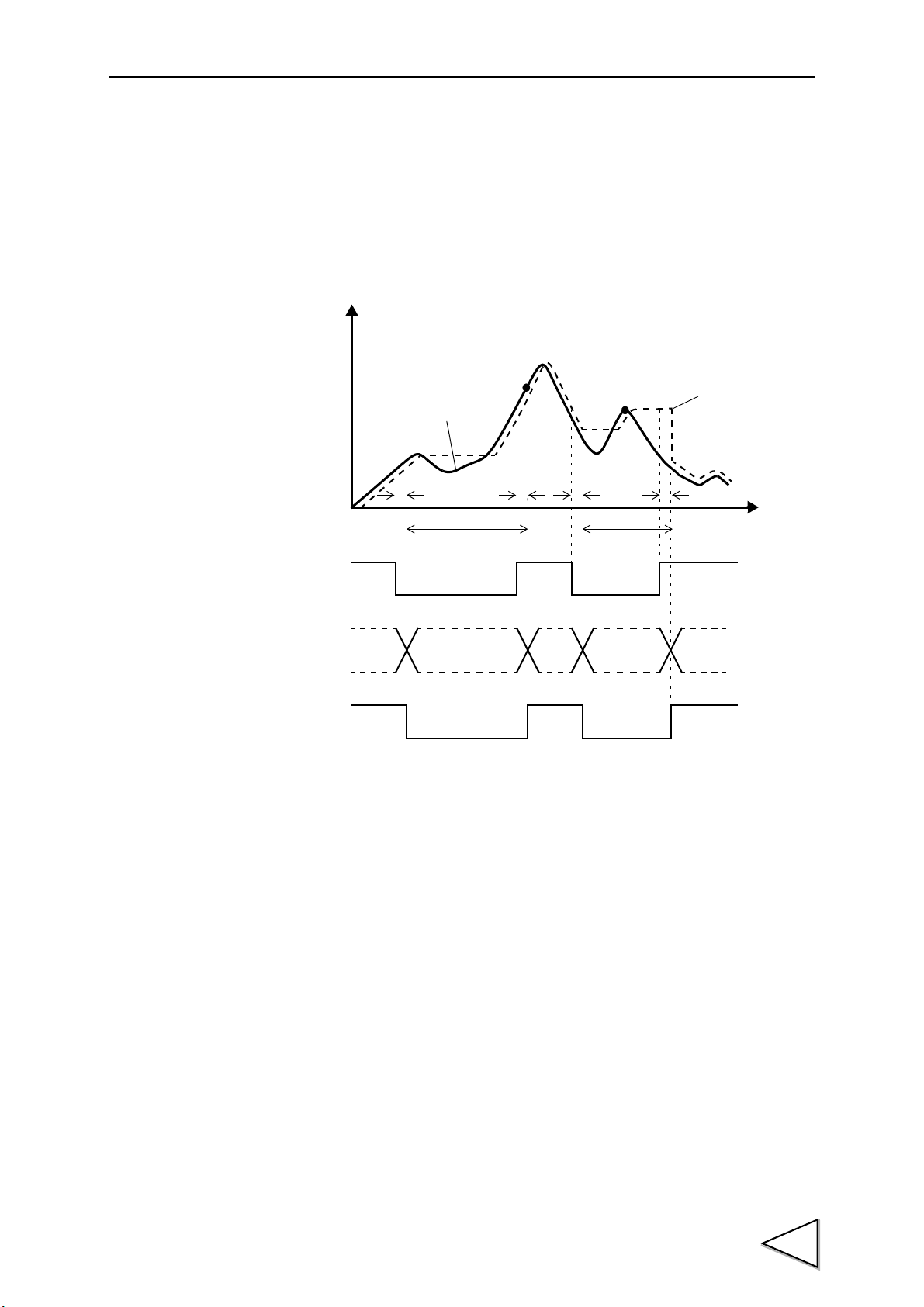
10-3-2. Peak Hold
t2
t
+
T/H
COMPLETE
t1t2t1
Note: During the indeterminate period, the Judgment output
varies with variations in the input waveform. However, the
COMPLETE output is kept on during the indeterminate
period. Read the result of judgment when the indicated
value becomes stable (immediately before the rising
edge of T/H).
OFF
ON
OFF
ON
OFF
ON
Sensor input value
Indicated value
Detection/hold period Detection/hold
period
Indeterminate
period (Note
High/Low
Limit
Output
Judgment
The maximum value (peak value) in the positive direction is held.
10.Multi-Hold Mode
t1: Delay time between the instant when the T/H signal is input and the instant when the
indicated value is held.
Ts+0.8msec (max.)
t2: Delay time between the instant when the T/H signal is cancelled and the instant when
the indicated value returns to tracking.
Ts+0.8msec (max.)
50
Page 65

10.Multi-Hold Mode
t2
t
+
T/H
COMPLETE
t1t2t1
OFF
ON
OFF
ON
OFF
ON
Sensor input value
Detection/hold period
Detection/hold period
Indicated value
Indeterminate
period (Note
Indeterminate
period (Note
Note: During the indeterminate period, the Judgment output
varies with variations in the input waveform. However, the
COMPLETE output is kept on during the indeterminate
period. Read the result of judgment when the indicated
value becomes stable (immediately before the rising
edge of T/H).
High/Low
Limit
Output
Judgment
10-3-3. Valley Hold
The maximum value (valley value) in the negative direction is held.
t1: Delay time between the instant when the T/H signal is input and the instant when the
indicated value is held.
Ts+0.8msec (max.)
t2: Delay time between the instant when the T/H signal is cancelled and the instant when
the indicated value returns to tracking.
Ts+0.8msec (max.)
51
Page 66
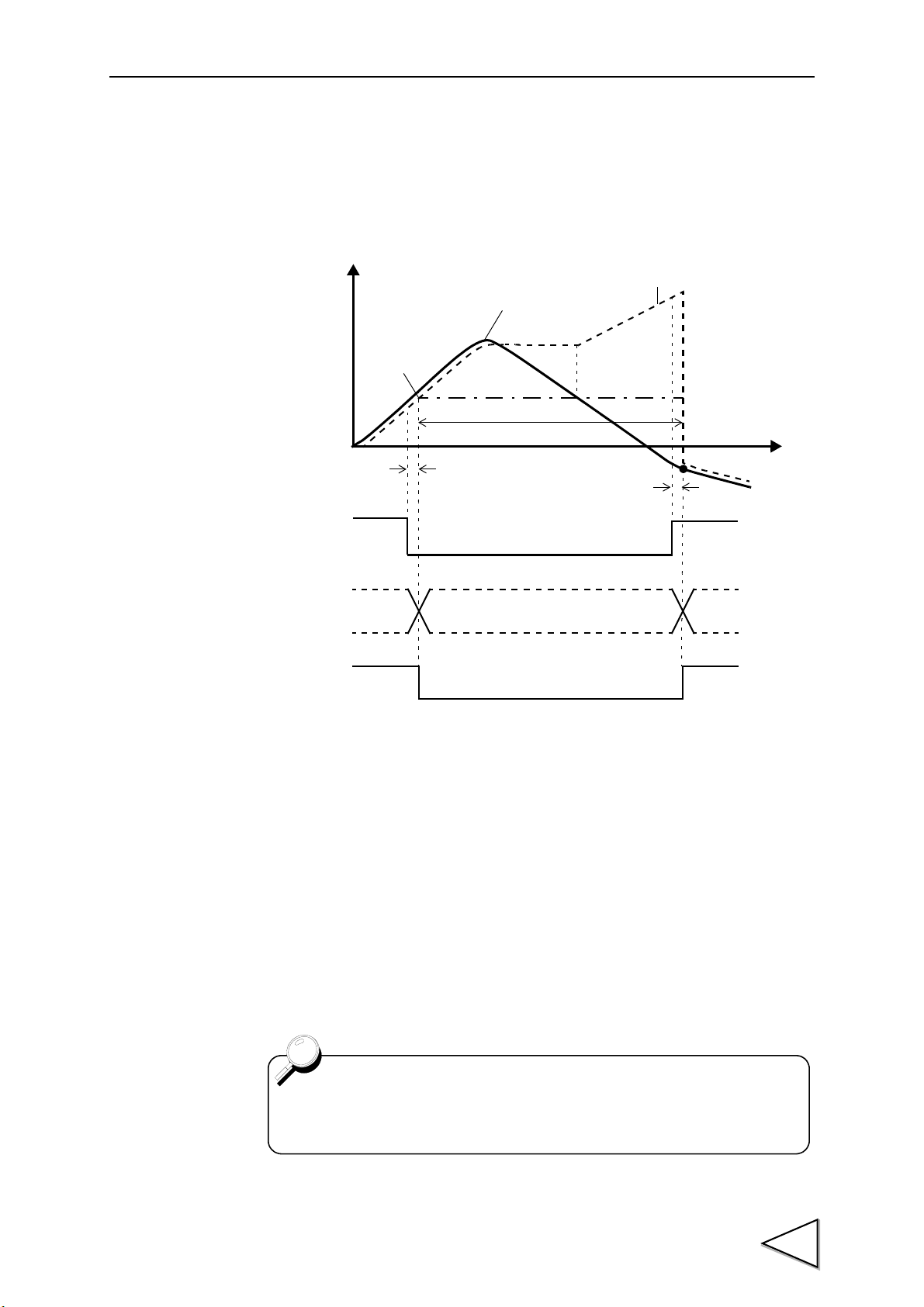
10-3-4. P-P (Peak-to-Peak) Hold
t
+
T/H
t2
t1
Indicated value=0
OFF
ON
OFF
ON
OFF
ON
COMPLETE
Indicated value
Sensor input value
Detection/hold period
Indeterminate
period (Note
Reference line
Indicated value=0
(Here is referenced
only for the hold period.)
Note: During the indeterminate period, the Judgment output
varies with variations in the input waveform. However, the
COMPLETE output is kept on during the indeterminate
period. Read the result of judgment when the indicated
value becomes stable (immediately before the rising
edge of T/H).
High/Low
Limit
Output
Judgment
Hereinafter, display in every Peak-to-peak Hold is as follows:
・ The hold is displayed with a yellow "+" mark.
・ No High/Low Limit Graph is displayed.
The maximum value of difference from the value of the instant when the T/H signal is
turned on is held.
10.Multi-Hold Mode
t1: Delay time between the instant when the T/H signal is input and the instant when the
indicated value is held.
Ts+0.8msec (max.)
t2: Delay time between the instant when the T/H signal is cancelled and the instant when
the indicated value returns to tracking.
Ts+0.8msec (max.)
52
Page 67
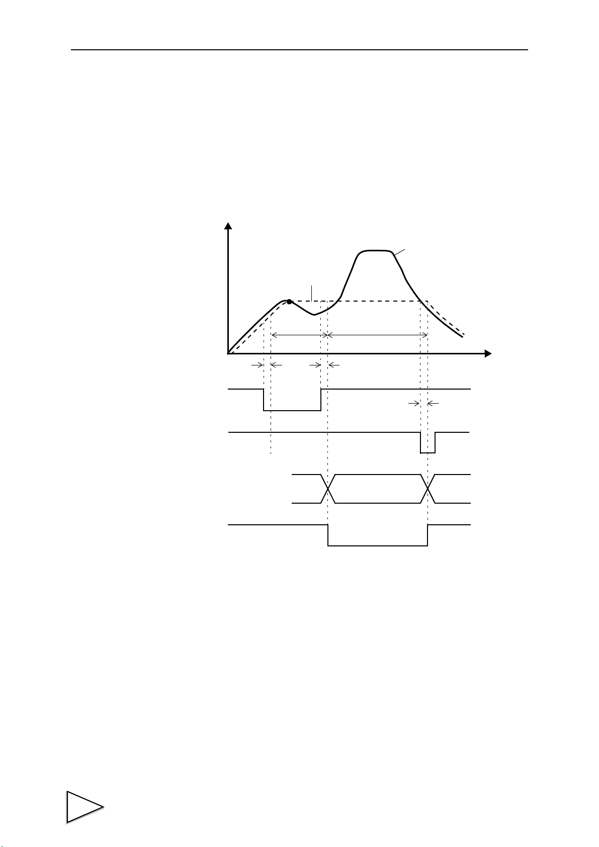
10.Multi-Hold Mode
t3
t
+
T/H
COMPLETE
t2t1
H/M
OFF
ON
OFF
ON
OFF
ON
OFF
ON
Determination
Indicated value
Sensor input value
Hold period
Detection
period
High/Low
Limit
Output
Judgment
10-3-5. Period Specified Hold (Peak, Valley, P-P)
The hold detection period is specified externally by this method. A reset signal (T/H) is
required for canceling the hold.
Example: Period Specified Peak Hold
t1: Delay time between the instant when the H/M signal is input and the instant when the
hold is detected.
Ts+0.8msec (max.)
t2: Delay time between the instant when the H/M signal is cancelled and the instant when
the hold is determined.
Ts+0.8msec (max.)
t3: Minimum reset signal width required for canceling the hold.
Ts+0.8msec (min.)
53
Page 68
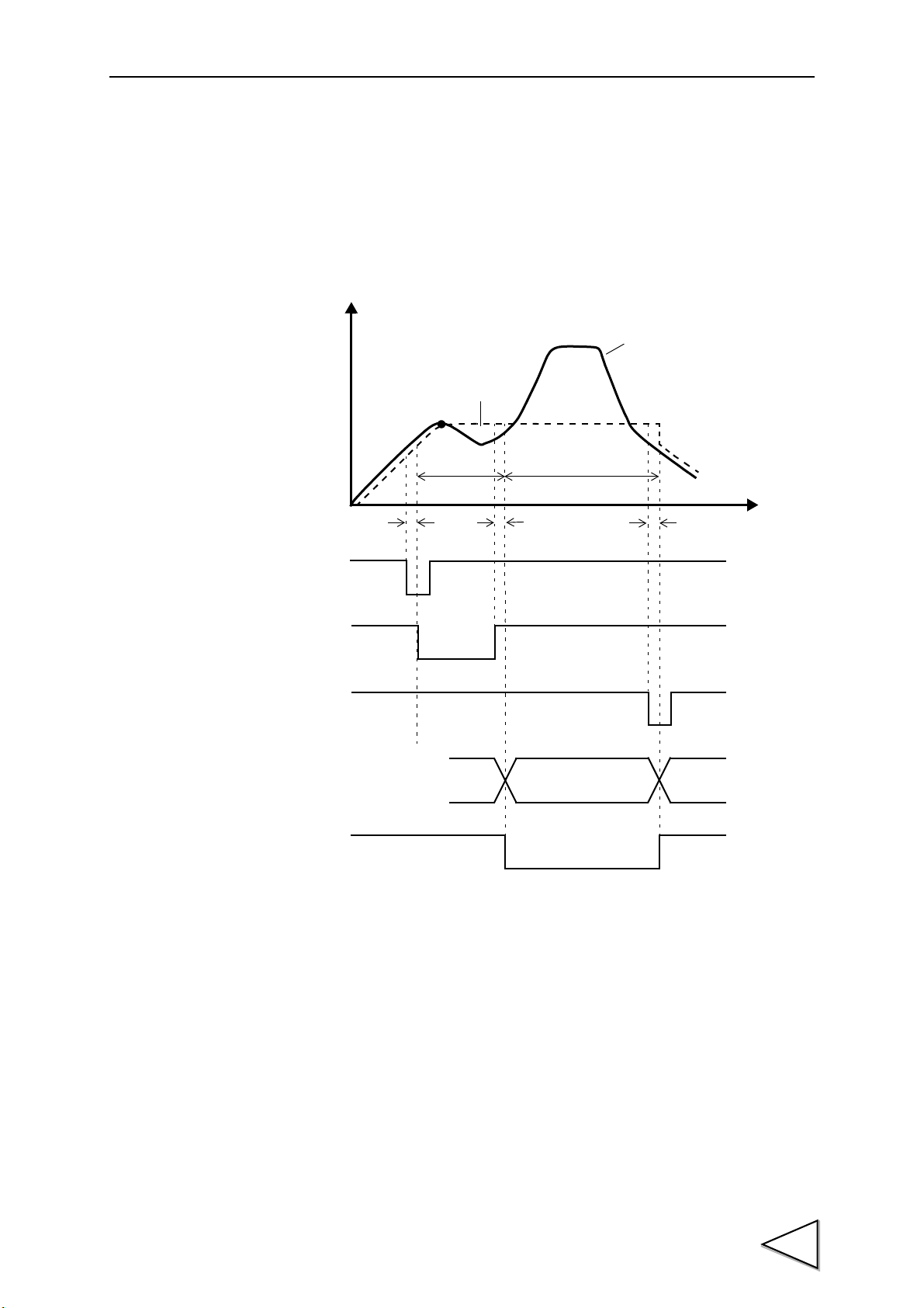
10-3-6. Time Specified Hold (Peak, Valley, P-P)
Determination
Indicated value
Sensor input value
Hold period
Detection
period
t3
t
+
COMPLETE
t2t1
H/M
T/H
OFF
ON
OFF
ON
OFF
ON
OFF
ON
OFF
ON
Hold Detect
Time
High/Low
Limit
Output
Judgment
The hold detection period is within the set time (Hold Detect Time) from the triggered
point in time by this method. A reset signal (T/H) is required for canceling the hold.
Example: Time Specified Peak Hold
10.Multi-Hold Mode
t1: Delay time between the instant when the H/M signal is input and the instant when the
hold is detected.
Ts+0.8msec (max.)
t2: Delay time between the instant when the hold detect time expires and the instant
when the hold is determined.
Ts+0.8msec (max.)
t3: Minimum reset signal width required for canceling the hold.
Ts+0.8msec (min.)
54
Page 69
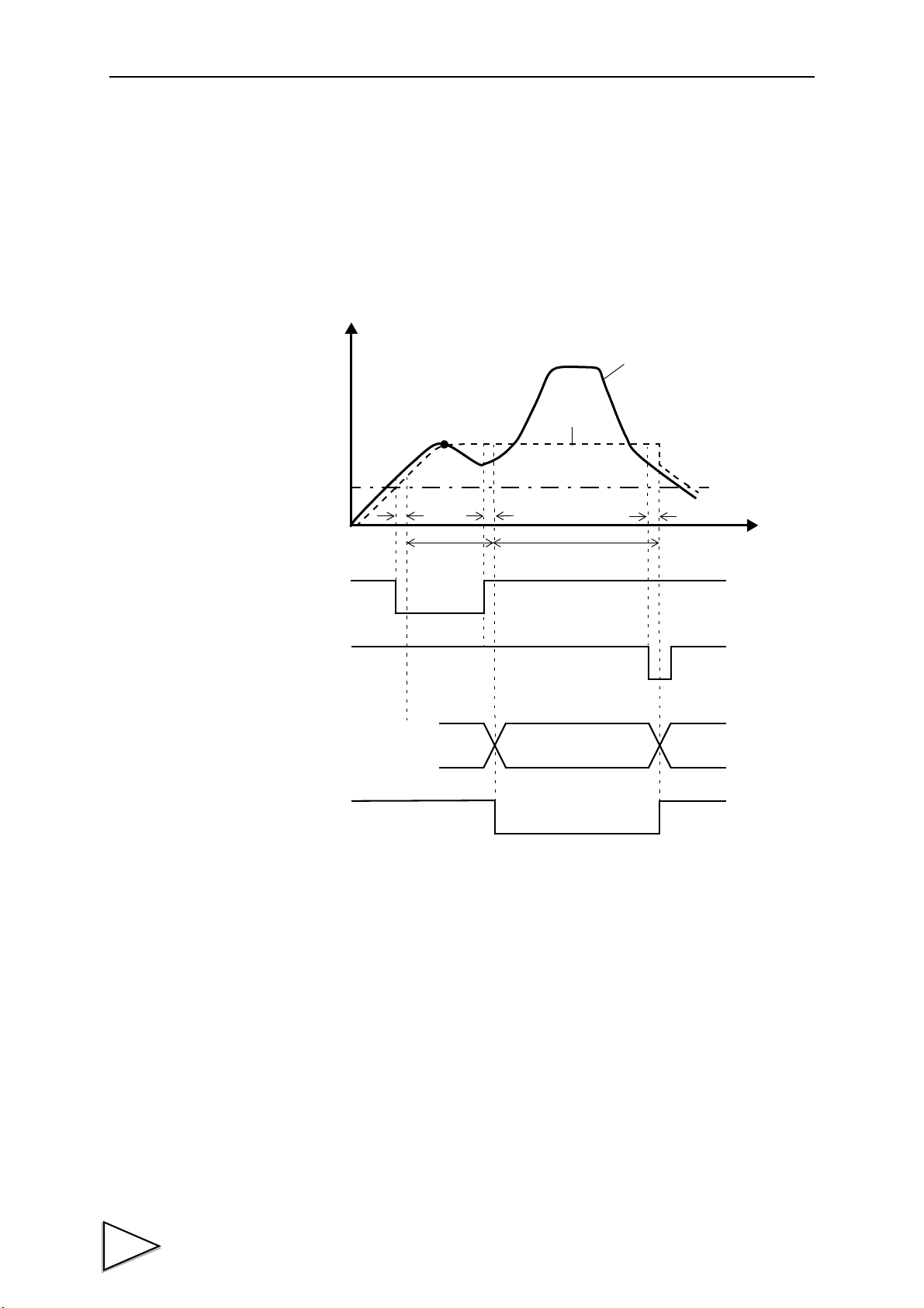
10.Multi-Hold Mode
t3
t
+
COMPLETE
t2t1
T/H
Hold Start Level
OFF
ON
OFF
ON
OFF
ON
OFF
ON
Hold Detect
Time
Hold period
Detection
period
Sensor input value
Indicated value
Determination
High/Low
Limit
Output
Judgment
10-3-7. Time Specified Automatic Hold (Peak, Valley, P-P)
The hold detection period is within the set time (Hold Detect Time) from the instant
when the indicated value crosses over the waveform start level. A reset signal (T/H) is
required for canceling the hold.
Example: Time Specified Automatic Peak Hold
t1: Delay time between the instant when the indicated value exceeds the hold start level
and the instant when the hold is detected.
Ts msec (max.)
t2: Delay time between the instant when the hold detect time expires and the instant
when the hold is determined.
Ts+0.8msec (max.)
t3: Minimum reset signal width required for canceling the hold.
Ts+0.8msec (min.)
55
Page 70
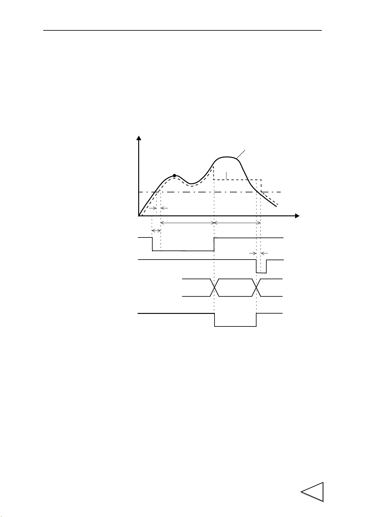
10.Multi-Hold Mode
t3
t
+
H/M
t2
t1
COMPLETE
OFF
ON
OFF
ON
OFF
ON
T/H
OFF
ON
Indicated value
Sensor input value
Hold Start Level
Hold period
Detection
period
Determination
High/Low
Limit
Output
Judgment
10-3-8. Relative Maximum Value / Relative Minimum Value Hold
Detection is performed while the H/M signal is ON from the instant when the indicated
value crosses over the Waveform Start Level. The hold can be cancelled by turning on
the T/H signal as a reset signal.
Example: Relative Maximum Value Hold
t1: Delay time between the instant when the indicated value exceeds the hold start level
and the instant when the hold is detected.
Ts msec (max.)
t2: Delay time between the instant when the H/M signal is input and the instant when it is
detected that the indicated value exceeds the hold start level.
Ts+0.8msec (max.)
t3: Delay time between the instant when the T/H signal is input and the instant when the
indicated value returns to tracking.
Ts+0.8msec (max.)
56
Page 71
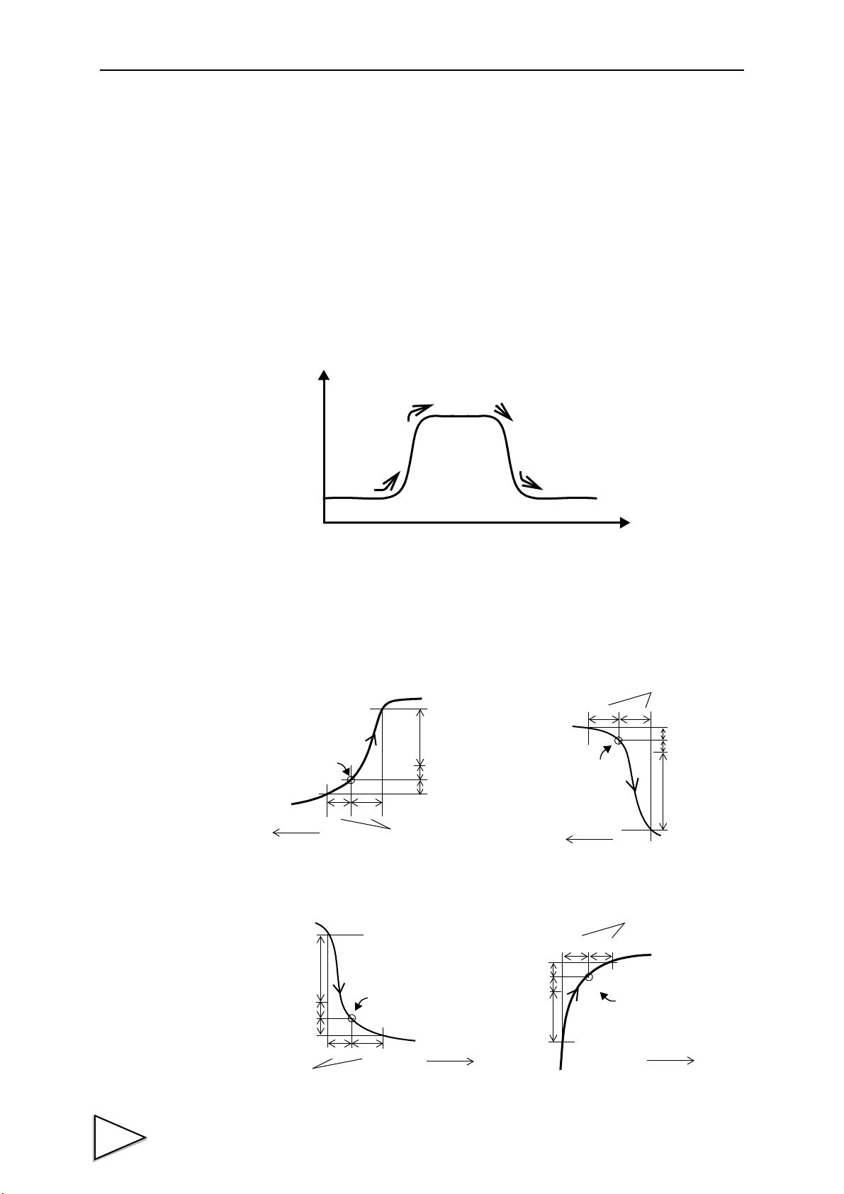
10.Multi-Hold Mode
+
+
+
+
Four types of Inflection Point Hold
Load
Time
Inflection Point Hold A
Inflection Point Hold B
Inflection Point Hold C
Inflection Point Hold D
AB
D
C
C
a
a
AB
C
C
D
Inflection Point Hold A
Inflection Point Hold B
Inflection Point Hold C
Inflection Point Hold D
AB
a
D
C
C
AB
D
C
C
a
Slope change point
Slope change point
Slope change point
Slope change point
Slope Detection
Intervals
Slope Detection Intervals
Slope Detection Intervals
Slope Detection
Intervals
Preliminary Slope
Preliminary Slope
detection point
Preliminary Slope
Detection Point
Detection Point
Preliminary Slope
detection point
10-3-9. Four Types of Inflection Point Hold
Detection starts when the H/M signal is input and the indicated value crosses over the
Hold Start Level. Detection is performed while the H/M signal is ON. The COMPLETE
output is made immediately when there is a minute slope. Therefore, if the Judgment
output is taken in immediately after the COMPLETE output is made, correct results may
not be able to be obtained as is the case with the peak hold.
Take in the Judgment output after determination of the hold by turning off the H/M
signal. The hold can be cancelled by turning on the T/H signal as a reset signal.
Each inflection point hold is explained by the method in "16-2-12. Minimum Slope
Detection Value / Slope Detection Interval A / Slope Detection Interval B / Preliminary
Slope Detection Point" P118. (Point a is held as an inflection point when the amount of
change D exceeds the set "Minimum Slope Detection Value".
57
Page 72
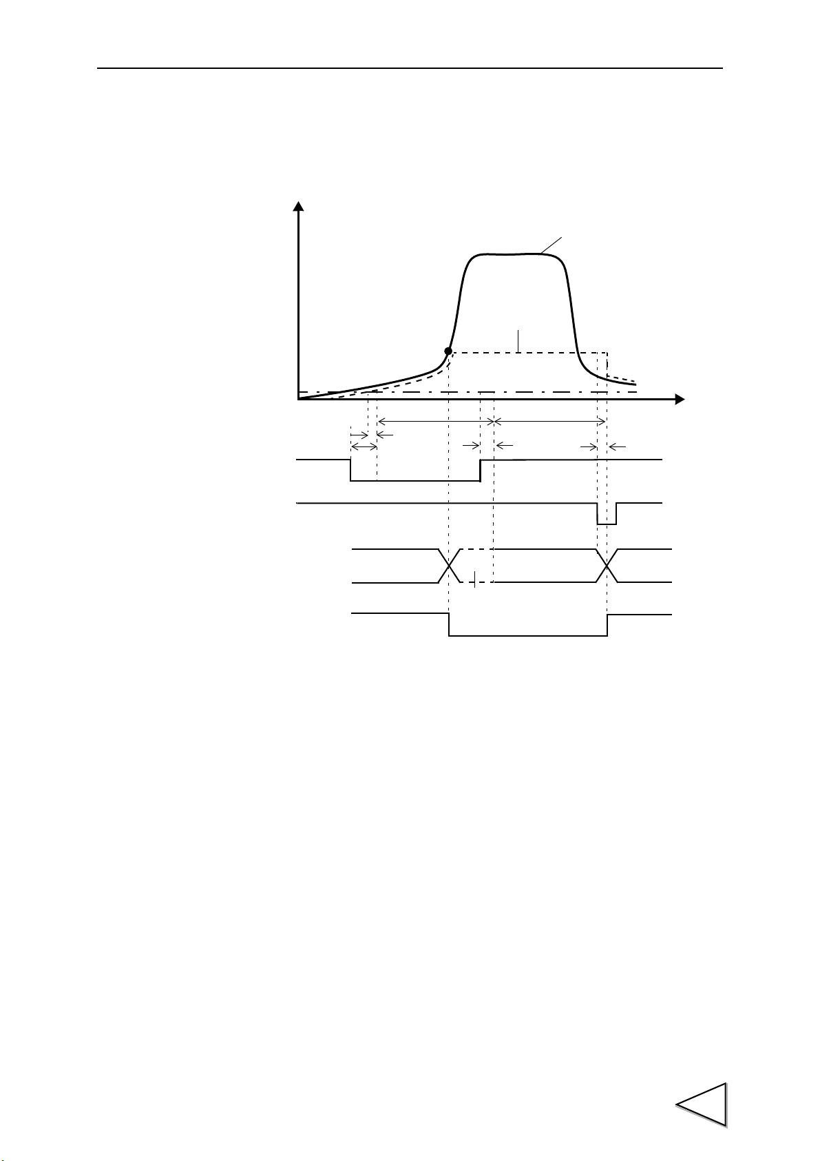
10-3-9-1. Inflection Point Hold A
t4
t
+
H/M
t2
t1
Hold Start
OFF
ON
OFF
ON
OFF
ON
COMPLETE
Note: During the indeterminate period, the Judgment output varies with
variations in the input waveform. However, the COMPLETE output is
kept on during the indeterminate period. Read the result of judgment
after determination of the judgment by turning off the H/M signal.
t3
T/H
ON
OFF
Level
Sensor input value
Indicated value
Hold period
Detection/hold period
Determination
Indeterminate
period (Note
High/Low
Limit
Output
Judgment
10.Multi-Hold Mode
t1: Delay time between the instant when the indicated value exceeds the hold start level
and the instant when the hold is detected.
Ts msec (max.)
t2: Delay time between the instant when the H/M signal is input and the instant when it is
detected that the indicated value exceeds the hold start level.
Ts+0.8msec (max.)
t3: Delay time between the instant when the H/M signal is cancelled and the instant when
the hold is determined.
Ts+0.8msec (max.)
t4: Delay time between the instant when the T/H signal is input and the instant when the
indicated value returns to tracking.
Ts+0.8msec (max.)
58
Page 73

10.Multi-Hold Mode
t4
t
+
H/M
t2
t1
OFF
ON
OFF
ON
OFF
ON
COMPLETE
t3
T/H
ON
OFF
Hold Start
Level
Sensor input value
Indicated value
Detection / hold period
Hold period
Indeterminate
period (Note
Determination
Note: During the indeterminate period, the Judgment output varies with
variations in the input waveform. However, the COMPLETE output is
kept on during the indeterminate period. Read the result of judgment
after determination of the judgment by turning off the H/M signal.
High/Low
Limit
Output
Judgment
10-3-9-2. Inflection Point Hold B
t1: Delay time between the instant when the indicated value exceeds the hold start level
and the instant when the hold is detected.
Ts msec (max.)
t2: Delay time between the instant when the H/M signal is input and the instant when it is
detected that the indicated value exceeds the hold start level.
Ts+0.8msec (max.)
t3: Delay time between the instant when the H/M signal is cancelled and the instant when
the hold is determined.
Ts+0.8msec (max.)
t4: Delay time between the instant when the T/H signal is input and the instant when the
indicated value returns to tracking.
Ts+0.8msec (max.)
59
Page 74

10-3-9-3. Inflection Point Hold C
t4
t
+
H/M
t2
t1
OFF
ON
OFF
ON
OFF
ON
COMPLETE
t3
ON
OFF
T/H
Hold Start
Level
Sensor input value
Indicated value
Detection/hold period
Hold period
Indeterminate
period (Note
Determination
Note: During the indeterminate period, the Judgment output varies with
variations in the input waveform. However, the COMPLETE output is
kept on during the indeterminate period. Read the result of judgment
after determination of the judgment by turning off the H/M signal.
High/Low
Limit
Output
Judgment
10.Multi-Hold Mode
tt1: Delay time between the instant when the indicated value exceeds the hold start level
and the instant when the hold is detected.
Ts msec (max.)
t2: Delay time between the instant when the H/M signal is input and the instant when it is
detected that the indicated value exceeds the hold start level.
Ts+0.8msec (max.)
t3: Delay time between the instant when the H/M signal is cancelled and the instant when
the hold is determined.
Ts+0.8msec (max.)
t4: Delay time between the instant when the T/H signal is input and the instant when the
indicated value returns to tracking.
Ts+0.8msec (max.)
60
Page 75
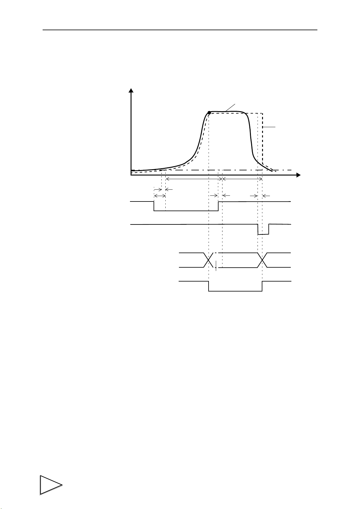
10.Multi-Hold Mode
t4
t
+
H/M
t2
t1
OFF
ON
OFF
ON
OFF
ON
COMPLETE
t3
T/H
ON
OFF
Sensor input value
Indicated value
Hold Start
Level
Detection/hold period
Hold period
Indeterminate
period (Note
Determination
Note: During the indeterminate period, the Judgment output varies with
variations in the input waveform. However, the COMPLETE output is
kept on during the indeterminate period. Read the result of judgment
after determination of the judgment by turning off the H/M signal.
High/Low
Limit
Output
Judgment
10-3-9-4. Inflection Point Hold D
t1: Delay time between the instant when the indicated value exceeds the hold start level
and the instant when the hold is detected.
Ts msec (max.)
t2: Delay time between the instant when the H/M signal is input and the instant when it is
detected that the indicated value exceeds the hold start level.
Ts+0.8msec (max.)
t3: Delay time between the instant when the H/M signal is cancelled and the instant when
the hold is determined.
Ts+0.8msec (max.)
t4: Delay time between the instant when the T/H signal is input and the instant when the
indicated value returns to tracking.
Ts+0.8msec (max.)
61
Page 76

10-3-10. Pulse Hold
t2
t1
OFF
ON
COMPLETE
t3
t3
t3
OFF
ON
OFF
ON
OFF
ON
OFF
ON
OFF
ON
HOLD3
HOLD2
HOLD1
T/H
Sensor input value
Indicated value
Detection / hold period
Determination Determination Determination
High/Low
Limit
Output
Judgment
t
+
Values are held when external pulses are input. There are three pulse inputs.
Only one point is held for each pulse input.
Also, for the set values of High and Low Limits, the target channels are fixed as
HOLD 1: operation ch, HOLD 2: operation ch+1, and HOLD 3: operation ch+2. (When
the operation ch is 31ch, the target channels are fixed as HOLD 1: 31ch, HOLD 2: 0ch,
and HOLD 3: 1ch.)
10.Multi-Hold Mode
Inputs of the same signal from the second time onward are ineffective.
t1: Delay time between the instant when the T/H signal is input and the instant when
detection starts.
Ts+0.8msec (max.)
t2: Delay time between the instant when the T/H signal is cancelled and the instant when
the indicated value returns to tracking.
Ts+0.8msec (max.)
t3: Delay time between the instant when the HOLD signal is input and the instant when
the indicated value is held.
Ts+0.8msec (max.)
62
Page 77

10.Multi-Hold Mode
・ The analog CH used for measurement depends on the Select Analog
CH setting for the operation ch at which sampling starts. The Select
Analog CH setting for operation ch+1/operation ch+2 is ineffective.
・ For the High/Low Limit Judgment output, the result of judgment of the
latest input pulse is output to " LO1,OK1,HI1", and the results of
judgment of all input pulses are accumulated and output to
" LO2,OK2,HI2".
General of the hold functions
The delay times for the Judgment output and COMPLETE do not
include the delay time in the analog circuit (low-pass filter). Also,
calculations have been made with no digital filter. Since the
Judgment output and COMPLETE output are made with respect to
analog-filter- and digital-filter-processed values, the transfer of
signals becomes slow and the delay of each output increases as
each filter is strengthened.
When Pulse Hold is selected by the operation ch at which sampling starts, the main
screen in graphic display is as follows.
・ High and Low Limit Graphs are displayed according to the pulse position.
・ The results of measurement are displayed from the left in the order of pulse input.
・ When no pulse is input, the result of measurement is displayed as "-----."
63
Page 78

11. Hysteresis Mode
Sampling waveforms are shown by the solid lines. The hysteresis return
output is turned ON when the return waveform sampling starts, and is turned
OFF upon its completion. (See "4-3-2. Input and Output Signals" P25.
Hysteresis return retrieval period (*)
Return determination
The hysteresis return output
is turned on.
Displacement
Hysteresis interval Hysteresis interval
The return in this period is ineffective.
If the operation ch is switched and any hold point occurs in
the hysteresis return retrieval period (*), no "+" mark is
displayed when the waveform is displayed.
11-1. Function
In the Hysteresis mode, go and return waveforms changing with displacement are
sampled, and necessary points in the waveforms are detected to make judgments such as
High/Low Limit Comparisons.
The maximum sampling rate is 2kHz. The operation is almost the same as in the Multi-
Hold mode except for displacement on the X-axis, go and return samplings, and the
maximum sampling rate of 2kHz.
11-2. Setting and Operating Method
11.Hysteresis Mode
1. Make settings as in "10-2. Setting and Operating Method" P47, and
"16-2-14. Hysteresis Interval" P119.
2. Retrieval of a return sampling is as follows
3. The scale of the X-axis and handling of sudden changes in displacement input are the
same as those in the Waveform and Displacement Comparison mode. (See "13-5.
Waveform and Displacement Comparison Mode" P74.)
4. Go and return waveforms are displayed on the graph in blue and red, respectively.
64
Page 79

12.Hysteresis 2
12.Hysteresis 2
12-1. Function
In the Hysteresis 2 mode, go and return waveforms changing with displacement are
sampled for High/Low Limit Comparisons of go measured values and differences
between go and return measured values (go - return) on the displacement points where
external pulses are input.
The operation is the same as in the Hysteresis mode except for the holding method and
the High/Low Limit Comparison method.
12-2. Setting and Operating Method
1. Sampling is the same as in the Hysteresis mode. (See "11-2. Setting and Operating
Method" P64.)
2. Measure the High and Low Limits.
・ Go measured value comparison: Uses the High Limit / Low Limit.
・ Between-go-and-return difference comparison: Uses the HI-HI Limit / LO-LO
Limit. (See"16-2-7. High Limit / Low Limit / HI-HI/LO-LO Mode / HI-HI Limit /
LO-LO Limit" P109.)
3. Pulse Input
Determine displacement points by the ON edges of HOLD 1 ~ 3 (See"4-3-2. Input
and Output Signals" P25.) For the set values of High and Low Limits with respect to
each Pulse Input, the target channels are fixed as
HOLD 1: operation ch, HOLD 2: operation ch+1, and HOLD 3: operation ch+2.
(When the operation ch is 31ch, the target channels are fixed as HOLD 1: 31ch,
HOLD 2: 0ch, and HOLD 3: 1ch.)
Also, the input / output specifications of each signal are the same as in Pulse Hold
(See "10-3-10. Pulse Hold" P62.) (The results of difference judgment are output when
the return displacement point=go pulse input displacement point.)
4. Start Sampling.
(See "9. Method of Starting Measurement" P43, and "16-2-9. Level Axis Select / Waveform
Start Level / Waveform Termination Level / Hold Start Level" P113.)
65
Page 80

12.Hysteresis 2
Differences between
go and return measured
values are displayed.
In the Hysteresis 2 mode, the main screen is displayed as follows:
・ High/Low Limit Waveforms are not displayed on the graph, and if the result of
comparison is an error, the result of measurement is displayed in red.
・ The results of measurement are displayed from the left in the order of pulse input.
・ When no pulse is input, the result of measurement is displayed as "-----".
In the hysteresis 2 mode, hold point display screen is as follows.
66
Page 81

12.Hysteresis 2
・ HI-HI Limit / LO-LO Limit Comparisons are not made.
・ If the operation ch is changed during measurement, the measurement is
stopped forcedly. (The results of previous judgments are not displayed.)
・ Each measurement will not be carried out until sampling starts.
・ Measurements are carried out with the Select Analog CH setting for the
operation ch at which sampling starts. The Select Analog CH setting for
operation ch+1/operation ch+2 is ineffective.
・ Do not input any pulse within the hysteresis interval because the result is
not judged normally.
・ No judgment is made if no pulse is input during go.
・ A difference judgment is made when the pulse-input displacement value
is reached during return measurement. (If two or more pulses are input at
the same displacement point during go measurement, judgments are
made by giving priority as pulse 1>pulse 2>pulse 3.)
・ Use of the Auto Code Up mode allows pulse input by the X-axis
measured value set under Code Up Point. (See "16-1. Method of Setting
the Operation ch" P100.)
67
Page 82

13.Waveform Comparison / Waveform and Displacement Comparison Mode
Waveform comparison mode ⇒ X-axis=time
Waveform and displacement
maximum sampling rate=2kHz
comparison mode
(analog input CH2)
X-axis=displacement
maximum sampling rate=4kHz
⇒
13.Waveform Comparison /
Waveform and Displacement Comparison Mode
13-1. Function
In the Waveform Comparison mode, waveforms changing with time (or displacement)
are sampled to make High/Low Limit Comparisons based on the sampled waveforms.
Sequential comparisons can be made with dynamically changing waveforms.
The point where the High/Low Limit Waveform is exceeded for the first time is
displayed on the graph with a "+" mark.
Also, any one of hold operations: Sample Hold, Peak Hold, and Valley Hold can be
executed simultaneously with the Waveform Comparison operation.
13-2. Setting and Operating Method
1. Decide Channel Number Selection in Code Setting, and set the following items.
・Select Analog CH
(in the Waveform Comparison mode. CH1 is fixed in the Waveform and Displacement
Comparison mode. See "7-4. X/Y-axis Setting by Operation Mode and Input CH"
P41.)
・ Level Axis Select
("Y-axis" is fixed in the Waveform Comparison mode. See "16-2-9. Level Axis Select
/ Waveform Start Level / Waveform Termination Level / Hold Start Level" P113.)
・Waveform Start Level
(unnecessary when used with the input signal "Capture start by external signal" ON.
See "16-2-9. Level Axis Select / Waveform Start Level / Waveform Termination Level
/ Hold Start Level" P113.)
・Waveform Termination Level (unnecessary when used with the input signal "waveform
termination level operation" OFF. See "16-2-9. Level Axis Select / Waveform Start
Level / Waveform Termination Level / Hold Start Level" P113.)
・For executing any hold operation, also set the following two items.
(See "13-7. Hold Operation" P78.)
i. Hold Setting (See "16-2-4. Hold Setting" P105.)
ii. HI-HI Limit / LO-LO Limit (See "16-2-7. High Limit / Low Limit / HI-HI/LO-
LO Mode / HI-HI Limit / LO-LO Limit" P109.)
68
Page 83

13.Waveform Comparison / Waveform and Displacement Comparison Mode
・ If the operation ch is changed during measurement, the
measurement is stopped forcedly. (The results of previous
judgments are not displayed.)
・ For hold operation, input the T/H signal as necessary.
MODE → Operation Mode → Operation Mode → Wave Comp.
or
Wave&Displace
2. Sample a waveform.
3. Edit the waveform as necessary.
4. Set the area.
5. Set the same value of Channel Number Selection set in "1." under Waveform Save.
(Register the waveform.)
6. By setting the channel having been set in "1." and "5." with channel selection
signals (CODE1 ~ 16: See "4-3-2. Input and Output Signals" P25.), measurements
can be carried out by using the values having been set in "1." and the waveform
registered in "5.". (Set the operation ch.)
13-3. Waveform Sampling Procedures
Waveform sampling can be performed efficiently by the following procedures. (It is
assumed that the F395 has been calibrated.)
For the setting / operating method of each function, see "13-7. Hold Operation" P78.
(For details of input and output signals, see "4-3-2. Input and Output Signals" P25.)
* If no step is shown for each item, select the item by the step of "MODE → Waveform
Sampling".
1. Set "Wave Comp." or "Waveform&Displace" under "Operation Mode".
69
Page 84
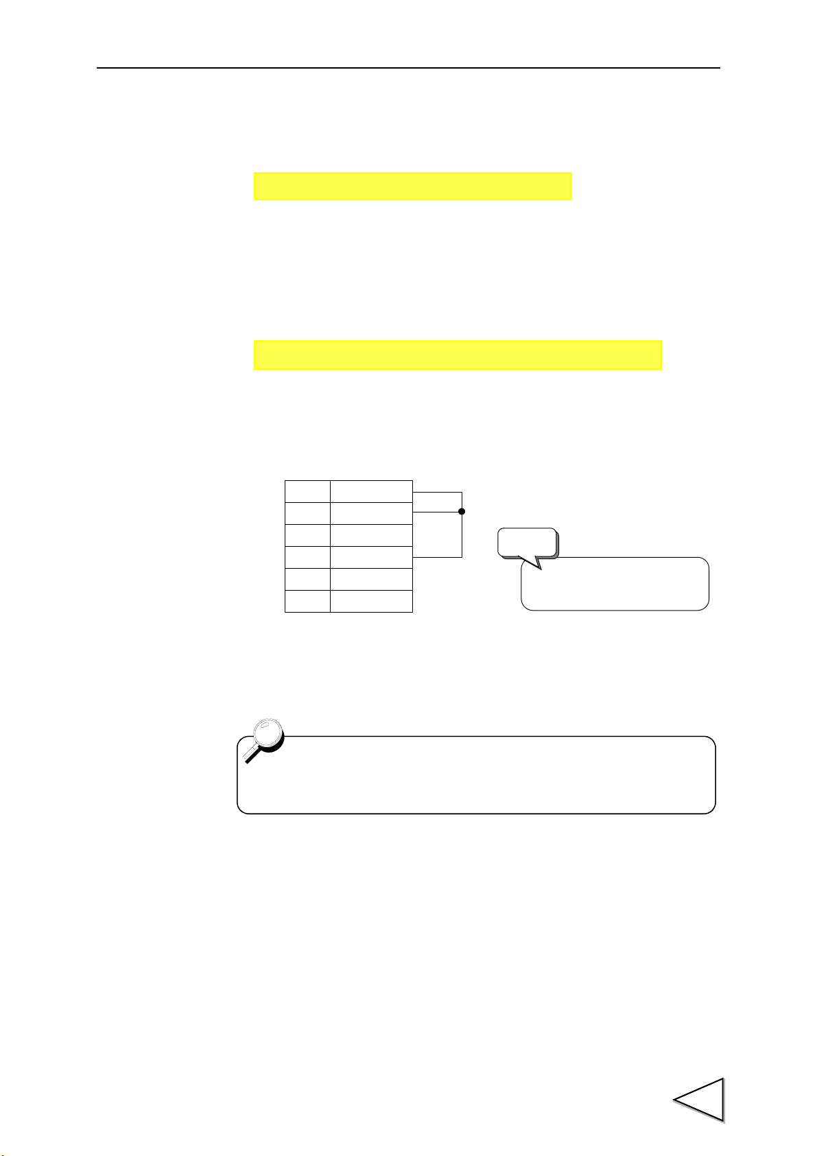
13.Waveform Comparison / Waveform and Displacement Comparison Mode
MODE → Operation Mode → Sample Rate
MODE → Code Set → Basic: Wave Start Level / Wave End Level
10 COM
11 CODE1
12 CODE2
13 CODE4
14 CODE8
36 CODE16
Open CODE16.
(Do not use.)
Request
Example: 5ch
Control connector
A waveform is input in synchronization with the
"Waveform Drawing" function.
For details, see "9. Method of Starting Measurement" P43.
2. Set 100Hz under "Sampling Rate". However, it is normally 2kHz in the Displacement
mode. For use in the Displacement mode, operations in "5." ~"9." are unnecessary,
therefore perform operation in "10." after "3." and "4.".
3. Set "Waveform Start Level" and "Waveform Termination Level" at the desired ch (0 ~
15).
Waveform Start Level: Normally set a value close to zero (approx. the increment ×
10). Set a slightly larger value if noise is large.
4. Set desired channel(s) with external channel selection signals.
5. Exit the setting menu, go to the main screen, input the START signal externally, and
then input a test waveform.
70
Page 85

13.Waveform Comparison / Waveform and Displacement Comparison Mode
6. When the waveform is displayed on the screen, decide the scaling, etc., so that the full
waveform is properly displayed by "Waveform Reading".
7. Move the pointer cursor to the end of the waveform, and examine the length of one
cycle of the waveform.
8. Decide the sampling rate most suitable for the input waveform.
(Maximum data of one waveform) ÷ (Length of one cycle of the waveform [sec])
The frequency obtained by this expression is the most suitable sampling rate. When
the above waveform is taken for example: 2000 ÷ 6 sec.=333.33Hz
The closest value under this frequency is the most suitable sampling rate. (It is 200Hz
for the F395.)
9. Select the most suitable value based on the above calculation under "Sampling Rate".
10. Before waveform sampling, execute "Waveform Clear" first.
11. Execute "Waveform Sampling".
12. Press the key on the screen to input the START signal externally,
and input a waveform for sampling.
71
13. Select whether or not to adopt the input waveform.
Page 86
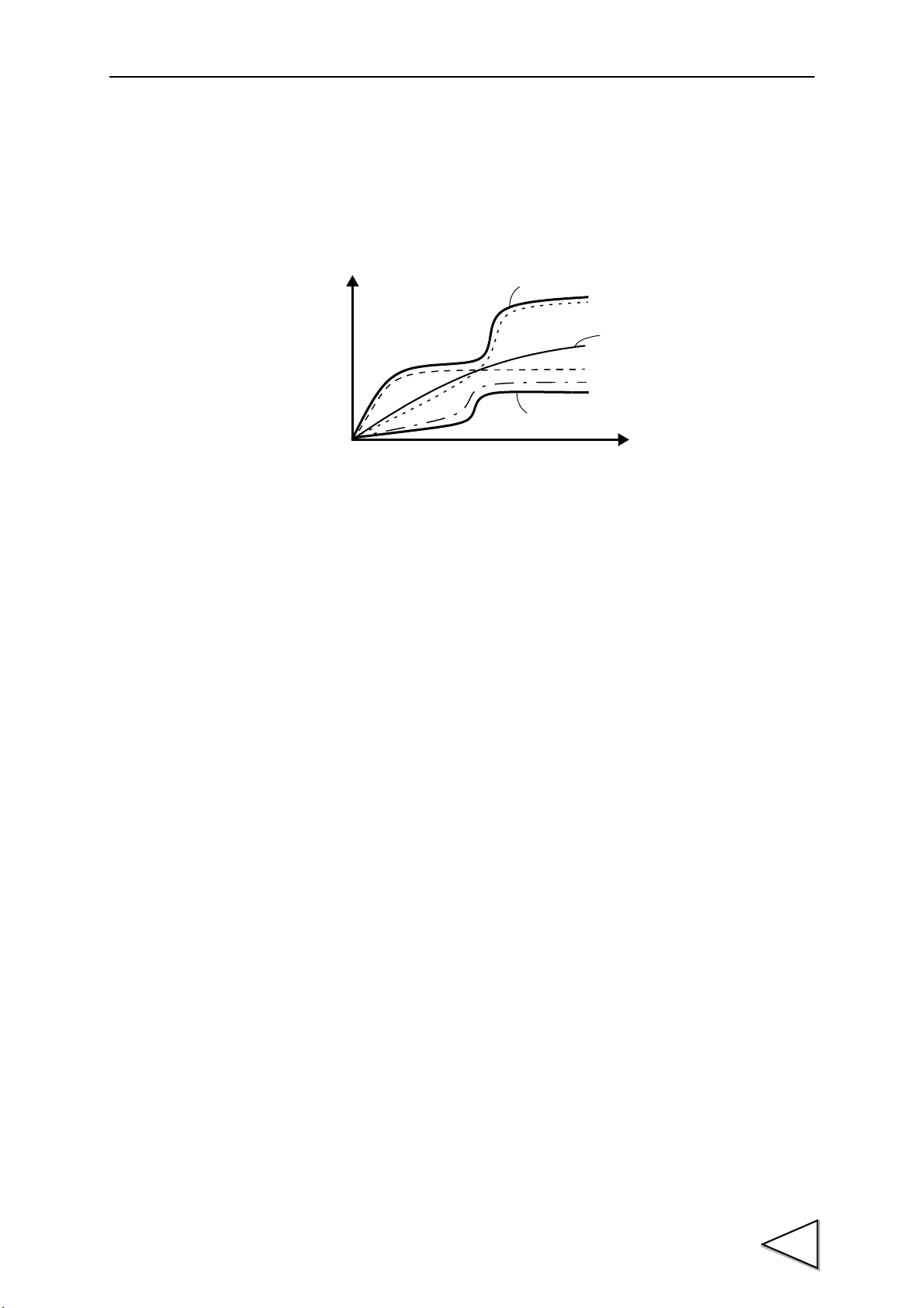
13.Waveform Comparison / Waveform and Displacement Comparison Mode
Example: Three samplings
Red line: High limit waveform
1st time
Blue line: Latest sampling waveform
3rd time
2nd time
Red line: Low limit
14. For repeating sampling to set the ranges of the High and Low Limits, repeat the
operations from 11. When two or more samplings are performed with the F395, the
upper limit of the waveforms obtained by sampling becomes the High Limit, and the
lower limit becomes the Low Limit.
15. Upon completion of sampling, set the area for High/Low Limit comparison under
"Area Setting". Set the start point / end point of the comparison area.
16. Edit the sampled waveform as necessary. Set the point under "Waveform Editing",
and rewrite the graph under "Select Edit". High and low limits can be set for the
waveform within the specified range in a unit of ± % or ± indicated value, and a
new waveform can also be made by drawing a line tying two points.
17. Register the waveform under "Waveform Save". Up to 16 sampled waveforms can be
saved from 0ch to 15ch, which can be used for high/low limit comparison by calling
with external selection signals.
18. The registered waveform can be called and edited again. The waveform called here
and edited as in 16 should be registered again as in 17.
72
Page 87

13.Waveform Comparison / Waveform and Displacement Comparison Mode
For the Un-passing Area Output setting, see "13-8. Un-passing Area
Output" P80.
Set whether or not to make
the OK output by the
Un-passing
Comparison area
The results are maintained.
Input waveform
High limit
Low limit
Start point
End point
Open CODE 16. (Do not use.)
Request
Control connector
13-4. Waveform Comparison Mode
In this mode, High/Low Limit Comparisons are made with waveforms changing with
time. High/Low Limit comparison values of approx.
2000 samplings can be stored per channel, so that sequential comparisons can be made in
the set area.
If the input waveform is within the range surrounded by the High and Low Limits, the
accept signal is output, and if the waveform is out of the range, the High or Low Limit
signal is output. (Red "+" mark display will result.)
Up to 16 pairs (ch) of High and Low Limit Waveforms can be stored, which can be
switched and controlled by external selection signals as desired.
When the results of measurement are displayed on the graph, the High and Low Limit
Waveforms are displayed only in the comparison area.
External selection signals
Input signals from the control connector on the rear panel. (See "4-3-2. Input and
Output Signals" P25.
73
Page 88

13.Waveform Comparison / Waveform and Displacement Comparison Mode
mm
High limit
Low limit
Load
Displacement
High/Low Limit Comparisons are made
as they are thinned out in this period.
Several samplings
13-5. Waveform and Displacement Comparison Mode
In this mode, High/Low Limit Comparisons are made with waveforms changing with
displacement. The operation is the same as in the Waveform Comparison mode.
However, since the X-axis is not a factor of time but input from a displacement sensor,
there are restrictions as follows:
13-5-1. Scale of the X-axis
The full scale of the X-axis is determined by the displacement value (mm, etc.) input by
Equivalent Input Calibration or Actual Load Calibration. (See the item P.37.) Inputs
greater than the above cannot be displayed. The internal resolution is approx. 1/2000.
Also, displacement input values are automatically digital-zeroed with a sampling start
under CAL. Protect when the Level Axis Select setting (See "16-2-9. Level Axis Select
/ Waveform Start Level / Waveform Termination Level / Hold Start Level" P113) is "Y-
axis". (See "6-4. Digital Zero" P39.)
13-5-2. Handling of Sudden Changes
In the case of sudden changes (9 counts or more) in the amount of displacement in the
one-time sampling interval, High/Low Limit comparisons are not made each time.
Comparisons are madeas they are thinned out in accordance with a specified rule.
As a result, the waveform may be displayed as follows:
74
Page 89
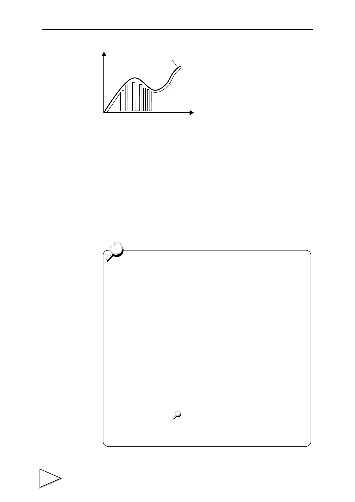
13.Waveform Comparison / Waveform and Displacement Comparison Mode
Actual input
Captured and
displayed
waveform
・ During sampling, displacement values are measured by peak hold.
Therefore, even if the displacement is restored, the measured value of
the peak point of displacement is processed. (Displacement values are
measured by valley hold during return measurements in the Hysteresis /
Hysteresis 2 mode.) When two or more samplings are performed at the
same displacement point, if any measured value is off the High/Low
Limit Waveform, the peak/valley value at that time is recorded (taken
later if off both the high and low limits), and if values are not off the
waveforms, the last measured value is recorded.
・Samplings with 0 or less displacement values are all processed as
displacement=0.
・Occurrence of thinning-out/ WARNING is shown by changing the color of
the displacement measured value display as follows (upper left of the
main screen). (Both return to normal conditions when the START signal
is input.)
Thinning-out ........Yellow
WARNING ..........Red
・ Sampling is terminated when the displacement value exceeds the full
scale value or the STOP signal is input. For the full scale value of
displacement, see the item P.37.
・When HI and LO are output by forced termination, judgment operation is
not performed
The "0" periods are thinned-out periods. The
wider the loss interval, the sharper a change
occurs. In this case, the WARNING signal is
output (turned on) through pin 48 of the
control connector due to a failure of a perfect
comparison with all data. Slow down the
displacement changing speed to prevent the
WARNING signal from being output. The
WARNING signal is cleared when the
START signal is input (turned on).
13-5-3. Updating the Amount of Displacement
If the amount of displacement is not updated for the number of samplings set under
Forced-Termination Limit (See "16-2-15. Forced-termination Limit" P120.), sampling is
terminated forcedly. At this time, HI and LO are also output simultaneously if the
Forced-Termination Output setting (See "16-2-16. Forced-termination Output" P120.) is
"ON".
75
Page 90
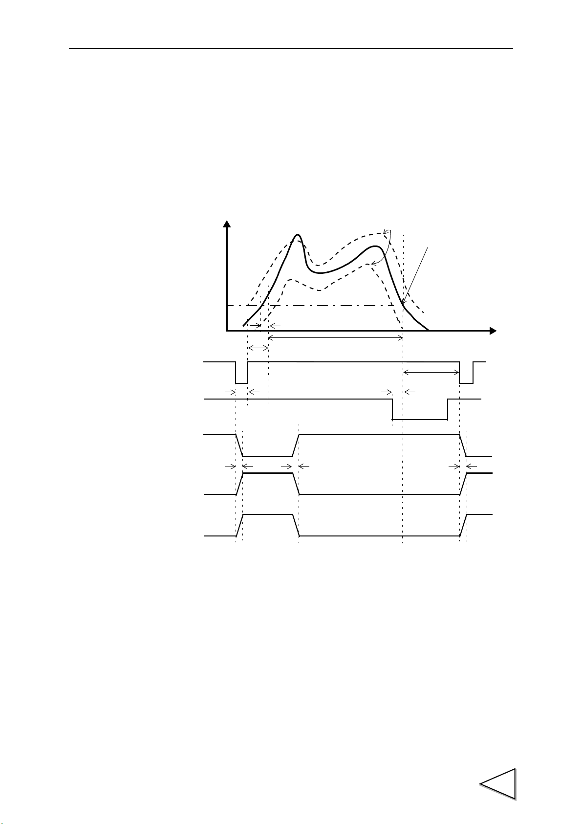
13.Waveform Comparison / Waveform and Displacement Comparison Mode
Comparison period
t
+
Judgment
t5
t1
t3
ON
ON
ON
Input waveform
t4
t2
START
Waveform Start Level
Next
Comparison waveforms
OFF
OFF
OFF
ON
STOP
OFF
(OK1)
ON
COMPLETE
OFF
t6 t7 t6
Example1 : In cace of NG
End of the comparison
area, inputting of the
STOP signal, excess of
2048 points, or crossing
over the waveform
termination level (when
the signal "Waveform
terminal level operation"
is ON)
Output
Judgment
(HI1)
Output
comparison
13-6. Timing in the Waveform Comparison /
Waveform and Displacement Comparison Mode
After the indicated value crosses over the Waveform Start Level, and the rising edge of
the START signal is input, when sampling enters the comparison area, waveform
comparison starts, and comparisons are made until the comparison area ends, or
waveform capturing is completed (See "9. Method of Starting Measurement" P43.)
Sampling is performed until inputting of the STOP signal, excess of 2048 points, or
crossing over the Waveform Terminal Level (when the signal "Waveform termination
level operation" is ON).
t1: Delay time between the instant when the indicated value exceeds the waveform start
level and the instant when the hold is detected. Ts msec (max.)
t2: Delay time between the instant when the START signal is input and the instant when
the comparison starts. Ts+0.8msec (max.)
t3: Minimum START signal width Ts+0.8msec (min.)
t4: Standby time to start the next comparison Approx. 300msec
t5: Delay time between the instant when the STOP signal is input and the instant when
the area ends Ts+0.8msec (max.)
t6: Delay time between the instant when the START signal is input and the instant when
the judgment output and COMPLETE change. Ts+1.6msec (max.)
t7: Delay time between the instant when NG occurs and the instant when the judgment
output and COMPLETE change. Ts+1.6msec (max.)
76
Page 91
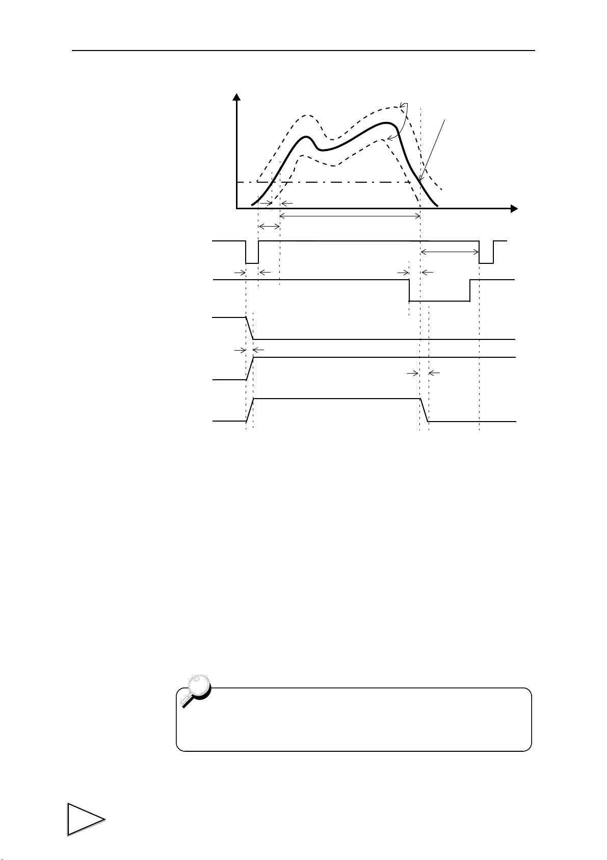
13.Waveform Comparison / Waveform and Displacement Comparison Mode
Comparison period
t
+
t5
t1
t3
ON
ON
ON
Input waveform
t4
t2
START
Waveform Start Level
Comparison waveforms
OFF
OFF
OFF
ON
STOP
OFF
(OK1)
ON
COMPLETE
OFF
t6
t7
(HI1, LO1)
Example2 : In cace of OK
Judgment
Output
Judgment
Output
Next
comparison
End of the comparison
area, inputting of the
STOP signal, excess of
2048 points, or crossing
over the waveform
termination level (when
the signal "Waveform
terminal level operation"
is ON)
The COMPLETE output turns OFF when the power is turned on and
reset operation, such as switching the operation ch, is performed.
t1: Delay time between the instant when the indicated value exceeds the waveform start
level and the instant when the hold is detected. Ts msec (max.)
t2: Delay time between the instant when the START signal is input and the instant when
the comparison starts. Ts+0.8msec (max.)
t3: Minimum START signal width Ts+0.8msec (min.)
t4: Standby time to start the next comparison Approx. 300msec
t5: Delay time between the instant when the STOP signal is input and the instant when
the area ends Ts+0.8msec (max.)
t6: Delay time between the instant when the START signal is input and the instant when
the judgment output and COMPLETE change. Ts+1.6msec (max.)
t7: Delay time between the instant when the comparison ends and the instant when
COMPLETE turns ON. 0.8ms (max.)
77
Page 92

13.Waveform Comparison / Waveform and Displacement Comparison Mode
A High/Low Limit Judgment is made with the hold point only when the
HI-HI/LO-LO Mode setting (See "16-2-7. High Limit / Low Limit / HI-HI/
LO-LO Mode / HI-HI Limit / LO-LO Limit" P109.) is "Hold". (If the setting
is "Sampling Value", real-time judgments on the sampling value will
result.)
START
T/H
STOP
COMPLETE
OFF
ON
OFF
ON
OFF
ON
OFF
ON
* For the delay time between each signal and processing, and the pulse width of each
signal, see "13-6. Timing in the Waveform Comparison / Waveform and Displacement
Comparison Mode" P76. Also, for the T/H signal and High/Low Limit Judgment output,
see "10-3-1. Sample Hold" P49, "10-3-2. Peak Hold" P50, and "10-3-3. Valley Hold" P51.
Hold reset
Waveform
Start Level
Detection/hold period and
waveform comparison period
Indicated value
Inputting of the STOP
signal, excess of 2048
points, or crossing over
the waveform
termination level (when
the signal "Waveform
terminal level operation"
is ON)
Sensor input value
13-7. Hold Operation
In the Waveform Comparison / Waveform and Displacement Comparison mode, any one
of hold operations: sample hold, peak hold, and valley hold can be executed
simultaneously. Simultaneously with the Waveform Comparison Judgment, a High/Low
Limit Judgment can also be made with the hold point.
13-7-1. Operation and Operating Method
Example:
When peak hold is executed
78
Page 93

13.Waveform Comparison / Waveform and Displacement Comparison Mode
・ Hold is detected over the period from the start to the end of sampling (at sampling-
time). Hold detection is performed only at sampling-time.
・ The hold detecting method is the same as in the Multi-Hold mode (using the T/H
signal).
・ The hold state is maintained even after completion of sampling by keeping the T/H
signal ON. (The hold can be cancelled by turning off the T/H signal.) Also, the hold is
reset by the timing of starting the next sampling even if the T/H signal is kept ON.
・ For High/Low Limit Judgment with the hold point, the HI-HI Limit / LO-LO Limit
setting is used, and the results of judgment is output to LO2/OK2/HI2. (For hold
operation and judgment of the hold point, the inhibit timer is effective.)
・ COMPLETE is output with respect to Waveform Comparison / Waveform and
Displacement Comparison. Therefore, check the results of Judgment of the hold point
at the end of sampling and by the timing of turning off the T/H signal.
・ The hold point is displayed with an orange "+" mark on the graph (the last one point
only). HI-HI Limit and LO-LO Limit lines are not displayed.
・ By turning on the input "Display after measurement", the last sampling value is held
even without hold operation, but no "+" mark is displayed on the graph.
・ When hold operation is not performed, real-time High/Low Limit Judgments are made
on the sampling value with the HI-HI Limit / LO-LO Limit.
・ For details of the main screen, and waveform reading / rejected waveform reading
screen, see "2-1-1. Touch Panel Type Color Liquid Crystal Display" P7.
79
Page 94
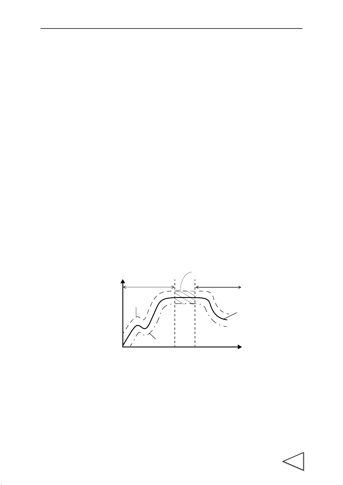
13.Waveform Comparison / Waveform and Displacement Comparison Mode
Always acceptable
The results are maintained.
Comparison area
Input waveform
Start point
End point
High limit
Low limit
When the setting is "ON"
13-7-2. Setting Method
1. Set "Channel Number Selection" in "Code Setting" to the same operation ch as used
for measurement.
2. Set the HI-HI Limit / LO-LO Limit judgment to "Hold". (If set at "Sampling ", real-
time Judgments on the sampling value will result.)
3. Set the hold to any of "Sample Hold", "Peak Hold" and "Valley Hold". If the hold is
set at "None", real-time High/Low Limit Judgments on the sampling value with the
HI-HI Limit / LO-LO Limit will result.
4. For High/Low Limit Judgment of the hold point, set the HI-HI Limit / LO-LO Limit.
(See "16-2-7. High Limit / Low Limit / HI-HI/LO-LO Mode / HI-HI Limit / LO-LO
Limit" P109.)
13-8. Un-passing Area Output
If the Un-passing Area Output setting (See "16-2-17. Un-passing Area Output" P120.) is
"OFF", the OK signal is not output when sampling does not pass the comparison area.
Since the judgment output is not made until sampling enters the comparison area in this
case, if it ends in an un-passing state, all of the HI, OK and LO outputs are turned off.
80
Page 95

13.Waveform Comparison / Waveform and Displacement Comparison Mode
When the setting is "OFF"
・ The result of the previous judgment is cleared when the START
signal is turned on.
・ No output will also result if sampling starts after the end point.
When the setting is "OFF"
Nothing is output.
Comparison area
The results are maintained.
Input waveform
High limit
Low limit
Start point End point
13-9. Display After Measurement
Measurement display upon completion of comparison can be selected by the input
"Display after measurement" from the following.
(See "4-3-2. Input and Output Signals" P25.)
1. Input "Display after measurement" ON: The last value is held.
(The held value is canceled when the next sampling starts.)
2. Input "Display after measurement" OFF: Real-time display.
81
Page 96

14. Waveform Editing
MODE → Wave Sampling → Wave Call
No pass/fail judgment can be made on the waveform as it is called up
here. For making a judgment, the waveform should be stored under
"14-4-4. Waveform Save" P91, and further the ch should be input
externally (See "13-3. Waveform Sampling Procedures" P69.)
MODE → Wave Sampling → Clear
High limit waveform: Set to -9999 (Not including the decimal point.)
Low limit waveform: Set to 9999 (Not including the decimal point.)
The operation is executed by pressing the key.
The waveform data for comparison from channel 0 to 15 that
have been registered inside is not cleared.
14-1. Waveform Call-up
Stored waveforms are called up for editing by this operation. Waveforms are stored
under "14-4-4. Waveform Save" P91, and edited under "14-4. Waveform Editing" P84.
Setting range: 0 ~ 15
After call-up, go to the waveform editing screen to display the called-up waveform.
14.Waveform Editing
14-2. Waveform Clear
Waveform data for waveform sampling that have been temporarily registered inside is
cleared by this operation. Before sampling waveforms, be sure to execute this operation.
82
Page 97

14.Waveform Editing
MODE → Wave Sampling → Sampling
* For the waveform operation
keys, see "14-4. Waveform
Editing" P84.
Waveform sampling start key Waveform selection execution key
Temporarily registered waveform data cannot be used in the Waveform
Comparison mode as it is, and is also cleared when the power is
turned off.
By storing waveforms under "Waveform Save" (See "14-4-4.
Waveform Save" P91.), these can be used in the Waveform
Comparison mode, and are also backed up.
14-3. Waveform Sampling
Waveforms are sampled by this operation. Before this operation, be sure to execute
"Waveform Clear".
1. Press the key ("SAMP" is displayed on the left side of the screen.), and
start sampling by the procedures in "9. Method of Starting Measurement" P43. (The
sampling status is displayed at the top of the Y-axis display.)
2. After waveform sampling, display the sampled waveform. Confirm the waveform by
using the waveform operation keys.
3. Select whether or not to use this waveform. To use, press the key.
The waveform obtained by sampling is registered temporarily. When not using this
waveform, start the next sampling.
4. For performing two or more samplings, repeat "1." to "3." For ending the sampling,
press the key or key.
: To the area setting screen.
: To each item selection screen for waveform sampling.
83
Page 98
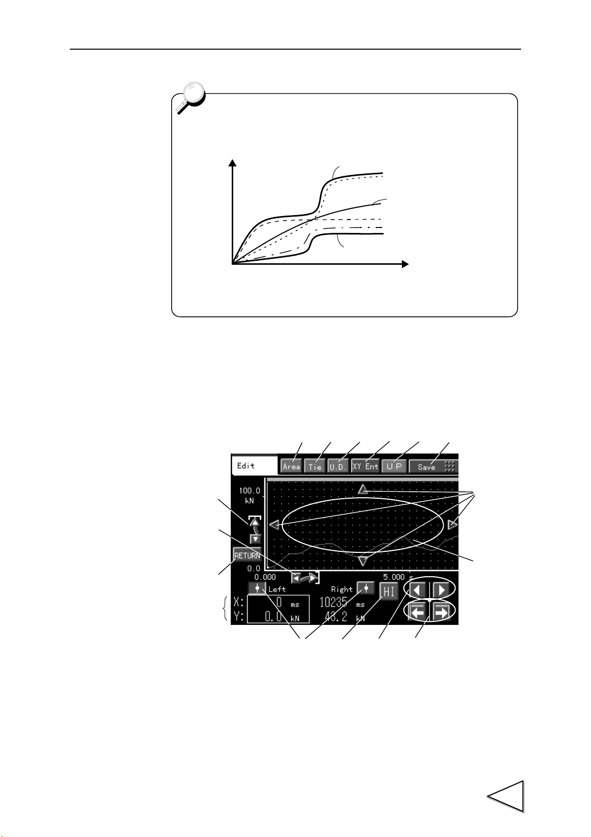
14.Waveform Editing
・When two or more samplings are performed, the upper limit
and lower limit of the waveforms obtained by sampling are
registered as the high limit and low limit, respectively.
・ When waveform sampling is executed, OK is output as a
judgment result without performing judgment operation (when
"SAMP" is displayed).
Example: 4th samplings
Red line: High limit waveform
Red line: Low limit
1st time
3rd time
2nd time
Blue line: Latest sampling waveform
(4th time)
②③④⑤⑥
⑦
⑨
⑩
⑭
⑪⑫⑬
⑯
①
⑮
⑧
14-4. Waveform Editing
Confirm or edit a waveform on this screen. The waveform can be edited by area setting,
tie drawing, and shifting, and the waveform can be registered by waveform save. Also,
the waveform can be confirmed by scrolling, scaling up/down, and moving the cursor.
1. Area setting key - - - - - - - - - Goes to the area setting screen.
2. Tie drawing key - - - - - - - - - Goes to the tie drawing screen.
3. Shift key - - - - - - - - - - - - - - Goes to the shift screen.
(See "14-4-3. Area Setting" P90.)
(See "14-4-1. Tie Drawing" P86.)
(See "14-4-2. Shift" P89.)
84
Page 99

14.Waveform Editing
Temporarily registered waveform data cannot be used in the Waveform
Comparison mode as it is, and is also cleared when the power is
turned off.
By storing waveforms under "Waveform Save" (See "14-4-4.
Waveform Save" P91.), these can be used in the Waveform
Comparison mode, and are also backed up.
4. Axis register key - - - - - - - - - Carries out axis registration.
Changes the set value of the Y-axis start point / Y-axis
scaling / X-axis start point / X-axis scaling according
to the display.
Since the graph is first displayed on the screen by the
registered axis setting, the influence of changing the
axis setting by waveform reading or editing is
eliminated.
5. UP key - - - - - - - - - - - - - - - Goes to the waveform sampling item selection screen.
6. Waveform save key - - - - - - - Goes to the waveform save screen.
(See "14-4-4. Waveform Save" P91.)
7. Y-axis scaling up/down key- - Scales up/down in the Y-axis direction on the basis of
the Y-axis start point.
8. X-axis scaling up/down key - Scales up/down in the X-axis direction on the basis of
the X-axis start point.
9. Axis return key - - - - - - - - - - Returns the axis setting as registered.
10. Cursor change keys - - - - - - Changes the cursor between the right and left.
The selected cursor becomes white, and the reading is
also displayed in white. The reading is enclosed with a
box.
11. High/low limit waveform change key- - - Changes the selected waveform to a high/low limit
waveform.
12. Cursor right/left key - - - - - - Moves the cursor in the X-axis direction dot by dot.
13. Area head/end key - - - - - - - Moves the cursor to the head/end of the area.
14. Screen move keys - - - - - - - Moves the screen on the X-axis by 1/8 of the distance
between the start point and end point of the graph, and
on the Y-axis by 1/4 of the distance between the start
point and end point of the graph.
If you keep pressing the key, continuous movement
will result.
15. Graph area - - - - - - - - - - - - Moves the cursor to the pressed location in the graph
area.
Those other than the screen move keys enter into the
cursor moving area.
16. Reading display- - - - - - - - - Displays the cursor reading.
One of on the right side of the numerical value
shows 0.25 (decimals).
85
Page 100
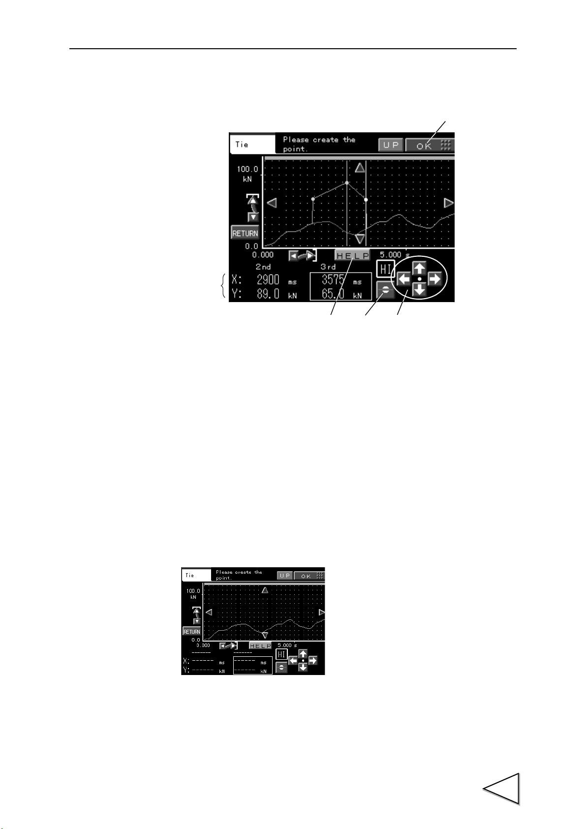
14-4-1. Tie Drawing
①
②⑤
③
④
Prepare points by touching the graph area, and tie the points to create a waveform.
14.Waveform Editing
1. Drawing OK key - - - - - - - - - Determines the created waveform.
2. Help key - - - - - - - - - - - - - - Changes the display in the character display area to
3. Character display area - - - - - Displays the reading or help.
Reading display - - - : Displays the ongoing point in white.
Help display - - - - - : Gives a brief description of the operating procedure.
4. Point wave key - - - - - - - - - - Moves the ongoing point to the original waveform.
5. Point + key- - - - - - - - - - - - - Can finely adjust the ongoing point.
14-4-1-1. Tie Drawing Procedures
1. Touch the graph area at which you want to prepare the first point.
reading display or help display.
Displays the previous point in blue.
86
 Loading...