

Page 1

F381A/F388A
CC-Link I/F
OPERATION MANUAL
01FEB2015REV.3.01
「CC-Link Ver.1.10」
Page 2

Introduction
Introduction
This document describes the standard specifications of the CC-Link I/F that links a PLC and F381A/
F388A.
By using the CC-Link I/F, the F381A/F388A can be controlled directly from the PLC, so that wiring can
be substantially reduced.
Readers this document should have basic knowledge of the programming of the PLC and basic knowledge
of the CC-Link I/F.
The F381A/F388A with CC-Link I/F can be linked with general-purpose PLC as a remote device station
corresponding to the CC-Link Ver. 1.10.
(CC-Link is an abbreviation for Control & Communication Link.)
Functions provided by the F381A/F388A CC-Link
● Setting of wave No.
Wave No. can be assigned.
It can be changed by inputting a set value, and turning on the relay of Request flag 1.
(See "●Setting change of wave No."on p.5.)
● For changing the current set value
The setting can be changed by using the general-purpose area "data".
It can be changed by inputting the setting item (command) and a set value, and turning on the relay of
Request flag 2. (The R/W relay should be off.)
(See "●Setting change by using the general-purpose area "data""on p.6.)
Note
) Items that can be changed are only those entered in the "Command list" on p.11.
● For checking the current set value
The set value can be read by using the general-purpose area "data".
It can be read by inputting the setting item (command), and turning on the relay of Request flag 2.
(The R/W relay should be on.)
(See "●Request to read set value(s) by using the general-purpose area "data""on p.7.)
Note
) Items that can be read are only those entered in the "Command list" on p.11.
● Display of indicated values, hold values and wave No.
The remote register R → M (F381/F388→ PLC) allows display of indicated values, hold values and wave
No. (See"Remote resister R → M (F381A/F388A → PLC)"on p.7.)
The indicated values are updated at approx. 200Hz, and the hold values are updated after completion of
sampling.
Note
) Start the next sampling after completion of updating.
● About status information
Status information on the same items as I/O can be obtained.
The status information is displayed in the relay domain of the remote station.
(See "Remote input (F381A/F388A → PLC)" on p.19.)
● About direction of operations
Operations on the same items as I/O can be directed by using the relay domain.
Turn on/off the corresponding bit in the relay domain.
(See "Remote output (PLC → F381A/F388A)" on p.17.)
I
Page 3

Contents
Contents
1. Part names. . . . . . . . . . . . . . . . . . . . . . . . . . . . . . . . . . . . . . . . . . . . . . . . . . . 1
2. F381A/F388A setting . . . . . . . . . . . . . . . . . . . . . . . . . . . . . . . . . . . . . . . . . . . 1
3. Communication connector . . . . . . . . . . . . . . . . . . . . . . . . . . . . . . . . . . . . . . . 3
4. Status LED. . . . . . . . . . . . . . . . . . . . . . . . . . . . . . . . . . . . . . . . . . . . . . . . . . . 4
5. PLC address . . . . . . . . . . . . . . . . . . . . . . . . . . . . . . . . . . . . . . . . . . . . . . . . . 4
6. Address map . . . . . . . . . . . . . . . . . . . . . . . . . . . . . . . . . . . . . . . . . . . . . . . . . 4
■ Data domain . . . . . . . . . . . . . . . . . . . . . . . . . . . . . . . . . . . . . . . . . . . . . . . . . . . . . . . . . . .4
■ Unit setting list . . . . . . . . . . . . . . . . . . . . . . . . . . . . . . . . . . . . . . . . . . . . . . . . . . . . . . . .15
■ About remote input/output . . . . . . . . . . . . . . . . . . . . . . . . . . . . . . . . . . . . . . . . . . . . . . . 17
■ Relay domain . . . . . . . . . . . . . . . . . . . . . . . . . . . . . . . . . . . . . . . . . . . . . . . . . . . . . . . . . 17
7. Setting procedure. . . . . . . . . . . . . . . . . . . . . . . . . . . . . . . . . . . . . . . . . . . . . 21
■ Setting of wave No. by using Request flag 1 . . . . . . . . . . . . . . . . . . . . . . . . . . . . . . . . . 21
■ Setting by using the general-purpose area "data" and "command",
and Request flag 2 . . . . . . . . . . . . . . . . . . . . . . . . . . . . . . . . . . . . . . . . . . . . . . . . . . . . . 21
■ Reading set value(s). . . . . . . . . . . . . . . . . . . . . . . . . . . . . . . . . . . . . . . . . . . . . . . . . . . . 22
■ Sample of ladder program . . . . . . . . . . . . . . . . . . . . . . . . . . . . . . . . . . . . . . . . . . . . . . . 22
8. Outside dimensions . . . . . . . . . . . . . . . . . . . . . . . . . . . . . . . . . . . . . . . . . . . 26
II
Page 4

1. Part names
Operation
Status LED
Communication
connector
When the above setting is changed, the communications between the F381A/
F388A and PLC are reset so that the ones stop momentarily.
Point
Status LED
Displays the status of communication.
(See "4.Status LED" on p.4.)
Communication connector
Connector for CC-Link interface.
(See "3.Communication connector" on p.3.)
2. F381A/F388A setting
1.Part names
Main screen→Setting→First Setting→Option setting→CC-Link
Baud rate (Initial value, 10M): 156k, 625k, 2.5M, 5M, 10M
Station No. (Initial value, No.1): No.1 to 61
Input select 1 (Initial value, Ext.input): Network, Ext.input
Input select 2 (Initial value, Ext.input): Network, Ext.input
Explanation for setting
Baud rate : Deciding network speed
Station No. : Setting slave station number
Input select1 to 2 : Select whether input signals of the F381A/F388A are directed by the
control connector (Ext. input) or by CC-Link (Network). For each setting,
select the following signal.
Input select 1..........Load Digital Zero, DPM Positioning, Start, Stop, Hold, Reset, Backlight
On, Prohibit Touch Panel
Input select 2..........Work 1, Work 2, Work 4, Work 8
* The number of stations occupied is fixed at 4.
1
Page 5

2.F381A/F388A setting
0: Normal 1: Error
0: Normal 1: Error (Changed from the power-on-time setting)
0: Normal 1: Error (Changed from the power-on-time setting)
Station No. switch setting error
0: Normal 1: Error
Baud rate switch setting error
Station No. setting switch change error
Baud rate switch change error
0: Normal 1: CRC Error
0: Normal 1: Error
CRC error
Time over error
0: Normal 1: Time over error
Channel carrier detection
0: Sufficient 1: Not sufficient for the station
0: Sufficient 1: Not sufficient for the station
Y data or RWw data error
0: Sufficient 1: Not sufficient for the station
Y data error
RWw data error
Settings of Mitsubishi (general-purpose) PLC CPU unit.
When you use Mitsubishi (general-purpose) PLC MELSEC-Q series, set up master
station network parameters as follows.
・CC-Link mode setting: Remote net Ver. 1 mode.
・Station type: Remote device station
(Station information settings → Station type)
・Occupied station: 4 station
Point
Alarm codes
At the lower right of the CC-Link setting screen, communication
conditions and PLC CPU status are displayed.
Code Status
Alarm code 1 0 0 0 0
Alarm code 2 0 0 0
Alarm code 3 0 0 0
PLC CPU STOP / RUN Displays the PLC CPU status (STOP or RUN).
--- / ERR Displays "---" when the PLC CPU is normal, and "ERR"
when it is abnormal.
2
Page 6

3. Communication connector
Name Signal type
DA Signal line DA side
DB Signal line DB side
DG Signal line Ground
SLD Shield
FG Frame Ground
・Pick up the plug and operate the lever with a thumb.
・For the protection from the damage, do not operate
the lever without removing the plug.
When the F381A/F388A is a unit at both ends, terminator resistance must be
installed. (Confirm with the CC-Link specifications.) At this time, when the DA and
DB signal lines and resistance are to be connected to the connector, be aware
that poor contact may result if the nipping conditions differ between the leg of the
resistance and signal lines. There is a possibility of abnormal operation.
Attention
SLD and FG are connected inside.
Suitable plug for the connection is the Plug made by WAGO CO., Ltd. or equivalent one. (Accessories)
CAUTION
3.Communication connector
3
Page 7

4.Status LED
4. Status LED
LED expresses the Status of Communication.
LED Light ON Light OFF Blinks
RUN
SD
RD
ERR
5. PLC address
The F381A/F388A is the remote device stations (occupies four fixed stations).
Prevent overlapping addresses.
At the master station, the addresses assigned to the remote stations changes according to Station No.
・Normal ・Reset Action
・No Communication
・Transmitting ----- -----
・Receiving ----- -----
・Setting Error
・CRC Error
・Fault
・Normal
-----
-----
Station No.
1
2
3
Therefore, the address data of the F381A/F388A also changes according to Station No.
The following address map is in the state of Station No.1.
Remote
RX0000 RY0000 RWw0000 RWr0000
00E0H 0160H 01E0H 02E0H
RX0020 RY0020 RWw0004 RWr0004
00E2H 0162H 01E4H 02E4H
RX0040 RY0040 RWw0008 RWr0008
00E4H 0164H 01E8H 02E8H
6. Address map
■Data domain
Remote resister M → R (PLC → F381A/F388A)
Use the remote register M → R (PLC → F381A/F388A) for the following purposes.
・『Setting change of wave No.』(See p.5)
・『Setting change by using the general-purpose area "data"』(See p.6)
・『Request to read set value(s) by using the general-purpose area "data"』(See p.7)
input
Remote
output
Remote resister
M→R R→M
4
Page 8

6.Address map
Using
Request flag 2
Using
Request flag 1
Station
1
2
3
4
Buffer
Address
01E0H RWw0000
01E1H RWw0001
01E2H RWw0002
01E3H RWw0003
01E4H RWw0004
01E5H RWw0005
01E6H RWw0006
01E7H RWw0007
01E8H RWw0008
01E9H RWw0009
01EAH RWw000A
01EBH RWw000B
01ECH RWw000C
01EDH RWw000D
01EEH RWw000E
01EFH RWw000F
Device
M→R
Content
MSB LSB
Unused
16bit
Unused
16bit
Wave No.
Wave No.
Wave No.
General-
purpose
area
1st byte
8bit
3rd byte
8bit
5th byte
8bit
7th byte
8bit
9th byte
8bit
11th byte
8bit
13th byte
8bit
15th byte
8bit
17th byte
8bit
19th byte
8bit
Section No.
8bit
Command
2nd byte
8bit
4th byte
8bit
6th byte
8bit
8th byte
8bit
10th byte
8bit
12th byte
8bit
14th byte
8bit
16th byte
8bit
18th byte
8bit
20th byte
8bit
Work No.
8bit
16bit
Data
32bit
L
H
Explanation for remote resister M → R
● Setting change of wave No.
Use for setting wave No. (Request flag 1)
Setting range: ASCII code (20 to 7E), Shifted JIS code (80 to FCH)
* How to write wave No.
1. Input wave No. to the address for 20 bytes so that the first byte becomes Hi byte.
* Input 20H to unused bytes.
2. Change the remote output "Request flag 1"
3. After checking that the remote input "Response 1"
(*1)
from 0 to 1.
(*2)
changes from 0 to 1, change
the remote output "Request flag 1" from 1 to 0.
4. Set the remote output "RM data change" to 1.
5. Check that the specified wave No. is stored in the remote register "wave No."
(response)
(*3)
.
5
Page 9

6.Address map
・If a value exceeding the setting range is input, the setting is not changed.
・Set values should be two’s-complement.
Input a negative set value as follows:
Example: Inputting -1234
Decimal number : -1234
Hexadecimal digit : 65536 - 1234 = 64302 = FB2E(H)
・For checking the changed value after a setting change, make a request to read
set value(s) by using the general-purpose area "data". (See p.7)
Point
● Setting change by using the general-purpose area "data"
* How to write set value(s)
*1: See "Remote output (PLC → F381A/F388A)"on p.17.
*2: See "Remote input (F381A/F388A → PLC)"on p.19.
*3: See "Remote resister R → M (F381A/F388A → PLC)"on p.7.
For changing any setting, use the general-purpose area "data". General-purpose area
"command" and general-purpose area "data" comprise one set. Input the command
setting item you want to change to the general-purpose area "command", and input a set value in
the general-purpose area "data". By turning off R/W
relay of Request flag 2
(*2)
, the input setting is written in the F381A/F388A.
(*2)
in the relay domain and turning on the
(*1)
of the
1. Input the command of the set value to write to the general-purpose area "command."
2. Input the work No. to write to the general-purpose area "work No."
Range: 0 to 15
3. Input the section to write to the general-purpose area "section No."
Range: 1 to 5
4. Set the remote output "R/W" to 0.
5. Input the value to write to the general-purpose area "data."
6. Change the remote output "Request flag 2"
7. After checking that the remote input "Response 2"
the remote output "Request flag 2"
(*2)
8. The response is stored in the remote input "R/W" (response)
purpose area (response)
(*4)
.
9. Check the contents of the general-purpose area (response)
*1
: See "Command list"on p.11.
*2: See "Remote output (PLC → F381A/F388A)"on p.17.
*3: See "Remote input (F381A/F388A → PLC)"on p.19.
*4: See "Remote resister R → M (F381A/F388A → PLC)"on p.7.
* If any number not in the command list is set to the general-purpose area "command",
Response 2 will turn on, but FFFFH is written in the general-purpose area "command"
(response).
(*2)
from 0 to 1.
from 1 to 0.
(*3)
changes from 0 to 1, change
(*3)
and general-
(*4)
.
6
Page 10

6.Address map
● Request to read set value(s) by using the general-purpose area "data"
For reading any set value, use the general-purpose area "data". General-purpose area
"command" and general-purpose area "data" comprise one set. Input the command
setting item you want to read to the general-purpose area "command". By turning on R/W
the relay domain and turning on the relay of Request flag 2
specified by the general-purpose area "command" is replied to the general-purpose area
(response). Upon receipt of the reply, Response 2
* How to read set value(s)
(*3)
turns on.
(*2)
, the set value of the item
(*1)
1. Input the command of the set value to read to the general-purpose area
"command."
2. Input the work No. to read to the general-purpose area "work No."
Range: 0 to 15
3. Input the section to read to the general-purpose area "section No."
Range: 1 to 5
4. Set the remote output "R/W" to 1.
of the
(*2)
in
5. Change the remote output "Request flag 2"
6. After checking that the remote input "Response 2"
the remote output "Request flag 2"
(*2)
7. The response is stored in the remote input "R/W" (response)
purpose area (response)
(*4)
.
8. Check the contents of the general-purpose area (response)
*1
: See "Command list"on p.11.
*2: See "Remote output (PLC → F381A/F388A)"on p.17.
*3: See "Remote input (F381A/F388A → PLC)"on p.19.
*4: See "Remote resister R → M (F381A/F388A → PLC)"on p.7.
* If any number not in the command list is set to the general-purpose area "command",
Response 2 will turn on, but FFFFH is written in the general-purpose area "command"
(response).
General-purpose area "data"
General-purpose area "command"
Use for a setting change and setting readout by using the general-purpose data area.
(See "Command list"on p.11.)
(*2)
from 0 to 1.
from 1 to 0.
(*3)
changes from 0 to 1, change
(*3)
and general-
(*4)
.
Remote resister R → M (F381A/F388A → PLC)
Use the remote register R → M (F381A/F388A → PLC) for the following purposes.
・『Setting change by using the general-purpose area "data"』(See p.6)
・『Request to read set value(s) by using the general-purpose area "data"』(See p.7)
Measurement values are displayed on an item-by-item basis.
(See "Explanation for remote resister R → M"on p.9.)
7
Page 11

6.Address map
Data changes
according to
the remote
output "RM
data change"
・When the remote output "RM data change" is OFF
Stat ion
1
2
3
4
Buffer
Address
02E0H RWr0000
02E1H RWr0001
02E2H RWr0002
02E3H RWr0003
02E4H RWr0004
02E5H RWr0005
02E6H RWr0006
02E7H RWr0007
02E8H RWr0008
02E9H RWr0009
02EAH RWr000A
02EBH RWr000B
02ECH RWr000C
02EDH RWr000D
02EEH RWr000E
02EFH RWr000F
Device
R→M
Content
MSB LSB
Load
Present
value
Displacement (0 for time)
16bit
16bit
Load
Section 1
Displacement (Time)
16bit
16bit
Load
Section 2
Displacement (Time)
16bit
16bit
Load
Section 3
Displacement (Time)
16bit
16bit
Load
Section 4
Displacement (Time)
16bit
16bit
Load
Section 5
Displacement (Time)
16bit
16bit
* Presence or absence of valid hold data
16bit
Command
16bit
General-
purpose area
(response)
Data
32bit
L
H
8
Page 12

Stat ion
Data changes
according to
the remote
output "RM
data change"
1
2
3
4
・When the remote output "RM data change" is ON
Buffer
Address
02E0H RWr0000
02E1H RWr0001
02E2H RWr0002
02E3H RWr0003
02E4H RWr0004
02E5H RWr0005
02E6H RWr0006
02E7H RWr0007
02E8H RWr0008
02E9H RWr0009
02EAH RWr000A
02EBH RWr000B
02ECH RWr000C
02EDH RWr000D
02EEH RWr000E
02EFH RWr000F
Device
R→M
MSB LSB
Present
value
Wave No.
(
response)
Wave No.
response)
(
Wave No.
response)
(
* Presence or absence of hold value
General-
purpose area
(response)
Content
Displacement (0 for time)
1st byte
3rd byte
5th byte
7th byte
9th byte
11th byte
13th byte
15th byte
17th byte
19th byte
Load
8bit
8bit
8bit
8bit
8bit
8bit
8bit
8bit
8bit
8bit
Command
Data
6.Address map
16bit
16bit
2nd byte
8bit
4th byte
8bit
6th byte
8bit
8th byte
8bit
10th byte
8bit
12th byte
8bit
14th byte
8bit
16th byte
8bit
18th byte
8bit
20th byte
8bit
16bit
16bit
L
H
32bit
Explanation for remote resister R → M
● Present value
The currently indicated value (displacement, time) data is stored. If the indicated value is held,
the hold value is displayed.
* If the X-axis of the waveform represents time, the value of displacement becomes 0.
Range Load: -9999 to 9999, Displacement: -9999 to 32000
● Section1 to Section5
These are valid when the remote output "RM data change" is 0.
Hold value(s) (load, time or displacement) of Section1 to Section5 is stored.
If there is any valid hold value in a section, "1" is stored in the bit of "Presence or absence of
hold value." If there is no valid hold value, "0" is stored in the bit of "Presence or absence of
hold value," and "0" is stored in the hold value.
Range Load: -9999 to 9999, Time: 0 to 51175 (ms), Displacement: -9999 to 32000
9
Page 13

6.Address map
Under the following conditions, the specified command is not accepted, but FFFFH is
written in the general-purpose area "command" (response).
Setting change
・Made during measurement
・With the general-purpose area "data" outside the input range
・With no setting item corresponding to the general-purpose area "command"
・With the general-purpose area "section No." or "work No." outside the input range
Setting read
・With no setting item corresponding to the general-purpose area "command"
・With the general-purpose area "section No." or "work No." outside the input range
Point
* How to read a hold value
● Wave No.
● Presence or absence of hold value
1. Check that the remote input "Complete" has changed from 0 to 1.
2. Set the remote output "RM data change" to 0.
3. Check that there is a valid hold value in the section you want to read by "Presence
or absence of hold value", and if any, read the hold value.
This is valid when the remote output "RM data change" is 1.
The currently-set wave No. is stored.
If there is valid data for the hold value in a section, "1" is stored in the bit corresponding to each
section. If there is no valid data, "0" is stored in the bit corresponding to each section, and "0" is
stored in the hold value.
・Presence or absence of hold value
Bit Corresponding section Bit Corresponding section
B0 Section1 B10
B1 Section2 B11
B2 Section3 B12
B3 Section4 B13
B4 Section5 B14
B5 B15
B6
B7
B8
B9
● General-purpose area "command" (response)
When setting is updated or set value(s) is read by using the general-purpose area "data", the
specified general-purpose area "command" is written in the general-purpose area "command"
(response).
● General-purpose area "data" (response)
When set value(s) is read by using the general-purpose area "data", the read set value(s) is
written.
10
Page 14

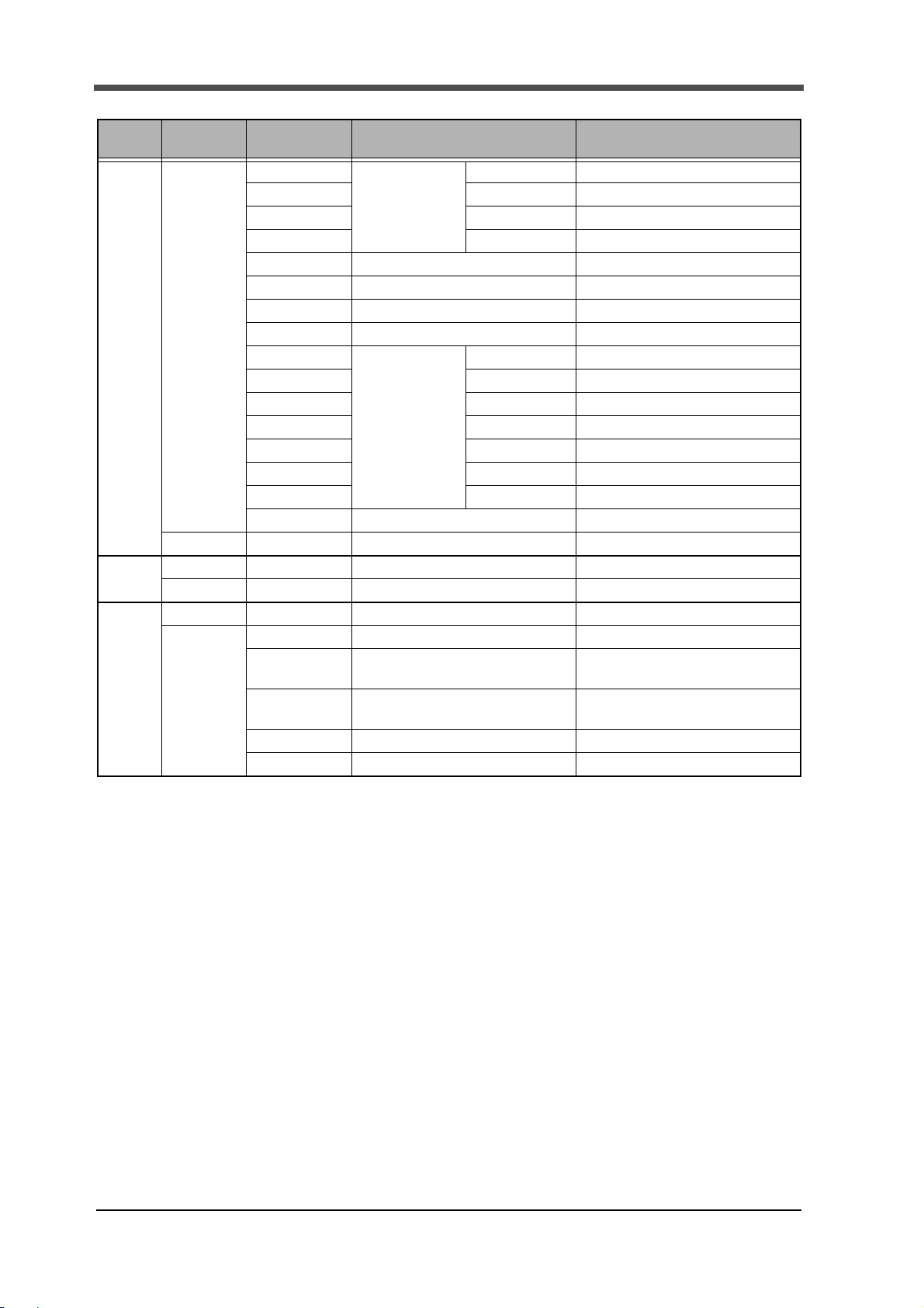
Command list
( ① F381A ② F388A)
6.Address map
Classification of items Setting item
First
Setting
Y-ax is
Setting
X-axis
Setting
(Displacement)
Communication
Setting
①Exc. Voltage
②Input Select
Unit 101
Decimal Place 102 0: 0 1: 0.0 2: 0.00 3: 0.000
Equiv. Cal.
(rated output)
Equiv. Cal.
(rated capacity)
Overload 106 0 to 9999
Increment 107 0: 1 1: 2 2: 5 3: 10
Analog Filter 108
Digital Filter 109 0, 2 to 999 [Times]
DZ Limit 110 0 to 9999
Time/DPM Change 200 0: Time 1: Displacement
Phase Select 201 0: A/B-Phase 1: Only A-Phase
Wave Reference 202 0: Front 1: Back
Unit 203
Decimal Place 204 0: 0 1: 0.0 2: 0.00 3: 0.000
Equiv. Cal.
(number of pulses)
(voltage value)
Equiv. Cal.
(displacement value)
Measure Length 208 Time/Displacement Change; Time
DPM Positioning 209 -9999 to 32000
Analog Filter
(Only ①)
Digital Filter 211 0, 2 to 999 [Times]
Speed 300 0: 1200 1: 2400 2: 4800
Data Bit 301
Parity Bit 302 0: None 1: Even 2: Odd
Stop Bit 303
Delimiter 304 0: CR 1: CR+LF
Header 305 0: None 1: STX
Flow Control 306 0: Off 1: RTS/CTS Control
Com. Mode 307 0: Normal 1: Hold Point Mode
Command
(RWw000D)
100
104
105 -9999 to 9999
206 Standard
207 -99999 to 99999
210
Data area input (output at read-time) range
①0: 2.5 1: 10 [V]
②0: ±10V 1: ±20mA
See "■Unit setting list" on page 15.
①-9.999 to 9.999 [mV/V]
②-99.99 to 99.99 [V, mA]
0: 10 1: 30 2: 100 3: 300 [Hz]
See "■Unit setting list" on page 15.
1 to 1000000
When the voltage input option is used
-9.999 to 9.999 [V] (Only ①)
0: 0.5 1: 1.0 2: 2.0 3: 5.0 4: 10.0 [s]
Time/Displacement Change; Displacement
0: 2000 1: 4000 2: 6000
3: 8000 4: 10000
0: 10 1: 30 2: 100 3: 300 [Hz]
3: 9600 4: 19.2k 5: 38.4k [bps]
0: 7 1: 8 [bit]
0: 1 1: 2 [bit]
(Input:RWw000E to 000F)
(Output:RWr000E to 000F)
11
Page 15

6.Address map
Classification of items Setting item
First
Setting
Settings
by
work
[Work
0 to 15]
System
Setting
Measurement
Start
Condition
Setting
Display
Range
Setting
Backlight
(ON Time)
Language 401 0: Japanese 1: English
Work Protect 402 0: Not Protect 1: Protect
First Protect 403 0: Not Protect 1: Protect
Undefined 404 100 to 170
Backlight
(Bright→Dark)
Start Condition 1100 0: Only External Input
Start Level 1101 External Input + Load: -9999 to +9999
Stop Condition 1102 0: Only Forced-Stop
Stop Level 1103 Load: -9999 to +9999
Y Start Point 1200 -10000 to 10000
Y End Point 1201 Y-axis Start Point +
X Start Point 1202 Time or displacement (Front)
X End Point 1203 Time or displacement (Front)
Command
(RWw000D)
400 0 to 99 [minute]
405 0 to 99 [minute]
Data area input (output at read-time) range
1: External Input + Load
2: External Input + Displacement
(2 can be set only when the X-axis of
the waveform represents displacement.)
External Input + Displacement: -9999 to +32000
1: Load 2: Time
3: Displacement 4: Displacement Stop
(3 and 4 can be set only when the X-axis of
the waveform represents displacement.)
Time: 0.1 to 10.0[second]
Displacement: -9999 to +32000
Displacement Stop: 0.1 to 10.0[second]
0: 25
5: 400 6: 500 7: 1000 8: 2000
10: 4000 11: 5000 12: 10000 13: 20000
0 to 2000 (× Measurement Length/2000)
Displacement (Back)
-2000 to 0 (× Measurement Length/2000)
X-axis Start Point +
0: 25 1: 50 2: 100 3: 200 4: 400
5: 600 6: 800 7: 1000 8: 1200 9: 1400
10: 1600 11: 1800 12: 2000 13: 2200
(× Measurement Length/2000)
Displacement (Back)
X-axis Start Point +
0: -25 1: -50 2: -100 3: -200 4: -400
5: -600 6: -800 7: -1000 8: -1200
10: -1600 11: -1800 12: -2000 13: -2200
(× Measurement Length/2000)
(Input:RWw000E to 000F)
(Output:RWr000E to 000F)
1: 50 2: 100 3: 200 4: 300
9: 3000
9: -1400
12
Page 16

6.Address map
Section
1 to 5
Classification of items Setting item
Settings
by
work
[Work
0 to 15]
Hold Setting Change of Sct.
(common to
all work)
Use Sct. 1301 1 to 5
Use Hold 1303 0: Always 1: Sample 2: Peak 3: Bottom
Sct. Start-End
(start point)
Note1)
Sct. Start-End
(end point)
Note1)
Load HI/LO Limit
(HI limit) Note1)
Load HI/LO Limit
(LO limit) Note1)
DPM HI/LO Limit
(HI limit)
Note1)
DPM HI/LO Limit
(LO limit)
Note1)
Start Load 1310 -9999 to 9999
Load Difference 1311 1 to 19998
Rate 1312 0: 1/4 1: 1/2 2: 3/4 3: 1 4: 1.25
Ordinal 1313 1 to 15 [Times]
Interval AB (A) 1314 1 to 999 (× Measurement Length/2000)
Interval AB (B) 1315 1 to 999 (× Measurement Length/2000)
Command
(RWw000D)
1300 0: External Input 1: Setting
1304 Time or displacement (Front)
1305 Time or displacement (Front)
1306
1307
1308 Waveform Reference; Front
1309 Waveform Reference; Front
Data area input (output at read-time) range
(Input:RWw000E to 000F)
(Output:RWr000E to 000F)
(0 can be set only
when the time or displacement (Front))
4: Peak to Peak 5: Relative Maximum
6: Relative Minimum 7: Inflection Point
8: Average 9: End Displacement
0 to 2047 (× Measurement Length/2000)
* However, End point of the previous section
Displacement (Back)
-2047 to 0 (× Measurement Length/2000)
* However, End point of the previous section
≧Start point≧End point
0 to 2047 (× Measurement Length/2000)
* However, Start point≦End point
≦Start point of the next section
Displacement (Back)
-2047 to 0 (× Measurement Length/2000)
* However, Start point≧End point
≧Start point of the next section
-9999 to +9999
* Setting HI limit < LO limit is unacceptable.
-9999 to +9999
* Setting HI limit < LO limit is unacceptable.
0 to 2047 (× Measurement Length/2000)
Waveform Reference; Back
-2047 to 0 (× Measurement Length/2000)
* When End Displacement in Use Hold is selected;
-9999 to 32000
* Setting HI limit < LO limit is unacceptable.
0 to 2047 (× Measurement Length/2000)
Waveform Reference; Back
-2047 to 0 (× Measurement Length/2000)
* When End Displacement in Use Hold is selected;
-9999 to 32000
* Setting HI limit < LO limit is unacceptable.
5: 1.5 6: 1.75 7: 2 8: 3 9: 4 [Times]
≦Start point≦End point
13
Page 17

6.Address map
Point
Note1)
Please change other set values beforehand so that the setting range
becomes the maximum when a set value to which other settings influence the
setting range is written in.
Example 1 When you write the Load HI Limit value in.
Please write -9999 in the Load LO Limit value beforehand.
Example 2 When you change the Section Start-End.
Please write 2047(Time or Displacement (Front)) and -2047(Displacement
(Back)) in of the start point and the end point in all sections beforehand in
order of End Point of Section 5, Start Point of Section 5, End Point of
Section 4, …… End Point of Section 1 and Start Point of Section 1.
Please write in the value to be set in order of Start Point of Section 1, End
Point of Section 1, Start Point of Section 2, …… Start Point of Section 5
and End Point of Section 5.
Classification of items Setting item
Settings by
work
[Work
0 to 15]
Waveform
Comparison
Setting
Calibration Zero Calibration (load) 2000 Fixed at 0
Relative
(common to all work)
Compare Area
(start point)
Note1)
Compare Area
(end point)
Note1)
Compare Margin 1403 0 to 9999
Relative Point
(X-axis)
Relative Point
(Y-axis)
Zero Calibration
(displacement)
Actual Load Calibration
(load)
Actual Load Calibration
(displacement)
Command
(RWw000D)
1400 0: Off 1: On
1401 Time or displacement (Front)
1402 Time or displacement (Front)
1404 Time or displacement (Front)
1405 -9999 to 9999
2001 Fixed at 0
2002 -9999 to 9999
2003 -9999 to 32000
Data area input (output at read-time) range
(Input:RWw000E to 000F)
(Output:RWr000E to 000F)
0 to 2047 × Measurement Length/2000
* Setting Start point > End point is
unacceptable.
Displacement (Back)
-2047 to 0 × Measurement Length/2000
* Setting Start point < End point is
unacceptable.
0 to 2047 × Measurement Length/2000
* Setting Start point > End point is
unacceptable.
Displacement (Back)
-2047 to 0 × Measurement Length/2000
* Setting Start point < End point is
unacceptable.
0 to 2047 (× Measurement Length/2000)
Displacement (Back)
-2047 to 0 (× Measurement Length/2000)
14
Page 18

6.Address map
■Unit setting list
* Numbers are values of input range.
Also, “0” results in no unit.
- ①F381A
Weight Force Pressure Length Angle Other
1 μg 11 μN 24 μPa 41 μm 48 rad 51 g/cm
2 mg 12 mN 25 mPa 42 mm 49 ° 52 kg/m
3 g 13 N 26 Pa 43 cm 50 deg 53 t/m
4 kg 14 kN 27 hPa 44 m 54 g/l 88 μA
5 Mg 15 MN 28 kPa 45 km 55 g/ml 89 mA
6 t 16 μNm 29 MPa 46 in 56 mg/m 90 A
7 lb 17 mNm 30 GPa 47 ft 57 kg/m 91 kA
8 dyne 18 Nm 31 N/m
2
58 kgm/s 92 μV
9 kdyne 19 kNm 32 μbar 59 kgm2/s 93 mV
10 oz 20 MNm 33 mbar 60 kgm
21 ftlb 34 bar 61 mPas 95 kV
22 inlb 35 mmHg 62 Pas 96 Ω
23 inoz 36 inH
37 ftH
O 63 m2/s 97 kΩ
2
O 64 mm/s 98 MΩ
2
38 psia 65 m/s 99 W
39 psig 66 mm/min 100 kW
40 atom 67 cm/min 101 MW
68 m/min 102 VA
69 m/h 103
70 km/h 104 °F
71 m/s
72 rpm 106 kJ
73 Hz 107 MJ
74 kHz 108
75 MHz 109 l
76 kg/s 110 m
77 t/s 111
78 kg/min 112 ‰
79 t/min 11 3 ppm
80 kg/h 11 4 pH
81 t/h 115 gcm
82 m
83 m
84 m3/h
3
85 l/s
3
86 l/min
3
87 l/h
2
94 V
℃
2
105 J
%RH
%
3
/s 116 kgcm
3
/min 117 TONNE
3
15
Page 19

6.Address map
- ②F388A
Weight Force Pressure Length Angle Other
1 μg 11 μN 28 μPa 45 μm 52 rad 55 g/cm
2 mg 12 mN 29 mPa 46 mm 53 ° 56 kg/m
3 g 13 N 30 Pa 47 cm 54 deg 57 t/m
4 kg 14 kN 31 hPa 48 m 58 g/l 92 μA
5 Mg 15 MN 32 kPa 49 km 59 g/ml 93 mA
6 t 16 μNm 33 MPa 50 in 60 mg/m 94 A
7 lb 17 mNm 34 GPa 51 ft 61 kg/m 95 kA
8 dyne 18 Nm 35 N/m
2
62 kgm/s 96 μV
9 kdyne 19 kNm 36 μbar 63 kgm
10 oz 20 MNm 37 mbar 64 kgm
21 ftlb 38 bar 65 mPas 99 kV
22 inlb 39 mmHg 66 Pas 100 Ω
23 inoz 40 inH
24 Ncm 41 ftH
O 67 m2/s 101 kΩ
2
O 68 mm/s 102 MΩ
2
25 gcm 42 psia 69 m/s 103 W
26 kgcm 43 psig 70 mm/min 104 kW
27 kgm 44 atom 71 cm/min 105 MW
72 m/min 106 VA
73 m/h 107
74 km/h 108 °F
75 m/s
76 rpm 110 kJ
77 Hz 111 MJ
78 kHz 11 2
79 MHz 113 l
80 kg/s 11 4 m
81 t/s 115
82 kg/min 116 ‰
83 t/min 117 ppm
84 kg/h
85 t/h
86 m
87 m
88 m3/h
3
89 l/s
3
90 l/min
3
/s
3
/min
3
2
91 l/h
2
/s 97 mV
2
98 V
109 J
℃
%RH
3
%
16
Page 20

6.Address map
・All input/output signals are
positive-logic.
1: ON 0: OFF
・Operation is the same as the input/
output signals of the main unit.
For details, refer to the F381A/F388A
operation manual.
Point
■About remote input/output
The F381A/F388A can send status and indicated values through the CC-Link with a delay of
approx. 200msec compared with the external input/output signals of the main unit.
The delay time is further affected by the communications cycle time, PLC scan time, etc.
Therefore, use the control connector of the main unit, not through communications, for severe-
speed cases.
Since a delay time also arises when input signals such as the D/Z command are used through
communications in a like manner, use the control connector for severe-speed cases.
*1:Measuring environment
CPU unit A1SCPU
Cable length 5m
Baud rate 10Mbps
Occupied station 4
Number of units connected 1
(*1)
■Relay domain
Remote output (PLC → F381A/F388A)
Use the remote output (PLC → F381A/F388A) for the following purposes.
・Turning on/off the relays of Request flag 1, Request flag 2 and R/W.
・Directing operations corresponding to items.
・ Switching work No.
Stati on
1 0160H
Buffer
address
Remote
output
RY0000
RY0001
RY0002
RY0003 R/W Read: ON Write: OFF
RY0004
RY0005
RY0006
RY0007
RY0008 RM data change
RY0009
RY000A
RY000B
RY000C
RY000D
RY000E
RY000F
Request flag 1
Request flag 2
Request flag 3
Content Remarks
Reserved signal
Wave No.: ON Hold result: OFF
17
Page 21

6.Address map
Station
1 0161H
2
3
4
Buffer
address
0162H
0163H
0164H
0165H
0166H
0167H
Remote
output
Content Remarks
RY0010 Load Digital Zero
RY0011 DPM Positioning
RY0012 Start
RY0013 Stop
RY0014 Hold
RY0015 Reset
RY0016 Backlight ON
RY0017 Prohibit Touch Panel
RY0018
RY0019
RY001A
RY001B
RY001C
RY001D
RY001E
RY001F
RY0020
RY0021 2
RY0022 4
Work change
(for operation)
RY0023 8
RY0024
RY0025
RY0026
RY0027
RY0028
RY0029
RY002A
RY002B
RY002C
RY002D
RY002E
RY002F
:
:
:
:
:
Valid when the setting of "Input Select 1"
of the F381A/F388A is
"Communications."
1
Valid when the setting of "Input Select 2"
of the F381A/F388A is
"Communications."
18
Page 22

Stati on
1
Remote input (F381A/F388A → PLC)
Information of each item is displayed to remote input (F381A/F388A → PLC)
Buffer
address
00E0H
00E1H
Remote
input
RX0000
RX0001
RX0002
RX0003 R/W (Response)
RX0004
RX0005
RX0006
RX0007
RX0008 RM data change (
RX0009
RX000A First Protect
RX000B Work Protect
RX000C
RX000D B1
RX000E
RX000F B1
RX0010
RX0011 OK
RX0012 HI
RX0013
RX0014 OK
RX0015 HI
RX0016 Overload
RX0017
RX0018
RX0019 OK
RX001A HI
RX001B Complete
RX001C Run
RX001D Load OK
RX001E DPM OK
RX001F SD OK
Response 1
Response 2
Response 3
Y-axis Decimal Place
X-axis Decimal Place
Hold Result
Wave Resu l t
Content Remarks
Response)
B0
B0
LO
Load
LO
DPM
LO
Reserved signal
Please fetch the inputs
in synchronization
with the Complete of RX001B.
Please fetch the inputs
in synchronization
with the Complete of RX001B.
6.Address map
19
Page 23
6.Address map
Station
2
3
4
Buffer
address
00E2H
00E3H
00E4H
00E5H
00E6H RX0070
00E7H
Remote
input
RX0020
RX0021 2
RX0022 4
RX0023 8
RX0024
RX0025
RX0026
RX0027
RX0028
RX0029 Wait Off
RX002A Wait Lv.
RX002B Sampling
RX002C Wait Cal.
RX002D Complete
RX002E Reset On
RX002F
::
::
::
::
RX007A Error Status Flag
RX007B Remote READY
:
RX007F
Content Remarks
1
Work Display
(for operation)
Wait St.
Measurement
Status
:
Turns on if there is a load error or
displacement error.
Turns on if the error status flag is off
after initialization.
20
Page 24

7. Setting procedure
Request 1
(RY0000)
Response 1
(RX0000)
Wave No.
(RWw0002 to RWw000B)
ON
ON
OFF
OFF
(The upper row of signal level is ON, the lower row of signal level is OFF.)
Request 2
(RY0000)
Response 2
(RX0000)
R/W
(RY0003)
ON
ON
OFF
OFF
(The upper row of signal level is ON, the lower row of signal level is OFF.)
General-purpose area "data"
(RWw000E, RWw000F)
General-purpose area "Section No.", "Work No."
(RWw000C)
General-purpose area "Command"
(RWw000D)
R/W (Response)
(RX0003)
General-purpose area "Command" (Response)
(RWr000D)
■Setting of wave No. by using Request flag 1
Use Request flag 1 for writing wave No.
After specifying the set value in the wave No., the set value is written at the ON edge of Request
flag 1 when all of Request flag 1 to 3 and Response 1 to 3 are off.
RWw0002 to RWw000B correspond to wave No.
Note
) Turn off the Request flag 1 bit after checking that Response 1 is on.
7.Setting procedure
■Setting by using the general-purpose area "data" and "command", and Request flag 2
Use Request flag 2 for reading and writing set value(s).
Operation is performed at the ON edge of Request flag 2 when all of Request flag 1 to 3 and
Response 1 to 3 are off.
RWw000E and RWw000F correspond to the general-purpose area "data."
RWw000D corresponds to the general-purpose area "command."
RWw000C corresponds to the general-purpose area "section No." and general-purpose area "work No."
Note) Turn off the Request flag 2 bit after checking that Response 2 is on.
For writing set value(s), turn off "R/W."
21
Page 25

7.Setting procedure
Request 2
(RY0000)
Response 2
(RX0000)
R/W
(RY0003)
ON
ON
OFF
OFF
(The upper row of signal level is ON, the lower row of signal level is OFF.)
General-purpose area "Section No.", "Work No."
(RWw000C)
General-purpose area "Command"
(RWw000D)
R/W (Response)
(RX0003)
General-purpose area "Command" (Response)
(RWr000D)
General-purpose area "data" (Response)
(RWr000E, RWr000F)
■Reading set value(s)
For reading set value(s), turn on R/W.
The set value of the specified channel number is outputted.
After checking that Response 2 turns on, read the general-purpose area "data" (response).
) Turn off the Request flag 2 bit after checking that Response 2 is on.
Note
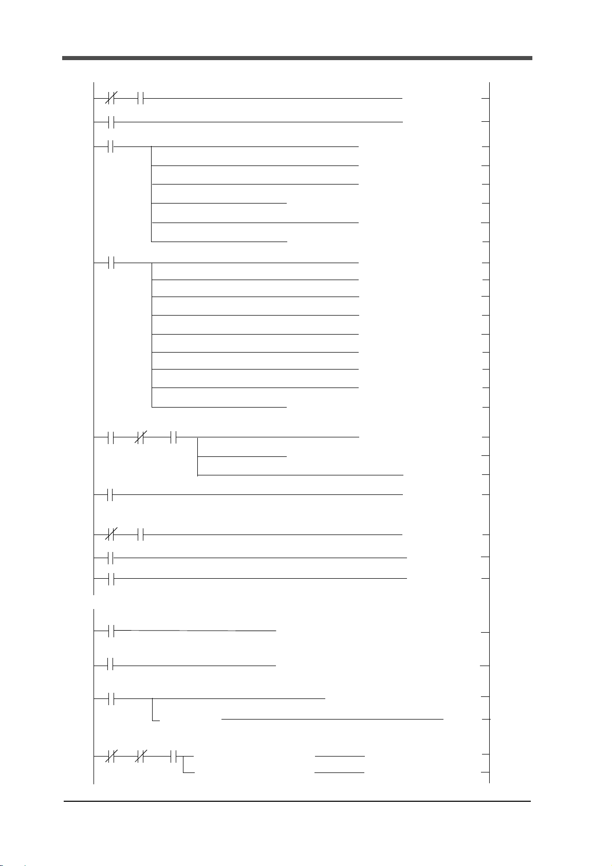
■Sample of ladder program
Rewriting Load HI/LO Limit (HI limit) to CODE No.0 by Request flag 2, the Load HI/LO Limit
(HI limit)
「In detail refer to CC-Link System Master/Local Module Type AJ61QBT11/A1SJ61QBT11 User’s
22
are increased from 0 to 9999 in succession.
Use CPU :A1SH
Station No. :1
Slot of Master :3 (The relay area to be used is X60 ~ X7F and Y60 ~ Y7F.)
Manual」
The following is a sample ladder program to change Load HI/LO Limit (HI limit) of work No.
2, section 1 using request flag 2.
After a value is written in Load HI/LO Limit (HI limit) , Load HI/LO Limit (HI limit) is read,
and the written value and read value are compared, and if they agree, the writing value is
incremented by 1, and it is repeated up to 9999, which is followed by 0.
Note) Set Load HI/LO Limit (LO limit) of work No. 2, section 1 to 0 or less in advance.
Page 26

7.Setting procedure
Initial setting
D300 = 9999
D300 = D300+1
After confirming Request flag 2 response OFF, writes the value of D300 into
After confirming Request flag 2 response ON, turns OFF Request flag 2.
After confirming Request flag 2 response OFF, requests reading out
After confirming Request flag 2 response ON, reads out the value (D302)
Compares D300 with D302
Sequence completion
"0" is substituted for D300
Yes
No
When Conform to
When Not conform to
FLOW
then turns Request flag2 OFF.
Load HI/LO Limit (HI limit).
Load HI/LO Limit (HI limit).
0~123 row Initial setting for Communication speed
96 row Remote device F381A/F388A occupies 4 stations of PLC start from station 1.
125 row RX PLC read value from F381A/F388A
135 row RWr PLC read value from F381A/F388A
145 row Copying Reguest flag 2 response to M200
202 row Writing Load HI/LO Limit (HI limit)
274 row Reading Load HI/LO Limit (HI limit)
308 row Copying read value to D302
337 row When each value coinsides with proceeds to 159 row.
350 row Data Initialization
23
Page 27
7.Setting procedure
X6FX60
M9038
1 cycle
D12
H1401
[MOV ]
96
X60
M1
M0
M9038
M0
M1
D0
D1
D2
K3
D3
K
1
D4
D5
D6
D7
D8
D10
D11
K8
K1
Y60
M2
[PLS
[SET
K1
K3
K1
D0
K0
D3
H0
H0
H0
H0
H0
H0
H0
H0
D4
D12
[RST
[SET
[PLS
[MOV
[MOV
H1
[MOV
[MOV
[MOV
[MOV
[MOV
[MOV
[MOV
[MOV
H10
H20
H6
H6
H6
H6
[TO
[TO
[TO
[TO
]
]
]
]
]
]
]
]
]
]
]
]
]
]
]
]
]
]
]
]
X6F
M1
X60 X6F
0
5
7
46
114
116
*<1device connected
>
[MOV
]
H6
[MOV
D9
*<Remote device F381A/F388A occupies 4
M1
1 cycle ON
M2
M3
M3
Y66
[SET
[SET
]
]
121
123
*
Up to here Initial setting for communication
(M200
D200H0E0H6
[FROM
]
D216H2E0H6
[FROM ]
M9036
M9036
[= D400 H4 ]
125
135
*<RX PLC read value from F381A/F388A >
ON at all times
ON at all times
*<
RWr PLC read value from F381A/F388A >
D200H4[WAND
]
M9036
ON at all times
)
Request flag 2 response
145
H8
D400
H10
]
H1 [+
]
[D= K9999 D300 ]
[D<>
K9999
D300
*<D300 =9999 , D300←0
>
159
D300
[DMOV
]
D300
M200 M9038 M100
Request
1 cycle
K0
stations of PLC start from station 1
>
flag 2
response
ON
ON
24
Page 28

D208
M100
M101
H0FFF7
[RST
[SET
]
]
H10D232H1E0H6
[TO ]
M200 M9038 M100
202
Request
1 cycle
ON
]
*<R /W
relay
OFF
>
D246D300 [MOV ]
[WAND
D247D301[MOV ]
D245K1306[MOV ]
*<(
Load HI/LO Limit (HI limit)
>
*<Reguest flag 2 ON
>
D208H4[WOR ]
H8D208
H160
[TO
]
*<To
M101
>
H6
*
M100
Sequence(Wiriting Load HI/LO Limit (HI limit)
)
M200 M9038 M101
255
*<When Reguest flag 2 response turns ON
Request
1 cycle
ON
*<To
M103
>
M103[SET ]
M101[RST
]
H8D208
H160
H6[TO
]
D208
H0FFFB
][WAND
*
M101 Sequence
*<
R/W relay Turns ON
>
D208H8
[WOR
]
274
M200 M9038 M103
Request
1 cycle
*<Load HI/LO Limit (HI limit)
>
D245K1306
[MOV
]
*<Reguest flag 2 ON
>
H8D208H160H6[TO ]
*<To
M104
>
]
]
M103[RST
M104[SET
D208H4
[WOR
]
*
M103 Sequence(Reading Load HI/LO Limit (HI limit)
)
D244H102[MOV ]
*<Work no. 2 Section 1
>
*<Work no. 2 Section 1
>
D244H102
[MOV
]
ON
flag 2
response
flag 2
response
flag 2
response
Reguest flag 2 goes OFF.
>
7.Setting procedure
25
Page 29

8.Outside dimensions
1 cycle
M105[RST ][ = D300 D302 ] [ = D301 D303 ]
337
*<To M100
>
M100[SET ]
M105
*
M105 Sequence(Comparing values
)
M9038
M100[SET ]
M101[RST ]
M102[RST ]
M103[RST ]
M104[RST ]
M105[RST ]
D300K0[DMOV ]
1 cycle ON
350
364
[END ]
*
Initialization
D303D231
[MOV
]
M104[RST
M105[SET
D302D230[MOV ]
M200 M9038 M104
Request
*<When Reguest flag 2 response turns ON
H8D208H160H6[TO ]
*<To M105
>
]
]
308
D208
H0FFFB
][WAND
*
M104 Sequence
ON
flag 2
response
Reguest flag 2 goes OFF.
>
ࠉ ࠉ
ࠉ
ࠉ
ࠉࠉ
8. Outside dimensions
26
 Loading...