


F372A
DIGITAL INDICATOR
OPERATION MANUAL
01JUN2016REV.3.11

INTRODUCTION
WARNING
CAUTION
INTRODUCTION
SAFETY PRECAUTIONS
INTRODUCTION
Thank you very much for purchasing our Digital Indicator F372A.
For good performance, and proper and safe use of the F372A, be sure to read this operation manual and
properly understand the contents of it before use. Also, carefully keep this operation manual so that it can
be referred to at any time.
BE SURE TO READ FOR SAFETY
Installation, maintenance and inspection of the F372A should be performed by personnel having technical
knowledge of electricity.
In order to have an F372A used safely, notes I would like you to surely follow divide into " "
and " ", and are indicated by the following documents. Notes indicated here are the serious
contents related to safely. Please use F372A after understanding the contents well.
WARNING
This sign forewarns the presence of hazards that could result in serious injury or
fatality when incorrectly handled.
CAUTION
This sign forewarns the presence of hazards that could result in personnel injury or
property damage when incorrectly handled.
1
1

WARNING
This sign forewarns the presence of hazards
that could result in serious injury or fatality
when incorrectly handled.
Warning on design
Warning on installation
Warning on wiring
WARNING
WARNING
● For the entire system to function safely when the F372A becomes faulty or malfunctions,
provide a safety circuit outside the F372A.
● Before using the F372A as described below, make sure to consult with our sales personnel.
- Use in environments not described in the operation manual.
- Use greatly impacting human lives and assets, such as medical devices, transport devices
entertainment devices, and safety devices.
● Do not modify the F372A. Doing so may cause fire or electric shocks.
● Do not install in the following environments.
- Places containing corrosive gas or flammable gas.
- Where the product may be splashed with water, oil or chemicals.
● Do not connect a commercial power source directly to the signal input/output terminals.
● Be sure to ground the protective ground terminal.
● The attached AC cable is designed for domestic use in Japan, and its rating is 125V AC, 7A.
For use at voltages exceeding the rating and for overseas use, have a separate AC cable
prepared.
● Before performing the following, make sure that no power is applied.
- Attachment/detachment of connectors of options, etc.
- Wiring/connection of cables to the terminal blocks.
- Connection of the earth cable.
● For connection to the signal input/output terminals, check the signal names and pin
assignment numbers, and then carry out wiring properly.
● Be sure to use crimp contacts for connection to the terminal blocks, and do not to connect
bare wires as they are.
● Be sure to install the attached terminal block cover after wiring to the power input terminals.
Otherwise, electric shocks may result.
● Before applying power, carefully check the wiring, etc.
2
2

WARNING
This sign forewarns the presence of hazards
that could result in serious injury or fatality
when incorrectly handled.
Warning during startup and maintenance
This sign forewarns the presence of hazards
that could result in personnel injury or property damage
when incorrectly handled.
Caution on installation
WARNING
WARNING
● Use at a proper power supply voltage.
● Do not damage the power cord. Doing so may cause fire or electric shocks.
● Do not touch any terminal while applying power. Doing so may cause electric shocks or
malfunctions.
● If the cover of the main body is opened, it may cause an electric shock internally. Even if the
power is off, the internal capacitor is charged. Contact us for internal inspection or repair.
● In the case of smoke, an abnormal smell or strange sound, immediately turn off the power,
and disconnect the power cable.
● As for the batteries used in F372A, do not at any time dismantle the batteries, change the
batteries shape by subjecting it to pressure or throw the batteries into fires as these may
cause the batteries to explode, catch fire or leak.
CAUTION
● Use the F372A as it is incorporated in a control panel, etc.
● Do not install in the following environments:
- Locations where temperature or humidity exceeds specifications;
- Locations subjected to drastic temperature fluctuations or icing and condensing;
- Outdoors or locations above 2,000m;
- Locations exposed to direct sunlight;
- Locations subject to dust accumulation;
- Locations with poor ventilation;
- Locations with a lot of salt and metal powder;
- Locations where the main unit is subject to direct vibration and shock.
● Take adequate shielding measures when using at the following locations.
- Near a power line.
- Where a strong electric field or magnetic field is formed.
- Where static electricity, relay noise or the like is generated.
● Install the F372A as far away from devices generating high frequency, high voltage, large
current, surge, etc., as possible. Also, carry out wiring separately from their power lines. Do
not carry out parallel wiring and common wiring.
● Do not use it, broken down.
3
3

CAUTION
This sign forewarns the presence of hazards
that could result in personnel injury or property damage
when incorrectly handled.
Caution on wiring
Caution during startup and maintenance
Caution during transportation
Caution during disposal
CAUTION
CAUTION
● Tighten the screws for the signal input/output terminals at the specified torque.
If they are loose, shorts, fire or malfunctions may occur.
Tightening torque: 0.5N• m
● For sensors, external inputs/outputs, RS-232C and options, use shielded cables.
● The temporary overvoltage applied to the power should not exceed 1500V.
● Set the correct Excitation Voltage for the sensor. (2.5V is set when F372A is dispatched
from us.)
● For turning on/off the power, be sure to keep intervals of 5 seconds or more.
● After power-on, make sure to warm up the F372A for at least 30 minutes or more before use.
● If the F372A is not used by the specified method, its protective performance may be
impaired.
● Maintenance
- When performing maintenance, disconnect the power.
- Do not wipe with a wet rag, or with benzine, thinner, alcohol, etc. Doing so may cause
discoloration or deformation of the F372A. In the case of heavy contamination, wipe off
the contamination with a cloth after dipping it into a diluted neutral detergent and wringing
it well, and then wipe with a soft, dry cloth.
● When the F372A is shipped, spacers made of corrugated cardboard are used as cushioning
materials.
Though it is factory-designed so that shocks can sufficiently be absorbed, breakage may
result if shocks are applied when the spacers are reused for transportation. If you send the
F372A to us for repair, etc., take adequate measures against shocks by using polyurethane
materials, etc., separately.
● If you dispose of the product, handle it as industrial waste.
● Remove the lithium batteries used in the F372A and make sure to dispose them according
to classification of waste collection.
4
4

RoHS-COMPLIANT PRODUCT
EN55011,EN61000-4-2,EN61000-4-3,EN61000-4-4
EN61000-4-5,EN61000-4-6,EN61000-4-8
EMC Directive EN61000-4-5 (Lightning Surge Immunity) is met by the F372A
body in combination with a lightning surge protector.
Point
RoHS-COMPLIANT PRODUCT
The parts and attachments (including the instruction manual, packaging box, etc.) used for this unit are
compliant with the RoHS Directive restricting the use of hazardous substances with regard to adverse
effects on the environment and human body.
What is RoHS?
It is an abbreviation for Restriction on Hazardous Substances, which is implemented by the European
Union (EU). The Directive restricts the use of six specific substances in electric and electronic equipment
handled within EU borders. The six substances are lead, mercury, cadmium, hexavalent chromium, PBB
(polybrominated biphenyls), and PBDE (polybrominated diphenyl ethers).
CONFORMITY WITH EC DIRECTIVES
The F372A Digital Indicator is a CE-marked EC-Directive-conforming product
(by the Council of the European Union).
RoHS-COMPLIANT PRODUCT
- EMC Directives EN61326-1
When installing, attention should be given to the following.
1. Since the F372A is defined as open type (built-in equipment), be sure to use it as installed and
fixed to a panel, etc.
2. Use shielded cables (for load cell(s), external input / output, and option).
3. When using the DeviceNet or CC-Link option, also pay attention to the precautions related to
conformity with EMC Directives provided by your PLC manufacturer.
5
5

CONFORMITY WITH EC DIRECTIVES
* PT-BE/FM and PT 2-PE/S-24AC-ST are registered
trademarks of PHOENIX CONTACT.
PT-BE/FM
PT 2-PE/S-24AC-ST
(DIN rail mount type)
< Shape >
6
4
2
5
3
1
L
N
IN OUT
L
N
PT 2-PE/S-24AC-ST
PT -BE/FM
Lightning surge protector
F372A
+
-
DC IN
×
+
-
< Connection >
To 2 4V DC
power supply
CAUTION
Be sure to ground of the lightning surge protector.
Without grounding, it will not function as a lightning surge
protector.
No lightning surge protector is included as standard (optionally available).
Purchase it from PHOENIX CONTACT or us.
We sell lightning surge protectors (PT 2-PE/S-24AC-ST) and lightning surge
protector terminal blocks (PT-BE/FM) as a set.
Specify "TSU03."
Point
CONFORMITY WITH EC DIRECTIVES
◆Connection of a lightning surge protector
EMC Directive EN61000-4-5 (Lightning Surge Immunity) is met by the F372A body in
combination with a lightning surge protector.
For conformity with EMC Directives, attach a lightning surge protector to the power supply line.
6
6

CONTENTS
This operation manual consists of a standard volume and expansion volume.
CONTENTS
<Standard>
CONTENTS
1 OUTLINE . . . . . . . . . . . . . . . . . . . . . . . . . . . . . . . . . . . . . . . . . . . . . . . . . . . 15
1-1. Contents of the Package . . . . . . . . . . . . . . . . . . . . . . . . . . . . . . . . . . . . . . . . . . . . . . 15
1-2. About Connectable Devices . . . . . . . . . . . . . . . . . . . . . . . . . . . . . . . . . . . . . . . . . . . . 15
1-3. Appearance Description . . . . . . . . . . . . . . . . . . . . . . . . . . . . . . . . . . . . . . . . . . . . . . . 16
■ Front panel . . . . . . . . . . . . . . . . . . . . . . . . . . . . . . . . . . . . . . . . . . . . . . . . . . . . 16
■ Rear panel. . . . . . . . . . . . . . . . . . . . . . . . . . . . . . . . . . . . . . . . . . . . . . . . . . . . . 17
2 INSTALLATION & CONNECTION . . . . . . . . . . . . . . . . . . . . . . . . . . . . . . . . 20
2-1. Installation . . . . . . . . . . . . . . . . . . . . . . . . . . . . . . . . . . . . . . . . . . . . . . . . . . . . . . . . . 20
2-2. Connection . . . . . . . . . . . . . . . . . . . . . . . . . . . . . . . . . . . . . . . . . . . . . . . . . . . . . . . . . 21
■ Power input connection . . . . . . . . . . . . . . . . . . . . . . . . . . . . . . . . . . . . . . . . . . . 21
■ Protective Ground Connection . . . . . . . . . . . . . . . . . . . . . . . . . . . . . . . . . . . . . 21
■ Analog input / output terminals connection . . . . . . . . . . . . . . . . . . . . . . . . . . . . 22
■ Load cell connection . . . . . . . . . . . . . . . . . . . . . . . . . . . . . . . . . . . . . . . . . . . . . 23
■ SI/F connection . . . . . . . . . . . . . . . . . . . . . . . . . . . . . . . . . . . . . . . . . . . . . . . . . 24
■ External I/O connection . . . . . . . . . . . . . . . . . . . . . . . . . . . . . . . . . . . . . . . . . . . 25
■ RS-232C interface connection . . . . . . . . . . . . . . . . . . . . . . . . . . . . . . . . . . . . . 26
■ Voltage output connection. . . . . . . . . . . . . . . . . . . . . . . . . . . . . . . . . . . . . . . . . 27
■ Connecting to cage clamp terminal block . . . . . . . . . . . . . . . . . . . . . . . . . . . . . 27
3 SETTING PROCEDURE . . . . . . . . . . . . . . . . . . . . . . . . . . . . . . . . . . . . . . . 28
3-1. Screens And Operations . . . . . . . . . . . . . . . . . . . . . . . . . . . . . . . . . . . . . . . . . . . . . . 28
■ Setting modes tree . . . . . . . . . . . . . . . . . . . . . . . . . . . . . . . . . . . . . . . . . . . . . . 28
■ F372A screen configuration . . . . . . . . . . . . . . . . . . . . . . . . . . . . . . . . . . . . . . . 30
■ About a setting call . . . . . . . . . . . . . . . . . . . . . . . . . . . . . . . . . . . . . . . . . . . . . . 31
4 CALIBRATION . . . . . . . . . . . . . . . . . . . . . . . . . . . . . . . . . . . . . . . . . . . . . . . 32
4-1. Calibration Procedures . . . . . . . . . . . . . . . . . . . . . . . . . . . . . . . . . . . . . . . . . . . . . . . . 33
4-2. Calibration Protect . . . . . . . . . . . . . . . . . . . . . . . . . . . . . . . . . . . . . . . . . . . . . . . . . . . 34
4-3. Calibration Value Selection (This step may be omitted if there is no change.) . . . . . 34
■ Calibration value selection by touch panel . . . . . . . . . . . . . . . . . . . . . . . . . . . . 34
■ Calibration value selection by external signal input . . . . . . . . . . . . . . . . . . . . . 35
4-4. Excitation Voltage. . . . . . . . . . . . . . . . . . . . . . . . . . . . . . . . . . . . . . . . . . . . . . . . . . . . 35
4-5. Unit . . . . . . . . . . . . . . . . . . . . . . . . . . . . . . . . . . . . . . . . . . . . . . . . . . . . . . . . . . . . . . . 35
7
7

CONTENTS
CONTENTS
4-6. Zero Calibration . . . . . . . . . . . . . . . . . . . . . . . . . . . . . . . . . . . . . . . . . . . . . . . . . . . . . 36
4-7. Equivalent Input Calibration . . . . . . . . . . . . . . . . . . . . . . . . . . . . . . . . . . . . . . . . . . . . 37
■ Registration method at decimal place . . . . . . . . . . . . . . . . . . . . . . . . . . . . . . . . 37
4-8. Actual Load Calibration . . . . . . . . . . . . . . . . . . . . . . . . . . . . . . . . . . . . . . . . . . . . . . . 38
4-9. Increment (This step may be omitted if there is no change.) . . . . . . . . . . . . . . . . . . . 38
4-10.Digital Offset (This step may be omitted if there is no change.) . . . . . . . . . . . . . . . . . 39
4-11.Digital Zero Limit(This step may be omitted if there is no change.) . . . . . . . . . . . . . . 39
5 SETTING OF FUNCTIONS . . . . . . . . . . . . . . . . . . . . . . . . . . . . . . . . . . . . . 40
5-1. Digital Zero . . . . . . . . . . . . . . . . . . . . . . . . . . . . . . . . . . . . . . . . . . . . . . . . . . . . . . . . .40
5-2. Digital Filter. . . . . . . . . . . . . . . . . . . . . . . . . . . . . . . . . . . . . . . . . . . . . . . . . . . . . . . . . 41
5-3. Analog Filter . . . . . . . . . . . . . . . . . . . . . . . . . . . . . . . . . . . . . . . . . . . . . . . . . . . . . . . .41
5-4. Motion Detect (MD) . . . . . . . . . . . . . . . . . . . . . . . . . . . . . . . . . . . . . . . . . . . . . . . . . . 41
5-5. Zero Tracking (ZT) . . . . . . . . . . . . . . . . . . . . . . . . . . . . . . . . . . . . . . . . . . . . . . . . . . . 42
5-6. Backlight . . . . . . . . . . . . . . . . . . . . . . . . . . . . . . . . . . . . . . . . . . . . . . . . . . . . . . . . . . . 42
5-7. Display Language Selection . . . . . . . . . . . . . . . . . . . . . . . . . . . . . . . . . . . . . . . . . . . . 43
5-8. SI/F Print Out . . . . . . . . . . . . . . . . . . . . . . . . . . . . . . . . . . . . . . . . . . . . . . . . . . . . . . .43
5-9. Indicate Color . . . . . . . . . . . . . . . . . . . . . . . . . . . . . . . . . . . . . . . . . . . . . . . . . . . . . . . 44
5-10.Comparison Functions . . . . . . . . . . . . . . . . . . . . . . . . . . . . . . . . . . . . . . . . . . . . . . . . 44
■ HI limit / LO limit / HH limit / LL limit . . . . . . . . . . . . . . . . . . . . . . . . . . . . . . . . . 45
■ Hysteresis . . . . . . . . . . . . . . . . . . . . . . . . . . . . . . . . . . . . . . . . . . . . . . . . . . . . . 45
■ Near zero. . . . . . . . . . . . . . . . . . . . . . . . . . . . . . . . . . . . . . . . . . . . . . . . . . . . . . 46
■ Comparison timing . . . . . . . . . . . . . . . . . . . . . . . . . . . . . . . . . . . . . . . . . . . . . . 46
■ Comparison output selection. . . . . . . . . . . . . . . . . . . . . . . . . . . . . . . . . . . . . . . 47
■ Alarm HI and LO limits . . . . . . . . . . . . . . . . . . . . . . . . . . . . . . . . . . . . . . . . . . . 48
5-11.Hold Functions . . . . . . . . . . . . . . . . . . . . . . . . . . . . . . . . . . . . . . . . . . . . . . . . . . . . . . 48
■ Hold setting --- Common --- . . . . . . . . . . . . . . . . . . . . . . . . . . . . . . . . . . . . . . 48
■ Hold setting --- Relative (Maximum / Minimum / Difference) --- . . . . . . . . . . . 50
■ Hold setting --- Inflection point --- . . . . . . . . . . . . . . . . . . . . . . . . . . . . . . . . . . 51
■ Hold setting --- Average value --- . . . . . . . . . . . . . . . . . . . . . . . . . . . . . . . . . . 53
■ Hold operation . . . . . . . . . . . . . . . . . . . . . . . . . . . . . . . . . . . . . . . . . . . . . . . . . . 53
■ How to specify the hold detection section(Peak, Valley, P-P, Average) . . . . . . 57
5-12.Multi-hold Function . . . . . . . . . . . . . . . . . . . . . . . . . . . . . . . . . . . . . . . . . . . . . . . . . . . 59
■ About changing of the setting work . . . . . . . . . . . . . . . . . . . . . . . . . . . . . . . . . . 60
■ Work copy . . . . . . . . . . . . . . . . . . . . . . . . . . . . . . . . . . . . . . . . . . . . . . . . . . . . . 60
5-13.Measurement Work Selection . . . . . . . . . . . . . . . . . . . . . . . . . . . . . . . . . . . . . . . . . . 61
5-14.Control Input Selection . . . . . . . . . . . . . . . . . . . . . . . . . . . . . . . . . . . . . . . . . . . . . . . . 61
5-15.B6 OFF Detection Wait. . . . . . . . . . . . . . . . . . . . . . . . . . . . . . . . . . . . . . . . . . . . . . . . 61
5-16.B8 OFF Detection Wait. . . . . . . . . . . . . . . . . . . . . . . . . . . . . . . . . . . . . . . . . . . . . . . . 62
5-17.Waveform Display . . . . . . . . . . . . . . . . . . . . . . . . . . . . . . . . . . . . . . . . . . . . . . . . . . . 62
■ Graphic display screen . . . . . . . . . . . . . . . . . . . . . . . . . . . . . . . . . . . . . . . . . . . 62
8
8

CONTENTS
CONTENTS
■ Cursor display screen . . . . . . . . . . . . . . . . . . . . . . . . . . . . . . . . . . . . . . . . . . . . 62
■ Graph plotting . . . . . . . . . . . . . . . . . . . . . . . . . . . . . . . . . . . . . . . . . . . . . . . . . . 63
■ Graph mode . . . . . . . . . . . . . . . . . . . . . . . . . . . . . . . . . . . . . . . . . . . . . . . . . . . 65
■ Interval time. . . . . . . . . . . . . . . . . . . . . . . . . . . . . . . . . . . . . . . . . . . . . . . . . . . . 65
■ Graph start level . . . . . . . . . . . . . . . . . . . . . . . . . . . . . . . . . . . . . . . . . . . . . . . . 65
■ Level detection conditions . . . . . . . . . . . . . . . . . . . . . . . . . . . . . . . . . . . . . . . . . 65
■ X(Time) end point . . . . . . . . . . . . . . . . . . . . . . . . . . . . . . . . . . . . . . . . . . . . . . . 66
■ Y(Load) start point and Y(Load) end point . . . . . . . . . . . . . . . . . . . . . . . . . . . . 66
5-18.Voltage Output . . . . . . . . . . . . . . . . . . . . . . . . . . . . . . . . . . . . . . . . . . . . . . . . . . . . . . 67
5-19.Screen Lock / Key Lock (B5 terminal function selection) . . . . . . . . . . . . . . . . . . . . . . 67
5-20.Event Output at the End of Graph Plotting . . . . . . . . . . . . . . . . . . . . . . . . . . . . . . . . . 68
5-21.RUN Output . . . . . . . . . . . . . . . . . . . . . . . . . . . . . . . . . . . . . . . . . . . . . . . . . . . . . . . . 68
5-22.RS-232C Interface . . . . . . . . . . . . . . . . . . . . . . . . . . . . . . . . . . . . . . . . . . . . . . . . . . . 69
■ Communication specifications. . . . . . . . . . . . . . . . . . . . . . . . . . . . . . . . . . . . . . 69
■ RS-232C interface setting . . . . . . . . . . . . . . . . . . . . . . . . . . . . . . . . . . . . . . . . . 70
■ Communication mode . . . . . . . . . . . . . . . . . . . . . . . . . . . . . . . . . . . . . . . . . . . . 70
■ Communication format . . . . . . . . . . . . . . . . . . . . . . . . . . . . . . . . . . . . . . . . . . . 71
6 OPTION . . . . . . . . . . . . . . . . . . . . . . . . . . . . . . . . . . . . . . . . . . . . . . . . . . . . 75
6-1. BCD Data Output (Option) . . . . . . . . . . . . . . . . . . . . . . . . . . . . . . . . . . . . . . . . . . . . . 75
■ Connector pin assignment . . . . . . . . . . . . . . . . . . . . . . . . . . . . . . . . . . . . . . . . 75
■ BCD output select . . . . . . . . . . . . . . . . . . . . . . . . . . . . . . . . . . . . . . . . . . . . . . . 76
■ BCD output rate . . . . . . . . . . . . . . . . . . . . . . . . . . . . . . . . . . . . . . . . . . . . . . . . 76
■ Logic switching . . . . . . . . . . . . . . . . . . . . . . . . . . . . . . . . . . . . . . . . . . . . . . . . . 76
■ BCD data hold. . . . . . . . . . . . . . . . . . . . . . . . . . . . . . . . . . . . . . . . . . . . . . . . . . 76
■ Equivalent circuit . . . . . . . . . . . . . . . . . . . . . . . . . . . . . . . . . . . . . . . . . . . . . . . . 77
■ Signal timing . . . . . . . . . . . . . . . . . . . . . . . . . . . . . . . . . . . . . . . . . . . . . . . . . . . 77
■ Self check . . . . . . . . . . . . . . . . . . . . . . . . . . . . . . . . . . . . . . . . . . . . . . . . . . . . . 78
6-2. D/A Converter (Option). . . . . . . . . . . . . . . . . . . . . . . . . . . . . . . . . . . . . . . . . . . . . . . . 78
■ Scale setting value selection . . . . . . . . . . . . . . . . . . . . . . . . . . . . . . . . . . . . . . . 79
■ Zero scale output value and full scale output value . . . . . . . . . . . . . . . . . . . . . 79
■ D/A output select . . . . . . . . . . . . . . . . . . . . . . . . . . . . . . . . . . . . . . . . . . . . . . . . 80
6-3. External I/O (Source type (ISC) option) . . . . . . . . . . . . . . . . . . . . . . . . . . . . . . . . . . . 81
7 SPECIFICATIONS . . . . . . . . . . . . . . . . . . . . . . . . . . . . . . . . . . . . . . . . . . . . 82
7-1. Specifications . . . . . . . . . . . . . . . . . . . . . . . . . . . . . . . . . . . . . . . . . . . . . . . . . . . . . . . 82
■ Analog section. . . . . . . . . . . . . . . . . . . . . . . . . . . . . . . . . . . . . . . . . . . . . . . . . . 82
■ Digital section . . . . . . . . . . . . . . . . . . . . . . . . . . . . . . . . . . . . . . . . . . . . . . . . . . 82
■ Standard interfaces . . . . . . . . . . . . . . . . . . . . . . . . . . . . . . . . . . . . . . . . . . . . . . 83
■ Options interfaces . . . . . . . . . . . . . . . . . . . . . . . . . . . . . . . . . . . . . . . . . . . . . . . 83
■ External input and output . . . . . . . . . . . . . . . . . . . . . . . . . . . . . . . . . . . . . . . . . 83
■ General . . . . . . . . . . . . . . . . . . . . . . . . . . . . . . . . . . . . . . . . . . . . . . . . . . . . . . . 83
■ Accessories. . . . . . . . . . . . . . . . . . . . . . . . . . . . . . . . . . . . . . . . . . . . . . . . . . . . 84
7-2. Dimensions. . . . . . . . . . . . . . . . . . . . . . . . . . . . . . . . . . . . . . . . . . . . . . . . . . . . . . . . . 84
■ Standard . . . . . . . . . . . . . . . . . . . . . . . . . . . . . . . . . . . . . . . . . . . . . . . . . . . . . . 84
■ Equipped with BCD parallel data output interface option . . . . . . . . . . . . . . . . . 85
■ Equipped with CC-Link interface option . . . . . . . . . . . . . . . . . . . . . . . . . . . . . . 85
9
9

CONTENTS
CONTENTS
■ Equipped with DeviceNet interface option. . . . . . . . . . . . . . . . . . . . . . . . . . . . . 86
7-3. F372A Block Diagram. . . . . . . . . . . . . . . . . . . . . . . . . . . . . . . . . . . . . . . . . . . . . . . . . 87
8 SUPPLEMENTS . . . . . . . . . . . . . . . . . . . . . . . . . . . . . . . . . . . . . . . . . . . . . 88
8-1. Error Display List . . . . . . . . . . . . . . . . . . . . . . . . . . . . . . . . . . . . . . . . . . . . . . . . . . . . 88
■ Sensor +error or Sensor -error . . . . . . . . . . . . . . . . . . . . . . . . . . . . . . . . . . . . . 88
■ +Over or -Over (Overflow error) . . . . . . . . . . . . . . . . . . . . . . . . . . . . . . . . . . . . 88
■ Overload (Overload error) . . . . . . . . . . . . . . . . . . . . . . . . . . . . . . . . . . . . . . . . . 88
■ Zero error (Zero calibration error) . . . . . . . . . . . . . . . . . . . . . . . . . . . . . . . . . . . 88
■ Span error (Span calibration error) . . . . . . . . . . . . . . . . . . . . . . . . . . . . . . . . . . 88
■ Zero limit (Digital zero limit error) . . . . . . . . . . . . . . . . . . . . . . . . . . . . . . . . . . . 88
8-2. Protect / Initialization . . . . . . . . . . . . . . . . . . . . . . . . . . . . . . . . . . . . . . . . . . . . . . . . . 89
■ Work setting protect . . . . . . . . . . . . . . . . . . . . . . . . . . . . . . . . . . . . . . . . . . . . . 89
■ System setting protect. . . . . . . . . . . . . . . . . . . . . . . . . . . . . . . . . . . . . . . . . . . . 89
■ Calibration protect . . . . . . . . . . . . . . . . . . . . . . . . . . . . . . . . . . . . . . . . . . . . . . . 89
■ Expansion protect . . . . . . . . . . . . . . . . . . . . . . . . . . . . . . . . . . . . . . . . . . . . . . . 89
■ Initialization . . . . . . . . . . . . . . . . . . . . . . . . . . . . . . . . . . . . . . . . . . . . . . . . . . . . 89
8-3. Self-Check . . . . . . . . . . . . . . . . . . . . . . . . . . . . . . . . . . . . . . . . . . . . . . . . . . . . . . . . .90
■ Self-check . . . . . . . . . . . . . . . . . . . . . . . . . . . . . . . . . . . . . . . . . . . . . . . . . . . . . 90
■ Password. . . . . . . . . . . . . . . . . . . . . . . . . . . . . . . . . . . . . . . . . . . . . . . . . . . . . . 91
8-4. Unit Setting List . . . . . . . . . . . . . . . . . . . . . . . . . . . . . . . . . . . . . . . . . . . . . . . . . . . . . 91
8-5. Setting Item List . . . . . . . . . . . . . . . . . . . . . . . . . . . . . . . . . . . . . . . . . . . . . . . . . . . . . 92
■ Work setting Comparison setting (WORK0 to WORK15). . . . . . . . . . . . . . . . 92
■ Work setting Hold setting (WORK0 to WORK15). . . . . . . . . . . . . . . . . . . . . . 92
■ Work setting Graph setting (WORK0 to WORK15) . . . . . . . . . . . . . . . . . . . . 93
■ Calibration (CAL0 to CAL3). . . . . . . . . . . . . . . . . . . . . . . . . . . . . . . . . . . . . . . . 94
■ System setting. . . . . . . . . . . . . . . . . . . . . . . . . . . . . . . . . . . . . . . . . . . . . . . . . . 94
■ Protect / Initialization . . . . . . . . . . . . . . . . . . . . . . . . . . . . . . . . . . . . . . . . . . . . . 95
■ Self check . . . . . . . . . . . . . . . . . . . . . . . . . . . . . . . . . . . . . . . . . . . . . . . . . . . . . 95
10
10

CONTENTS
CONTENTS
<Expansion>
CONTENTS
1 EXP. HOLD FUNCTIONS. . . . . . . . . . . . . . . . . . . . . . . . . . . . . . . . . . . . . . 101
1-1. Double Hold . . . . . . . . . . . . . . . . . . . . . . . . . . . . . . . . . . . . . . . . . . . . . . . . . . . . . . . 101
■ Screens appearing when double hold is selected . . . . . . . . . . . . . . . . . . . . . . 101
■ Double hold setting . . . . . . . . . . . . . . . . . . . . . . . . . . . . . . . . . . . . . . . . . . . . . 102
■ Hold operations . . . . . . . . . . . . . . . . . . . . . . . . . . . . . . . . . . . . . . . . . . . . . . . . 102
■ HI/LO limit comparisons of double hold . . . . . . . . . . . . . . . . . . . . . . . . . . . . . 113
1-2. Sample Hold Trigger Edge Selection . . . . . . . . . . . . . . . . . . . . . . . . . . . . . . . . . . . . 114
■ Sample trigger selection setting . . . . . . . . . . . . . . . . . . . . . . . . . . . . . . . . . . . 115
■ Sample trigger select . . . . . . . . . . . . . . . . . . . . . . . . . . . . . . . . . . . . . . . . . . . 115
1-3. Auto Reset Selection at the Start of Hold Detection. . . . . . . . . . . . . . . . . . . . . . . . . 116
■ Auto reset select setting . . . . . . . . . . . . . . . . . . . . . . . . . . . . . . . . . . . . . . . . . 116
■ Hold auto reset . . . . . . . . . . . . . . . . . . . . . . . . . . . . . . . . . . . . . . . . . . . . . . . . 117
1-4. Hold Off on Digital Zero . . . . . . . . . . . . . . . . . . . . . . . . . . . . . . . . . . . . . . . . . . . . . . 117
1-5. Renewal of Hold Value . . . . . . . . . . . . . . . . . . . . . . . . . . . . . . . . . . . . . . . . . . . . . . . 118
1-6. Hold End Timing . . . . . . . . . . . . . . . . . . . . . . . . . . . . . . . . . . . . . . . . . . . . . . . . . . . . 119
■ Hold operations . . . . . . . . . . . . . . . . . . . . . . . . . . . . . . . . . . . . . . . . . . . . . . . . 119
2 EXP. COMPARISON FUNCTIONS . . . . . . . . . . . . . . . . . . . . . . . . . . . . . . 120
2-1. Before Value Comparison . . . . . . . . . . . . . . . . . . . . . . . . . . . . . . . . . . . . . . . . . . . . 120
■ Before value comparison . . . . . . . . . . . . . . . . . . . . . . . . . . . . . . . . . . . . . . . . 120
■ Screens appearing when before value comparison is selected . . . . . . . . . . . 121
■ Before value renewal condition . . . . . . . . . . . . . . . . . . . . . . . . . . . . . . . . . . . . 121
■ Difference-HI/LO limit comparisons . . . . . . . . . . . . . . . . . . . . . . . . . . . . . . . . 121
■ Before value regulation . . . . . . . . . . . . . . . . . . . . . . . . . . . . . . . . . . . . . . . . . . 122
2-2. Before Value Comparison in Double Hold . . . . . . . . . . . . . . . . . . . . . . . . . . . . . . . . 122
■ Comparison standard . . . . . . . . . . . . . . . . . . . . . . . . . . . . . . . . . . . . . . . . . . . 122
■ Double hold and difference-HI/LO limit comparisons . . . . . . . . . . . . . . . . . . . 123
2-3. Relative Value Comparison (in expansion double hold only) . . . . . . . . . . . . . . . . . . 124
■ Screens appearing when relative value comparison is selected. . . . . . . . . . . 125
■ Relative-HI/LO limit comparison . . . . . . . . . . . . . . . . . . . . . . . . . . . . . . . . . . . 126
■ Comparison standard . . . . . . . . . . . . . . . . . . . . . . . . . . . . . . . . . . . . . . . . . . . 126
■ Relative value HI/LO limit comparison . . . . . . . . . . . . . . . . . . . . . . . . . . . . . . 126
2-4. Before Value Comparison and Relative Value Comparison
(in expansion Double Hold only) . . . . . . . . . . . . . . . . . . . . . . . . . . . . . . . . . . . . . . . 128
■ Screens appearing when before value comparison &
relative value comparison are selected. . . . . . . . . . . . . . . . . . . . . . . . . . . . . . 128
■ Difference Value- and relative-HI/LO limit comparisons . . . . . . . . . . . . . . . . . 128
11
3 EXP. GRAPH FUNCTION . . . . . . . . . . . . . . . . . . . . . . . . . . . . . . . . . . . . . 130
3-1. Graph Pre Trigger Display Function . . . . . . . . . . . . . . . . . . . . . . . . . . . . . . . . . . . . . 130
■ Pre trigger display setting . . . . . . . . . . . . . . . . . . . . . . . . . . . . . . . . . . . . . . . . 130
■ Pre trigger value . . . . . . . . . . . . . . . . . . . . . . . . . . . . . . . . . . . . . . . . . . . . . . . 130
11

CONTENTS
CONTENTS
4 EXP. OPERATION FUNCTIONS. . . . . . . . . . . . . . . . . . . . . . . . . . . . . . . . 131
4-1. CR Characteristic (Primary) Digital Filter . . . . . . . . . . . . . . . . . . . . . . . . . . . . . . . . . 131
■ Digital filter character. . . . . . . . . . . . . . . . . . . . . . . . . . . . . . . . . . . . . . . . . . . . 131
4-2. Averaging on Digital Zero . . . . . . . . . . . . . . . . . . . . . . . . . . . . . . . . . . . . . . . . . . . . . 131
■ Average time on digital zero . . . . . . . . . . . . . . . . . . . . . . . . . . . . . . . . . . . . . . 132
4-3. RUN Output Selection . . . . . . . . . . . . . . . . . . . . . . . . . . . . . . . . . . . . . . . . . . . . . . . 132
■ RUN output selection . . . . . . . . . . . . . . . . . . . . . . . . . . . . . . . . . . . . . . . . . . . 132
5 EXP. OPTION FUNCTION . . . . . . . . . . . . . . . . . . . . . . . . . . . . . . . . . . . . 133
5-1. BCD Output Data Selection . . . . . . . . . . . . . . . . . . . . . . . . . . . . . . . . . . . . . . . . . . . 133
6 STANDARD INTERFACES . . . . . . . . . . . . . . . . . . . . . . . . . . . . . . . . . . . . 134
6-1. SI/F . . . . . . . . . . . . . . . . . . . . . . . . . . . . . . . . . . . . . . . . . . . . . . . . . . . . . . . . . . . . . . 134
6-2. RS-232C. . . . . . . . . . . . . . . . . . . . . . . . . . . . . . . . . . . . . . . . . . . . . . . . . . . . . . . . . . 134
7 OPTION INTERFACES . . . . . . . . . . . . . . . . . . . . . . . . . . . . . . . . . . . . . . . 141
7-1. BCO Option . . . . . . . . . . . . . . . . . . . . . . . . . . . . . . . . . . . . . . . . . . . . . . . . . . . . . . . 141
■ BCD output data list . . . . . . . . . . . . . . . . . . . . . . . . . . . . . . . . . . . . . . . . . . . . 141
7-2. DAV/DAI Option . . . . . . . . . . . . . . . . . . . . . . . . . . . . . . . . . . . . . . . . . . . . . . . . . . . . 142
7-3. CC-Link Option . . . . . . . . . . . . . . . . . . . . . . . . . . . . . . . . . . . . . . . . . . . . . . . . . . . . . 142
7-4. DeviceNet Option . . . . . . . . . . . . . . . . . . . . . . . . . . . . . . . . . . . . . . . . . . . . . . . . . . . 142
8 SUPPLEMENTS . . . . . . . . . . . . . . . . . . . . . . . . . . . . . . . . . . . . . . . . . . . . 143
8-1. Setting Item List . . . . . . . . . . . . . . . . . . . . . . . . . . . . . . . . . . . . . . . . . . . . . . . . . . . . 143
■ Work setting Comparison setting (WORK0 to WORK15). . . . . . . . . . . . . . . 143
■ Work setting Hold setting (WORK0 to WORK15). . . . . . . . . . . . . . . . . . . . . 145
■ Work setting Graph setting (WORK0 to WORK15) . . . . . . . . . . . . . . . . . . . 149
■ RS-232C special setting (Work setting) . . . . . . . . . . . . . . . . . . . . . . . . . . . . . 149
■ RS-232C special setting (Calibration setting) . . . . . . . . . . . . . . . . . . . . . . . . . 149
■ Calibration (CAL0 to CAL3). . . . . . . . . . . . . . . . . . . . . . . . . . . . . . . . . . . . . . . 150
■ System setting. . . . . . . . . . . . . . . . . . . . . . . . . . . . . . . . . . . . . . . . . . . . . . . . . 151
■ Expansion setting . . . . . . . . . . . . . . . . . . . . . . . . . . . . . . . . . . . . . . . . . . . . . . 153
12
12

STANDARD
13
13

M E M O
14
14

1-1. Contents of the Package
1 OUTLINE
05JAN2005REV.1.00
DYNAMICFORCEPRO CESSOR
F372A
INDICATOR
[
]
F372A body ・・・1 F372A operation manual ・・・1
External input / output connector ・・・1set
Connector: FCN-361J024-AU
Cover : FCN-360C024-B
Strain gauge type sensor
Printer Display Various converters
(Option)(Option)
(Option)
(Option)
PC
PLC
D/A Converter
Valve, recorder
1 OUTLINE
Chapter
1
The packaging box contains the following.
Be sure to check them before use.
OUTLINE
1-2. About Connectable Devices
15
15

1 OUTLINE
Comparison
Indicated value
Setting input
Hold status display
Setting mode
Digital zero
Touch panel
Status indicator
Display change
button
display
button
status display
display
screen call
button
button
lamp
Comparison display Hold display Graph display
Lamp indication Status
Green lighting Steady state
Red lighting
Writing into internal NOVRAM. Do not turn off the power of
the F372A.
Yellow blink
The voltage of the lithium battery for internal memory backup
has dropped. The battery needs to be replaced. Ask us for
replacement of the battery.
Chapter
1
OUTLINE
1-3. Appearance Description
■Front panel
Touch panel display
This is the touch panel display for displaying an indicated value and graph set value and for setting
various setting items of the F372A. During measurement, a comparison display, hold display and
graph display can be selected according to the function in use.
Status indicator lamp
16
16

■Rear panel
Signal input / output
Protective ground
Option board
DC power input
RS-232C connector
Analog input / output
connector
connector
terminal block
mounting slot
Frame ground
7
- MONITOR
6
+ MONITOR
5SHIELD
4
+ SIG
3
- EXC
2
- SIG
1
+ EXC
A1
*
COM1 B1
*
COM2
A2 out HH B2 in WORK0
A3 out HI B3 in WORK1
A4 out OK B4 in WORK2
A5 out LO B5 in WORK3(LOCK)
A6 out LL B6 in T/H
A7
*
COM1 B7 in COM2
A8 out HOLD END(H/E) B8 in SECTION
A9 out RUN B9 in D/Z
A10 out EVENT B10 in GRAPH TRIG
A11 out SI/F B11 in CAL0
A12 out SI/F B12 in CAL1
Analog input / output connector
1 OUTLINE
Chapter
1
OUTLINE
Adaptable plug (ETB42-07P) (manufactured by OSADA or equivalent)
(Connector optional type: CN80)
Signal input / output connector
17
Adaptable plug (FCN-361J024-AU) (manufactured by FUJITSU COMPONENT or equivalent)
Connector cover (FCN-360C024-B (manufactured by FUJITSU COMPONENT or equivalent)
(Connector & Cover optional type: CN50)
17

1 OUTLINE
→ page44 "Comparison
Functions"
→ page68 "RUN Output"
The input for controlling the hold signal.
→ page48 "Hold Functions"
Chapter
1
OUTLINE
+ EXC
- EXC
+ SIG
- SIG
SHIELD
See the section on "Load cell connection" page 23 for connection.
+ MONITOR
- MONITOR
See the section on "Voltage output connection" page 27 for connection.
COM1 The terminal common to output signals.
OK
HI
LO
HH
LL
RUN
The terminal for connecting to a strain-gage sensor.
The voltage output terminal for sensor input monitor.
→ page67 "Voltage Output"
Outputs the OK signal.
Outputs the HI signal.
Outputs the LO signal.
Outputs the HH signal.
Outputs the LL signal.
Outputs the RUN signal.
HOLD END
(H/E)
EVENT Outputs the event signal when graph plotting ends.
See the section on "External I/O connection" page 25 for connection.
COM2 The terminal common to input signals.
WORK0
WORK1
WORK2
WORK3(LOCK)
T/H
SECTION
D/Z The input for digital zero (making the indicated value zero).
GRAPH
TRIG
CAL0
CAL1
Outputs the hold end signal.
→ page48 "Hold Functions"
Selects the work No. for the multi-hold function.
→ page59 "Multi-hold Function"
WORK3 is also usable as a LOCK terminal.
→
page67 "Screen Lock / Key Lock (B5 terminal function selection)"
→ page40 "Digital Zero"
The input for controlling the drawing of graphic display.
→ page63 "Graph plotting"
Selects the CAL No. for calibration value selection function.
→ page35 "Calibration value selection by external signal input"
See the section on "External I/O connection" page 25 for connection.
SI/F The 2-wire serial interface for coupling a UNIPULSE printer,
See the section on "SI/F connection" page 24 for connection.
18
18
external display, etc.

DC power input terminal block
Connect the DC power cord. The power supply voltage is 24V DC (±15%).
Adaptable crimp terminal [TMEV1.25-3S]
Frame ground
Please ground the frame ground terminal to prevent failures due to static electricity.
(The frame and the frame ground terminal are conducted.)
It may be better to remove depending on the environment of the installation location.
Protective ground
Be sure to ground the protective ground terminal to prevent electric shocks.
Optional slot
Any one of the following optional boards can be mounted.
- BCD data output
- D/A converter (voltage or current output)
- CC-Link interface (CC-Link is an abbreviation for "Control & Communication Link".)
- DeviceNet interface
1 OUTLINE
Chapter
1
OUTLINE
RS-232C connector
RS-232C connector to transmit / receive measurement data and status information, etc.
The adaptable plug is HOSIDEN-manufactured TCP8080-015267 or equivalent.
Optionally available RS-232C cable (cross) [CA81-232X] is connectable.
19
19

2 INSTALLATION & CONNECTION
2 INSTALLATION & CONNECTION
92mm
Panel-cut
+1
0
–
Panel thickness
1.6 to 3.2mm
dimensions
92mm
+1
0
–
Chapter
2
INSTALLATION & CONNECTION
2-1. Installation
To install the F372A into a control panel, use the following procedure.
1. Make a hole in the panel according
to the panel-cut dimensions.
2. Remove the screws (two), and
remove the guide rails from both
sides.
* Do not use other screws than
those installed to the F372A body.
3. Fit in the F372A from the front of
the panel.
4. Install from the rear the guide rails
having been removed from both
sides in Step 2, and fix them with
the screws (two).
20
20

2-2. Connection
Black screw
Red screw
Within 6mm
CAUTION
Be aware that the voltage drops depending on the wire thickness and length.
Also, never input an AC power source. Doing so will cause a failure.
Protective
M4
ground
■Power input connection
Connect the positive (+) side of the power source to
the red screw side of the terminal block on the back
of the F372A, and its negative (-) side to the black
screw side. The input voltage is 24V DC(±15%).
■Protective Ground Connection
2 INSTALLATION & CONNECTION
Chapter
2
The grounding terminal is for prevention of electric shocks.
Use an approx. 0.75mm
2
thick wire, and be sure to ground.
1. Make sure that no power is applied.
2. Remove the screws(M4) at the protective
ground.
3. Align the solderless terminals(M4) with the
screw holes, and then tighten the screws.
WARNING
- Connect with no power applied because it may cause an electric shock.
- Since the F372A has no power switch, install a breaker.
INSTALLATION & CONNECTION
- Be sure to ground the protective ground terminal to prevent electric shocks.
Do not use other screws than that attached to the main body.
21
21

Chapter
5mm
Adaptable plug ETB42-07P (attachment)
Tighten.
(Turn clockwise.)
Pin No. 1
We sell it as CN80 (optional).
Pin No. 7
(Turn counterclockwise.)
Loosen.
Pin No. 7
Pin No. 1
Tighten.
(Turn clockwise.)
Tighten.
(Turn clockwise.)
Loosen.
(Turn
counterclockwise.
.)
Loosen.
(Turn
counterclockwise.
.)
When installing the terminal block to the F372A body,
check its orientation. (See the illustration at the right.)
Attention
Insert side
Right side
2 INSTALLATION & CONNECTION
■Analog input / output terminals connection
How to connect
1. Strip 5mm of the covering of the wire to be
connected.The size of connectable wires is
from 0.21 to 3.31mm
2
(AWG12 to 24).
2
2. Twist the tip to such an extent that it will not
spread out.
INSTALLATION & CONNECTION
3. Loosen the screw with a screwdriver to open
the connection hole.
A Phillips screwdriver 3 to 3.5mm #1 in shaft
diameter is recommended.
(Precision screwdriver, etc.)
4. Insert the wire into the connection hole so as
not to let the tip spread out.
5. Tighten the screw with the screwdriver.
0.5Nm of tightening torque is recommended.
6. Lightly pull the wire to make sure that it is securely clamped.
7. Insert the wire-connected plug into the
F372A body, and tighten the screws (two).
How to remove the terminal block
1. Loosen the screws (two) with a screwdriver.
2. Remove the terminal block by giving it
a strong pull.
22
22

■Load cell connection
( + EXC)
( - EXC)
( + SIG)
( - SIG)
(SHIELD)
+
IN
-
OUT
-
IN
+
OUT
1
2
3
4
F372A
5
( + EXC)
( - EXC)
( + SIG)
( - SIG)
+
IN
-
OUT
-
IN
+
OUT
F372A
1
2
3
4
(SHIELD)
5
- 4-wire sensor
- 6-wire sensor
2 INSTALLATION & CONNECTION
Chapter
2
Short-circuit +EXC with +S and -EXC with -S for connecting a 6-wire strain-gage sensor.
Cable colors of sensors
Cable colors of sensors may differ from one manufacturer to another (it may even differ from one
model to another for some products). Refer to the sensor manual (or data sheet) and check signal
names and colors in order to connect the cables correctly.
INSTALLATION & CONNECTION
23
23

Chapter
Converter
Display
Printer
SI/F
A12
A11
←
Inside Outside
→
F372A
2
INSTALLATION & CONNECTION
2 INSTALLATION & CONNECTION
■SI/F connection
The 2-wire serial interface has connective ability for coupling a UNIPULSE printer, external
display, etc.
Connect from A11 and A12 of the external input/output connector.
The interface is nonpolarized and up to three external instruments may be connected.
A two-core parallel cable or a cabtyre cable (Wire with covering thickened for construction) may be
used for connection.
When a two-core parallel cable or a cabtyre cable is used, the transmitting distance is
approximately 30m. When a two-core shielded twisted pair cable is used, the transmitting distance
is approximately 300m.
Do not parallel it with AC lines and high-voltage lines. It may cause of malfunction.
24
24

2 INSTALLATION & CONNECTION
The Source type (ISC) for external output signal can be selected at the time of the
purchase, as an option. The method to connect external input/output signal is also
different when source type is installed. Refer to "6-3.External I/O (Source type (ISC)
option)" on page 81. for details of source type (ISC).
CAUTION
COM1
Spark Killer
F372A Inside
DC
Relay
Vext
Supply an external power source for a relay drive
Output Data Tr
OFF OFF
ON ON
● Output Transistor Status
A1
A7
A2~6
A8~10
Vext
PLC etc.
Power
Supply
Plus common connection
Load
power source (Vext).
COM2
Relay
+12V
F372A Inside
IN
IN
Open → OFF
Short → ON
B2~6
B8~12
B7
B1
Push
Switch
Toggle
Switch
TTL Open Collector
(ON when IN is HI)
- The external element is required to withstand Ic=10mA.
- Leakage from the external element is required to be
100μA or below.
■External I/O connection
How to connect external output (Sink type)
The external output circuit is operated through an open collector. A1(A7) COM1 is the common
terminal. The open collector output capacity is 30mA and the withstand voltage is up to 30V.
- Equivalent circuit
Chapter
2
25
How to connect external input
(minus common connection of no-voltage contact input type)
A signal is inputted to the signal input circuit by short-circuiting or opening the input terminal and
the COM2 terminal. Short-circuiting is effected by means of a contact (such as a relay or a switch)
or a noncontact (such as a transistor or an open-collector TTL).
INSTALLATION & CONNECTION
25

Chapter
Connector
Pan-head machine screw
M2×8 (short) (two)
Nut M2 (four)
Pan-head machine screw
M2×10 (long) (two)
Washer (two)
Case (two)
Screw (two)
Pin No. Signal name
1DCD
2RXD
3TXD
4DTR
5GND
6DSR
7RTS
8CTS
Case F.G
Example of cabling
The following shows an example of connection between DTE-DTE terminals.
This will require modification depending on the equipment to be connected.
For details, see the operation manual of the equipment to be connected.
Adaptable plug TCP8080-015267
(manufactured by HOSIDEN or equivalent)
(Connector optional type: CN60)
Insert
6
7
8
5
4
2
1
3
Wire connection surface
Side view
Metal case
Plastic cover
Secure with
Fit the metal cases into the Din connector,
and cap with the plastic covers.
hardware
DCD
DSR
RXD
TXD
DTR
GND
RTS
CTS
1
6
2
3
4
5
7
8
4
3
2
1
6
5
8
7
9
DTR
TXD
RXD
DCD
DSR
GND
CTS
RTS
RI
TCP8080-015267 or equivalent D-Sub 9pin
F372A PC etc.
Cabling diagram CA81-232X(optional)
* This connection diagram shows cabling
applicable to the case where your PC is DTE
(data terminal equipment).
For connection with DCE (data circuitterminating equipment), such as a modem,
use straight type cabling.
* Prepare cabling after reconfirmation of the
connector shape and signal lines (pin
assignments) of the equipment you use.
2
INSTALLATION & CONNECTION
2 INSTALLATION & CONNECTION
How to assemble the connector
1. Set the connector and screws (two) into the grooves of the case (one side).
2. Cover with the other case, and fit the cases.
3. Tighten the M2×8 pan-head machine screws (two). Tighten the M2×10 pan-head
machine screws (two). Be aware that washers should be set to the M2×10 panhead machine screws (two).
■RS-232C interface connection
This connector connects the RS-232C.
26
26

2 INSTALLATION & CONNECTION
+
-
6
7
+
MONITOR
← F372A Inside Outside →
F.G, shield, etc.
-
MONITOR
External
equipment
5 to 6mm
CAUTION
- Cable can be from 24 to 14AWG (0.2 to 2.5mm2)
- It is not necessary to solder the cable wires or to fix a solderless terminal.
- If several cables to be inserted to the same hole, twist those cable wires
together and insert.
- If you connect a cable (load cell(s), SI/F, external input and output),
please turn off and be sure to perform the power supply of a main part.
■Voltage output connection
The monitor output terminal is an interface to extract analog voltage proportional to sensor signal
inputs.
- Since the ±MONITOR terminals are not insulated from the internal circuit, use two-core shielded
twisted pair wires for connection with external equipment, and carry out with as short a wiring as
possible.
- Do not short-circuit. Doing so will cause a failure.
- Do not apply voltage from the outside. Doing so will cause breakage.
Chapter
2
■Connecting to cage clamp terminal block
The output terminal D/A option is using the cage clamp system terminal stand. Please connect in
the following procedure.
1. Strip the casing 5 - 6mm on the cable to be
connected.
2. Twist the bare wire to fit the terminal hole.
3. Insert the supplied screwdriver into the
upper hole and lift upward.
4. Insert the twisted wires into the lower hole.
5. Make sure cable is clamped securely and
does not come out with a slight tug.
INSTALLATION & CONNECTION
27
27

3 SETTING PROCEDURE
3 SETTING PROCEDURE
Ordinary display screen
Setting menu screen
PAGE1
HH Limit (P45)
HI Limit (P45)
LO Limit (P45)
LL Limit (P45)
Hysteresis (P45)
PAGE2
Alarm HI Limit (P48)
Alarm LO Limit (P48)
Near Zero (P46)
Comp. Timing (P46)
Comp.Output Sel.
(P47)
PAGE1
Graph Mode (P65)
Y(LD) Start Point(P66)
Y(LD) End Point (P66)
X(TM) End Point (P66)
Graph Start Level
(P65)
PAGE2
Interval Time (P65)
Level detection conditions
(P65
)
PAGE1
Hold Mode (P48)
Hold Start Level (P49)
Section Time (P49)
Level detection Condition
(P50)
Operation
Hold Setting
Graph Setting
PAGE2
Motion Detect (P41)
Zero Tracking (P42)
Vol. Out Filter (P67)
Indicate Color (P44)
B5 Func. Select (P67)
PAGE1
Digital Filter (P41)
Analog Filter (P41)
Backlight (P42)
Language (P43)
SI/F Print Out (P43)
PAGE3
B6 OFF Det. Wait
(P61)
B8 OFF Det. Wait
(P62)
Meas. Work Select
(P61)
Contr. Input Sel. (P61)
Password (P91)
PAGE2
Delimiter (P70)
Flow Control (P70)
PAGE1
Com. Mode (P70)
Baudrate (P70)
Data Bit (P70)
Stop Bit (P70)
Parity Bit (P70)
PAGE2
<Sample hold>
Samp.Removal Val.
(P50)
<Inflection point hold>
Inf. Minimum Slope
(P51)
Inf. F Slope Time (P51)
Inf. R Slope Time (P51)
Inf. Removal Val. (P50)
Det. Start Cond. (P49)
<Relative (Maximum /
Minimum / Difference) hold>
Rel. Minimum Count
(P51)
Rel. magnification (P51)
Det. Start Cond. (P49)
<Peak hold or Valley hold,
and Section setting; Level>
Hold Stop Level (P49)
<Average hold>
Ave. Sample Num.(P53)
Work Setting
Comp. Setting
RS-232C Setting
System Setting
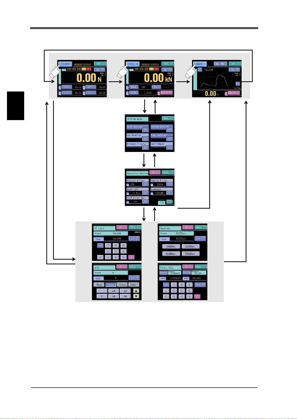
3-1. Screens And Operations
■Setting modes tree
Chapter
3
SETTING PROCEDURE
28
28

3 SETTING PROCEDURE
Exp. Setting Protect / Init
PAGE1
Work Protect (P89)
System Protect (P89)
Cal. Protect (P34)
Exp. Protect (P89)
Initialization (P89)
Self Check
PAGE1
LCD Check (P90)
KEY Check (P90)
MEM Check (P90)
I/O Check (P90)
DSP Check (P90)
COM Check (P91
)
Calibration
PAGE2
Unit (P35)
Increment (P38)
Digital Offset (P38)
DZ Limit (P39)
PAGE1
Exc. Voltage (P35)
Zero Cal. (P36)
Equiv. Cal. (P37)
Actual Cal (P38)
Cal. Select (P33)
Option Setting
Setting functions vary
with options.
See the Expansion of
this manual.
(P99)
PAGE1
Output Select
(P76)
Output Rate (P76)
Self Check (P78)
See the DeviceNet
operation manual.
See the CC-Link
operation manual.
BCD OUTPUT
CC-Link DeviceNet
PAGE1
Output Select (P80)
Zero Scale (P79)
Full Scale (P79)
Scale Set. Select (P79)
D/A OUTPUT
Chapter
3
SETTING PROCEDURE
29
29
3 SETTING PROCEDURE
Measurement
Setting
Back
Mode buttons
Setting buttons
HOME
Measurement
Back
[Ordinary display screen]
[Setting menu screen]
[Set value selection screen]
[Set value entry screen]
Back
Set value entry from the
ordinary display screen
■F372A screen configuration
Chapter
3
SETTING PROCEDURE
30
30

■About a setting call
SET. System setting Page 1
↑↑
Setting menu Item classification
→→
Operation
→
↑
Page
Setting call
Setting menu Item classification
Page 1 Page 2 Page 3
In this manual, a setting function call is described as follows.
Example) Digital filter
3 SETTING PROCEDURE
Chapter
This call can be made by the following procedure.
1. Press the [SET.] button on the ordinary display screen.
2. The setting menu screen appears. Select the item.
3
SETTING PROCEDURE
3. The setting function setting screen appears. Select the function.
31
31

Chapter
4 CALIBRATION
F372A
Strain gauge sensor
Rated output value (mV/V)+Indicated value
A data sheet is attached to a strain-gage sensor at the time of purchase.
Enter the rated capacity value and the rated output value described on
the data sheet into the F372A.
Point
Strain gauge sensor
Indicated value
F372A
Actual
load
4 CALIBRATION
About calibration
Calibration is performed for matching the F372A to a strain-gage sensor. The following two types
of calibration are available for the F372A.
● Equivalent input calibration
Calibration is performed without an actual load by entering the rated output value (mV/V) and
the capacity (to be indicated) of the strain-gage sensor by the keys. Calibration is easily
performed when no actual load is available.
For example, the gain is automatically determined by entering:
4
CALIBRATION
2.001mV/V (rated output) - 100.0kg (capacity)
● Actual load calibration
Apply an actual load to the strain-gage sensor and enter the actual load value by the keys for
calibration. Calibration is accurately performed with reductions in errors.
32
32

4-1. Calibration Procedures
4-8.
Actual Load
Calibration
or
*
Equivalent
4-7.
*
Increment
4-9.
Calibration Protect
Calibration Protect
Digital Offset
4-2.
4-10.
4-2.
Calibration Selecttion
4-3.
Excitation Voltage
4-4.
Digital Zero Limit
4-11.
Unit
4-5.
*
*
…It is indispensable.
Zero Calibration
4-6.
Calibration
Follow the steps below to perform equivalent input calibration and actual load calibration.
Release the calibration protection.
Set the calibration value No.
(Set "0" for use with only one selection.)(This step
may be omitted if there is no change.)
4 CALIBRATION
Set the excitation voltage according to the sensor
used.
Set the unit of the values displayed.
Set the zero point of the strain-gage sensor in no-
load condition (with the sensor unloaded).
Equivalent Input Calibration
Enter the rated output value and reading of the
strain-gage sensor.
At this time, also input the decimal point.
Actual Load Calibration
Enter the span (gain) point of the strain-gage
sensor with a load applied to the sensor.
At this time, also input the decimal point.
Enter the minimum value of digital increments.
(This step may be omitted if there is no change.)
Chapter
4
CALIBRATION
33
The calibrated value can be offset in advance.
(When not using, set "0".)
(This step may be omitted if there is no change.)
Set the load limit to allow digital zero.(This step
may be omitted if there is no change.)
Turn on the calibration protection for preventing
misoperation.
33

4 CALIBRATION
SET. Protect / Init. Page 1
→→
Calibration Mode Setting
Excitation Voltage
Zero Calibration
Actual Load Calibration
Equivalent Input Calibration
Increment
Unit
Digital Offset
DZ Limit
4-2. Calibration Protect
Chapter
4
CALIBRATION
Calibration-related set values can be protected so that they will not be changed by misoperation.
When Cal. Protect is ON, no change can be made while the alarm sounds.
ON :Protected
OFF :Unprotected
How to set
1. Press the [SET.] button.(refer to page 36)
2. Press the [Protect / Init.] button.
3. Press the [Cal. Protect] button.
4. Select the ON/OFF and determine with
the [OK] button.
4-3. Calibration Value Selection
(This step may be omitted if there is no change.)
By storing up to four calibration values in the memory, the desired calibration value can be called to
switch the indicated value. Setting values that can be switched are as follows:
34
■Calibration value selection by touch panel
Select "0" - "3" by pressing the button on the CALIBRATION screen.
When not using, set "0".
34

4 CALIBRATION
B1 or B7 COM2
B11 CA L0
B12 CA L1
CAUTION
It takes one second at maximum for
the changed calibration value to
become effective. During this time,
the calibration value is indefinable.
Also, the indicated value is
accordingly indefinable.
I/O connector
SET. Calibration Page 1
→→
SET. Calibration Page 2
→→
■Calibration value selection by external signal input
With this function, four types of calibration values can be selected with external selector signals
CAL0 and CAL1 (when the calibration value selection setting is external). Set EXT 0 by pressing
the button on the CALIBRATION screen. According to the input conditions of external
signal inputs CAL0 and CAL1, the display changes as EXT 0 to EXT 3. Normally, when there is no
input to CAL0 and CAL1 (the terminals are open), calibration value 0 is selected. When each
terminal is in the following condition, each calibration value is selected.
CAL1 CAL0 Calibration value
Open Open Calibration value 0
Open Short-circuit Calibration value 1
Short-circuit Open Calibration value 2
Short-circuit Short-circuit Calibration value 3
Chapter
4
4-4. Excitation Voltage
Select the bridge voltage supplied to the strain gauge sensor.
The bridge voltage can be selected from 2.5V and 10V.
After this setting, be sure to perform calibration.
How to set
4-5. Unit
Set the unit of the values displayed. For settable units, see the "Unit Setting List"on page 91.
How to set
1. Press the [SET.] button. (refer to page 36)
2. Press the [Calibration] button. (refer to page 36)
CALIBRATION
3. Select page 2, and
press the [Unit]
button.
35
35

4 CALIBRATION
* Even if the unit is changed, the display
value (calibration value) will not change.
SET. Calibration Page 1
→→
4. First select the category, and then
select the unit and determine with
the [OK] button.
Select by scrolling with the
button.
4-6. Zero Calibration
Chapter
4
CALIBRATION
Set the zero point in no-load condition.
How to set
1. Press the [SET.] button.
2. Press the [Calibration] button.
3. Press the [Zero Cal.] button.
4. Press [OK] button after confirming no-
load was applied to the sensor.
36
36

4 CALIBRATION
→→
The display of the decimal point
→ →Press
of the input value moves.
・The decimal point ten keys are registered pushing at the end after the
numerical value is input when the decimal point is lost.
・All set values concerning the load synchronize with the decimal place of the
indicated value (capacity).
Point
4-7.
Equivalent Input Calibration
Set the rated output value and reading of the sensor.
Rated output value: -3.000~3.000mV/V(0 is excluded.)
Display value: -99999~99999(0 is excluded.)
How to set
1. Press the [SET.] button.
(refer to page 36)
2. Press the [Calibration] button.
(refer to page 36)
3. Press the [Equiv.Cal.] button.
4. After pressing the [Rate Out] button,
enter the rated output of the sensor
with the numerical keys.
5. After pressing the [Disp Val] button,
enter the display value with the
numerical keys. Also, set the decimal
place here. Press the [OK] button to
perform calibration. To eliminate a
decimal point, register by inputting a
numerical value and then pressing the
decimal point key at the end.
Chapter
4
CALIBRATION
■Registration method at decimal place
Example)
The indicated value is made "200.0" by Equivalent Input Calibration.
It is a specification to which the decimal point is input with the numerical keys.
Please input it in the image that operates the calculator.
Please put it again from the start pushing when you correct it.
37
37
Chapter
SET. Calibration Page 1
→→
SET. Calibration Page 2
→→
4
4 CALIBRATION
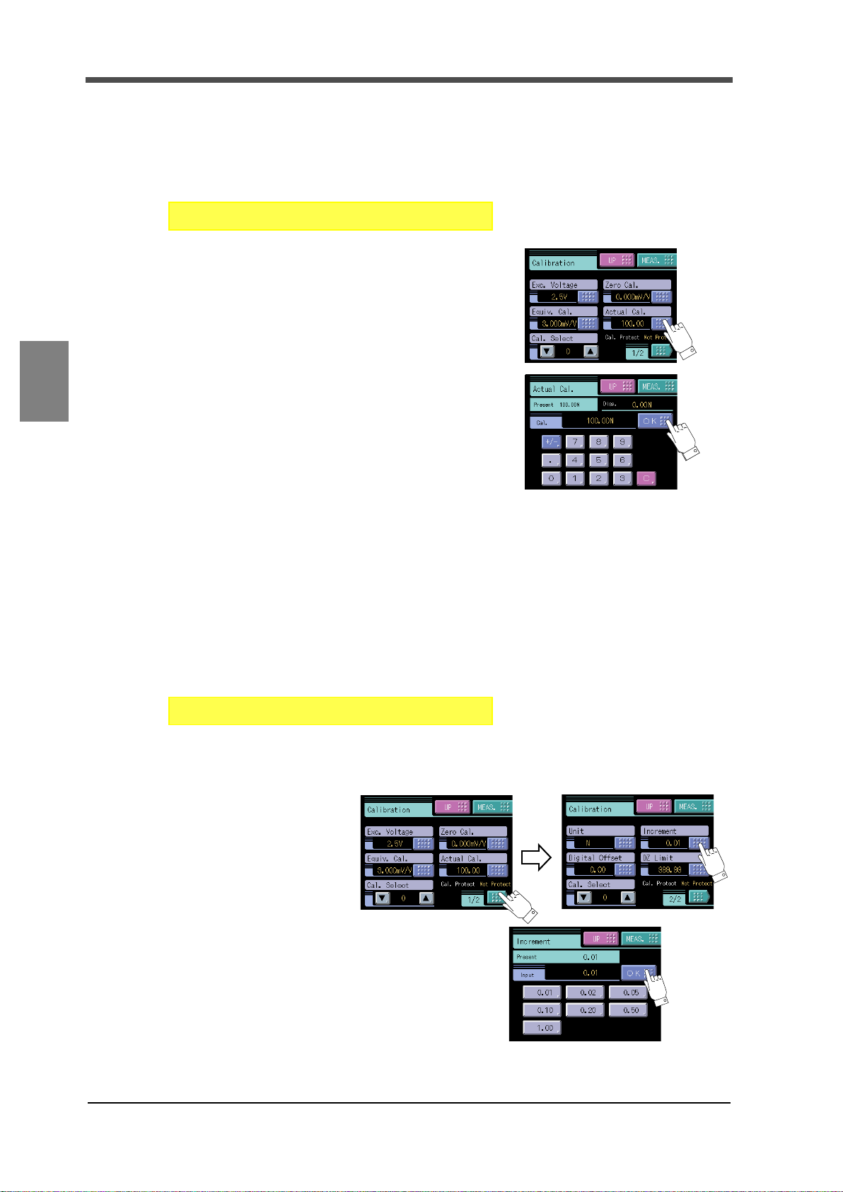
4-8. Actual Load Calibration
Set the actual load value under an actual load.
Setting range: -99999~99999(0 is excluded.)
How to set
1. Press the [SET.] button.
(refer to page 36)
2. Press the [Calibration] button.
(refer to page 36)
3. Press the [Actual Cal.] button.
4. Apply an actual load to the sensor, enter
the actual load value by the numerical
CALIBRATION
4-9. Increment (This step may be omitted if there is no change.)
keys and determine with the [OK] button.
Also, set the decimal place here. To
eliminate a decimal point, register by
inputting a numerical value and then
pressing the decimal point key at the end.。
Set the increment of the indicated value.
1 、 2 、 5 、 10 、 20 、 50 、 100(The display changes by the decimal place.)
How to set
1. Press the [SET.] button. (refer to page 36)
2. Press the [Calibration] button. (refer to page 36)
3. Select page 2,
and press the
[Increment]
button.
4. Select the
increment and determine with the
[OK] button.
38
38

4 CALIBRATION
Setting range: - 99999 - 99999
SET. Calibration Page 2
→→
SET. Calibration Page 2
→→
4-10.Digital Offset (This step may be omitted if there is no change.)
By using the digital offset function, the value obtained by subtracting the set value from the
indicated value is displayed. This function is convenient when zero cannot be obtained with no load
for some reason or for offsetting. When not using, set "0".
(Displayed value)=(Actual indicated value)-(Offset value)
How to set
1. Press the [SET.] button. (refer to page 36)
2. Press the [Calibration] button. (refer to page 36)
3. Select page 2,
and press the
[Digital Offset]
button.
Chapter
4
4. Enter the digital
offset value by the numerical keys and
determine with the [OK] button.
4-11.Digital Zero Limit
This is a load limit to allow digital zero.
When digital zero is executed, if the difference from the zero calibration point is larger than the
setting value, an error will result, and the indicated value will not be zeroed.
Setting range: 0 - 99999
How to set
1. Press the [SET.] button. (refer to page 36)
2. Press the [Calibration] button. (refer to page 36)
3. Select page 2,
and press the [DZ
CALIBRATION
(This step may be omitted if there is no change.)
Limit] button.
4. Enter the digital
zero limit value by the numerical keys
and determine with the [OK] button.
39
39
5 SETTING OF FUNCTIONS
5 SETTING OF FUNCTIONS
YESNO
D/Z
OFF
ON
Keep on for 1.0 msec. or more.
CAUTION
- When digital zero is performed, if the difference from the zero calibration
point exceeds the digital zero limit, the digital zero limit error will result.
Also, only the digital zero limit is subtracted.
- If the digital offset is set, even if digital zero is executed, zero will not
result. (Indicated value = -Setting value of digital offset)
- When digital zero reset is performed, the condition previous to correction
by digital zero is restored.
- Digital zero is reseted in case of power failure. Please set digital zero
again.
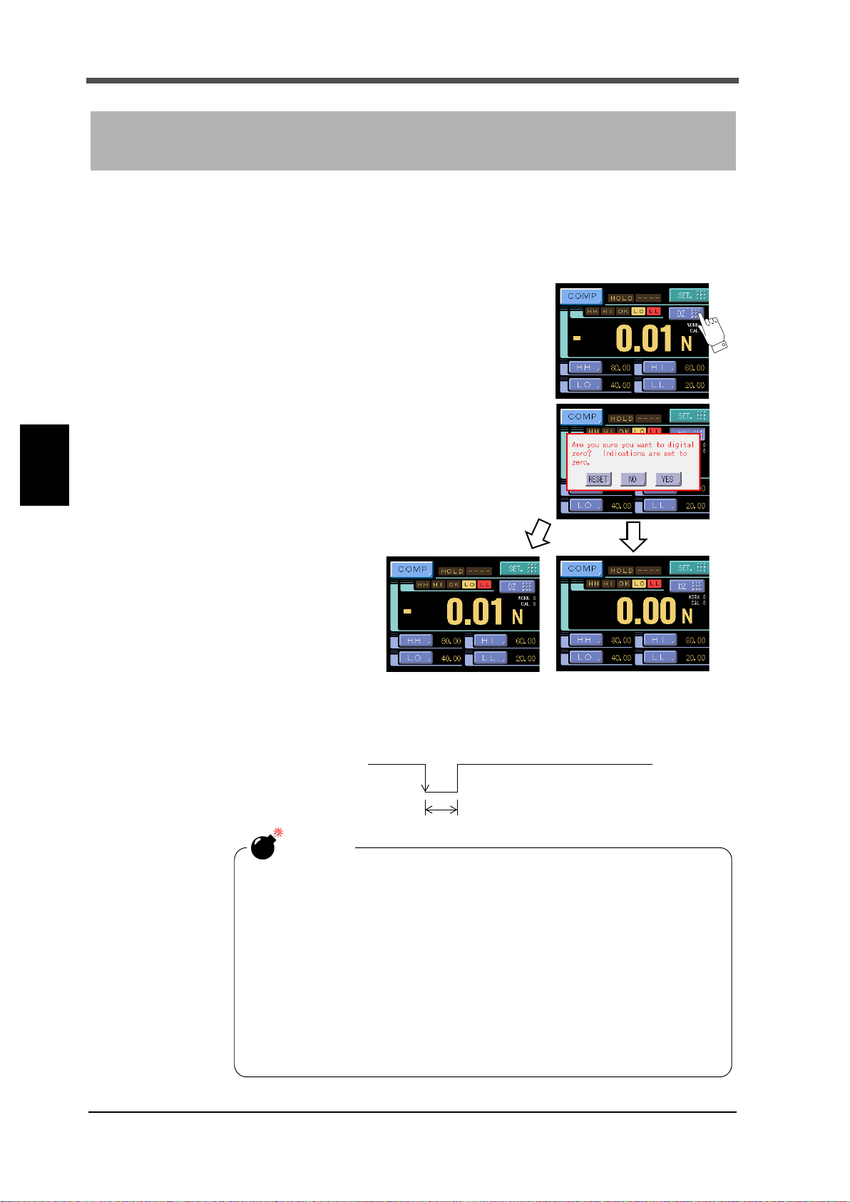
5-1. Digital Zero
Digital zero by means of Keys
Chapter
5
SETTING OF FUNCTIONS
The indicated values is forcedly zeroed.
1) Press the [DZ] button.in the ordinary display
screen (COMP・HOLD・GRAPH)
2) Press the [YES] button to
perform the digital zero. Press
the [NO] button to go back to
the previous screen without
executing digital zero.
Press the [RESET] button to
reset the digital zero.
Digital zero by means of External I/O signal (D/Z input)
The digital zero may be performed by short circuiting the D/Z to the COM2 on the rear panel signal
I/O terminal block.
40
40
5-2. Digital Filter
SET. Operation Page 1
→→
System Setting
→
SET. Operation Page 1
→→
System Setting
→
Setting
Indicated Value
50msec
Time
Setting Time
Count
SET. Operation Page 2
→→
System Setting
→
When the time is 0.0 sec. and the width is 00 markings, stable is not detected.
Stability detection by Motion Detect is closely related to the SI/F print (stable
value) function and comparison timing. For details, see "5-8.SI/F Print Out"on
page 43 and " ■ Comparison timing"on page 46.
The digital filter is a function for reducing drifts of the indicated value by means of a moving
average of data converted from analog to digital. With an increase in the number of filterings, the
indicated value becomes more stable, but the response to inputs becomes slower.
Number of settings: OFF, 2 - 999
How to set
5-3. Analog Filter
A low-pass filter is provided for filtering input signals from the strain-gage sensor and canceling
noise components.
The cut-off frequency can be selected in a range between 30Hz and 1000Hz. With an increase in the
cut-off frequency, the response becomes faster, but noise components may be indicated.
Cut-off frequency: 30Hz, 100Hz, 300Hz, 1000Hz
5 SETTING OF FUNCTIONS
How to set
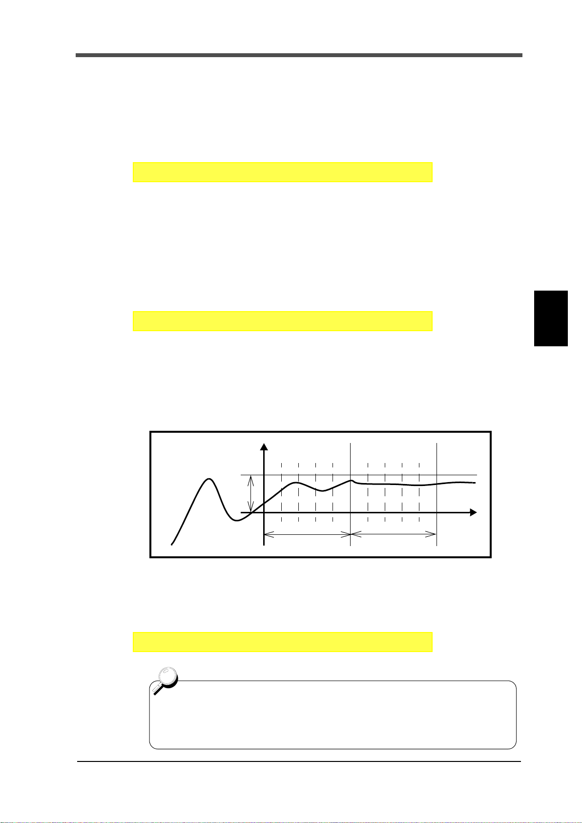
5-4. Motion Detect (MD)
Enter the parameters to detect stable.
If the difference between the current indicated value and the 50-msec-previously indicated value is
less than the set count and the duration of the condition is more than the set time, the indicated
value is regarded to be stable.
Setting range:
Chapter
5
SETTING OF FUNCTIONS
MD (Time): 0.0 - 9.9 sec.
MD (Count): 0 - 99 count
How to set
41
41
Chapter
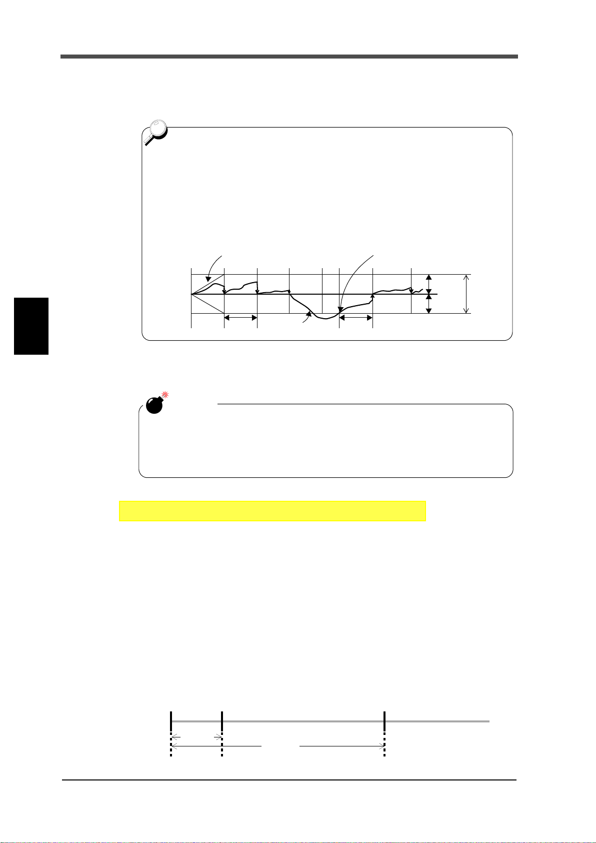
・When displacement of the zero point is within the set count of tracking and it
continues more than the set time, it is automatically made zero by Zero
Tracking function.
・The time (tracking delay) is set in the range of 0.1 - 9.9 sec., and the band
(tracking band) is set in the range of 01 to 99.
If the time is set at 0.0 sec. and the band at 00, the zero tracking function
does not work.
Boundary of zero track
DELAY
Indicated value
+COUNT
-COUNT
BAND
+
0
-
DELAY
Band=count×2
From the point when it returned within the range,
counting will be resumed.
CAUTION
Zero tracking is equal to digital zero functioning automatically.
Therefore, the digital zero limit is also monitored.
Zero tracking does not function when the indicated value has already
exceeded the tracking band.
SET. Operation Page 2
→→
System Setting
→
Bright Dark
10 min.
60 min.
Light Out
5 SETTING OF FUNCTIONS
5-5. Zero Tracking (ZT)
Gradual changes in the zero point due to drifts etc., are automatically tracked for correction.
5
SETTING OF FUNCTIONS
Setting range:
ZT (Time): 0.0 - 9.9 sec. ZT (Count): 0 - 99 count
How to set
5-6. Backlight
This function changes the brightness of the backlight when touch screen has not been used for
certain period of time.
The ON time ( lighting time of the backlight) and the Low time ( bright→dark switching time of the
backlight) are set up.
When you use it in the state which a display is always in sight, set the ON time to 0 minutes.
When you want the backlight always bright, set 0 minutes for both the ON time and the Low time.
The backlight is turned bright by touching the panel when the backlight is turned off or it is dark.
Ex.) Set 60 minutes to ON time, 10 minutes to Low time.)
42
42

Setting range: 00 - 99 minutes (with both time)
SET. Operation Page 1
→→
System Setting
→
SET. Operation Page 1
→→
System Setting
→
SI/F print out (setting to MD) is not performed under the following conditions.
- Motion Detect Time: 0.0 sec., Count: 0.0 of divisions is set.
Also, the indicated value is not held under the following conditions.
- Hold Mode When any items except Tracking is selected.
Indicated Value
Near Zero
0
Stab le
Near Zero
ON
ON
ONON
OFF
OFF
OFF
Autmatic Printing
↑
Hold
1.5Seconds
Time
ON
Hold function……
Indicatid Value
SI/F
Compariosn
+
Sensor input value
Near Zero
0
Time
Stable
Near Zero
ON
ON
ONON
OFF
OFF
OFF
Autmatic Printing
↑
Hold
1.5Seconds
ON
-
Indicated
Sensor input value
Output signal
Val ue
How to set
5-7. Display Language Selection
The display language of the F372A is selectable between Japanese and English.
Setting range: JPN(日): Japanese, ENG(英): English
How to set
5 SETTING OF FUNCTIONS
5-8. SI/F Print Out
- OFF
Real time values and hold values are output in the GROSS area and NET area, respectively.
- MD
By this function, the indicated value is automatically printed to the UNIPULSE printer coupled
with the F372A through the SI/F when the indicated value is stable. (Set the stable parameters by
the Motion Detect.)
When Near Zero is OFF, Indicated value is held until Near Zero turns ON after stable turned ON.
(Hold will be released when 1.5 sec. is passed after Near Zero is ON.) The output format is the
same as in the setting of "OFF".
Chapter
5
SETTING OF FUNCTIONS
43
43

Chapter
SET. Operation Page 1
→→
System Setting
→
SET. Operation Page 2
→→
System Setting
→
Time
Indicated value
HI Limit
LO Limit
HI
LO
OFF
ON
OFF
ON
HH Limit
LL Limit
OFF
ON
OFF
ON
HH
LL
OFF
ON
OK
5
5 SETTING OF FUNCTIONS
- HOLD
At hold-off time, the held value is automatically printed to the UNIPULSE printer coupled with the
F372A through the SI/F. At hold-off time, hold values and real time values are output in the
GROSS area and NET area, respectively. Others are the same as in the setting of "OFF".
Setting range: OFF, MD, HOLD
How to set
5-9. Indicate Color
The indicated value display color can be changed. By setting Comp.(Comparison Result), the
indicated value display color changes following the comparison status.
OK green
HI, LO yellow
HH, LL red
Setting range: Yellow, Green, Blue, Comp.
How to set
SETTING OF FUNCTIONS
5-10.Comparison Functions
By the comparison function, the HI limit and LO limit values are set, and when the indicated value
exceeds the HI limit, the HI output is turned on, and when the indicated value falls below the LO
limit, the LO output is turned on. Also, HH limit and LL limit values may be set outside the HI-LO
limit comparison. When the indicated value exceeds the HH limit, the HH output is turned on, and
when the indicated value falls below the LL limit, the LL output is turned on. When the HI, HH, LO
and LL outputs are all off, the OK output is turned on.
〈HI/LO output conditions〉 HI: Indicated value>HI limit value
〈HH/LL output conditions〉 HH: Indicated value>HH limit value
〈OK output conditions〉 OK: All conditions of HH, HI, LO and LL are off.
LO: Indicated value <LO limit value
LL: Indicated value<LL limit value
44
44

■HI limit / LO limit / HH limit / LL limit
SET. Comp. Setting Page 1
→→
Work Setting
→
Simple setting call
Press any of the [HH], [HI], [LO] and [LL] buttons at the bottom of the indicated
value display screen to go direct to the entry screen.
SET. Comp. Setting Page 1
→→
Work Setting
→
Hysteresis setting value is common to all HI limit value.
How to set
5 SETTING OF FUNCTIONS
■Hysteresis
The hysteresis value may be determined so as to allow a margin for timing the turning off of the HI-
LO limit comparison. Normally, it is turned on when the indicated value exceeds the HI limit and is
turned off when the indicated value falls below it. However, by setting the hysteresis, it is turned off
when the indicated value falls below the HI limit further lowered by the hysteresis value.
This function is effective to prevent chattering in such a case where signals fluctuate (vibrate)
subtly.
〈Comparison conditions〉
- HI limit
ON condition: indicated value>HI limit value
OFF condition: indicated value≦(HI limit value-hysteresis value)
- LO limit
ON condition: indicated value<LO limit value
OFF condition: indicated value≧(LO limit value+hysteresis value)
- HH limit
ON condition: indicated value>HH limit value
OFF condition: indicated value≦(HH limit value-hysteresis value)
- LL limit
ON condition: indicated value<LL limit value
OFF condition: indicated value≧(LL limit value+hysteresis value)
Chapter
5
SETTING OF FUNCTIONS
Setting range: 0 - 9999
How to set
45
45

Chapter
HI Limit
LO Limit
+
0
Hysteresis Range
Time
HI Output
HI Status Display
LO Output
LO Status Display
OK Status Display
Output ON
Stat us ON
Output OFF
Stat us OFF
Status ON Status ON
Output ON
Status ON
Output ON
Status ON
-
Output OFF
Stat us OFF
Output OFF
Status OFF
Indicated Value
OK Output
(Exsample :
HI Output and LO Output and OK output)
Near-zero ON/OFF is closely related to the SI/F Print Out (stable) and Comparison
timing.
For details, see the sections "SI/F Print Out" on page 43 and "Comparison timing"
on page 46.
SET. Comp. Setting Page 2
→→
Work Setting
→
SET. Comp. Setting Page 2
→→
Work Setting
→
5 SETTING OF FUNCTIONS
- Hysteresis operation
5
SETTING OF FUNCTIONS
■Near zero
By this function, it is detected that the indicated value is near zero.
Near-zero ON: | indicated value | ≦ near zero set value
Near-zero OFF: | indicated value |> near zero set value
Setting range: 00000 - 99999
How to set
■Comparison timing
Set the operating condition of HI-LO limit comparison. Select the condition from the following.
ALL: HI-LO limit comparison is performed continuously.
MD: HI-LO limit comparison is performed when the indicated value is stable.
Set the stable parameters by the stable operation.
46
46
NZ: HI-LO limit comparison is performed when the indicated value is not near zero.
MD+NZ:
Set the near zero parameters by the near zero operation.
HI-LO limit comparison is performed when the indicated value is stable and not near zero.
HOLD: HI-LO limit comparison is performed when the indicated value is held.
How to set

5 SETTING OF FUNCTIONS
A2 A3 A4 A5 A6
H4 / L0 HI-4 HI-3 OK HI-2 HI-1
H3 / L1 HI-3 HI-2 OK HI-1 LO
H2 / L2 HH HI OK LO LL
H1 / L3 HI LO-1 OK LO-2 LO-3
H0 / L4 LO-1 LO-2 OK LO-3 LO-4
Mode HI limit operation LO limit operation
H4 / L0 HI-1 to HI-4 None
H3 / L1 HI-1 to HI-3 LO
H2 / L2 HH, HI LO, LL
H1 / L3 HI LO-1 to LO-3
H0 / L4 None LO-1 to LO-4
The HI limit output is turned on when the indicated value becomes larger than the set value.
The LO limit output is turned on when the indicated value becomes smaller than the set value.
SET. Comp. Setting Page 2
→→
Work Setting
→
[HI-0, LO-4]
[HI-1, LO-3]
[HI-2, LO-2]
[HI-3, LO-1]
[HI-4, LO-0]
[Setting] [Comparison]
■Comparison output selection
The number of HI-LO limits can be changed.
Correspondence between comparison screens and external I/O output terminals.
How to set
Chapter
5
SETTING OF FUNCTIONS
47
47

5 SETTING OF FUNCTIONS
Hold values
Alarm HI limit
HI limit
Real Time values
LO limit
Alarm LO limit
SET. Comp. Setting Page 2
→→
Work Setting
→
- Since both the alarm HI limit and LO limit are set to be invalid as initial values, reset
them for use.
- Since the alarm HI limit and LO limit are independent, use of only one of them is also
possible.
SET. Hold Setting Page 1
→→
Work Setting
→
■Alarm HI and LO limits
The alarm HI and LO limits are always compared with sensor input values. By this function,
whether the indicated value becomes abnormal during hold can be monitored.
If the indicated value exceeds the alarm HI limit or falls below the alarm LO limit, an OVERLOAD
error will result, and the RUN output turns OFF. (Refer to "Error Display List" on page 88)
Alarm HI limit: -99999 - 99999 (invalid at 99999 (initial value))
Alarm LO limit: -99999 - 99999 (invalid at -99999 (initial value))
Chapter
5
SETTING OF FUNCTIONS
5-11.Hold Functions
■Hold setting --- Common ---
Hold mode
How to set
By the hold function, a specific point in a waveform is taken out for HI-LO limit comparison.
The operation of each hold will be described in detail.
The F372A includes 10 hold modes as shown in the table below.
In the peak, valley, peak-to-peak and average modes, section setting is required. Select all section,
external signal, external signal+time, level+time, level.
When not using any hold function, be sure to set the hold mode to OFF.
(In the OFF state, hold operation is not performed but input values are always displayed.)
Hold mode Hold section
OFF
Sample None
Peak
Valley
P-P
Average
Rel. Max
Rel. Min
Rel. Dif
Inf. Pnt
How to set
48
48
Required
None
-
*There is a section
setup.
- All
- EXT
- EXT+TM
- LVL+TM
*
- LVL
* Selectable only for
Peak or Valley.

5 SETTING OF FUNCTIONS
Simple setting call
Press the [MODE] button at the bottom of the indicated value display screen to go direct to the
hold mode entry screen.
SET. Hold Setting Page 1
→→
Work Setting
→
SET. Hold Setting Page 1
→→
Work Setting
→
To perform hold operation simply by the external section signal (SECTION) without using
the hold start level in the Relative Maximum / Relative Minimum / Relative Difference /
Inflection Point hold mode, change External + Level to External Only in the Detection Start
Condition setting.
SET. Hold Setting Page 2
→→
Work Setting
→
SET. Hold Setting Page 1
→→
Work Setting
→
Section time
If you set the hold section setting in the hold function setting to external signal+time or level+time,
set the time.
Setting range: 0.001 - 9.999 sec.
How to set
Hold start level
Set the start level in the case where the Section setting is Level + Time or Level for Peak, Valley, P-
P, or Average hold or where the Detection Start Condition is External + Level for Relative
Maximum, Relative Minimum, Relative Difference, or Inflection Point hold.
Setting range: -99999 - 99999
How to set
Hold stop level
Set the hold stop level in the case where the Section setting is Level for Peak or Valley hold.
Chapter
5
SETTING OF FUNCTIONS
Setting range: -99999 - 99999
How to set
Detection start condition
49
Setting range: Ext+Level, Ext Only
How to set
49

Chapter
- Passed: Detection starts when the indicated value passes Hold start level.
- Passed HI: Detection starts when the indicated value passes Hold start level in the direction from
smaller toward larger values.
- Passed LO: Detection starts when the indicated value passes Hold start level in the direction from
larger toward smaller values.
The actual hold point
t
w
CAUTION
- This does not work for other
holds.
When the hold point shift is set at 8, the
data eight pieces before the actual hold
point is held.
When the hold point shift is set at +1,
the data one piece after the actual
hold point is held. However, it is not
held if the destination is outside the
set Section.
SET. Hold Setting Page 2
→→
Work Setting
→
A
B
O
P
Q
2X
X
1.5X 3X
True Relative
True Relative
Relative
Relative
A
X
B
Relative
Relative Minimum
Maximum
Minimum
Maximum
Minimum
Maximum
5 SETTING OF FUNCTIONS
Level detection conditions
(hold section setting; Level + Time or Level, or detection start condition; External + Level)
Setting range: Passed, Passed HI, Passed LO
Hold point shift
In the "sample hold" and "inflection point hold", the sampling data is held as it is shifted back or
forth by the numerical value set under Sample Removal Value / Inflection Removal Value.
Setting range: -999 - 999
5
SETTING OF FUNCTIONS
50
50
How to set
■Hold setting --- Relative (Maximum / Minimum / Difference) ---
If you select the relative maximum and relative minimum hold in the hold function setting, set the
relative maximum and relative minimum value detection parameters "relative minimum count" and
"relative magnification".
Set referring to the principle of operation only when the value cannot be held successfully with the
factory settings or when further adjustments are required.
Detection of relative values
The logic of detecting the relative values is given below.
First, when difference X between point A and point B
is larger than the minimum count, point A is judged to
be the relative maximum value and point B is judged to
be the relative minimum value.
After that, when the load exceeds difference X
multiplied by the relative magnification (1/4 to 4), A,
B, and the difference between A and B are held in
relative maximum hold, relative minimum hold, and
relative difference hold, respectively, at O, P, Q, etc.
If the minimum count is too small, when the waveform
includes noise as shown on the left-hand side, the noise
is regarded as the relative maximum value or relative
minimum value and a correct value may not be held. In
such a case, set the minimum count somewhat large.

5 SETTING OF FUNCTIONS
SET. Hold Setting Page 1
→→
Work Setting
→
SET. Hold Setting Page 1
→→
Work Setting
→
D
C
C
AB
a
Input Signal
Inflection point
Held as an inflection point if
D > inflection judgment value.
A : Inflection front sope time
B : Inflection rear sope time
D : The amount of change
SET. Hold Setting Page 2
→→
Work Setting
→
SET. Hold Setting Page 2
→→
Work Setting
→
Relative minimum count
Setting range: 0001 - 99999
How to set
Relative magnification
Setting range: ×0.25, ×0.50, ×0.75, ×1.00, ×1.25, ×1.50, ×2.00, ×3.00, ×4.00
How to set
■Hold setting --- Inflection point ---
If you select the inflection point hold in the hold function setting, set the inflection point detection
parameters "inflection minimum slope", "inflection front sope time" and "inflection rear sope time".
Set referring to the principle of operation only when the value cannot be held successfully with the
factory settings or when further adjustments are required.
Detection of the inflection point
The logic of detecting the inflection point is given below.
Assuming that the remainder obtained by subtracting the amount of change C of the indicated value over
A from the amount of change of the indicated value over B is D, when the amount of change D exceeds
the inflection minimum slope, point a is held as an inflection point.
If there are two or more inflection points in the hold section, the point having a larger change is held.
The inflection point is normally detected by A=B, but it may easily be detected with A<B where the
slope is gradual.
Chapter
5
Inflection minimum slope
Setting range: 00001 - 99999
How to set
Inflection front slope time and Inflection rear slope time
Setting range: 0≦Inflection front (rear) slope time≦990
How to set
SETTING OF FUNCTIONS
Inflection front slope time+Inflection rear slope time≦1000
51
51

Chapter
Inflection front (rear) slope time setting is the number of samplings. Since the F372A's
sampling speed is 2000 times/sec., one sampling is 0.5msec.
Therefore, setting of the interval at 100 means setting of 50msec.
Load change time
True inflection
Inflection
point
point
100
20
10
0
100msecA100msec
B
D = 80
C = 10
①
②
5 SETTING OF FUNCTIONS
Caution regarding inflection point hold
If the detection Inflection front sope time and Inflection
rear sope time are set too short, fine load changes may be
detected as shown in the illustration on the left-hand side,
so that a correct value cannot be held.
In this case, set the detection inflection rear sope time
large enough to bring it as close to the load change time as
possible, and also set the inflection minimum slope large
according to the amount of change at that time, so that the
inflection point is held at a correct position.
5
Example of inflection point hold setting
● Example of ideal waveform setting
SETTING OF FUNCTIONS
① Set the load change time (between the inflection point and when the change stops) to
② Set the same value as inflection rear sope time to inflection front sope time.
③
● If the inflection point cannot be located successfully
inflection rear sope time. In the example, it is set to 200 since it is 100 msec.
Set load D obtained by subtracting load C changing with inflection front sope time from the
load changing with inflection rear sope time to the inflection minimum slope.
In the example, set load change D=80 obtained by subtracting load C=10 changing with A
from load 90 changing with B to the inflection minimum slope.
However, since an inflection point is not judged until load change D exceeds the inflection
minimum slope, actually set the inflection minimum slope a slightly smaller than D.
① When holding above the inflection point and moving downward
1) It is considered that the inflection minimum slope is small with
respect to load change D. Set the inflection minimum slope
larger.
2) If lowering is insufficient in 1), increase inflection front sope
time.
② When holding below the inflection point and moving upward
52
52
inflection rear sope time is too long and the inflection minimum
slope is too large.Shorten inflection rear sope time and decrease
the inflection minimum slope.

5 SETTING OF FUNCTIONS
SET. Hold Setting Page 2
→→
Work Setting
→
About the maximum average value detection time
Although the detection section is specified by the SECTION signal, etc., detection
cannot be carried out exceeding the maximum average value detection time set
according to the
average sample number
. If the maximum average value detection
time is exceeded, detection ends automatically, when the average value is held.
Indicated Value
t2
t3
t1
Sensor Input Value
Hold Section
Fixed
t
+
T/H
HI-LO Limit
Judging Output
H/E
OFF
ON
OFF
ON
OFF
ON
HOLD
OFF
ON
Button
HOLD
Status Display
Status Display
ONBlink Blink
OFF
----
■Hold setting --- Average value ---
Average sample number
In average hold, the average in each sampling can be detected for up to 5 seconds. Then, if the
average sample number is set at 2 or more, the representative value of the sampling values by the
set number (average by the number) is adopted as the sampling data used for average calculation.
The maximum average value detection time with the setting “1” is 5 sec., but the average value
detection time can be extended by this setting.
Maximum average value detection time=Average sample number×5 [sec.]
where the number of updates of the average value will decrease.
Number of updates of the average value
=2000 /
Average sample number [times/sec.
Setting range: 1 - 999 times
How to set
■Hold operation
Sample hold
When the T/H signal is inputted, a desired point is held, and the H/E output is turned on.
Hold of the value continues as long as the T/H signal is on.
t1: A delay time between the instant
when the T/H signal is inputted and
the instant when the indicated value
is held
1.0ms (max.)
]
Chapter
5
SETTING OF FUNCTIONS
53
t2: A delay time between the instant
when the T/H signal is released and
the instant
when the indicated value returns to
tracking
1.0ms (max.)
t3: A minimum reset signal width
required for releasing the hold
1.0ms (min.)
53
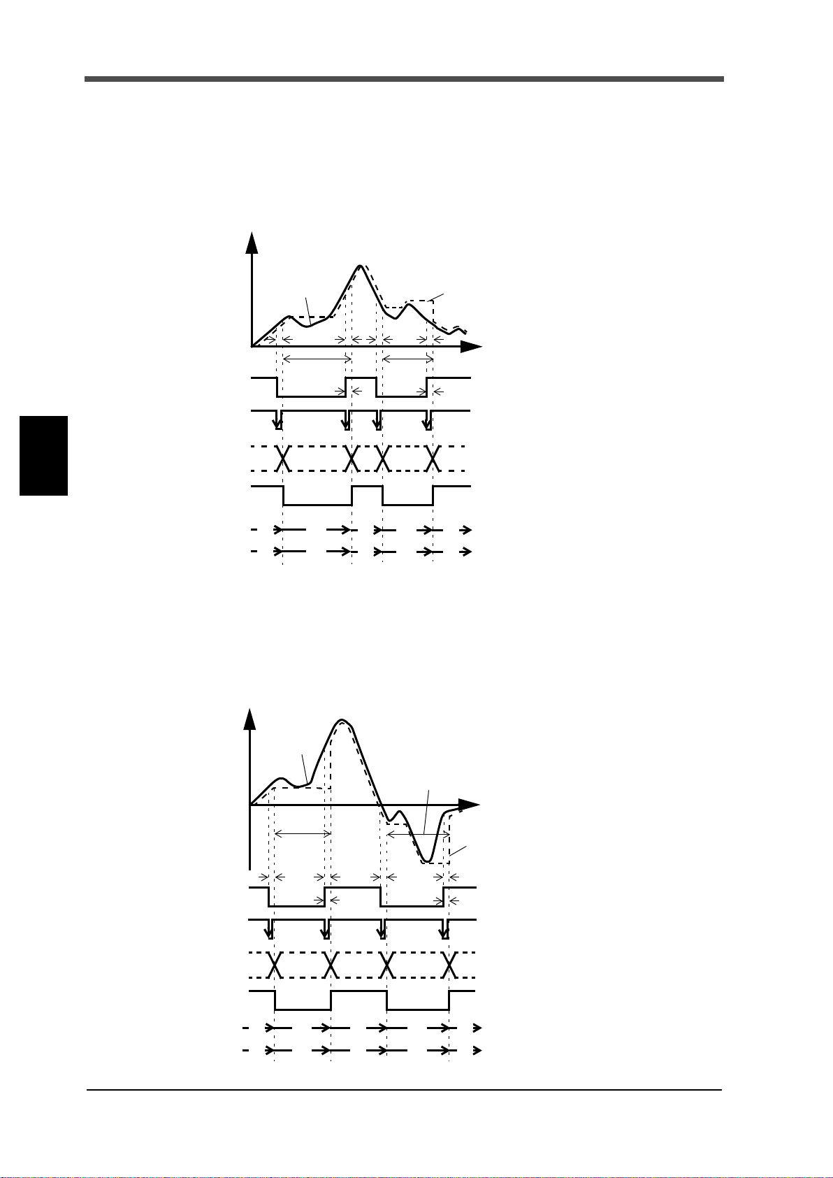
5 SETTING OF FUNCTIONS
Indicated Value
t2
t3
Sensor Input Value
Detection
t
+
T/H
HI-LO Limit
Judging Output
H/E
Detection
t1t2t1
t3
OFF
ON
OFF
ON
OFF
ON
OFF
ON
Status Display
PEAK
Status Display
ON
Blink Blink
OFF ON
OFF
OFF
OFF
OFF
OFF
HOLD
Button
Undetermind
section (Note)
Undetermind
section (Note)
Hold Section
Hold Section
HOLD
Indicated Value
t2
t3
Sensor Input Value
Detection
t
+
T/H
HI-LO Limit
Judging Output
H/E
Detection・Hold Section
t1t2t1
t3
OFF
ON
OFF
ON
OFF
ON
OFF
ON
HOLD
Status Display
VLLY
Status Display
ON
Blink Blink
OFF ON
OFF
OFF
OFF
OFF
OFF
HOLD
Button
Undetermind
section (Note)
Undetermind
section (Note)
Hold Section
Peak hold
Chapter
5
SETTING OF FUNCTIONS
The maximum value (peak) in the positive direction of the specified section is held.
The section is specified by the setting of “all section”, “external signal”, “external signal+time”,
“level+time”, or “level”.
(Example) All section peak hold
t1: A delay time between the instant
when the T/H signal is inputted and the
instant when the indicated value is held
1.0ms (max.)
t2: A delay time between the instant
when the T/H signal is released and the
instant when the indicated value returns
to tracking
1.0ms (max.)
t3: A minimum reset signal width
required for releasing the hold
1.0ms (min.)
Note: During the undetermined section, the
judging output varies with fluctuations in the
input waveform. However, the H/E output
remains on during the undetermined section.
Read the judging result when the indicated
value becomes stable (immediately before the
T/H signal rises).
Valley hold
The maximum value (valley) in the negative direction of the specified section is held.
The section is specified by the setting of “all section”, “external signal”, “external signal+time”,
“level+time”, or “level”.
(Example) All section valley hold
54
54
t1: A delay time between the instant
when the T/H signal is inputted and the
instant when the indicated value is held
1.0ms (max.)
t2: A delay time between the instant
when the T/H signal is released and the
instant when the indicated value returns
to tracking
1.0ms (max.)
t3: A minimum reset signal width
required for releasing the hold
1.0ms (min.)
Note: During the undetermined section, the
judging output varies with fluctuations in the
input waveform. However, the H/E output
remains on during the undetermined section.
Read the judging result when the indicated
value becomes stable (immediately before the
T/H signal rises).

5 SETTING OF FUNCTIONS
Indicated Value
Sensor Input Value
Detection・Hold Section
Undetermind
t
+
T/H
HI-LO Limit
Judging Output
H/E
t2
t1
t3
Standard Line
(Hold Section Only)
Indicated Value = 0
Indicated Value=0
OFF
ON
OFF
ON
OFF
ON
HOLD
OFF
ON
Button
HOLD
Status Display
P-P
Status Display
ON
Blink
OFF
OFF
OFF
OFF
section (Note)
Real Time
Indicated Value
t
+
T/H
H/E
Fixed
SECTION
OFF
ON
OFF
ON
OFF
ON
OFF
ON
Undetermind
t1 t2 t3
Detection
Hold Section
OFF
ON
HOLD
Button
HOLD
Status Display
AVE
Status Display
ON
Blink ON
OFF ON OFF
OFF
OFF
values
HI-LO
Judging
Limit
Output
Section
The detection section is limited by the maximum average value detection time set
according to the “Average sample number”.
For details, see the section on "Average sample number"on page 53.
Peak-to-Peak (P-P) hold
The difference value between the peak and valley over the specified section is held.
The section is specified by the setting of “all section”, “external signal”, “external signal+time”, or
“level+time”.
(Example) All section Peak-to-Peak (P-P) hold
t1: A delay time between the instant
when the T/H signal is inputted and the
instant when the indicated value is held
1.0ms (max.)
t2: A delay time between the instant
when the T/H signal is released and the
instant when the indicated value returns
to tracking
1.0ms (max.)
t3: A minimum reset signal width
required for releasing the hold
1.0ms (min.)
Note: During the undetermined section, the
judging output varies with fluctuations in the
input waveform. However, the H/E output
remains on during the undetermined section.
Read the judging result when the indicated
value becomes stable (immediately before the
T/H signal rises).
Chapter
5
Average hold
The average value of the sampling values over the specified section is calculated and updated to
perform comparison operation. The section is specified by the setting of “all section”, “external
signal”, “external signal+time”, or “level+time”.
(Example) Externally specified section average value hold
55
t1:
A delay time between the instant
when the SECTION signal is inputted
and the instant when detection
is
performed.
1.0ms (max.)
t2: A delay time between the instant
when the SECTION signal is released
and the instant when the value to be
held is determined
1.0mS (MAX.)
t3: A minimum reset signal width
required for releasing the hold
1.0ms (min.)
55
SETTING OF FUNCTIONS

Chapter
Indicated
t3
Sensor Input Value
Detection
t
+
Hold Section
Fixed
SECTION
t1
Hold Start Level
T/H
H/E
OFF
ON
OFF
ON
OFF
ON
OFF
ON
HOLD
INF
ON
Blink
OFF
OFF
OFF
OFF
HOLD
Button
OFF
ON
ON*
ON*
Status Display
Status Display
Val ue
HI-LO Limit
Judging Output
*When it was not possible to hold correctly, both HOLD and INF status display are blinked.
t3
Sensor Input Value
Detection
t
+
Hold Section
Fixed
SECTION
t1
T/H
H/E
OFF
ON
OFF
ON
OFF
ON
OFF
ON
ON
Blink ON*
OFF
OFF
OFF
OFF
HOLD
Button
OFF
ON
MAX
ON*
HOLD
Status Display
Status Display
Indicated
Val ue
Hold Start Level
HI-LO Limit
Judging Output
(Rel. Min: MIN)
(Rel. Dif : DIF)
*When it was not possible to hold correct ly, both HOLD and MAX(MIN,DIF) status display are blinked.
5 SETTING OF FUNCTIONS
Inflection point hold
Detection starts when the SECTION signal is inputted and also the Level detection conditions is
met in comparison of the Hold Start Level and indicated value. Detection is performed as long as
the SECTION signal is ON.The Hold is released by turning on the T/H signal as a reset signal.
The H/E output signal is on between the instant when the hold starts and the instant when the T/H
signal is turned on. The next detection is started when the SECTION signal is turned on again even
if the T/H signal is not turned on.
If you want to perform detection simply by the SECTION signal without using the Hold Start
Level, set the Detection Start Condition to "External Only".
(Example) Inflection point hold
t1: A delay time between the instant
when the indicated value meets the
Hold Start Level under the Level
detection conditions and the instant
when detection starts.
t3: A minimum reset signal width
required for releasing the hold
1.0ms (min.)
5
SETTING OF FUNCTIONS
Relative maximum, Relative minimum, Relative difference hold
The way of starting detection is the same as Inflection Point hold.
(Example) Relative maximum hold
t1: A delay time between the instant
when the indicated value exceeds the
Hold Start Level and the instant when
hold is detected.
t3: A minimum reset signal width
required for releasing the hold
1.0ms (min.)
56
56
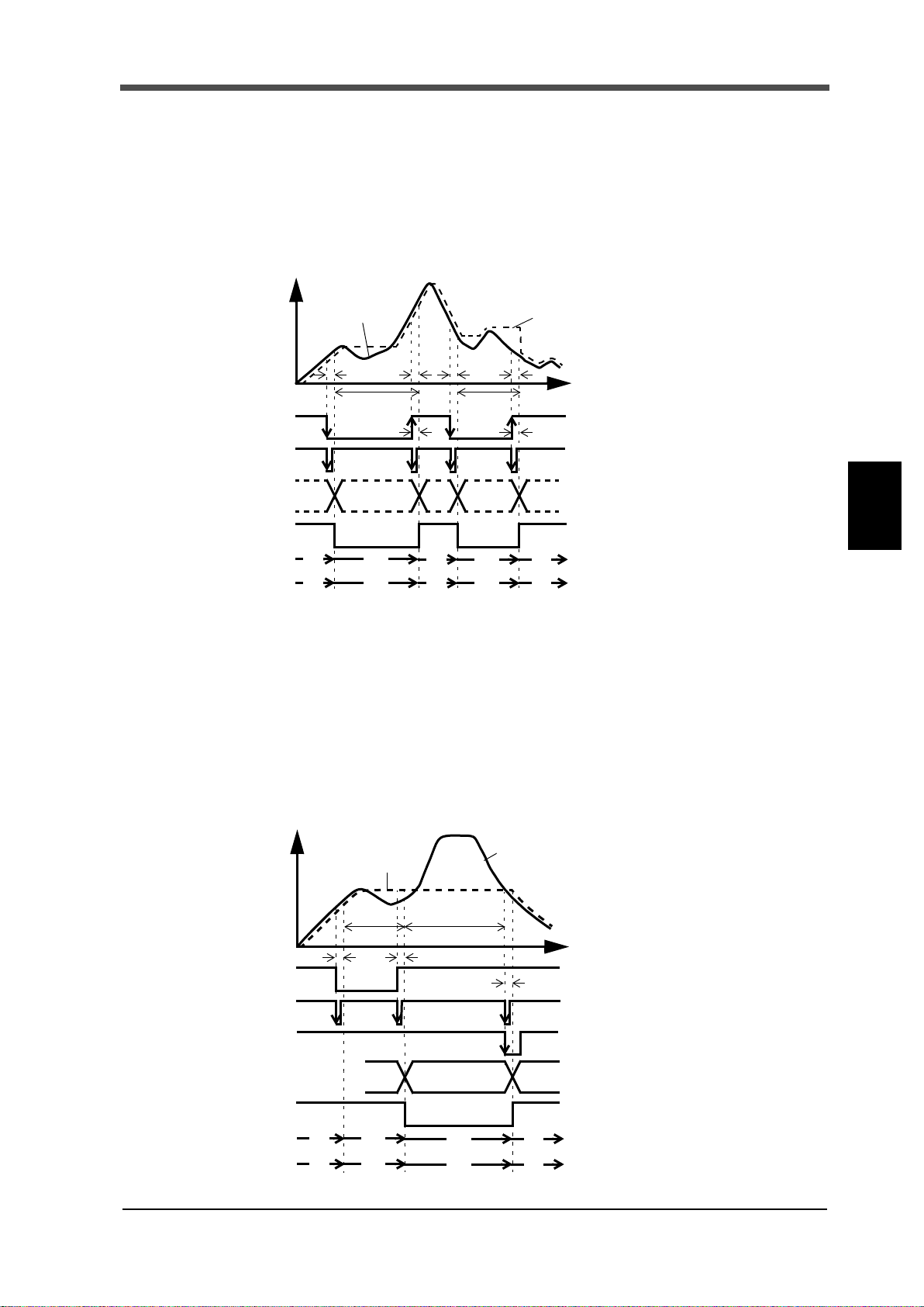
5 SETTING OF FUNCTIONS
Indicated Value
t2
t3
Sensor Input Value
t
+
T/H
H/E
t1
t2t1
t3
OFF
ON
OFF
ON
OFF
ON
OFF
ON
HOLD
Status Display
PEAK*
Stat us Dis pl ay
ON
Blink Blink
OFF ON
OFF
OFF
OFF
OFF
OFF
HOLD
Button
HI-LO Limit
Judging Output
Undetermind
section (Note)
Undetermind
section (Note)
*The status display changes depending on the hold mode.
Detection
Hold Section
Detection
Hold Section
Indicated Value
t3
Sensor Input Value
Detection
t
+
T/H
H/E
Hold Section
t2
t1
Fixed
SECTION
OFF
ON
OFF
ON
OFF
ON
OFF
ON
OFF
ON
ON
Blink ON
OFF ON
OFF
OFF
OFF
HOLD
Button
HOLD
Status Display
PEAK*
Stat us Dis pl ay
*The status display changes depending on the hold mode.
HI-LO Limit
Judging Output
■
How to specify the hold detection section(Peak, Valley, P-P, Average)
All section
By this method, the hold detection section is externally specified by the T/H signal.
Detection starts with the T/H signal ON to perform each hold operation.
According to the ON/OFF state of the T/H signal, detection and tracking are repeated. There is no
fixed hold section.
(Example) All section peak hold
t1: A delay time between the instant
when the T/H signal is inputted and the
instant when the indicated value is held
1.0ms (max.)
t2: A delay time between the instant
when the T/H signal is released and the
instant when the indicated value returns
to tracking
1.0ms (max.)
t3: A minimum reset signal width
required for releasing the hold
1.0ms (min.)
Note: During the undetermined section, the
judging output varies with fluctuations in the
input waveform. However, the H/E output
remains on during the undetermined section.
Read the judging result when the indicated
value becomes stable (immediately before the
T/H signal rises).
Chapter
5
57
External signal
By this method, the hold detection section is externally specified by the SECTION signal to
maintain the hold value until the reset signal is turned on.The hold is released by turning on the T/H
signal as a reset signal. The next detection is started when the SECTION signal is turned on again
even if the T/H signal is not turned on.
The H/E output signal is on between the instant when the SECTION signal is turned off and the
instant when the T/H signal is turned on.
(Example) Externally specified section peak hold
t1: A delay time between the instant
when the SECTION signal is inputted
and the instant when the value to be
held is detected
1.0ms (max.)
t2: A delay time between the instant
when the SECTION signal is released
and the instant when the value to be
held is determined
1.08ms (max.)
t3: A minimum reset signal width
required for releasing the hold
1.0ms (min.)
SETTING OF FUNCTIONS
57
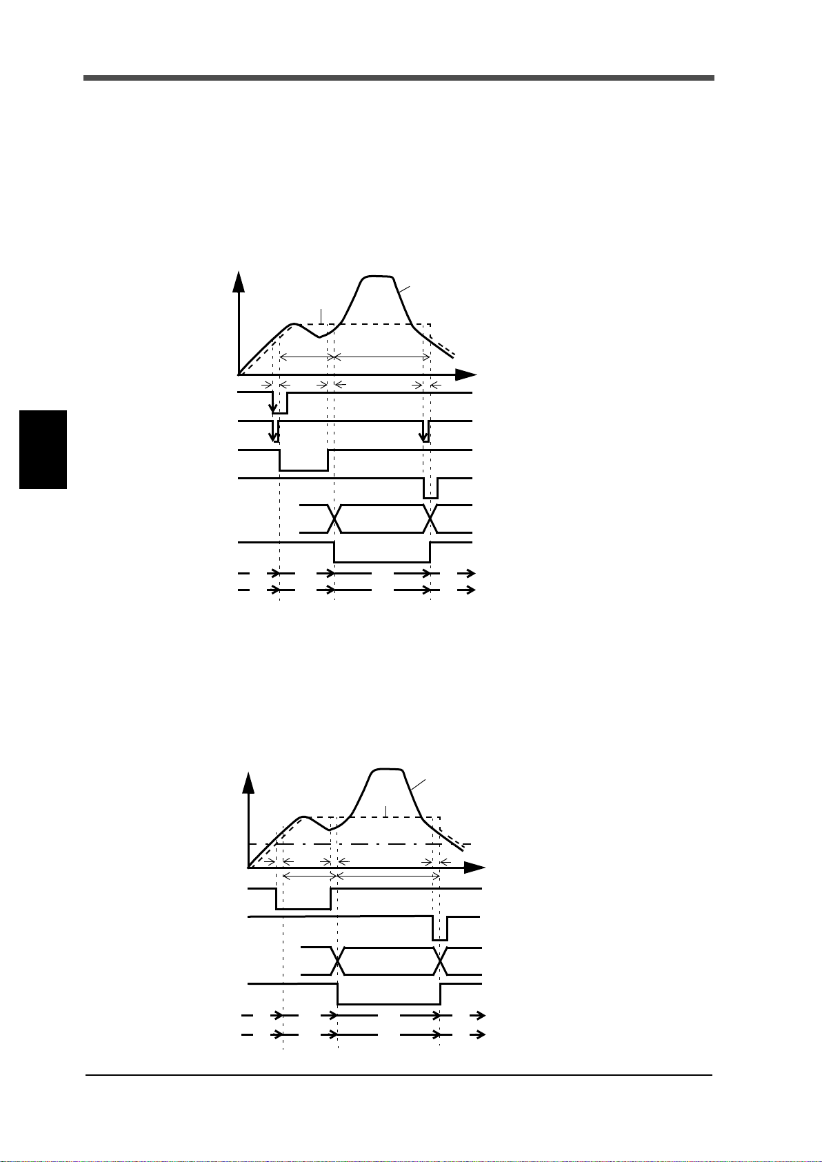
5 SETTING OF FUNCTIONS
Indicated Value
t3
Sensor Input Value
Detection
t
+
H/E
Hold Section
t2
t1
Fixed
SECTION
T/H
OFF
ON
OFF
ON
OFF
ON
OFF
ON
OFF
ON
OFF
ON
ON
Blink ON
OFF ON
OFF
OFF
OFF
HOLD
Button
Detection
HOLD
Status Display
PEAK*
Status Display
Time
HI-LO Limit
Judging Output
*The status display changes depending on the hold mode.
Indicated
t3
Sensor Input Value
Detection
t
+
H/E
Hold Section
t2t1
Fixed
T/H
OFF
ON
OFF
ON
OFF
ON
OFF
ON
ON
Blink ON
OFF ON
OFF
OFF
OFF
HOLD
Status Display
PEAK*
Status Display
Hold Start Level
HI-LO Limit
Judging Output
Val ue
Detection
Time
*The status display changes depending on the hold mode.
External signal + time
Chapter
5
SETTING OF FUNCTIONS
Hold is detected during the predetermined time (hold section time) from the point in time when the
SECTION signal is turned on. The hold is released by turning on the T/H signal as a reset signal.
The next detection is started when the SECTION signal is turned on again even if the T/H signal is
not turned on.
The H/E output signal is on between the instant when the SECTION signal is turned off and the
instant when the T/H signal is turned on.
(Example) External + Time specified section peak hold
t1: A delay time between the instant
when the SECTION signal is inputted
and the instant when the value to be
held is detected
1.0ms (max.)
t2: A delay time between the instant
when the hold section time is expired
and the instant when the value to be
held is determined
1.0ms (max.)
t3: A minimum reset signal width
required for releasing the hold
1.0ms (min.)
Level + time
58
58
Hold is detected during the predetermined time (hold section time) from the point in time when the
indicated value crosses the hold start level. The hold is released by turning on the T/H signal as a
reset signal.
The H/E output signal is on between the instant when the hold section time ends and the instant
when the T/H signal is turned on.
(Example) Level + Time specified section peak hold
t1: A delay time between the instant
when the indicated value exceeds the
hold start level and the instant when the
value to be held is detected
0.5ms (max.)
t2: A delay time between the instant
when the hold section time is expired
and the instant when the value to be
held is determined
1.0ms (max.)
t3: A minimum reset signal width
required for releasing the hold
1.0ms (min.)

5 SETTING OF FUNCTIONS
Indicated Value
t3
Sensor Input Value
Detection
t
+
T/H
H/E
Hold Section
Fixed
OFF
ON
OFF
ON
OFF
ON
ON
Blink ON
OFF ON
OFF
OFF
OFF
HOLD
Status Display
PEAK*
Stat us Dis pl ay
passed HI
passed LO
Hold Start Level
Hold Stop Level
HI-LO Limit
Judging Output
*The status display changes depending on the hold mode.
Level (only Peak and Valley)
By this method, the hold detection section is from the point in time when the indicated value
crosses the Hold Start Level until it crosses the Hold Stop Level. The hold is released by turning on
the T/H signal as a reset signal. The H/E output signal is on between the instant when the hold
section time ends and the instant when the T/H signal is turned on.
However, there are limitations that the Hold Start Level should be passed HI and the Hold Stop
level be passed LO in peak hold, while the Hold Start Level should be passed LO and the Hold Stop
level be passed HI in valley hold.
(Example) Level specified section peak hold
t3: A minimum reset signal width
required for releasing the hold
1.0ms (min.)
Chapter
5-12.Multi-hold Function
59
By this function, up to 16 types of hold, graph and comparison set values can be stored and selected
with external switching signals of WORK0 - WORK3.
Normally, if there is no entry for WORK0 - WORK3, the set value of WORK00 is selected, but when
WORK0 - WORK3 are in the following conditions, the set value of each
WORK3 WORK2 WORK1 WORK0 Measurement work
00 00 WORK00
00 01 WORK01
00 10 WORK02
00 11 WORK03
01 00 WORK04
01 01 WORK05
01 10 WORK06
(0: open, 1: short)
01 11 WORK07
10 00 WORK08
10 01 WORK09
10 10 WORK10
10 11 WORK11
11 00 WORK12
11 01 WORK13
11 10 WORK14
11 11 WORK15
Measurement work
is selected.
5
SETTING OF FUNCTIONS
59
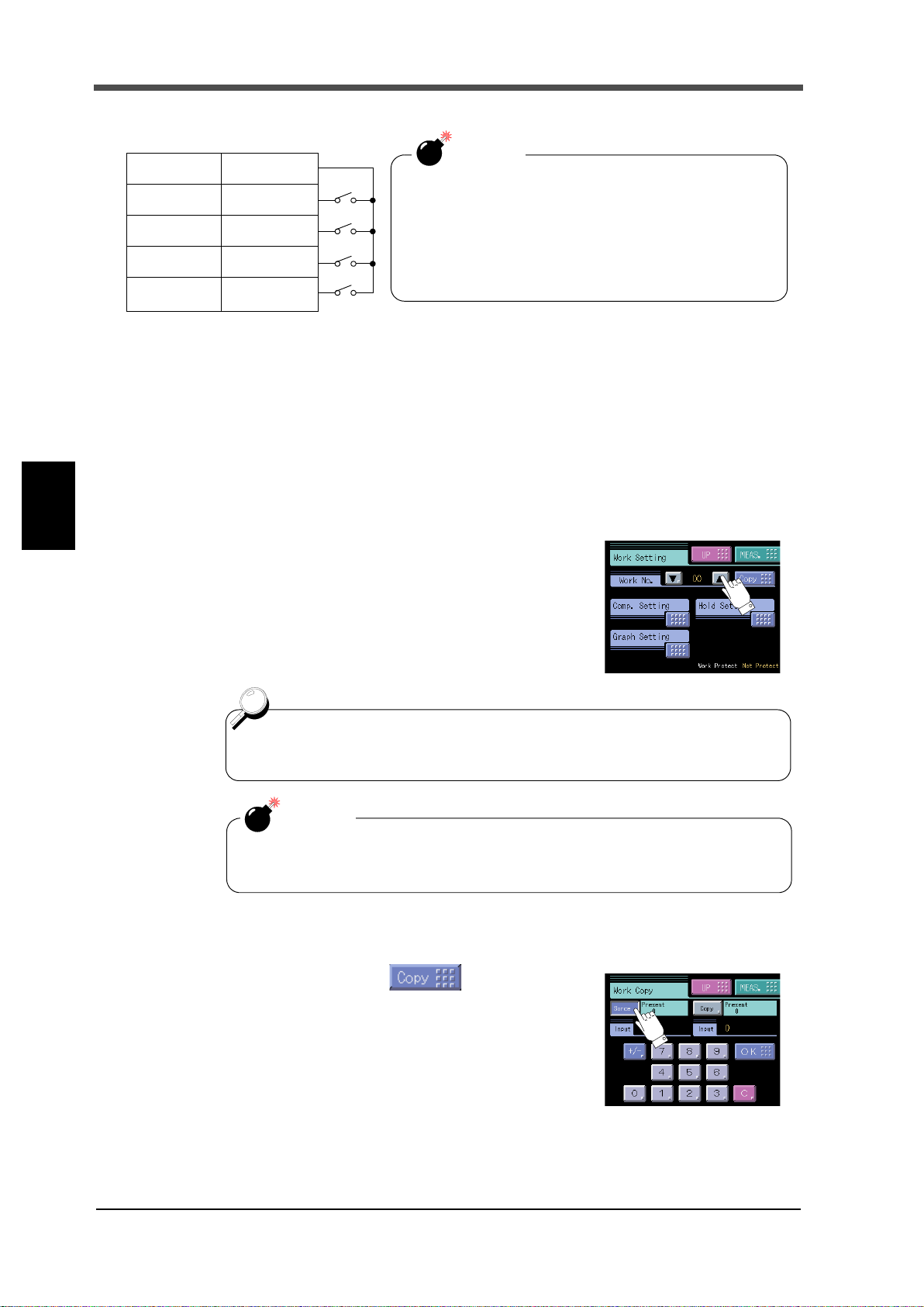
5 SETTING OF FUNCTIONS
I/O terminal block
B1 or
B7 COM2
B2 WORK0
B3 WORK1
B4 WORK2
B5
WORK3
*
CAUTION
It takes 15msec at the maximum for the changed work No.
to become effective. During this section, which work is
measured is undefined.
Also, when the work is switched, the hold and graph
functions are reset under the after-switching work
conditions irrespective of the previous operation.
* If Measurement Work Selection is not set to External Input,
measurement work cannot be specified by external input.
Also, if the B5 Function Selection setting is not WORK3, the B5 pin
does not function as WORK3.
For making the settings of all Works equal, set the Work No. to “All”.
The value set with “All” is set for all WORK00 - WORK15.
CAUTION
The setting work change key is not for specifying the measurement work.
Designate Measurement Work(s) with external selector signals WORK0 - WORK3.
■About changing of the setting work
Chapter
5
SETTING OF FUNCTIONS
When changing the hold or comparison set value of each work, set the Work No. with the Work
change key on the mode selection screen, and change the set value.
How to set
1) Select the setting Work on the Work setting screen.
2) Then, enter each set value in a likewise manner.
■Work copy
Work can be copied. Press on the Work
Setting screen. Set Source(0-15) and Copy(0-15).
Data to be copied are all set values of Comparison
60
60
setting, Hold setting, and Graph setting.
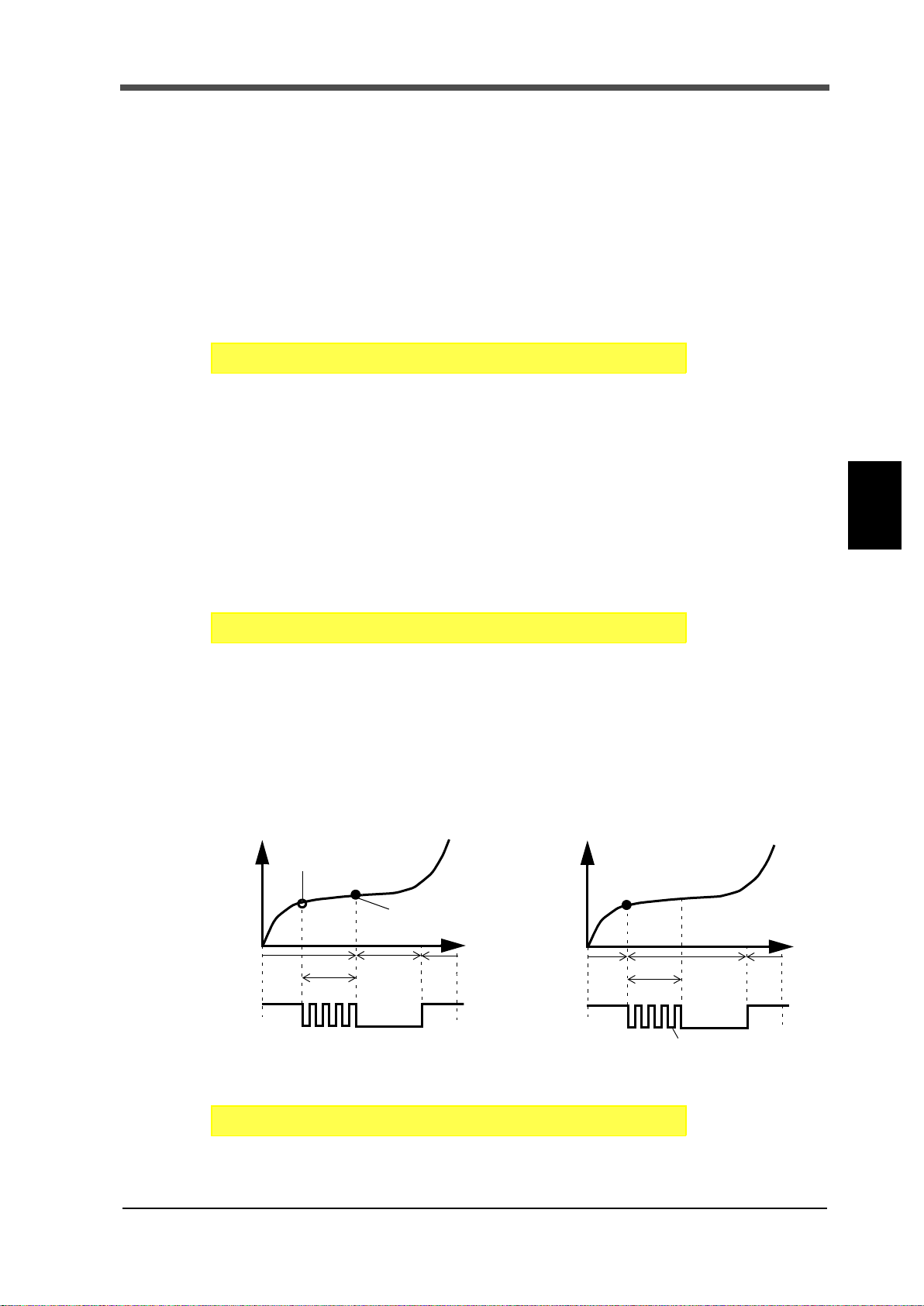
5-13.Measurement Work Selection
SET. Operation Page 3
→→
System Setting
→
SET. Operation Page 3
→→
System Setting
→
Hold point displaced due
Hold point to be taken under normal
Hold section
t
+
T/H
Tracking section Tracking section
Chattering
(80msec)
Hold section
t
+
Tracking section
0.10-sec.
Tracking section
⇒
When the waiting time is 0.00 sec. When the waiting time is 0.10 sec.
ON
OFF
T/H
ON
OFF
circumstances
to chattering
assured section
Chattering operation is ignored
because the input is not recognized.
SET. Operation Page 3
→→
System Setting
→
Select the method for specifying the measurement work.
COM.: Measurement work specification by external input becomes ineffective, and
only measurement work specification by communication (RS-232C, CC-Link
(option) or DeviceNet (option)) becomes effective.
EXT.: Measurement work specification by communication (RS-232C, CC-Link
(option) or DeviceNet (option)) becomes ineffective, and only measurement
work specification by external input becomes effective.
How to set
5-14.Control Input Selection
Select the method for specifying the control (SECTION signal, T/H signal, or GRAPH TRIG
signal) input.
COM.: Control by external input becomes ineffective, and only control by communication
(RS-232C, CC-Link (option) or DeviceNet (option)) becomes effective.
EXT.: Control by communication (RS-232C, CC-Link (option) or DeviceNet (option))
becomes ineffective, and only control by external input becomes effective.
5 SETTING OF FUNCTIONS
Chapter
5
How to set
5-15.B6 OFF Detection Wait
In hold controlled by the TH/signal alone, detection/hold section is assured during the set waiting
time. This is convenient for ignoring chattering parts.
Setting range: 0.00 - 1.00 sec.
Example) Sample hold
SETTING OF FUNCTIONS
How to set
61
61
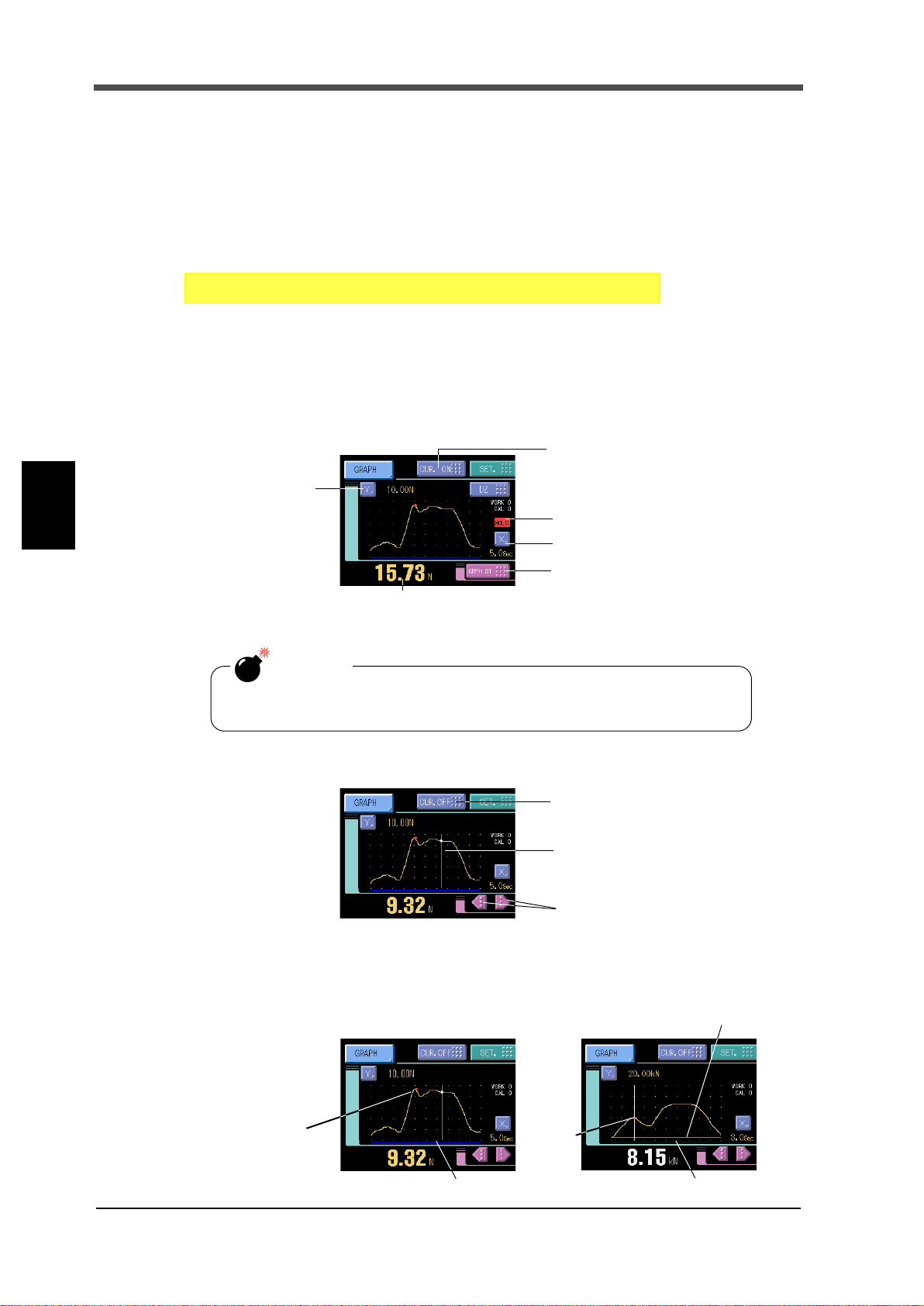
Chapter
SET. Operation Page 3
→→
System Setting
→
X-axis (time axis)
Graphic display START/STOP
Cursor ON/OFF button
Y-axis (load axis)
Indicated value display (At cursor ON time, the cursor
point (red) value is displayed.)
Hold point alarm
status display
CAUTION
When the cursor display is on and when the setting screen is open, the
graph is not upgraded.
Cursor ON/OFF button
The cursor moves to the directlypressed place on the graph.
Cursor move buttons
(The cursor moves on the X-axis.)
Example) Relative maximum hold
Held
point
Held
point
Detection section display
Detection section display
Hold Start Level display
5 SETTING OF FUNCTIONS
5-16.B8 OFF Detection Wait
This is convenient in hold controlled by the SECTION signal.
Operationally, detection/hold section is assured as in the case of B6 OFF Detection Wait.
The timer functions so as to also ignore chattering when the OFF edge is detected.
Setting range: 0.00 - 1.00 sec.
How to set
5-17.Waveform Display
■Graphic display screen
Graph is updated while operating on the ordinary display screen (a comparison, a hold, graph).
5
SETTING OF FUNCTIONS
■Cursor display screen
Hold point plotting
By using the hold function and the graph plotting function together, the held point (red) can be
plotted.
62
62

5 SETTING OF FUNCTIONS
CAUTION
If the hold value is simply renewed without renewing the graph, the value
will differ from the hold point on the graph. In such a case, the hold point
alarm status is displayed.
Plotting Range
D Z
100
Y
X
200
X End Point
Y End Point
Y Start Point
0
t
+
GRAPH TRIG
Start
Plotting Section
(Screen Hold)
Plotting Section
X(TM) end point X(TM) end point
Screen Clear
Interval Time
(
external input
)
OFF
ON
OFF
ON
START/STOP
(Key)
Detection section display
By plotting a graph at the same time as the hold function, a cobalt line indicating the detection
section is displayed at the bottom of the X-axis.
Hold Start Level display
If the Hold Start Level is used in the hold function, a light blue line is displayed. Also, a dotted line
appears when the Hold Start Level is outside the graph area.
X-axis and Y-axis on the graph plotting screen
X-axis The X-axis is a time setting axis. One graph screen is plotted between the start signal
input point and the X start point.
There are 200 plotting points, and typical values for the predetermined time divided by
this number of plotting points are plotted.
Chapter
5
Y-axis The Y-axis is a load setting value. A graph is plotted between the Y start point and the Y
end point. (There are 100 plotting points.)
■Graph plotting
Continued
Graph plotting starts with the GRAPH Start/Stop key input or the GRAPH TRIG external input ON.
When it ends on one screen, the screen is cleared after expiration of the interval time and graph
plotting restarts on the next screen. Plotting ends with the GRAPH Start/Stop key input or the
GRAPH TRIG external input OFF.
SETTING OF FUNCTIONS
63
63

5 SETTING OF FUNCTIONS
t
+
Plotting Section
OFF
ON
OFF
ON
1.0msec more
GRAPH TRIG
(external input)
START/STOP
(Key)
X(TM) end point
Screen Hold, Trigger wait
t
+
Plotting
X(TM) end point
Screen Hold, Trigger wait
Graph Start Level
Section
t
+
Plotting Section
X(TM) end point
Level Detection Section
1.0msec more
Screen Hold, External input wait
Graph Start Level
GRAPH TRIG
(external input)
External
Graph plotting starts with the GRAPH Start/Stop key input or the GRAPH TRIG external input ON.
Plotting ends on one screen at the predetermined time of the X end point.
Chapter
Level
5
SETTING OF FUNCTIONS
External+level
Plotting starts when the Level detection conditions is met in comparison of the Graph Start Level
set value and indicated value. Plotting ends on one screen at the predetermined time of the X end
point.
Example) Graph Start Level→Passed HI
Plotting starts when the Level detection conditions is met in comparison of the Graph Start Level
and indicated value after GRAPH TRIG external input ON.
Plotting ends on one screen at the predetermined time of the X end point.
Example) Graph Start Level→Passed LO
64
64

5 SETTING OF FUNCTIONS
SET. Graph Setting Page 1
→→
Work Setting
→
SET. Graph Setting Page 2
→→
Work Setting
→
SET. Graph Setting Page 1
→→
Work Setting
→
SET. Graph Setting Page 2
→→
Work Setting
→
- Passed
Graph plotting starts when the indicated value crosses the level set value.
- Passed HI
Graph plotting starts when the indicated value crosses the level set value upward.
- Passed LO
Graph plotting starts when the indicated value crosses the level set value
downward.
- Beyond
Graph plotting starts when the indicated value is larger than the level set value.
- Below
Graph plotting starts when the indicated value is smaller than the level set value.
■Graph mode
Set the graph plotting mode.
Setting range: Continued, Ext, Level, Ext+Level
How to set
■Interval time
If you select "Continued" in the graph function setting, set the graph plotting operation interrupting
time from clearing the screen until moving to the next graph plotting operation. During this time,
the graph screen is held.
Setting range: 00.0 - 99.9 sec.
How to set
■Graph start level
If you select [level] or [external + level] in the graph function setting, set the graph plotting start
level.
Chapter
5
Setting range:-99999 - 99999
How to set
■Level detection conditions
If you select [level] or [external + level] in the graph function setting, set the graph plotting start
level comparison conditions.
Setting range: Passed, Passed HI, Passed LO, Beyond, Below
How to set
SETTING OF FUNCTIONS
65
65

5 SETTING OF FUNCTIONS
SET. Graph Setting Page 1
→→
Work Setting
→
Simple setting call
Press the [X] button on the graph display to go direct to the X end point entry screen.
SET. Graph Setting Page 1
→→
Work Setting
→
Simple setting call
Press the [Y] button on the graph display to go direct to the Y end point entry screen.
CAUTION
About the case to switch work and to draw
When beginning to draw, X (Time) end point and Graph mode, etc. are
read. Therefore, please do not do the work switch while drawing when
these settings are different in each work. Please do after drawing ends.
■X(Time) end point
Set the time to display by one screen.
Setting range: 00.1 - 99.9 sec.
How to set
Chapter
■Y(Load) start point and Y(Load) end point
5
SETTING OF FUNCTIONS
Setting range: -99999 - 99999 (where Y start point < Y end point)
How to set
66
66

5-18.Voltage Output
+
-
6
7
-
+
F372A inside
+
-
Analogue
Filter
A/D
+ SIG
- SIG
SW
F.G, shield, etc.
+ MONITOR
- MONITOR
External
equipment
SET. Operation Page 2
→→
System Setting
→
[DSP_LOCK] [KEY_LOCK]
This interface extracts analog voltage proportional to sensor input signals. This interface is
convenient for observation and recording of waveforms with a recorder, etc., connected.
The output level is approx. 2V per 1mV/V of sensor input.
- Example of output equivalent circuit and external equipment connection
Output signals are not the indicated values themselves because they are extracted before sensor
input signals are A/D-converted.
Therefore, output signals do not synchronize with the digitally processed indicated values, such as
the digital zero and digital filter.
Output in synchronization with the indicated values requires an optional D/A converter.
5 SETTING OF FUNCTIONS
Chapter
5
Voltage output filter
5-19.
Whether to extract the voltage output before or after the internal analog filter can be switched.
ON: Output after the analog filter
OFF: Output before the analog filter
How to set
Screen Lock / Key Lock
(B5 terminal function selection)
By the setting of "B5 Function Selection," switching can be done from the WORK3 terminal
function to DSP_LOCK terminal function or KEY_LOCK terminal function.
WORK3: This can be used as the 4th work selection bit of external input.
WORK can be specified from 00 to 15.
DSP_LOCK:
When the terminal is short-circuited, key operations on the measurement
screens (comparison, hold, and graph) are disabled. However, the measurement
screen can be changed (hold to graph) and the cursor function is enabled.
KEY_LOCK: All key operations are disabled.
SETTING OF FUNCTIONS
67
67

Chapter
CAUTION
By the selection of each LOCK function, measurement work that can be
specified externally is limited to WORK00 to WORK07.
SET. Operation Page 2
→→
System Setting
→
Event output
OFF
ON
200msec
The end of graph plotting
*If the time to start the next graph plotting is less than 200msec, the pulse is
forcedly turned OFF when the plotting starts.
Refer to "Error Display List"
on page 88 about the contents
of errors.
RUN
OFF
ON
250msec pulse
This signal turns off when an error occurs.
duty50%
RUN
OFF
ON
3.0sec
Error factor removal
By the error factor removal, ON-OFF
operation restarts in 3.0sec.
5 SETTING OF FUNCTIONS
How to set
5-20.Event Output at the End of Graph Plotting
Each time a graph is plotted on screen, a pulse signal is output (the pulse width is 200msec). The
waveform can automatically be taken in through the RS-232C interface by connecting to the event
input of the DS400.
5
SETTING OF FUNCTIONS
5-21.RUN Output
External output “RUN” stops when abnormal state of indicated value is detected.
The conditions of stopping the output caused by abnormal state are as follows.
・Sensor ±error
・±Over (Overflow error)
・Overload (Overload error)
・Zero error (Zero calibration error)
・Span error (Span calibration error)
・Zero limit (Digital zero limit error)
RUN out specifications are as follows.
RUN output spec
Normally, the signal repeating ON-OFF operation is output.
68
68

5-22.RS-232C Interface
The RS-232C is an interface to read the indicated value and status of the F372A and to write
parameters into the F372A.
This interface is convenient to process controls, totals, records, etc., by connecting the F372A to a
computer, process controller, sequencer or the like.
5 SETTING OF FUNCTIONS
Chapter
■Communication specifications
Specifications
Signal level: Based on RS-232C
Transmitting distance: Approx.15m
Transmitting method: Asynchronous,Full duplex
Transmitting speed: 9600, 19200, 38400, or 57600 bps Selectable
Bit configuration: Start bit 1
Data bit 7 or 8 bit Selectable
Stop bit 1 or 2 bit Selectable
Parity Parity none,odd or even Selectable
Delimiter for sending CR, CR+LF Selectable
Code: ASCII
Connector pin assignment
This connector connects the RS-232C.
(→"RS-232C interface connection" on page 26)
5
SETTING OF FUNCTIONS
69
Cable
(→"RS-232C interface connection" on page 26)
Communication check
The communication can be checked. (→"⑥COM check" on page 91)
69

Chapter
SET. RS-232C Setting Page 1
→→
System Setting
→
SET. RS-232C Setting Page 1
→→
System Setting
→
SET. RS-232C Setting Page 1
→→
System Setting
→
SET. RS-232C Setting Page 1
→→
System Setting
→
SET. RS-232C Setting Page 1
→→
System Setting
→
SET. RS-232C Setting Page 2
→→
System Setting
→
SET. RS-232C Setting Page 2
→→
System Setting
→
5 SETTING OF FUNCTIONS
■RS-232C interface setting
Set the RS-232C communication conditions of the F372A.
Communication mode
Normal, Continue, Print
How to set
Baudrate
9600, 19200, 38400, 57600bps
How to set
Data bit
7bit, 8bit
How to set
5
SETTING OF FUNCTIONS
Stop bit
1bit, 2bit
How to set
Parity bit
NONE, ODD, EVEN
How to set
Delimiter
CR, CR+LF
How to set
Flow control
Off, RTS/CTS
How to set
■Communication mode
1.Normal
Communications are carried out by commands from the host computer.
The indicated value, status and parameters can be read, and parameters can be written.
2.Continue
The indicated value and status are continuously transmitted.
3.Print
The indicated value is transmitted upon printing (when a print command is output to the SI/F).
70
70

■Communication format
Host
F372A
RA CR
RA
Delimiter
+
1 0 0 0 0 .
* If the indicated value has no decimal point, a decimal point follows the numerical value.
Host
F372A
RD CR
R D 0 0 0 0 0 0 0
1:ON
0:OFF
1:ON
0:OFF
Near Zero 1:ON
Output signal 0:OFF
HI 1:ON
Output signal 0:OFF
LO 1:ON
Output signal 0:OFF
OK 1:ON
Output signal 0:OFF
Undefined
*Hold
Stable
Delimiter
Host
F372A
RC CR
R C 0 0 0 0 0 0 0
1:ON
0:OFF
1:ON
0:OFF
1:ON
0:OFF
1:ON
0:OFF
LL 1:ON
Output signal 0:OFF
HH 1:ON
Output signal 0:OFF
Overload
Sensor +error
Delimiter
Output signal 0:OFF
1:ON
Sensor -error
+OVER
-OVER
1.Normal
- Reading the indicated value (sign, 5-digit indicated value, decimal point)
- Reading the status (7-digit)
5 SETTING OF FUNCTIONS
Chapter
*The hold bit is operated at the same timing as the H/E signal.
5
SETTING OF FUNCTIONS
71
71

5 SETTING OF FUNCTIONS
1W2
CR3 1
W
CR41
W
CR
CR05 1
W
CR8 4
W
CR6 1
W
0
(Calibration Protect)
0
1W1CR
Work Setting
±
±
±
±
±
CR44W
(Calibration Protect)
00000
⑥
Protect
(
(
Work Setting
Protect
(
(
Work Setting
Protect
(
(
Work Setting
Protect
(
(
Work Setting
Protect
(
(
Work Setting
Protect
(
(
CR52
W
00 0 00
③
CR32
W
±
CR1 2
W
0 0 0 0
CR2 2
W
0 0
CR42
W
0
CR62
W
0
CR72
W
0
00
CR17
W
0
0 0 0
0
0
①
②
Work Setting
Protect
(
(
Work Setting
Protect
(
(
Work Setting
Protect
(
(
Work Setting
Protect
(
(
Work Setting
Protect
(
(
Work Setting
Protect
(
(
Work Setting
Protect
(
(
Work Setting
Protect
(
(
CR82
W
0
00
3 W1 CR
0 0000
3 W2 CR
0 00
④
CR 043
W
00 00
CR3 3 W ±
CR 0F1
W
00 0
⑤
CR92
W
0
0±
Work Setting
Protect
(
(
Work Setting
Protect
(
(
Work Setting
Protect
(
(
Work Setting
Protect
(
(
Work Setting
Protect
(
(
Work Setting
Protect
(
(
* When writing work setting values, specify the work by this setting
in advance.
- Writing parameters
HH Limit
HI Limit
LO Limit
LL Limit
Hysteresis
Cal. Select
Digital Offset
Near Zero
Chapter
5
SETTING OF FUNCTIONS
Hold Mode
Hold Section
Section Time
Hold Start Level
Rel.Minimum Count
Rel.magnification
Inf.Minimum Slope
Inf.F Slope Time
Inf.R Slope Time
Graph Mode
Interval Time
Graph Start Level
Level detection conditions
Work No .
Samp.Removal Val.
72
72
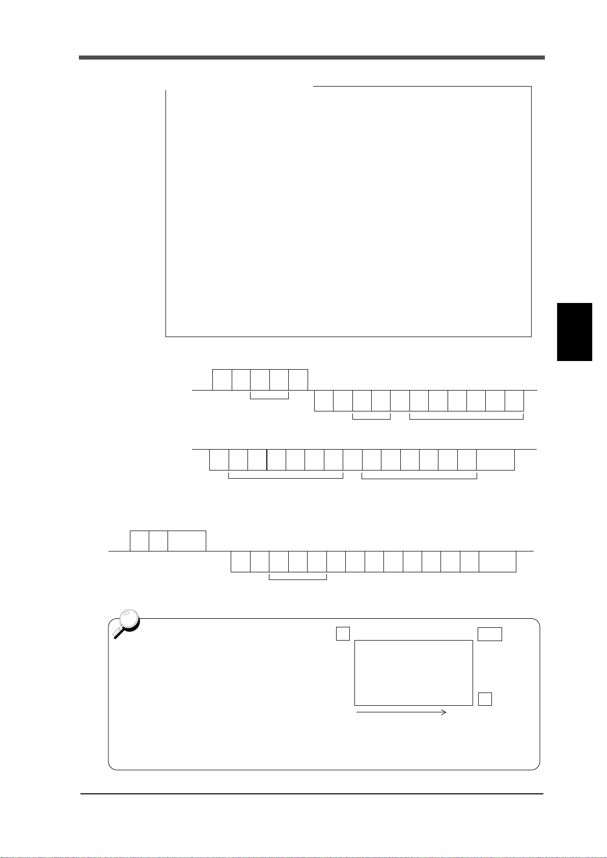
5 SETTING OF FUNCTIONS
① Hold Mode ② Hold Section ③ Rel.magnification
0: OFF 0: All 0: ×0.25
1: Sample 1: EXT 1: ×0.50
2: Peak 2: EXT+TM 2: ×0.75
3: Valley 3: LVL+TM 3: ×1.00
4: P-P 4: LVL 4: ×1.25
5: Average 5: ×1.50
6: Inf. Pnt 6: ×2.00
7: Rel. Max 7: ×3.00
8: Rel. Min 8: ×4.00
9: Rel. Dif
④ Graph Mode ⑤ Level detection conditions ⑥ Calibration Selection
0: Continued 0: Passed 0: Cal.0
1: Ext 1: Passed HI 1: Cal.1
2: Level 2: Passed LO 2: Cal.2
3: Ext+Level 3: Beyond 3: Cal.3
4: Below 4: EXT.
Set value correspondence table
Host
F372A
G
R
CR
Decimal Point and Five digits Data1
00 - 19
R
Data Section No.
G
±
00 - 19
Data Section No.
……
Delimiter
±±
……
Decimal Point and Five digits Data9 Decimal Point and Five digits Data10
Host
H
R
R
H
……
CR
Delimiter
+ 10 0 00.025 ,
DATA000 - 199
F372A
One graph plotting screen
includes 200 pieces of data. In
reading waveform data, data can
be read by being divided into 20
sections (by 10 pieces).
Data Section No.
Y
DZ
X
Plotting Range
Data 0
Data 199
Section 00 Data 0 - Data 9
Section 01
Data10 - Data 19
Section 19
Data190 - Data 199
~
Chapter
- Reading waveform data
-
Wave form hold point data read-out
(data No, a mark, a decimal point,5 figures of directions value)
73
5
SETTING OF FUNCTIONS
73
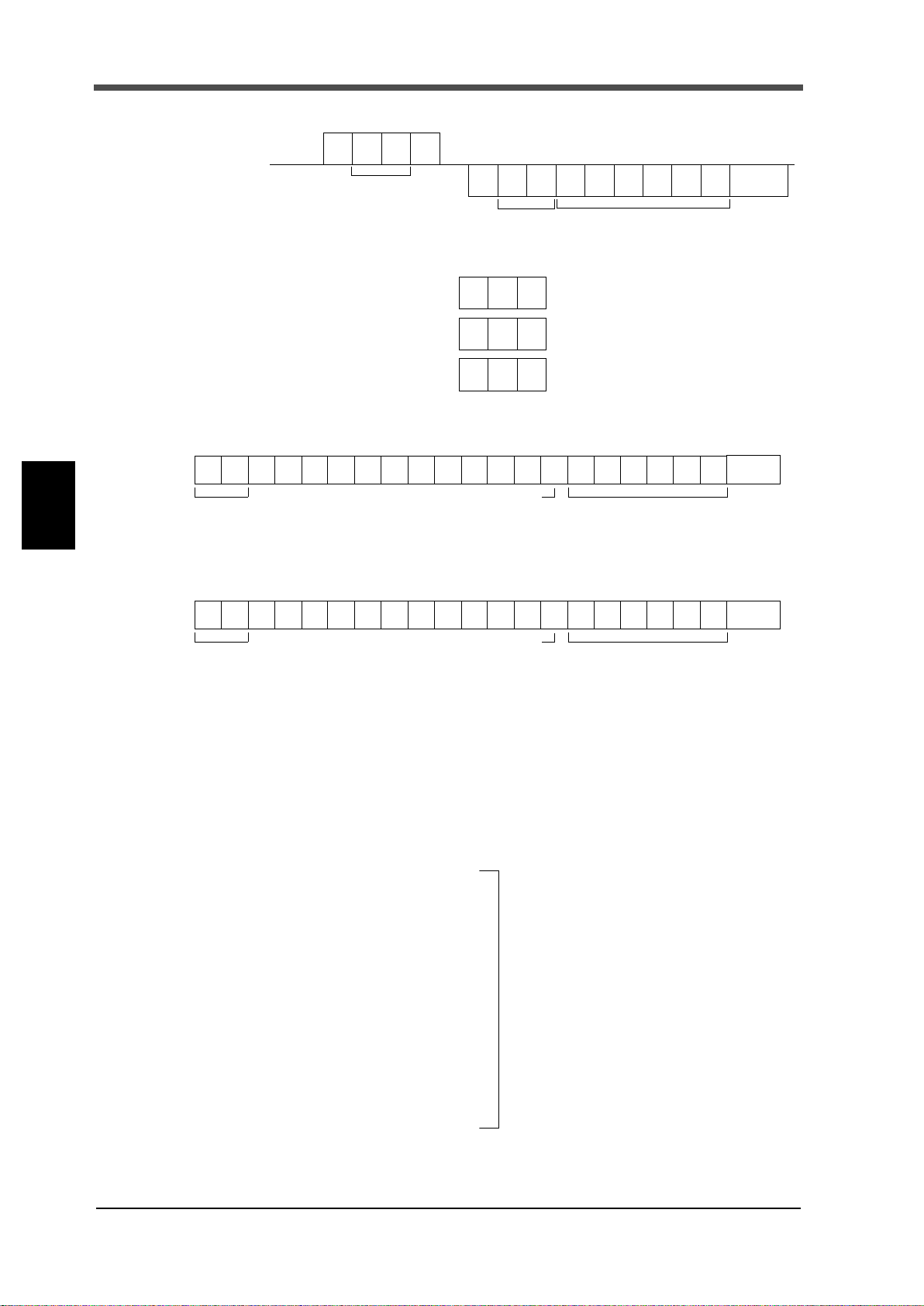
5 SETTING OF FUNCTIONS
Host
F372A
W
W
CR
Set Value No. The same format as write-in
of set values.
Set Value No.
Delimiter
CR
CR
CR
C
C
C
G
H
I
(This will issue print a command onto SIF.)
0 1 2 3 4 5 6 7 8 9 10 11 12 13 14 15 16 17 18 19 20 21
G S , 1 , 2 , 3 , 4 , 5 , ±
****
HEADER
Five digits of the indicated value
Sign
+ or -
*
Delimiter
and decimal point
0 1 2 3 4 5 6 7 8 9 10 11 12 13 14 15 16 17 18 19 20 21
G S , 1 , 2 , 3 , 4 , 5 , ±
****
HEADER
Sign
+ or -
*
Delimiter
Five digits of the indicated value
and decimal point
Even if the HI-LO limit output selection is changed
to other than H2/L2, characters will not change.
- Reading parameters
- Commands (Host→F372A)
Chapter
5
SETTING OF FUNCTIONS
Digital Zero
Digital Zero reset
Print instruction
2.Continue
The indicated value is continuously transmitted.
3.Print
The indicated value is transmitted upon printing.
*1
O ........ Sensor ±error,±OVER
........ Stable
S
M....... Not Stable
H ....... Hold
*1 Priority H>O> (S or M)
*2
A ....... Zero Tracking OFF
T........ Zero Tracking ON
*3
H ........ HI limit ON
L......... LO limit ON
G ........ HI limit and LO limit OFF
N ........ HI limit and LO limit ON
........ Compare OFF
F
*3
Priority N> (H or L) F> G
*4
H ........ HH limit ON
L......... LL limit ON
G ........ HH limit and LL limit OFF
N ........ HH limit and LL limit ON
........ Compare OFF
F
*4
Priority N> (H or L) F> G
74
74
*5
N ....... Near Zero OFF
........ Near Zero ON
Z

6-1. BCD Data Output (Option)
6 OPTION
B16
A16
A1
B1
BCD output connector
The BCD data output is an interface to extract the indicated value of the F372A as BCD data. This
interface is convenient to process controls, totals, records, etc., by connecting the F372A to a
computer, process controller, sequencer or the like.
The I/O and internal circuits are electrically insulated by photocoupler.
6 OPTION
■Connector pin assignment
32 pin
No. Signal No. Signal
A1
*
A2 OUT 1 B2 OUT 1000
A3 OUT 2 B3 OUT 2000
A4 OUT 4 B4 OUT 4000
A5 OUT 8 B5 OUT 8000
A6 OUT 10 B6 OUT 10000
A7 OUT 20 B7 OUT 20000
A8 OUT 40 B8 OUT 40000
A9 OUT 80 B9 OUT 80000
A10 OUT 100 B10 OUT Minus (Polarity)
A11 OUT 200 B11 OUT OVER
A12 OUT 400 B12 OUT STAB
A13 OUT 800 B13 OUT STROBE
A14 IN BCD Data Hold B14 IN Logic Switching
A15 IN Output Data Switching B15 IN
A16
Compatible connector: FCN-361J032-AU (manufactured by FUJITSU COMPONENT or equivalent)
Connector cover: FCN-360C032-B (manufactured by FUJITSU COMPONENT or equivalent)
(Connector & Cover optional type: CN51)
-
COM B1
B16
Chapter
6
*
-
COM
OPTION
75
75
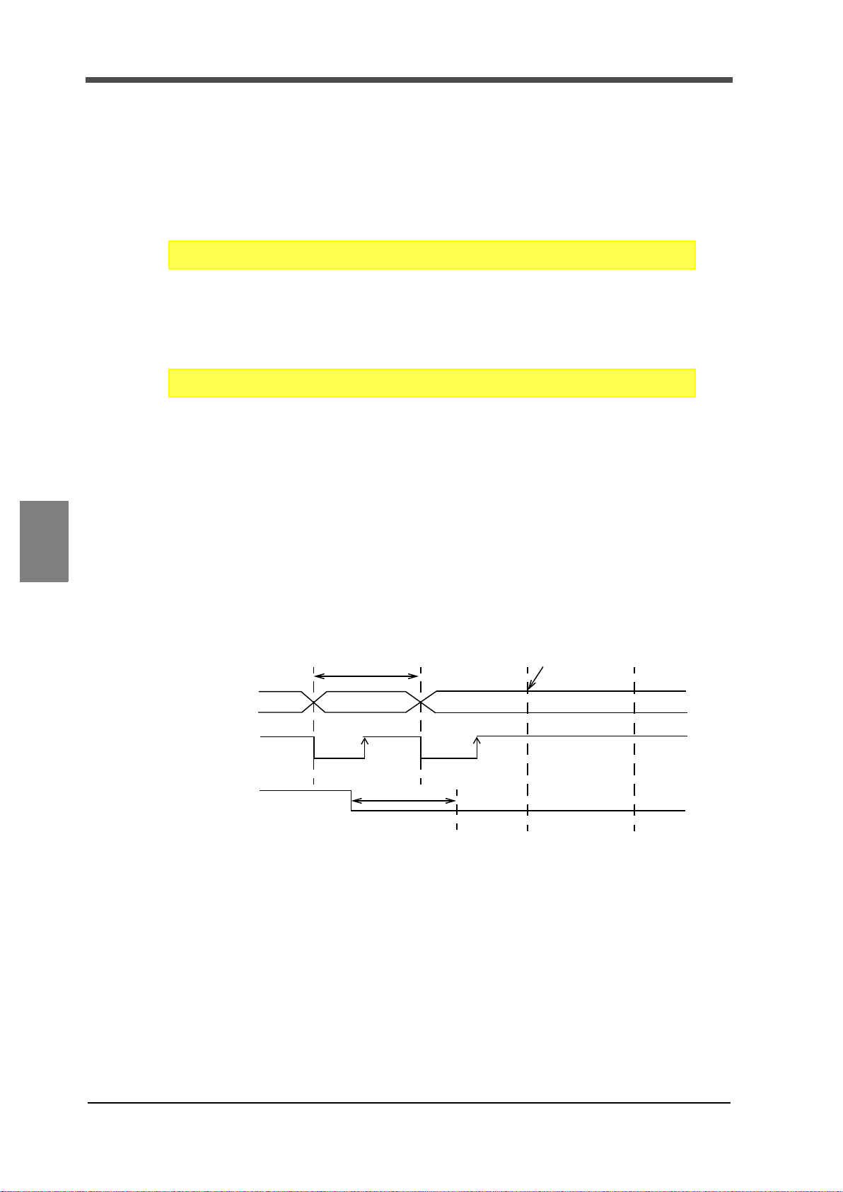
Chapter
SET. Option Setting (BCD OUT) Page 1
→→
System Setting
→
SET. Option Setting (BCD OUT) Page 1
→→
System Setting
→
BCDdata
OFF
ON
BCD data
1 cycle
1 cycle (max)
Renewal is stopped.
0
1
STROBE
hold
6 OPTION
■BCD output select
When "External" is set by the BCD Output Select setting, the output data is switched by A15. In
the case of external selection, read after at least 2 cycles.
When COM and A15 are open: real time value, When they are short-circuited:hold value
Output data: Realtime, Hold, EXT.
How to set
■BCD output rate
Output rate: 10, 20, 50, 100, 200, 500, 1000, 2000〔Times/sec.〕
How to set
■Logic switching
Select the logic of output signals with pin B14.
Read at least 2 cycles after inputting the logic switching.
When COM and pin B14 are open: negative logic, When they are short-circuited: positive logic
6
OPTION
■BCD data hold
Renewal of the BCD data output signal is stopped. Also the STROBE output is turned OFF.
Switching is done by A14. When COM and A14 are open: hold cancel, When they are short-
circuited: hold on
Read at least 2 cycles after inputting the BCD data hold.
As long as the BCD Data Hold signal is inputted, data can be read reliably, but because the data is
not renewed, it may be different from proper data.
76
76
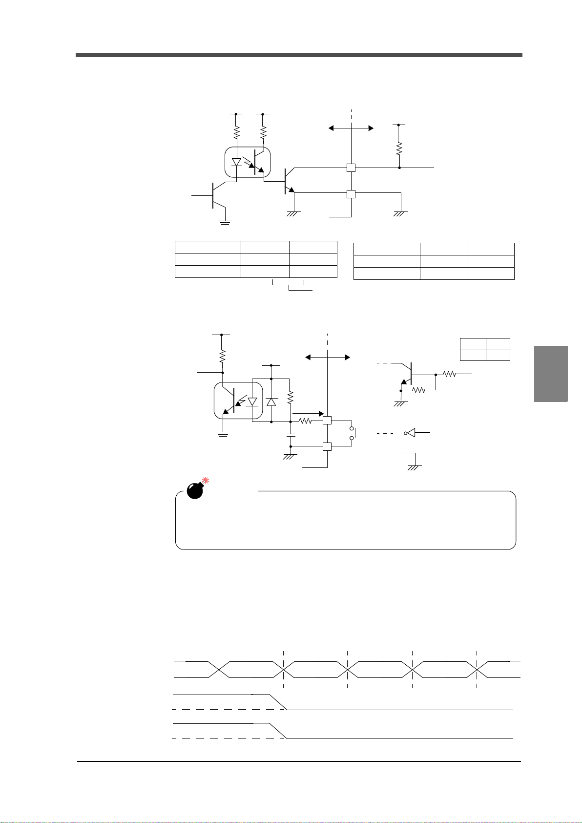
■Equivalent circuit
F372A
Inside
Vcc
+5V
COM
Vex t
Vceo=30V(max)
Ic =30mA (max)
Output data Negative Positive
0OFFON
1ONOFF
Output data Negative Positive
0
HL
1
LH
Through logic switching (B14)
Outside
Internal transistor status Output pin level
Vcc
F372A
Inside
IC=
Approx.
COM
Switch
Transistor
+5V
TTL open collector output
Open OFF
Short ON
Outside
6mA
(ON when IN is HI)
CAUTION
-
Do not apply external voltage to the signal input circuit.
- The external element is required to withstand Ic=10mA.
- Leakage from the external element is required to be 30μA or below.
BCDdata
STAB
OVER
0
1
0
1
-Output The signal output circuit is operated through a TTL open collector.
-Input
6 OPTION
■Signal timing
-STAB This signal turns on at the same time as BCD data when stability is detected by Motion
-OVER This signal is output at the time of a sensor error or ±OVER.
Detect (MD). This signal is not output when the output data is a real time
value.("Motion Detect (MD)"on page 41)
Chapter
6
OPTION
77
77
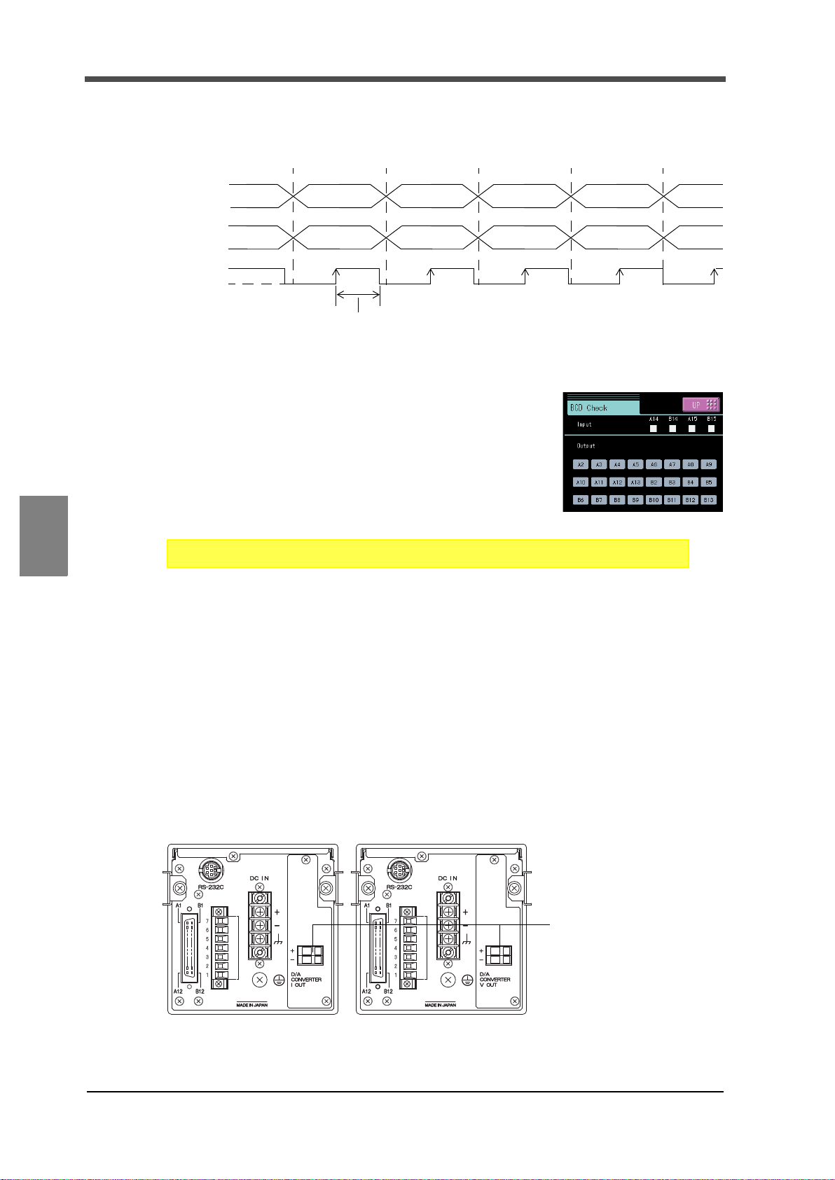
6 OPTION
BCDdata
OVER
STROBE
Strobe range
0
1
(duty50%)
SET. Option Setting (BCD OUT) Page 1
→→
System Setting
→
Voltage / current output terminals:
terminals to extract voltage or
current signals.
-10 to +10V and 4 to 20mA can
be obtained by the voltage output
and current output, respectively.
-STROBE Strobe pulses are output in synchronization with BCD data. Read data using the rising
edges of the pulses. The BCD data output rate setting can be changed.
Example) Negative logic
■Self check
The BCD input / output status can be checked from bit to bit.
Each input turns green when its ON state is recognized.
Each output turns on when the corresponding button is pressed.
Chapter
6
OPTION
How to set
6-2. D/A Converter (Option)
A D/A converter is provided for obtaining analog output synchronized with the indicated value of
the F372A.
The analog output ranges are -10 - +10V output and 4 - 20mA constant-current output.
By using the D/A zero setting and D/A full scale setting functions, analog output can be obtained
between zero (0V, 4mA) and full scale (10V, 20mA) with respect to the predetermined digital value.
The output circuit and the main unit circuit are isolated. The resolution is 1/10000 to -10 - +10V
and 4 - 20mA, and the conversion rate is 2000 times/sec. The maximum voltage output range are
about ±11V, the maximum current output range are about 2.4 - 21.6 mA.
78
78

- Taking voltage output signals
+
-
+
-
F.G, shield, etc.
← Inside Outside →
F372A
External equipment
Load resistance:
2kΩ or more
+
-
F.G, shield, etc.
F372A
+
-
← Inside Outside →
External equipment
Load resistance:
350Ω or less
CAUTION
- The D/A converter is optional.
- Do not apply external voltage because it will break.
- Do not short-circuit the voltage output because a failure will occur.
Also, connecting a capacitive load may cause oscillation.
SET. Option Setting (D/A OUTPUT) Page 1
→→
System Setting
→
Connect external equipment (2kΩ or more
load resistance) to + and - of the F372A.
- Taking current output signals
Connect external equipment (350Ω or less
load resistance) to CUR and G of the
F372A.
6 OPTION
- Resolution
The D/A converter has a resolution of 1/10000 to -10 - +10V (4 - 20mA).
■Scale setting value selection
Four types of zero scale and full scale settings can be stored.
Switch with the selector button ( / ) to conduct scale setting.
Scale of output of D/A converter changes accordingly when gain changes by the selection of
calibration value.
How to set
■Zero scale output value and full scale output value
Chapter
6
OPTION
Setting range: -99999 - 99999 (where zero set value < full scale set value)
- In the case of voltage output
Zero scale: Set the indicated value for the time of output of 0V.
Full scale: Set the indicated value for the time of output of 10V.
- In the case of current output
Zero scale: Set the indicated value for the time of output of 4mA.
Full scale: Set the indicated value for the time of output of 20mA.
79
79

6 OPTION
SET. Option Setting (D/A OUTPUT) Page 1
→→
System Setting
→
SET. Option Setting (D/A OUTPUT) Page 1
→→
System Setting
→
Clear button
Simulated trimmer
UP・DOWN button
Simulated trimmer position
display
(The trimmer moves to the
directly-pressed place.)
adjustment
How to set
■D/A output select
Hold, Realtime, Zero scale, Full scale
How to set
How to output adjust
Select each fixed output in D/A output select, and press the button, and then use the
Hold : Output is produced in synchronization with the indicated value.
Realtime : Output is produced in synchronization with the sensor input value.
Zero scale : Output is fixed at zero output (0V or 4mA).
Full scale : Output is fixed at full scale (10V or 20mA).
Chapter
6
OPTION
simulated trimmer appearing on the adjustment screen to adjust the output.
While monitoring the output value, make fine adjustment of the output with the UP/DOWN
button of the simulated trimmer, and determine by pressing the button, so
that the trimmer position is entered.
* Pressing the simulated trimmer buttons continuously performs continuous
operation.
* The trimmer adjusting ranges are as follows: voltage output; about ±2.0V, and current
output; about ±1.6mA.
* The [Clear] button resets the Simulated trimmer position to the trimmer center point (0%).
80
80

6-3. External I/O (Source type (ISC) option)
Vceo=30V(max)
COM1
Output
Ic=30mA(max)
Input
COM
F372A
Source type
PLC, etc.
Minus common connection
A1,A7
A2 ~ A6
A8 ~ A10
DC24V
COM
Output
Ic= app.5mA
Input
COM2
PLC, etc.
Source type
F372A
Minus common connection
B1,B7
B2 ~ B6
B8 ~ B12
DC24V
CAUTION
・Connect elements that can pass Ic=5mA or more.
・The leak current of the elements connected should be 400μA or less.
・External power supply (DC24V) is needed since F372A does not have
the power supply
The source type external input/output signal is an option which can be changed external input/
output signal of F372A to source type. (The standard is sink type.)
The connection of external input/output signal is the minus common.
How to connect external output(Source type)
- Equivalent circuit
6 OPTION
How to connect external input
(minus common connection of voltage input type)
- Equivalent circuit
81
Chapter
6
OPTION
81

7 SPECIFICATIONS
7 SPECIFICATIONS
*Section setting (“all section”,
“external signal”, “external
signal+time”, or “level+time”) is
available for 2) - 5).
*Section setting (“level”) is
available for 2) - 3).
7-1. Specifications
■Analog section
Sensor excitation 10V, 2.5V DC
Output current: Within 120mA
4-wire (Up to four 350Ωload cells can be connected.)
Signal input range -3.0 - +3.0mV/V
Zero and gain adjustment Performed by digital computation
Accuracy Non-linearity: Within 0.02%FS±1 digit (at a 3.0mV/V input)
Zero drift: Within 0.5μV/℃RTI
Gain drift: Within 0.01%/℃
A/D converter Rate: 2000 times/sec.
Rate: 24 bits (binary)
Effective resolution: Approx. 1/30000 to 3.0mV/V input
Analog filter 30Hz, 100Hz, 300Hz, 1000Hz
Voltage output Output level: Approx. 2V per 1mV/V of input Load
Chapter
■Digital section
Display 3.5 inch TFT color LCD module (display area: 71mm×53mm)
7
SPECIFICATIONS
82
82
Equivalent input calibration
Hold functions 1) Sample hold
Comparison functions External output
Calibration value selection
Load resistance: 2kΩ or more
320×240 dots
Indicated value: ±99999 (5-digit)
Range: 0.5 - 3.0mV/V Error: Within ±0.1%FS
2) Peak hold
3) Valley hold
4) P-P hold
5) Average hold
6) Inf. Pnt hold
7) Rel. Max hold
8) Rel. Min hold
9) Rel. Dif hold
HH limit HH
LL limit LL
OK
HI limit HI
LO limit LO
Four calibration values can be stored in memory and switched.

■Standard interfaces
RS-232C communication interface
Start/stop system
Baud rate: 9600bps - 57600bps
SI/F (2-wire serial interface)
Start/stop system
Baud rate: 600bps
■Options interfaces
BCD data output Open collector
Output rate
Can be selected from 10, 20, 50, 100, 200, 500, 1000 and 2000 times/sec.
Capacity 30V, 30mA
D/A converter Voltage output (DAV) -10 - +10V RL>2kΩ
Current output (DAI) 4 - 20mA RL<350Ω
Zero output and full scale output can be digitally adjusted.
Zero adjusting range: ±10%FS
Gain adjusting range: ±10%FS
Zero drift: Within 0.6mV/℃ (DAV)
Within 0.5μA/℃ (DAI)
Gain drift: Within 50ppm/℃
Non-linearity: 0.05%FS
Response: Dependent on the A/D conversion speed
(2000 times/sec.) of the main unit
7 SPECIFICATIONS
■External input and output
Output
HI-LO limit comparison output - HH, HI, OK, LO, LL
Normal operation output - RUN
Hold end output - H/E
Graph plotting end output - EVENT
Input
Work selection input - WORK0, WORK1, WORK2, WORK3
Hold control input - T/H, SECTION
Digital zero input - DZ
Graph plotting control input - GRAPH TRIG
Calibration Selection input - CAL0, CAL1
■General
Power source - DC spec DC24V (±15%)
Power consumption - DC spec 18W max
Rush current (Typ) 55A, 1msec (ordinary temperature, at cold-start time)
Operating conditions Operation temperature: 0℃ to +40℃
Storage temperature: -20℃ to +60℃
Humidity: 85%RH or below (non-condensing)
Warmup time 20 minutes
Chapter
7
SPECIFICATIONS
83
83

7 SPECIFICATIONS
+1
-0
[Unit:mm]
Dimensions 96.0W×96.0H×138.0D [mm] (excluding projected parts)
Panel cutout size 92×92 mm(Board thickness:1.6~3.2㎜)
Weight Approx. 1.0kg
■Accessories
Operation manual ..................................................................................................................... 1
Control signal Input/Output connector ..................................................................................... 1
Connector for BCD output (with BCD option) ........................................................................ 1
Mini screwdriver (with DAV/DAI option) ............................................................................... 1
Connector for CC-Link (with CC-Link option) ....................................................................... 1
Connector for DeviceNet (with DeviceNet option).................................................................. 1
7-2. Dimensions
■Standard
Chapter
7
SPECIFICATIONS
84
84

7 SPECIFICATIONS
[Unit:mm]
[Unit:mm]
■Equipped with BCD parallel data output interface option
■Equipped with CC-Link interface option
Chapter
7
SPECIFICATIONS
85
85

7 SPECIFICATIONS
[Unit:mm]
■Equipped with DeviceNet interface option
Chapter
7
SPECIFICATIONS
86
86

7-3. F372A Block Diagram
+
EXC
-
EXC
+
SIG
-
SIG
Low-pass
Fillter
×100
Excitation
Reference
A/D
SHIELD
FRAME
Gain
Serial
Port
Port
Port
Port
Serial
Port
RAM
16Kbyte
CPU
32bit
Flash
ROM
256Kbyte
Wat c h
Dog
NOV.RAM
4096bit
Input
T/H DZ WORK0~3
SECTION GRAPH TRIG
10 Line
SI/F
DeviceNet
CC-Link
HI HH OK
H/E RUN EVENT
SIF
MPU
Touch
LCD
LCD
D/A
BCD
LO LL
+5VI+12V
I
-9VA +5V
D
Power Supply Unit
+9VA
Option
+MONITOR
Buffer
Serial
Port
RS-232C
Flash
ROM
External
SRAM
(DAVorDAI)
- MONITOR
CAL0 CAL1
Isolation
+
-
DC IN (24V)
adjustment
Voltage
Voltage
Conversion
External
Lithium
battery
Standard
Driver
Analogue Digital
Control
Input
8 Line
Control
Output
Panel
FRAME
7 SPECIFICATIONS
Chapter
7
87
SPECIFICATIONS
87

8 SUPPLEMENTS
8
SUPPLEMENTS
8-1.
Error Display List
When either of the following errors occur, the RUN signal of an external output is turned off.
■Sensor +error or Sensor -error
This message indicates that the inputted electric signal exceeds the input voltage range of the
element (ADC) which converts the inputted electric signal to a digital value whereby the signal
cannot be converted to a correct digital value.
Sensor +error and Sensor -error indicate that the inputted electric signal exceeds the input range in
the positive direction and negative direction, respectively.
This message may also be displayed when an excessive load is applied to the sensor or the input
terminals are opened due to a break in the cable.
■+Over or -Over (Overflow error)
This message indicates that the value to be displayed except the decimal point and sign exceeds five
digits. The message and a value of as much as five digits appear alternately.
+OVER and -OVER indicate that the value to be displayed exceeds five digits in the positive
direction and negative direction, respectively.
This message is displayed in such a case wherein a load larger than expected is applied or
calibration is performed below the measuring range. Check calibration and the measuring object.
■Overload (Overload error)
An Overload error results when the real time value (sensor input value) exceeds the alarm HI limit
or drops below the alarm LO limit.
Check the sensor for excessive load.
Chapter
8
SUPPLEMENTS
■Zero error (Zero calibration error)
This message indicates that calibration cannot be performed because the inputted electric signal
exceeds the input voltage range.
Check the cables for breaks or miswiring.
■Span error (Span calibration error)
The span calibration error occurs under the following conditions.
1) An actual load set value of zero is inputted.
2) An electric signal of -0.005 to 0.005mV/V is inputted.
In the case of 1), check the set value, and perform calibration again.
In the case of 2) , check that the actual load is properly applied and check the cables for
miswiring.If the load is too light, the load needs to be increased.
Although the F372A will not break down immediately even if the above messages are displayed,
Sensor +error or Sensor -error indicates that an excessive voltage may be applied to the input circuit
of the F372A. It is therefore required to remove the cause immediately.
(Although the input is provided with a protection circuit, a long-time excessive voltage or an
instantaneous but extremely high voltage may break the F372A.)
■Zero limit (Digital zero limit error)
A zero limit error results when the range of zero-point correction (deviation from the zero
calibration registered point) by digital zero or zero tracking exceeds the Digital Zero Limit set
value.
Reset the digital zero, or perform digital zero in an appropriate range.
88
88

8-2. Protect / Initialization
SET. Protect / Init. Page 1
→→
SET. Protect / Init. Page 1
→→
SET. Protect / Init. Page 1
→→
SET. Protect / Init. Page 1
→→
SET. Protect / Init. Page 1
→→
■Work setting protect
Set whether to protect the set values in Work Setting from changing.
Setting range: ON / OFF
How to set
■System setting protect
Set whether to protect the set values in System Setting from changing.
Setting range: ON / OFF
How to set
■Calibration protect
→See page34 "Calibration Protect".
8 SUPPLEMENTS
How to set
■Expansion protect
Set whether to protect the set values in Expansion Setting from changing
Setting range: ON / OFF
How to set
■Initialization
All the set values of each setting item are initialized to their factory defaults.
Select the setting item you want to initialize.
Setting range: Work Set. / System Set. / Calibration Set./ Expansion Set.
* If the setting item on which you intend to execute initialization is protected, initialization cannot
be executed.
How to set
Chapter
8
SUPPLEMENTS
89
89

8 SUPPLEMENTS
SET. LCD Check
→
Self Check
→
SET. KEY Check
→
Self Check
→
SET. MEM Check
→
Self Check
→
SET. I/O Check
→
Self Check
→
SET. DSP Check
→
Self Check
→
8-3. Self-Check
■Self-check
The self-check function includes a memory check to check the memory automatically for detecting
problems, a visual check to check the display visually, a touch panel key input check and an
external I/O check.
①LCD check
Check the display to see that it is free from color and display defects, etc. The screen changes from red,
green, blue, horizontal stripes, to vertical stripes. Touching the screen restores the previous screen.
How to set
②KEY check
Check the touch panel to see that it is free from unrecognized parts.
One touched square turns yellow. Pressing the at the upper
right of the screen restores the previous screen.
Chapter
8
SUPPLEMENTS
How to set
③MEM check
Check the memory to see that it is free from defects. The result is
displayed in a moment after the at the lower right of the
screen is pressed. Or, check the version here.
How to set
④I/O check
Check the operations of the external input/output signals.
Each output turns on when the corresponding button is pressed.
Each input turns green when its ON state is recognized.
How to set
⑤DSP check
Check the backlight and status indicator lamp.
The backlight turns bright by pressing " " button, and turns
dark by pressing " " button.
The backlight goes out when the " " button is pressed, and
after that, it recovers when the screen is touched.
The status indicator lamp lights in green and red alternately.
How to set
90
90
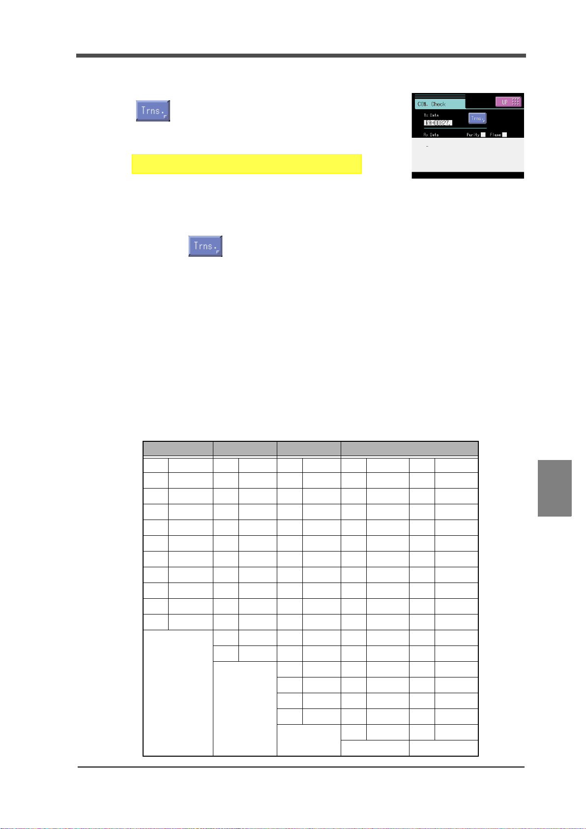
8 SUPPLEMENTS
SET. COM Check
→
Self Check
→
⑥COM check
The data displayed under "Transmit data" is sent by pressing the
button.
Under "Receive data", externally transmitted data is displayed.
How to set
Please transmit something information sentence from connected equipment side to the check on the
reception. The data received to "Receive data" is displayed. Please confirm the cable or the setting of
communication condition when it is not correctly displayed, when "Parity" or "Frame" lights in red.
Please press button to the check on the transmission. The data displayed in "Transmit
data" is transmitted. It will be confirmed to receive it correctly on connected equipment side. Please
confirm the cable or the setting of communication condition when it is not possible to confirm it.
■Password
This setting is for maintenance and inspection. Do not operate.
8-4. Unit Setting List
* The numbers correspond to the values in the input range of RS-232C.
Also, "0" means no unit.
Mass Force Pressure Others
1 μg12μN25μPa 42 kgm 60 kg/min
2 mg 13 mN 26 mPa 43 gcm 61 t/min
3g 14N 27Pa 44g/cm
4kg 15kN 28hPa 45kg/m
5Mg 16MN 29kPa 46t/m364 t/h
6t 17μNm 30 MPa 47 g/l 65 m3/s
7 lb 18 mNm 31 GPa 48 g/ml 66 m
8dyne 19Nm 32N/m249 mg/m 67 m3/h
9 kdyne 20 kNm 33 μbar 50kg/m 68l/h
10 oz 21 MNm 34 mbar 51 kgm/s 69 l/min
11 TONNE 22 ftlb 35 bar 52 kgm
23 inlb 36 mmHg 53 kgm
24 inoz 37 inH
3
62 kg/h
3
63 kg/s
2
/s 70 l/s
2
71
%
O 54mPas 72km
2
38 ftH2O 55 Pas 73 m
39 psia 56 m/s 74 cm
40 psig 57 km/h 75 mm
41 atom 58 m/s
59 t/s 77 rpm
2
76 μm
3
/min
Chapter
8
SUPPLEMENTS
91
91
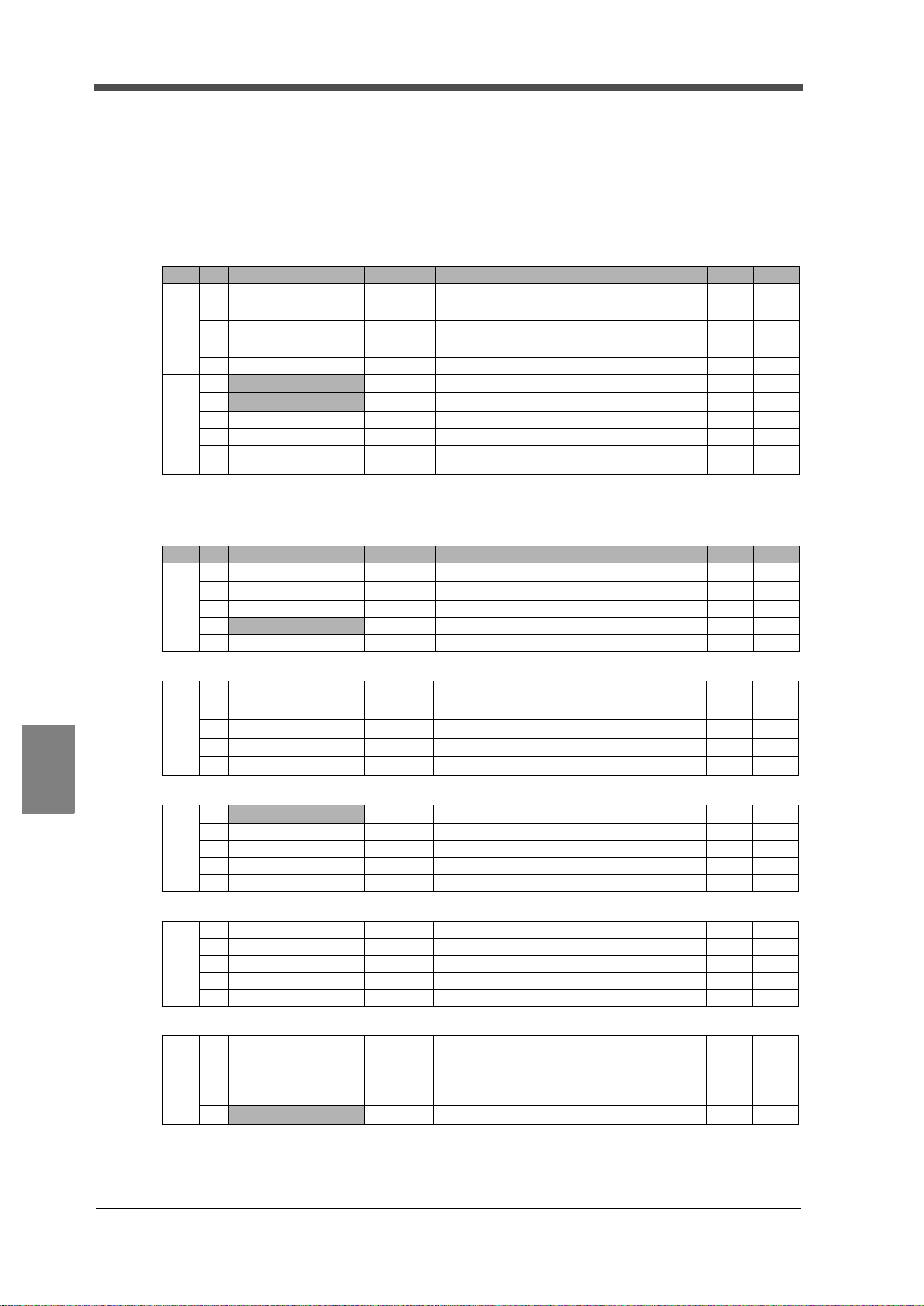
8 SUPPLEMENTS
8-5. Setting Item List
■Work setting Comparison setting (WORK0 to WORK15)
Protect ○:Work Setting Protect, ◎:System Setting Protect, ●:Calibration Protect, レ:Expansion Protect
Memory S:SRAM, N:NOVRAM
Page No. Item Initial value Setting range Memory Protect
1 HH Limit 8000
2 HI Limit 6000
1
3 LO Limit 4000
4 LL Limit 2000
5 Hysteresis 0 0 to 9999 S
6
Alarm HI Limit 99999
7
Alarm LO Limit
8 Near Zero 100 0 to 99999 S
2
9 Comparison Timing 0: ALL 0: ALL 1: MD 2: NZ 3: MD+NZ 4: HOLD S
Comparison Output
10
Selection
- 99999 - 99999 to 99999
2: H2/L2 *1 S
1 0: H4/L0 1: H3/L1 2: H2/L2 3: H1/L3 4: H0/L4
*
- 99999 to 99999
- 99999 to 99999
- 99999 to 99999
- 99999 to 99999
- 99999 to 99999
S
○
S
○
S
○
S
○
○
S
○
S
○
○
○
○
Chapter
8
SUPPLEMENTS
■Work setting Hold setting (WORK0 to WORK15)
Page No. Item Initial value Setting range Memory Protect
1 Hold Mode OFF
2 Hold Start Level 100
1
3 Section Time 1.000 sec 0.001 to 9.999 sec S
4
Level detection conditions 0 :Passed 0: Passed 1: Passed HI 2: Passed LO S
5
-Sample hold-
6 Sample Removal Value 0
7
2
8
9
10
-Peak hold or Valley hold, and Section setting; Level-
6
Hold Stop Level 100
7
2
8
9
10
-Average hold-
6 Average Sample Number 1 1 to 999 S
7
2
8
9
10
*2 *3
- 99999 to 99999
- 999 to 999
- 99999 to 99999
S
○
S
○
○
○
S
○
S
○
○
92
92
-Inflection Point hold-
6 Inflection Minimum Slope 30 1 to 99999 S
7 Inflection Front Slope Time 200 10 to 990 (Front slope time + rear slope time < 1000) S
8 Inflection Rear Slope Time 200 10 to 990 (Front slope time + rear slope time < 1000) S
2
9 Inflection Removal Value 0
10
Detection Start Condition 0: Ext+Level
- 999 to 999
0: Ext+Level 1: Ext Only
○
○
○
S
○
S
○
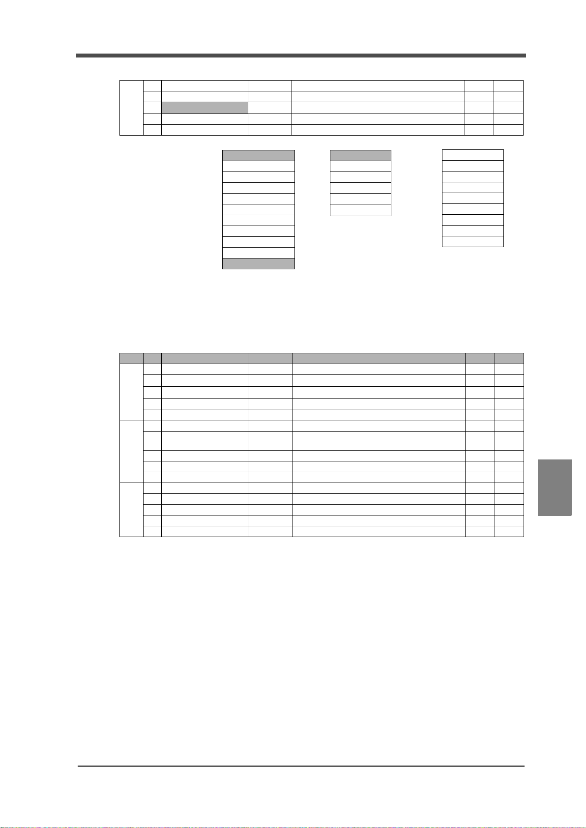
-Relative Maximum / Relative Minimum / Relative Difference hold-
*2
Hold
0:OFF
1:Sample
2:Peak
3:Valley
4:P-P
5:Average
6:Inflection Point
7:Relative Maximum
8:Relative Minimum
9:Relative Difference
*3
Hold Section
0:All
1:EXT
2:EXT+TM
3:LVL+TM
4:LVL *
* Selectable only for Peak
or Valley.
*4
0:x0.25
1:x0.50
2:x0.75
3:x1.00
4:x1.25
5:x1.50
6:x2.00
7:x3.00
8:x4.00
6 Relative Minimum Count 10 1 to 99999 S
7 Relative magnification ×1.00 * 4 S
8
2
Detection Start Condition 0: Ext+Level
9
10
0: Ext+Level 1: Ext Only
■Work setting Graph setting (WORK0 to WORK15)
8 SUPPLEMENTS
○
○
S
○
Protect ○:Work Setting Protect, ◎:System Setting Protect, ●:Calibration Protect, レ:Expansion Protect
Memory S:SRAM, N:NOVRAM
Page No. Item Initial value Setting range Memory Protect
1 Graph Mode 0: Continued 0: Continued 1: Ext 2: Level 3: Ext+Level S
2 Y(LD) Start Point 0
3 Y(LD) End Point 10000
1
4 X(TM) End Point 10.0 sec 0.1 to 99.9 sec S
5 Graph Start Level 100
6 Interval Time 1.00 sec 0.0 to 99.9 sec S
7 Level detection conditions 1: Passed HI
2
8
9
10
11
12
3
13
14
15
0: Passed 1: Passed HI 2: Passed LO 3: Beyond
4: Below
- 99999 to 99999
- 99999 to 99999
- 99999 to 99999
S
S
S
S
○
○
○
○
○
○
○
Chapter
8
SUPPLEMENTS
93
93
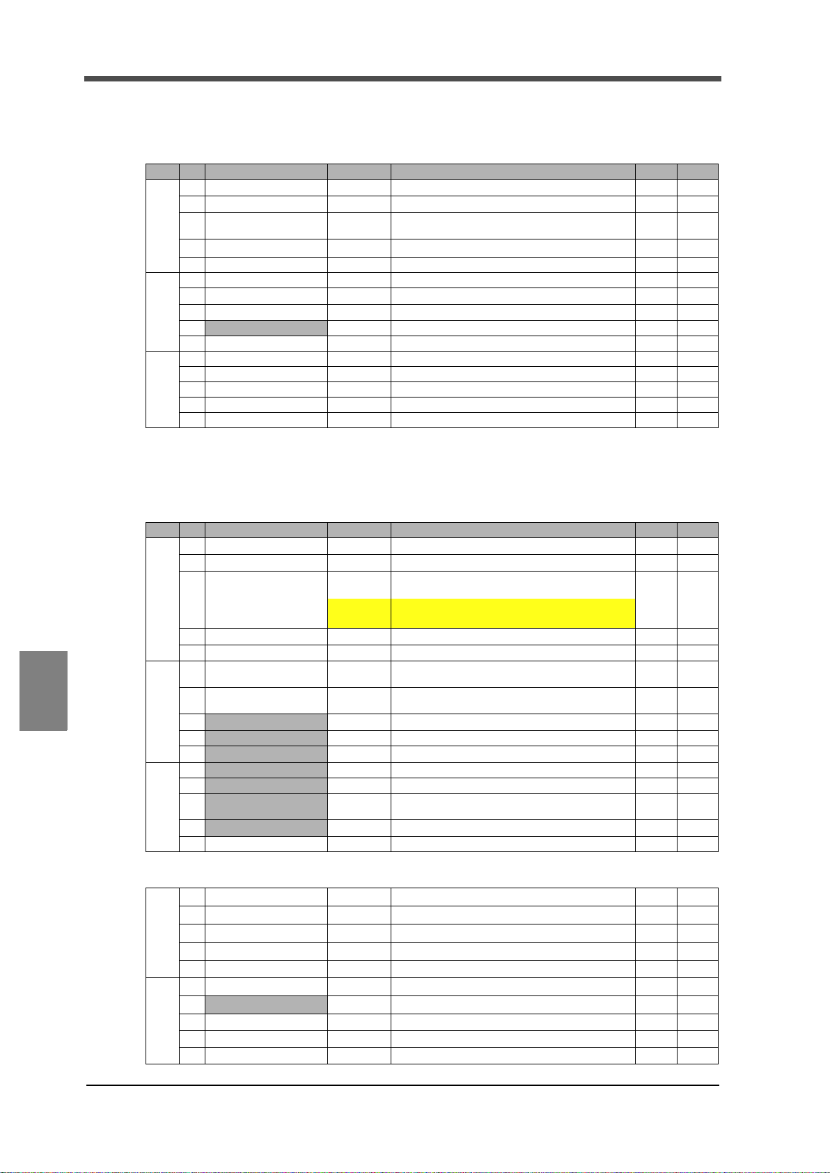
8 SUPPLEMENTS
■Calibration (CAL0 to CAL3)
Protect ○:Work Setting Protect, ◎:System Setting Protect, ●:Calibration Protect, レ:Expansion Protect
Memory S:SRAM, N:NOVRAM
Page No. Item Initial value Setting range Memory Protect
1 Excitation Voltage 0: 2.5V
2 Zero Calibration 0
1
2
3
Equivalent Input
3
Calibration
4 Actual Load Calibration 10000
5 Calibration Selecttion 0: Cal 0 0: Cal 0 1: Cal 1 2: Cal 2 3: Cal 3 4: EXT 0 N
6Unit kN *2 N
7 Increment 0: 1
8 Digital Offset 0
9
Digital Zero Limit 99999 0 to 99999 N
10 Calibration Selecttion 0: Cal 0 0: Cal 0 1: Cal 1 2: Cal 2 3: Cal 3 4: EXT 0 N
11
12
13
14
15
3.000mV/V
- 3.000mV / V to 3.000mV / V (0 is excluded.)
- 99999 to 99999
0: 1 1: 2 2: 5 3: 10 4: 20 5: 50 6: 100
*1 Calibration is bipolar. *2 See page91 "Unit Setting List".
0: 2.5V 1: 10V
- 3.000mV / V to 3.000mV / V
*1
(0 is excluded.)
- 99999 to 99999
N
●
N
●
N
●
N
●
●
●
N
●
N
●
●
●
Chapter
8
SUPPLEMENTS
■System setting
Operation Setting
Page No. Item Initial value Setting range Memory Protect
1 Digital Filter OFF
2 Analog Filter 2: 300Hz
1
3 Backlight
4 Language
5 SI/F Print Out OFF
6 Motion Detect
7 Zero Tracking
2
8
Vol. Out Filter 1: ON
9
Indicate Color Yellow 0: Yellow 1: Green 2: Blue 3: Comparison N
10
B5 Func. Select 0: WORK 3
11
B6 OFF Det. Wait 0.00 sec 0.00 to 1.00 sec N
12
B8 OFF Det. Wait 0.00 sec 0.00 to 1.00 sec N
Measurement work
13
3
selection
14
Control input selection 1: EXT.
15 Password
RS-232C Setting
1 Communication Mode 0: Normal
2 Baudrate 1: 19200bps
3 Data Bit 1: 8bit
1
4Stop Bit 0: 1bit
5 Parity Bit 1: EVEN
6 Delimiter 0: CR
7
Flow Control 0: OFF
2
8
9
10
ON time:
10 Min
Bright → Dark:
0 Min
0: JPN( 日) 0: JPN( 日) 1:ENG( 英 )
0.0 sec /
0count
0.0 sec /
0count
0: WORK 3 1: DSP_LOCK 2: KEY_LOCK
1: EXT.
0: 9600 1: 19200 2: 38400 3: 57600 [bps]
0: OFF,2 to 999 Times
0: 30 1: 100 2: 300 3: 1000 [Hz]
0 to 99 Min (Always ON time when "0".)
0 to 99 Min (Always Bright when "0")
0: OFF 1: MD 2: HOLD
0.0 to 9.9 sec / 0 to 99 count N
0.0 to 9.9 sec / 0 to 99 count N
0: OFF 1: ON
0: COM. 1: EXT.
0: COM. 1: EXT.
0: Normal 1: Continue 2: Print
0: 7bit 1: 8bit
0: 1bit 1: 2bit
0: NONE 1: EVEN 2: ODD
0: CR 1: CR+LF
0: OFF 1: RTS/CTS
*
N
◎
N
◎
N
◎
N
◎
N
◎
◎
◎
N
◎
◎
N
◎
◎
◎
N
◎
N
◎
N
◎
N
◎
N
◎
N
◎
N
◎
N
◎
N
◎
94
94

11
12
13
3
14
15
Option setting BCD output
1 BCD Output Select 1: Hold
2 BCD Output Rate 3: 100 /s
1
3 BCD Self Check
4
5
Option setting D/A output
1 Output Select 1: Hold 0: Real Time 1: Hold 2: Zero Scale 4: Full Scale N
2
3 Zero Scale 0
1
4 Full Scale 10000
5
Scale Set. Select 0 0 to 3 N
Option setting CC-Link
1 Station No. 2: 4 Station
2 Baudrate 4: 10M
1
3 ID 1 1 to 64 Station / 1 to 63 Station / 1 to 61 Station N
4
5
8 SUPPLEMENTS
0: Realtime 1: Hold 2: EXT.
0: 10 1: 20 2: 50 3: 100 4: 200 5: 500 6: 1000 7: 2000 [ /s]
- 99999 to 99999
- 99999 to 99999
0: 1Station 1: 2 Station 2: 4 Station
0: 156k 1: 625k 2: 2.5M 3: 5M 4: 10M
N
◎
N
◎
◎
N
◎
N
◎
◎
N
◎
N
◎
◎
Option setting DeviceNet
1 Possession Node 0: 2 Node 0: 2 Node 1: 4 Node N
2 Node Address 0 0 to 63 N
3 Major Revision 1
1
4
5
1,2
N
■Protect / Initialization
Protect ○:Work Setting Protect, ◎:System Setting Protect, ●:Calibration Protect, レ:Expansion Protect
Memory S:SRAM, N:NOVRAM
Page No. Item Initial value Setting range Memory Protect
1 Work Protect 0: OFF
System Protect
2
3 Calibration Protect 0: OFF
1
4 Expansion Protect 1: ON
5 Initialization 0: Work Set.
0: OFF
0: OFF 1: ON
0: OFF 1: ON
0: OFF 1: ON
0: OFF 1: ON
Work Set. 1: Sys. Set. 2: Cal. Set. 3: Exp. Set.
0:
N
N
N
N
■Self check
Page No. Item Initial value Setting range Memory Protect
1 LCD Check
KEY Check
2
3MEM Check
1
4 I/O Check
5DSP Check
6COM Check
◎
◎
◎
Chapter
8
SUPPLEMENTS
95
* Shaded parts indicate newly-added setting items to F370/F371.
Shaded* parts indicate newly-added setting items to F372.
95

8 SUPPLEMENTS
M E M O
Chapter
8
SUPPLEMENTS
96
96

EXPANSION
97
97

M E M O
98
98
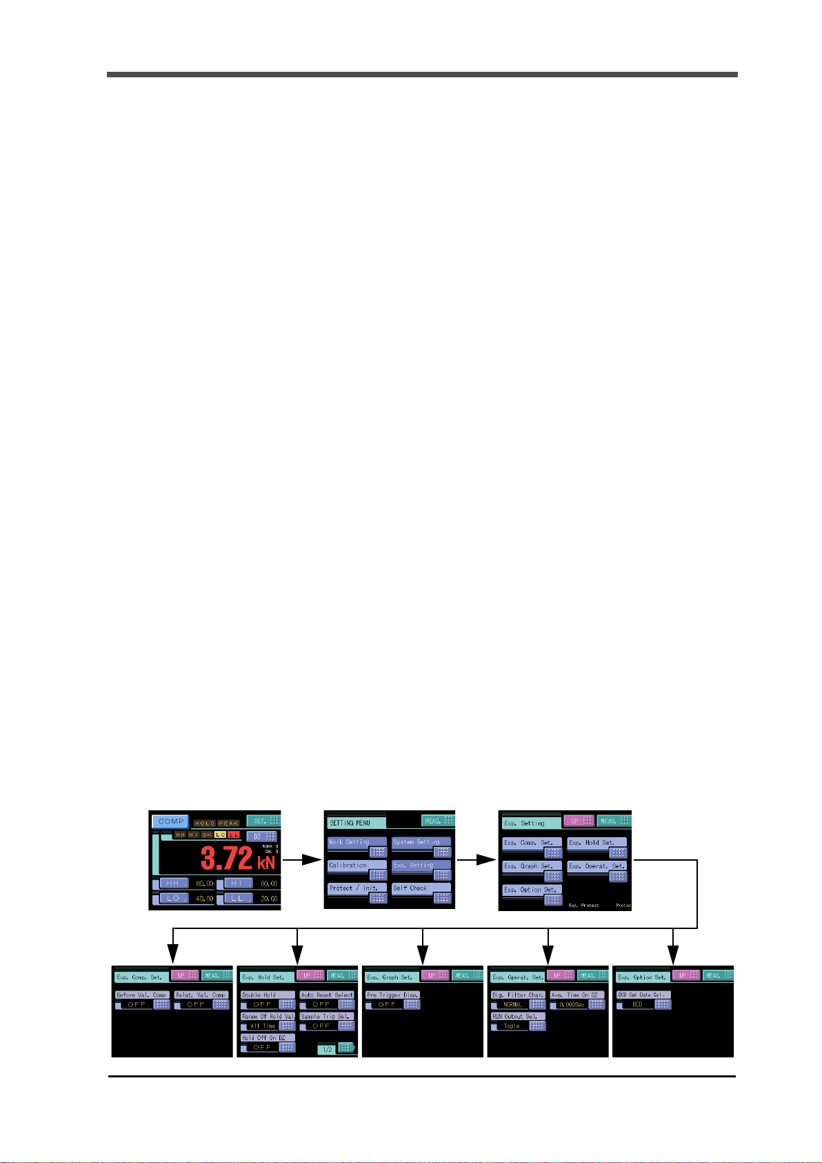
Expansion Function
Expansion Function
The indicator is designed so as to be able to perform more operations by selecting the following functions
from the Expansion menu.
Expansion Comparison Setting ● Before Value Comparison (P120)
Expansion Hold Setting ● Double Hold (P101)
Expansion Graph Setting ● Pre Trigger Display (P130)
Expansion Function
● Relative Value Comparison (P124)
● Auto Reset Select (P116)
● Renewal Of Hold Value (P118)
● Sample Trigger Selection (P114)
● Hold Off On Digital Zero (P117)
● Hold End Timing (P119)
Expansion Operation Setting ● Digital Filter Character (P131)
● Average Time On Digital Zero (P131)
● RUN Output Selection (P132)
Expansion Option Setting ● BCD Output Data Selection (P133)
Data of measurement values newly obtained by selecting and operating the expansion functions can also
be taken out externally through standard and option interfaces.
Standard interfaces ● SI/F (P134)
● RS-232C (P134)
Option interfaces ● BCD OUTPUT (P141)
● DAC OUTPUT (P142)
● CC-Link (P142)
● DeviceNet (P142)
Expansion Setting menu
99
99
 Loading...