

Page 1

F370
DIGITAL INDICATOR
OPERATION MANUAL
20 Jul. 2011
Rev. 1.19
Page 2

Cautions and Requests for Use
● Do not disassemble the main body for modifications or repair.
● Be sure to use crimp contacts for connection to terminal blocks, and do not to
connect bare wires as they are.
● Be sure to ground the protective ground terminal.
● Be sure to disconnect the power cable when performing the following.
- Attachment/detachment of connectors of options.
- Wiring/connection of cables to terminal blocks.
- Connection of the ground line.
Cautions and Requests for Use
● Carefully check wiring, etc. before applying power.
● Take an interval of more than 5 seconds when repeating ON/OFF.
● Take adequate shielding measures when using at the following locations.
- Near a power line.
- Where a strong electric field or magnetic field is formed.
- Where static electricity, relay noise or the like is generated.
● Do not install in the following environments.
- Places exposed to direct sunlight.
- Where the temperature and/or humidity exceeds the range in the
specifications.
- Places containing corrosive gas or flammable gas.
- Places with large quantities of dust, salt or iron powder.
- Where the product may be splashed with water, oil or chemicals.
- Where the main body is directly affected by vibration or shock.
● Set the correct Excitation Voltage for the sensor. (2.5V is set when F370 is
dispatched from us.)
Page 3

Safety Precautions
WARNING
Misuse may cause the risk of death or serious
injury to persons.
Misuse may cause the risk of injury to persons or
damage to property.
CAUTION
Safety Precautions
● Indications for safe use and their meanings
In this manual, precautions for using the F370 digital indicator safely are indicated as
follows. Be sure to follow the precautions given here because they are important
descriptions relating to safety.
Indications and their meanings are as follows:
● Explanation of pictographs
The △ means a caution (or warning).
A specific description is written in the △ .
The illustration on the left-hand side shows "Caution: May explode".
The △ means a caution (or warning).
A specific description is written in the △ .
The illustration on the left-hand side shows a general caution.
Page 4

● About the built-in lithium battery
Never disassemble, deform under pressure or throw the battery
into fire.The battery may explode, catch fire or leak.
- Battery
Model: CR2477-1HF made by Matsushita Battery Industrial Co., Ltd.
Nominal voltage: 3V
Nominal electric capacity: 1000mAh
WARNING
For connection to the signal I/O terminal block, wire correctly after
checking the signal names and terminal block numbers.
Also, turn off the power of the main body before connection/wiring to the
signal I/O terminal block.
CAUTION
Safety Precautions
● About the signal I/O terminal block
Page 5

CONTENTS
CONTENTS
1.APPEARANCE DESCRIPTION . . . . . . . . . . . . . . . . . . . . . . . . .1
1-1.Front Panel . . . . . . . . . . . . . . . . . . . . . . . . . . . . . . . . . . . . . . . . . . . .1
1-1-1.Touch Panel Display . . . . . . . . . . . . . . . . . . . . . . . . . . . . . . . . . . . . . . . . . . . . . 1
1-1-2.Power Lamp . . . . . . . . . . . . . . . . . . . . . . . . . . . . . . . . . . . . . . . . . . . . . . . . . . . 1
1-2.Rear Panel . . . . . . . . . . . . . . . . . . . . . . . . . . . . . . . . . . . . . . . . . . . . .2
1-2-1.Signal I/O Terminal Block . . . . . . . . . . . . . . . . . . . . . . . . . . . . . . . . . . . . . . . . . 2
1-2-2.AC Power Source Input Terminal Block . . . . . . . . . . . . . . . . . . . . . . . . . . . . . . 4
1-2-3.Frame Ground (Functional ground) . . . . . . . . . . . . . . . . . . . . . . . . . . . . . . . . . 4
1-2-4.Optional Slot . . . . . . . . . . . . . . . . . . . . . . . . . . . . . . . . . . . . . . . . . . . . . . . . . . . 4
2.SETTING MODES . . . . . . . . . . . . . . . . . . . . . . . . . . . . . . . . . . .5
2-1.F370 Screen Configuration . . . . . . . . . . . . . . . . . . . . . . . . . . . . . . . .5
2-2.Setting Modes Tree . . . . . . . . . . . . . . . . . . . . . . . . . . . . . . . . . . . . . .6
2-3.About a Setting Call . . . . . . . . . . . . . . . . . . . . . . . . . . . . . . . . . . . . . .8
3.CONNECTION . . . . . . . . . . . . . . . . . . . . . . . . . . . . . . . . . . . . . .9
3-1.Connection with Power Source Input Terminal . . . . . . . . . . . . . . . . .9
3-2.Load Cell Connection . . . . . . . . . . . . . . . . . . . . . . . . . . . . . . . . . . .10
3-3.SI/F Connection . . . . . . . . . . . . . . . . . . . . . . . . . . . . . . . . . . . . . . . .11
3-4.External I/O Connection . . . . . . . . . . . . . . . . . . . . . . . . . . . . . . . . . .12
3-4-1.External Output Connection . . . . . . . . . . . . . . . . . . . . . . . . . . . . . . . . . . . . . . 12
3-4-2.External Input Connection . . . . . . . . . . . . . . . . . . . . . . . . . . . . . . . . . . . . . . . 12
3-4-3.Connecting to Cage Clamp Terminal Block . . . . . . . . . . . . . . . . . . . . . . . . . . 13
4.CALIBRATION . . . . . . . . . . . . . . . . . . . . . . . . . . . . . . . . . . . . .14
4-1.Equivalent Input Calibration Procedure . . . . . . . . . . . . . . . . . . . . . .15
4-2.Actual Load Calibration Procedure . . . . . . . . . . . . . . . . . . . . . . . . .16
4-3.Zero Calibration . . . . . . . . . . . . . . . . . . . . . . . . . . . . . . . . . . . . . . . .17
4-4.Actual Load Calibration . . . . . . . . . . . . . . . . . . . . . . . . . . . . . . . . . .18
Page 6

CONTENTS
4-5.Equivalent Input Calibration . . . . . . . . . . . . . . . . . . . . . . . . . . . . . . .19
4-6.Digital Offset . . . . . . . . . . . . . . . . . . . . . . . . . . . . . . . . . . . . . . . . . .21
4-7.Increment (This step may be omitted if there is no change.) . . . . . .22
4-8.Decimal Place . . . . . . . . . . . . . . . . . . . . . . . . . . . . . . . . . . . . . . . . .23
4-9.Calibration Protection . . . . . . . . . . . . . . . . . . . . . . . . . . . . . . . . . . .24
4-10.Calibration Value Selection . . . . . . . . . . . . . . . . . . . . . . . . . . . . . .25
4-11.Unit . . . . . . . . . . . . . . . . . . . . . . . . . . . . . . . . . . . . . . . . . . . . . . . .27
5.SETTING OF FUNCTIONS . . . . . . . . . . . . . . . . . . . . . . . . . . .28
5-1.Digital Zero . . . . . . . . . . . . . . . . . . . . . . . . . . . . . . . . . . . . . . . . . . .28
5-2.Digital Filter . . . . . . . . . . . . . . . . . . . . . . . . . . . . . . . . . . . . . . . . . . .29
5-3.Analog Filter . . . . . . . . . . . . . . . . . . . . . . . . . . . . . . . . . . . . . . . . . . .30
5-4.Display Rate . . . . . . . . . . . . . . . . . . . . . . . . . . . . . . . . . . . . . . . . . .30
5-5.Stability . . . . . . . . . . . . . . . . . . . . . . . . . . . . . . . . . . . . . . . . . . . . . .31
5-6.Zero Track . . . . . . . . . . . . . . . . . . . . . . . . . . . . . . . . . . . . . . . . . . . .32
5-7.Contrast Adjustment . . . . . . . . . . . . . . . . . . . . . . . . . . . . . . . . . . . .33
5-8.Backlight . . . . . . . . . . . . . . . . . . . . . . . . . . . . . . . . . . . . . . . . . . . . .33
5-9.Excitation Voltage . . . . . . . . . . . . . . . . . . . . . . . . . . . . . . . . . . . . . .33
5-10.Auto Print . . . . . . . . . . . . . . . . . . . . . . . . . . . . . . . . . . . . . . . . . . . .34
5-11.Hold Off Print . . . . . . . . . . . . . . . . . . . . . . . . . . . . . . . . . . . . . . . . .36
5-12.Parameter Protection . . . . . . . . . . . . . . . . . . . . . . . . . . . . . . . . . . .36
6.COMPARISON FUNCTIONS . . . . . . . . . . . . . . . . . . . . . . . . . .37
6-1.HI Limit/LO Limit/HI-HI Limit/LO-LO Limit . . . . . . . . . . . . . . . . . . . .38
6-2.Hysteresis . . . . . . . . . . . . . . . . . . . . . . . . . . . . . . . . . . . . . . . . . . . .39
6-3.Near Zero . . . . . . . . . . . . . . . . . . . . . . . . . . . . . . . . . . . . . . . . . . . . .41
6-4.HI-LO Limit Comparison Mode . . . . . . . . . . . . . . . . . . . . . . . . . . . .41
6-5.HI-LO Limit Output Mode . . . . . . . . . . . . . . . . . . . . . . . . . . . . . . . . .42
6-6.Alarm Mode . . . . . . . . . . . . . . . . . . . . . . . . . . . . . . . . . . . . . . . . . . .43
Page 7

CONTENTS
7.HOLD FUNCTIONS . . . . . . . . . . . . . . . . . . . . . . . . . . . . . . . . .44
7-1.Hold Setting --- common --- . . . . . . . . . . . . . . . . . . . . . . . . . . . . . .44
7-1-1.Hold Mode . . . . . . . . . . . . . . . . . . . . . . . . . . . . . . . . . . . . . . . . . . . . . . . . . . . 44
7-1-2.Hold Detection Time . . . . . . . . . . . . . . . . . . . . . . . . . . . . . . . . . . . . . . . . . . . . 45
7-1-3.Auto Start Level . . . . . . . . . . . . . . . . . . . . . . . . . . . . . . . . . . . . . . . . . . . . . . . 46
7-1-4.Hold Point Shift . . . . . . . . . . . . . . . . . . . . . . . . . . . . . . . . . . . . . . . . . . . . . . . . 46
7-2.Hold Setting --- relative maximum and relative minimum --- . . . . .47
7-2-1.Minimum Count . . . . . . . . . . . . . . . . . . . . . . . . . . . . . . . . . . . . . . . . . . . . . . . 48
7-2-2.Valley Detection Level . . . . . . . . . . . . . . . . . . . . . . . . . . . . . . . . . . . . . . . . . . 48
7-3.Hold Setting --- inflection point --- . . . . . . . . . . . . . . . . . . . . . . . . .49
7-3-1.Minimum Slope . . . . . . . . . . . . . . . . . . . . . . . . . . . . . . . . . . . . . . . . . . . . . . . . 50
7-3-2.Interval A and Interval B . . . . . . . . . . . . . . . . . . . . . . . . . . . . . . . . . . . . . . . . . 50
7-4.Hold Setting --- mean value --- . . . . . . . . . . . . . . . . . . . . . . . . . . .52
7-4-1.Mean Value Sampling Count . . . . . . . . . . . . . . . . . . . . . . . . . . . . . . . . . . . . . 52
7-5.Hold Operation . . . . . . . . . . . . . . . . . . . . . . . . . . . . . . . . . . . . . . . . .53
7-5-1.Sample Hold . . . . . . . . . . . . . . . . . . . . . . . . . . . . . . . . . . . . . . . . . . . . . . . . . . 53
7-5-2.Peak Hold . . . . . . . . . . . . . . . . . . . . . . . . . . . . . . . . . . . . . . . . . . . . . . . . . . . . 54
7-5-3.Valley Hold . . . . . . . . . . . . . . . . . . . . . . . . . . . . . . . . . . . . . . . . . . . . . . . . . . . 55
7-5-4.Peak-to-Peak (P-P) Hold . . . . . . . . . . . . . . . . . . . . . . . . . . . . . . . . . . . . . . . . 56
7-5-5.Relative Maximum and Relative Minimum Hold . . . . . . . . . . . . . . . . . . . . . . . 57
7-5-6.Inflection Point Hold . . . . . . . . . . . . . . . . . . . . . . . . . . . . . . . . . . . . . . . . . . . . 59
7-5-7.Mean Value Hold . . . . . . . . . . . . . . . . . . . . . . . . . . . . . . . . . . . . . . . . . . . . . . 60
7-6.How to Specify the Hold Detection Period . . . . . . . . . . . . . . . . . . . .61
7-6-1.All Period . . . . . . . . . . . . . . . . . . . . . . . . . . . . . . . . . . . . . . . . . . . . . . . . . . . . 61
7-6-2.Externally Specified Period Hold
(Peak, Valley, Peak-to-Peak and Mean Value) . . . . . . . . . . . . . . . . . . . . . . . 62
7-6-3.Time Specified Period Hold
(Peak, Valley, Peak-to-Peak and Mean Value) . . . . . . . . . . . . . . . . . . . . . . . 63
7-6-4.Time Specified Period Hold with Trigger
(Peak, Valley, Peak-to-Peak and Mean Value) . . . . . . . . . . . . . . . . . . . . . . . 64
8.MULTI-HOLD FUNCTION . . . . . . . . . . . . . . . . . . . . . . . . . . . .65
8-1.About Changing of the Setting CH . . . . . . . . . . . . . . . . . . . . . . . . . .66
Page 8

CONTENTS
9.WAVEFORM DISPLAY . . . . . . . . . . . . . . . . . . . . . . . . . . . . . .67
9-1.Graphic Display Screen . . . . . . . . . . . . . . . . . . . . . . . . . . . . . . . . . .67
9-1-1.Hold Point Plotting . . . . . . . . . . . . . . . . . . . . . . . . . . . . . . . . . . . . . . . . . . . . . 68
9-1-2.X-axis and Y-axis on the Graph Plotting Screen . . . . . . . . . . . . . . . . . . . . . . 68
9-2.Graph Plotting . . . . . . . . . . . . . . . . . . . . . . . . . . . . . . . . . . . . . . . . .69
9-2-1.Continuous . . . . . . . . . . . . . . . . . . . . . . . . . . . . . . . . . . . . . . . . . . . . . . . . . . . 69
9-2-2.External . . . . . . . . . . . . . . . . . . . . . . . . . . . . . . . . . . . . . . . . . . . . . . . . . . . . . 70
9-2-3.Level . . . . . . . . . . . . . . . . . . . . . . . . . . . . . . . . . . . . . . . . . . . . . . . . . . . . . . . . 71
9-2-4.External + Level . . . . . . . . . . . . . . . . . . . . . . . . . . . . . . . . . . . . . . . . . . . . . . . 71
9-3.Graph Function . . . . . . . . . . . . . . . . . . . . . . . . . . . . . . . . . . . . . . . .72
9-4.Interval Time . . . . . . . . . . . . . . . . . . . . . . . . . . . . . . . . . . . . . . . . . .72
9-5.Graph Start Level . . . . . . . . . . . . . . . . . . . . . . . . . . . . . . . . . . . . . . .72
9-6.Level Detection Mode . . . . . . . . . . . . . . . . . . . . . . . . . . . . . . . . . . .73
9-7.X Start Point . . . . . . . . . . . . . . . . . . . . . . . . . . . . . . . . . . . . . . . . . . .74
9-8.Y (Load) Start Point and Y (Load) End Point . . . . . . . . . . . . . . . . . .74
10.BCD DATA OUTPUT(OPTION) . . . . . . . . . . . . . . . . . . . . . . .75
10-1.Connector Pin Assignment . . . . . . . . . . . . . . . . . . . . . . . . . . . . . .75
10-2.Logic Change . . . . . . . . . . . . . . . . . . . . . . . . . . . . . . . . . . . . . . . . .76
10-3.BCD Data Hold . . . . . . . . . . . . . . . . . . . . . . . . . . . . . . . . . . . . . . .76
10-4.Equivalent Circuit . . . . . . . . . . . . . . . . . . . . . . . . . . . . . . . . . . . . . .76
10-5.Signal Timing . . . . . . . . . . . . . . . . . . . . . . . . . . . . . . . . . . . . . . . . .77
10-6.BCD Data Update Rate Selection . . . . . . . . . . . . . . . . . . . . . . . . .78
10-7.BCD Output Data Selection . . . . . . . . . . . . . . . . . . . . . . . . . . . . . .78
11.RS-232C INTERFACE(OPTION) . . . . . . . . . . . . . . . . . . . . . .79
11-1.Communication Specifications . . . . . . . . . . . . . . . . . . . . . . . . . . . .79
11-1-1.Specifications . . . . . . . . . . . . . . . . . . . . . . . . . . . . . . . . . . . . . . . . . . . . . . . . 79
11-1-2.Connector Pin Assignment . . . . . . . . . . . . . . . . . . . . . . . . . . . . . . . . . . . . . . 80
11-1-3.Cable . . . . . . . . . . . . . . . . . . . . . . . . . . . . . . . . . . . . . . . . . . . . . . . . . . . . . . 80
Page 9

CONTENTS
11-2.RS-232C Interface Setting . . . . . . . . . . . . . . . . . . . . . . . . . . . . . . .81
11-2-1.Communication Mode . . . . . . . . . . . . . . . . . . . . . . . . . . . . . . . . . . . . . . . . . . 81
11-2-2.Baud Rate . . . . . . . . . . . . . . . . . . . . . . . . . . . . . . . . . . . . . . . . . . . . . . . . . . . 81
11-2-3.Character Length . . . . . . . . . . . . . . . . . . . . . . . . . . . . . . . . . . . . . . . . . . . . . 81
11-2-4.Parity Bit . . . . . . . . . . . . . . . . . . . . . . . . . . . . . . . . . . . . . . . . . . . . . . . . . . . . 81
11-2-5.Stop Bit . . . . . . . . . . . . . . . . . . . . . . . . . . . . . . . . . . . . . . . . . . . . . . . . . . . . . 82
11-2-6.Terminator . . . . . . . . . . . . . . . . . . . . . . . . . . . . . . . . . . . . . . . . . . . . . . . . . . 82
11-3.Communication Modes . . . . . . . . . . . . . . . . . . . . . . . . . . . . . . . . .82
11-4.Communication Format . . . . . . . . . . . . . . . . . . . . . . . . . . . . . . . . .83
12.RS-485 COMMUNICATION INTERFACE(OPTION) . . . . . . .90
12-1.Communication Specifications . . . . . . . . . . . . . . . . . . . . . . . . . . . .90
12-2.RS-485 connection . . . . . . . . . . . . . . . . . . . . . . . . . . . . . . . . . . . .90
12-3.Communication Method . . . . . . . . . . . . . . . . . . . . . . . . . . . . . . . . .93
12-4.RS-485 Interface Setting . . . . . . . . . . . . . . . . . . . . . . . . . . . . . . . .94
12-4-1.ID . . . . . . . . . . . . . . . . . . . . . . . . . . . . . . . . . . . . . . . . . . . . . . . . . . . . . . . . . 94
12-4-2.Terminator Resistance . . . . . . . . . . . . . . . . . . . . . . . . . . . . . . . . . . . . . . . . . 94
12-4-3.Communication Method . . . . . . . . . . . . . . . . . . . . . . . . . . . . . . . . . . . . . . . . 94
13.D/A CONVERTER(OPTION) . . . . . . . . . . . . . . . . . . . . . . . . .95
13-1.Voltage Zero and Full Scale, Current Zero and Full Scale . . . . . .96
13-2.D/A Output Mode . . . . . . . . . . . . . . . . . . . . . . . . . . . . . . . . . . . . . .97
13-3.Voltage Output Selection . . . . . . . . . . . . . . . . . . . . . . . . . . . . . . . .97
13-4.Current Output Selection . . . . . . . . . . . . . . . . . . . . . . . . . . . . . . . .97
14.DC POWER SOURCE . . . . . . . . . . . . . . . . . . . . . . . . . . . . . .99
15.ERROR MESSAGES . . . . . . . . . . . . . . . . . . . . . . . . . . . . . .100
Page 10

CONTENTS
16.SELF-CHECK AND INITIALIZATION . . . . . . . . . . . . . . . . .101
16-1.Self-Check . . . . . . . . . . . . . . . . . . . . . . . . . . . . . . . . . . . . . . . . . .101
16-1-1.Self-Check DSP . . . . . . . . . . . . . . . . . . . . . . . . . . . . . . . . . . . . . . . . . . . . . 101
16-1-2.Self-Check MEM . . . . . . . . . . . . . . . . . . . . . . . . . . . . . . . . . . . . . . . . . . . . . 101
16-1-3.Self-Check KEY . . . . . . . . . . . . . . . . . . . . . . . . . . . . . . . . . . . . . . . . . . . . . 102
16-1-4.Self-Check EXT . . . . . . . . . . . . . . . . . . . . . . . . . . . . . . . . . . . . . . . . . . . . . 102
16-2.Initialization (All setting value clearances) . . . . . . . . . . . . . . . . . .103
16-3.Password . . . . . . . . . . . . . . . . . . . . . . . . . . . . . . . . . . . . . . . . . . .103
17.ABOUT JAPANESE/ENGLISH DISPLAY SELECTION . . .104
18.BLOCK DIAGRAM . . . . . . . . . . . . . . . . . . . . . . . . . . . . . . . .105
19.DIMENSIONS . . . . . . . . . . . . . . . . . . . . . . . . . . . . . . . . . . . .106
20.INSTALLATION IN A PANEL . . . . . . . . . . . . . . . . . . . . . . .107
21.SPECIFICATIONS . . . . . . . . . . . . . . . . . . . . . . . . . . . . . . . .108
21-1.Analog Section . . . . . . . . . . . . . . . . . . . . . . . . . . . . . . . . . . . . . . .108
21-2.Digital Section . . . . . . . . . . . . . . . . . . . . . . . . . . . . . . . . . . . . . . .108
21-3.Options . . . . . . . . . . . . . . . . . . . . . . . . . . . . . . . . . . . . . . . . . . . .109
21-4.External Input and Output . . . . . . . . . . . . . . . . . . . . . . . . . . . . . .110
21-5.General . . . . . . . . . . . . . . . . . . . . . . . . . . . . . . . . . . . . . . . . . . . .111
21-6.Accessories . . . . . . . . . . . . . . . . . . . . . . . . . . . . . . . . . . . . . . . . .112
22.SETTING ITEM CHART . . . . . . . . . . . . . . . . . . . . . . . . . . . .113
23.CONFORMITY TO EC DIRECTIVES . . . . . . . . . . . . . . . . . .117
Page 11

CONTENTS
Page 12

1. APPEARANCE DESCRIPTION
Touch Panel
Display
Power Lamp
Hold Status Display
Display Change Button
Comparison Status
Indicated Value
Setting Input Screen
Call Button
Digital Zero
Button
Setting Mode
Button
Display
Display
Comparison Display Hold Display Graph Display
1-1. Front Panel
1.APPEARANCE DESCRIPTION
1-1-1. Touch Panel Display
This is the touch panel display for displaying an indicated value and graph set value and
for setting various setting items of the F370. During measurement, a comparison display,
hold display and graph display can be selected according to the function in use.
1-1-2. Power Lamp
This lamp lights when the power to the F370 is on.
1
Page 13

1.APPEARANCE DESCRIPTION
Frame ground
Signal I/O terminal
Optional slot
AC power source
input terminal block
block
1-2. Rear Panel
1-2-1. Signal I/O Terminal Block
D/Z In A11 B11 SIF Out
H/M In A10 B10 SIF Out
T/H In A9 B9 ST/SP In
CODE2 In A8 B8 CODE3 In
CODE0 In A7 B7 CODE1 In
COM2
※
HH Out A5 B5 LL Out
HI Out A4 B4 LO Out
COM1
※
-EXC Out A2 B2 -SIG In
Pin assignments
A6 B6 H/E Out
A3 B3 OK Out
2
+EXC Out A1 B1 +SIG In
Page 14

1.APPEARANCE DESCRIPTION
「COMPARISON
FUNCTIONS」
→
page 37
The input for controlling the hold signal.
→ page44「HOLD FUNCTIONS」
Caution
Use TMEV1.25-3S crimp contacts (attached) made by NTM or
equivalent for connection to the signal I/O terminal block and the
AC power source input terminal block.
+EXC
-EXC
+SIG
-SIG
See the section on Load Cell Connection page 10 for connection.
COM1 The terminal common to output signals.
OK
HI
LO
HH
LL
H/E Outputs the hold end signal.
See the section on External I/O Connection page 12 for connection.
COM2 The terminal common to input signals.
CODE0
CODE1
CODE2
CODE3
The terminal for connecting to a strain-gage sensor.
Outputs the OK signal.
Outputs the HI signal.
Outputs the LO signal.
Outputs the HH signal.
Outputs the LL signal.
→ page44「HOLD FUNCTIONS」
Selects the CH No. for the multi-hold function.
→ page65「MULTI-HOLD FUNCTION」
T/H
H/M
D/Z The input for digital zero (making the indicated value zero).
→ page28「Digital Zero」
ST/SP The graphic display start/stop signal.
→ page69「Graph Plotting」
See the section on External I/O Connection page 12 for connection.
SI/F The 2-wire serial interface for coupling a UNIPULSE printer,
external display, etc.
See the section on SI/F Connection page 11 for connection.
3
Page 15

1.APPEARANCE DESCRIPTION
1-2-2. AC Power Source Input Terminal Block
Connect the AC power cord. The input voltage is 100V - 240V AC, and the frequency is
50/60Hz.
1-2-3. Frame Ground (Functional ground)
This is a ground terminal block. Be sure to ground the F.G. terminal to prevent electric
shocks and failures due to static electricity.
1-2-4. Optional Slot
Any one of the following optional boards can be mounted.
• BCD data output
• RS-232C communication interface
• D/A converter
• RS-485
• CC-Link interface
(CC-Link is an abbreviation for "Control & Communication Link".)
• Device Net interface
4
Page 16

2. SETTING MODES
HOME
MODE
UP
Mode keys
Setting keys
HOME
HOME
Set value entry from
the ordinary display screen
UP
[Ordinary display screen]
[Mode selection screen]
[Set value selection screen]
[Set value entry screen]
With the NEXT key on the set value entry screen, the next set value entry screen appears.
2-1. F370 Screen Configuration
2.SETTING MODES
5
Page 17

2.SETTING MODES
ordinary display screen
Mode selection screen
OPERATION
PAGE1
Digital Filter (P29)
Analog Filter (P30)
Display Rate (P30)
Stability (Time) (P31)
Stability (Cnt) (P31)
PAGE2
Zero Track (Time) (P31)
Zero Track (Cnt) (P31)
Contrast1 (P33)
Contrast2 (P33)
Backlight (P33)
PAGE3
Ext Voltage (P33)
Auto Print (P34)
Hold Off Print (P36)
CAL. LOCK (P24)
PARA. LOCK (P36)
COMPARISON
PAGE1
HI_HI Limit (P38)
HI Limit (P38)
LO Limit (P38)
LO_LO Limit (P38)
Hysteresis (P39)
PAGE2
Near Zero (P41)
Comparison Func (P41)
Comparison Mode (P42)
Alarm Mode (P42)
HOLD
PAGE1
Hold Function (P44)
Hold Detect Time (P45)
Auto Start Level (P46)
Minimum Count (P48)
Valley Detect Lv1 (P48)
PAGE2
Minimum Slope (P50)
Interval A (P50)
Interval B (P50)
Hold Point Shift (P46)
Mean Value
Sampling Count (P52)
GRAPH
PAGE1
Graph Function (P72)
Interval Time (P72)
Graph Start Level (P72)
Level Detect Mode (P73)
X Start Point (P74)
PAGE2
Y Start Point (P74)
Y End Point (P74)
2-2. Setting Modes Tree
6
Page 18

2.SETTING MODES
CALIBRATION
PAGE1
Zero Cal. (P17)
Actual Cal. (P18)
Equiv. Cal. (P19)
CAL. Select (P25)
Increment (P22)
PAGE2
Unit (P27)
Decimal Place (P23)
Digital Offset (P21)
OPTION
A setting function changes
by the option.
SYSTEM
PAGE1
All Para. Clear (P103)
SelfCheck DSP (P101)
SelfCheck MEM (P101)
SelfCheck KEY (P102)
SelfCheck EXT (P102)
PAGE2
PASSWORD (P103)
LANGUAGE (P104)
BCD OUTPUT
PAGE1
BCD
Data Update Rate (P78)
BCD
Output Data Selection
(P78)
RS232C
PAGE1
Communication Mode
s (P81)
Baud Rate (P81)
Character Length (P81)
Parity Bit (P81)
Stop Bit (P82)
PAGE2
Terminator (P82)
D/AOutput
PAGE1
D/A Output Mode (P97)
D/A Zero Output (P96)
D/A Zero and Full Scale
(P96)
Current Zero Output (P96)
Current Zero and Full
(P96)
RS485
PAGE1
Communication Modes
(P81)
Baud Rate (P81)
Character Length (P81)
Parity Bit (P81)
Stop Bits (P82)
PAGE2
Terminator (P82)
ID (P94)
Terminator resistance
(P94)
Communication Method
(P94)
PAGE2
Voltage
Output Selection (P97)
Current
Output Selection (P97)
7
Page 19

2.SETTING MODES
Page 3
↑↑
Mode Page
→→
Setting call
Operation setting
Setting call
Can be changed
by the PAGE
・Operation setting ・Comparison setting
・Hold ・Graph setting
・Calibration ・Option
・System
Modes are as follows:
Operation setting
button.
PAG E
PAGE
Page 1 Page 2 Page 3
PAG E
2-3. About a Setting Call
In this manual, a setting function call is described as follows.
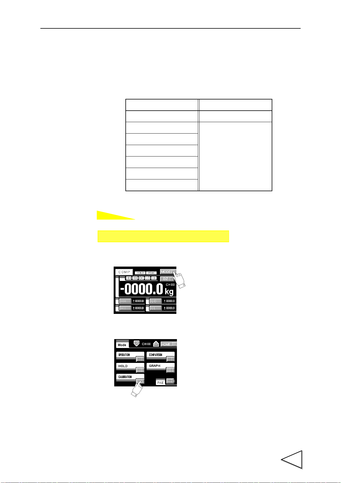
Calibration Protection
This call can be made by the following procedure.
1)Press the MODE button on the ordinary display screen.
2)The mode setting screen appears. Select the mode.
3)The setting function setting screen appears. Select the function.
8
Page 20

3. CONNECTION
(
Black
)
(
White)
(
Green)
AC
IN
L
N
F. G.
Check the wiring precisely before power source is turned on.
CAUTION
(
Red
)
(
Black)
DC IN
+
-
F. G.
Be aware that the voltage drops depending on the wire thickness and
length. Also, never input an AC power source. Doing so will cause a
failure.
CAUTION
3-1. Connection with Power Source Input Terminal
AC spec.
3.CONNECTION
Connect AC power code attached to the terminal.
Voltage input : AC100V - 240V Frequency : 50/ 60Hz
DC spec. (Depending on the request at the time of order)
Connect the positive (+) side of the power source to the red screw side of the terminal
block on the back of the F370, and its negative (-) side to the black screw side. The input
voltage is 12V - 24V DC.
9
Page 21

3.CONNECTION
(+EXC)
(-EXC)
(+SIG)
(-SIG)
(F.G or )
+IN
-OUT
-IN
+OUT
A1
B2
A2
B1
F370
(+EXC)
(-EXC)
(+SIG)
(-SIG)
+IN
-OUT
-IN
+OUT
A1
B2
A2
B1
F370
(F.G or )
3-2. Load Cell Connection
・4-wire sensor
・6-wire sensor
Short-circuit +EXC with +S and -EXC with -S for connecting a 6-wire strain-gage
sensor.
10
Page 22

3-3. SI/F Connection
Converter
Display
Printer
SI/F
B10
B11
← Inside Outside →
F370
The 2-wire serial interface has connective ability for coupling a UNIPULSE printer,
external display, etc.
The interface is nonpolarized and up to three external instruments may be connected.
A two-core parallel cable or a cabtyre cable may be used for connection.
3.CONNECTION
11
Page 23

3.CONNECTION
COM1
Spark Killer
Load
F370 Inside
Spark Killer
DC
Var isto r
Load
AC
Relay
Vex t
A3
Supply an external power source for a relay drive
Output Data Tr
0 OFF
1 ON
● Output Transistor Status
power source (Vext).
Power
Supply
Power
Supply
COM2
Push
Switch
Toggle
Switch
Relay
+12V
TTL Open Collector
(ON when IN is HI)
F370 Inside
A6
IN
IN
Open → OFF
Short → ON
- The external element is required to withstand Ic=10mA.
- Leakage from the external element is required to be
100μA or below.
3-4. External I/O Connection
3-4-1. External Output Connection
The external output circuit is operated through an open collector. A3 COM1 is the
common terminal. The open collector output capacity is 30mA and the withstand voltage
is up to 30V.
・Equivalent circuit
3-4-2. External Input Connection
12
A signal is inputted to the signal input circuit by short-circuiting or opening the input
terminal and the COM2 terminal. Short-circuiting is effected by means of a contact (such
as a relay or a switch) or a noncontact (such as a transistor or an open-collector TTL).
Page 24

3-4-3. Connecting to Cage Clamp Terminal Block
5 - 6mm
・Cable can be from 24 to 14AWG (0.2 to 2.5mm2)
・ It is not necessary to solder the cable wires or to fix a solderless terminal.
・If several cables to be inserted to the same hole,twist those cable wires
together and insert.
・If you connect a cable (a load cell, SI/F, external input and output),
please turn off and be sure to perform the power supply of a main part.
CAUTION
The output terminal D/A option and RS-485 option is using the cage clamp system
terminal stand. Please connect in the following procedure.
1.Strip the casing 0.2inch (6mm) on the cable to be connected.
2.Twist the bare wire to fit the terminal hole.
3.Insert the supplied screwdriver into the upper hole and lift upward.
3.CONNECTION
4.Insert the twisted wires into the lower hole.
5.Make sure cable is clamped securely and does not come out with a slight tug.
13
Page 25

4.CALIBRATION
F370
Strain gauge sensor
Rated output value(mV/V)
+
Indicated value
A data sheet is attached to a strain-gage sensor at the time of purchase.
The data sheet provides data including:
capacity load (in kg, t, etc.)
rated output voltage (in mV/V)
non-linearity, hysteresis,input resistance,output resistance and zero
balance.
Enter the capacity and the rated output value required for equivalent
input calibration into the F370.
4. CALIBRATION
Calibration is performed for matching the F370 to a strain-gage sensor. The following
two types of calibration are available for the F370.
◇ Equivalent Input Calibration
Calibration is performed without an actual load by entering the rated output value (mV/
V) and the capacity (to be indicated) of the strain-gage sensor by the keys. Calibration is
easily performed when no actual load is available.
For example, the gain is automatically determined by entering:
2.001mV/V (rated output) - 100.0kg (capacity)
as indicated for a load.
14
Page 26

◇ Actual Load Calibration
Actual
Strain gauge sensor
Indicated value
F370
load
Protection Release
Increment
Input Calibration
Calibration Protection
Decimal Place
Digital Offset
4-9.
4-7.
4-8.
4-5.
4-6.
4-9.
Zero Calibration
4-3.
Value Selection
4-10.
Calibration
Equivalent
Calibration
Apply an actual load to the strain-gage sensor and enter the actual load value by the keys
for calibration. Calibration is accurately performed with reductions in errors.
4-1. Equivalent Input Calibration Procedure
4.CALIBRATION
Follow the steps below to perform equivalent input calibration.
Release the calibration protection.
Set the calibration value No.
(This step may be omitted for use with only one
selection.)
Enter the minimum value of digital increments.
(This step may be omitted if there is no change.)
Determine the decimal point place of the indicated value.
(This step may be omitted if there is no change.)
Set the zero point of the strain-gage sensor in no-load
condition (with the sensor unloaded).
Enter the rated output value and reading of the strain-gage
sensor.
The calibrated value can be offset in advance.
(This step may be omitted if there is no change.)
Turn on the calibration protection for preventing
misoperation.
15
Page 27

4.CALIBRATION
Protection Release
Increment
Load Calibration
Calibration Protection
Decimal Place
Digital Offset
4-9.
4-7.
4-8.
4-4.
4-6.
4-9.
Zero Calibration
4-3.
Value Selection
4-10.
Calibration
Actual
Calibration
4-2. Actual Load Calibration Procedure
Follow the steps below to perform equivalent input calibration.
Release the calibration protection.
Set the calibration value No.
(This step may be omitted for use with only one
selection.)
Enter the minimum value of digital increments.
(This step may be omitted if there is no change.)
Determine the decimal point place of the indicated value.
(This step may be omitted if there is no change.)
Set the zero point of the strain-gage sensor in no-load
condition (with the sensor unloaded).
Enter the span (gain) point of the strain-gage sensor with a
load applied to the sensor.
The calibrated value can be offset in advance.
(This step may be omitted if there is no change.)
Turn on the calibration protection for preventing
misoperation.
16
Page 28

4-3. Zero Calibration
How to set
Setting call Page 1
→→
Calibration
Set the zero point in no-load condition.
1)Press the MODE button.
4.CALIBRATION
2)Press the CALIBRATION button.
3)Press the Zero Cal. button.
4)Press OK button after confirming no-load was applied to the sensor.
17
Page 29

4.CALIBRATION
How to set
Setting call Page 1
→→
Calibration
4-4. Actual Load Calibration
Set the actual load value under an actual load.
1)Press the MODE button.
2)Press the CALIBRATION button.
3)Press the Actual Cal. button.
4)Apply an actual load to the sensor, enter the actual load value by the numerical keys
and determine with the OK button.
18
Page 30

4-5. Equivalent Input Calibration
How to set
Setting call Page 1
→→
Calibration
Set the rated output value and reading of the sensor.
Rated output value: 0.000 - 3.000mV/V
Rated value: 00000 - 99999
1)Press the MODE button.
4.CALIBRATION
2)Press the CALIBRATION button.
3)Press the Equiv.Cal. button.
19
Page 31

4.CALIBRATION
4)Enter the rated output of the sensor by the numerical keys and determine with the OK
button. The decimal point is fixed.
5)Enter the rated value by the numerical keys and determine with the OK button.
20
Page 32
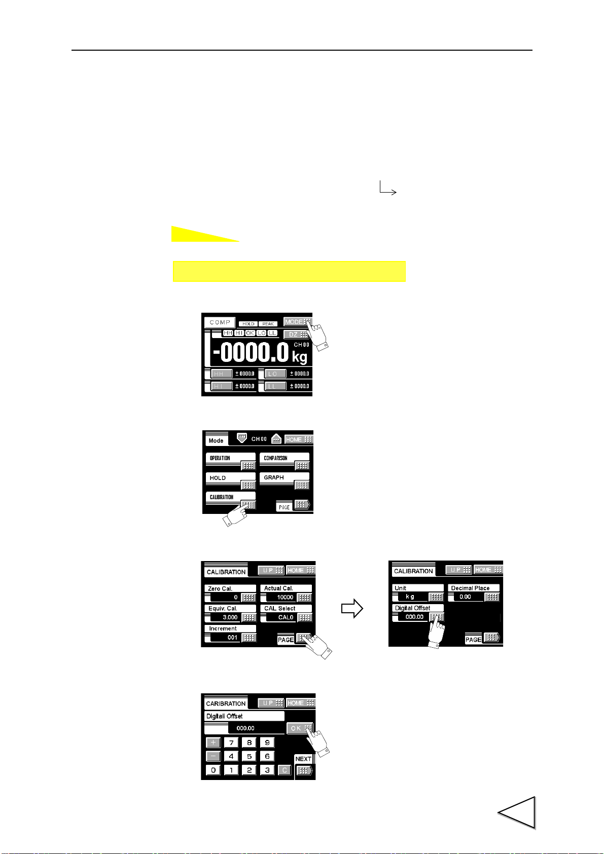
4-6. Digital Offset
How to set
- 99999 - 99999
Setting range:
Setting call Page 2
→→
Calibration
By using the digital offset function, the value obtained by subtracting the set value from
the indicated value is displayed.
This function is convenient when zero cannot be obtained with no load for some reason
or for offsetting.
(displayed value)=(actual indicated value)-(offset value)
1)Press the MODE button.
4.CALIBRATION
2)Press the CALIBRATION button.
3)Press the PAGE button to select the page and press the Digital Offset button.
4)Enter the digital offset value by the numerical keys and determine with the OK button.
21
Page 33
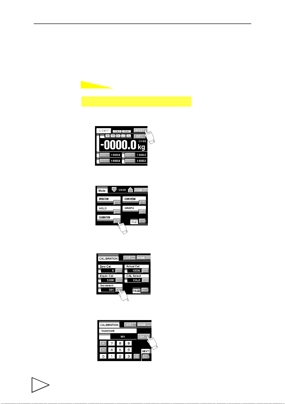
4.CALIBRATION
How to set
Setting call Page 1
→→
Calibration
4-7. Increment (This step may be omitted if there is no change.)
Set the increment of the indicated value.
Input range: 001 - 100
1)Press the MODE button.
2)Press the CALIBRATION button.
3)Press the INCREMENT button.
4)Enter the increment by the numerical keys and determine with the OK button.
22
Page 34
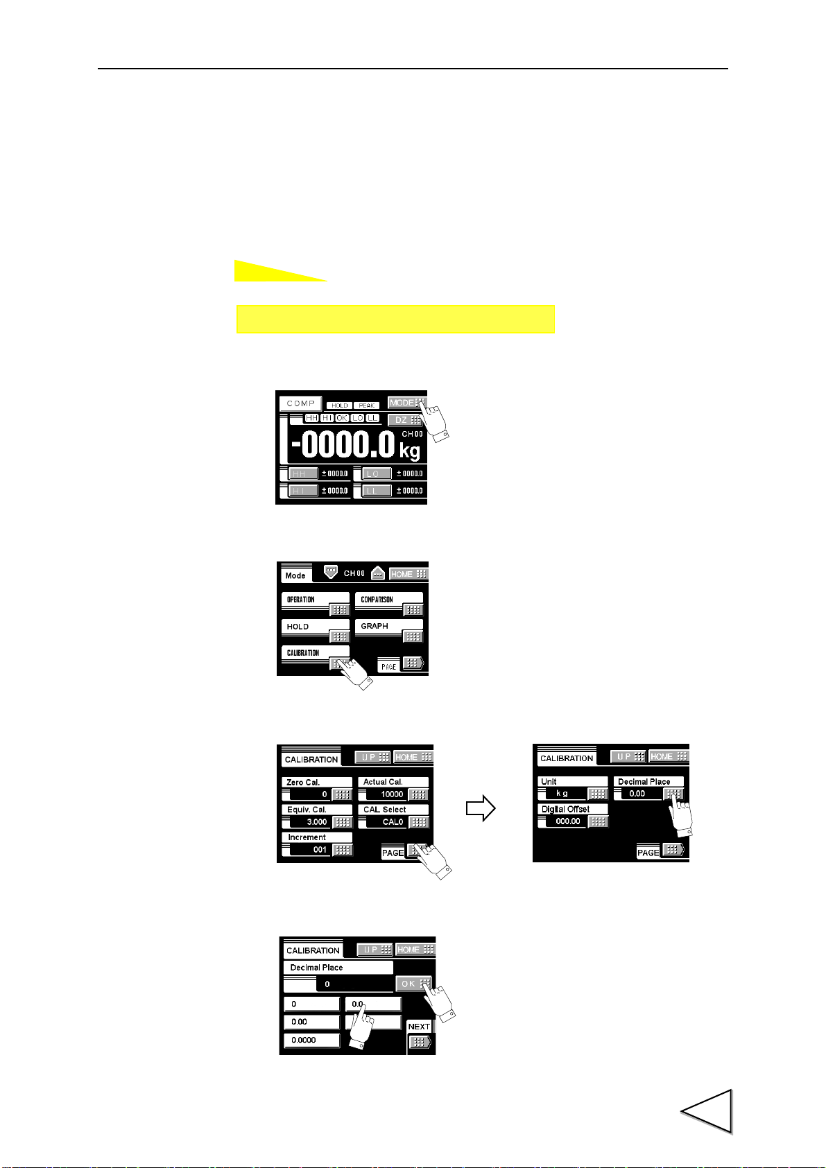
4-8. Decimal Place
How to set
Setting call Page 2
→→
Calibration
①
①
②
Set the decimal point place of the indicated value. Selection can be made from the
following.
1)Press the MODE button.
4.CALIBRATION
0, 0.0, 0.00, 0.000, 0.0000
2)Press the CALIBRATION button.
3)Press the PAGE button to select the page and press the DECIMAL PLACE button.
4)Select the decimal place and determine with the OK button.
23
Page 35
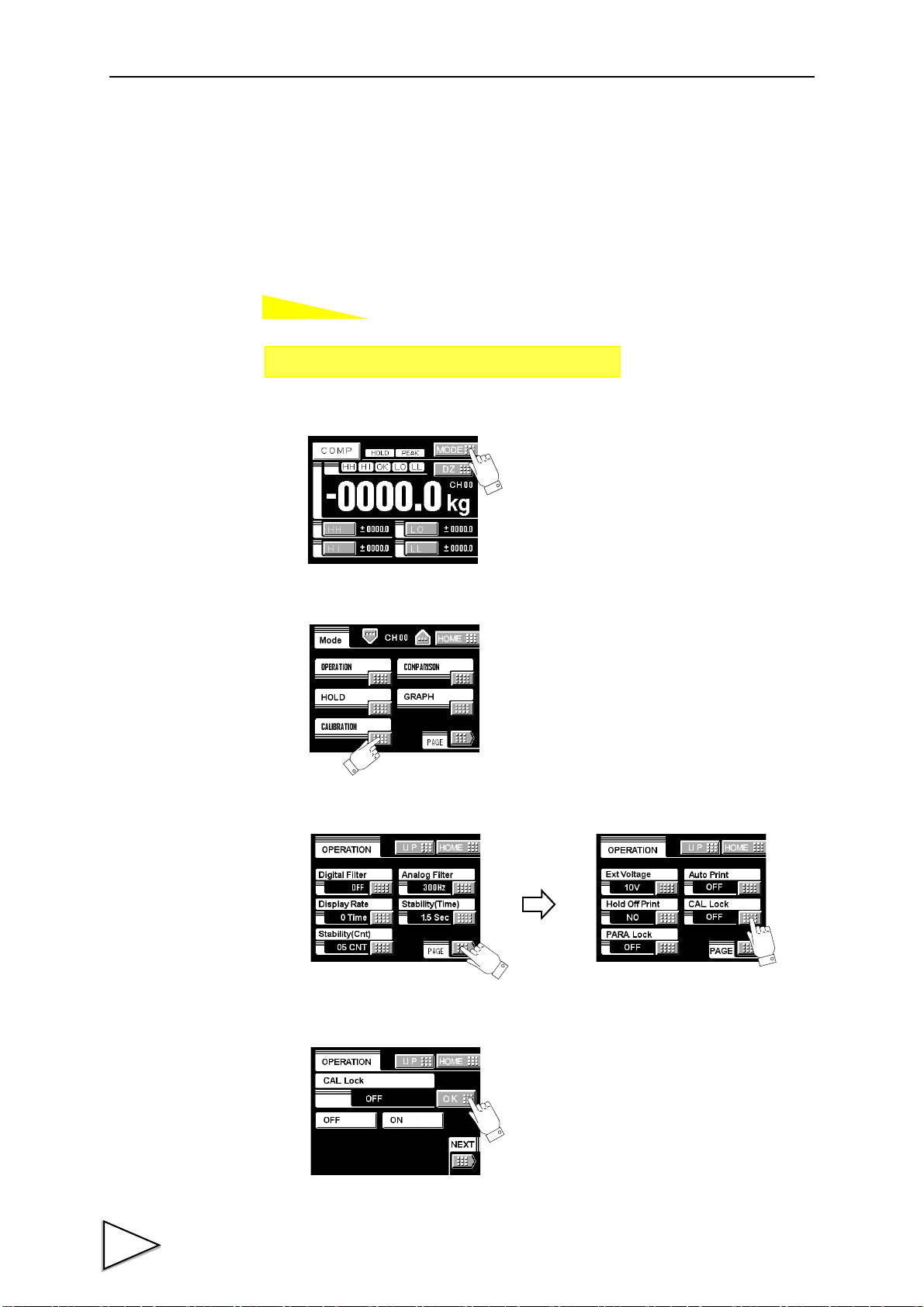
4.CALIBRATION
How to set
Setting call Page 3
→→
Calibration
4-9. Calibration Protection
Calibration-related set values can be protected so that they will not be changed by
misoperation. When Cal. Protect is ON, no change can be made while the alarm sounds.
ON: Protected
OFF: Unprotected
1)Press the MODE button.
2)Press the CALIBRATION button.
3)Press the PAGE button to select the page twice and press the Cal Lock button.
4)Select the decimal place and determine with the OK button.
24
Page 36
4-10. Calibration Value Selection
How to set
Setting call Page 1
→→
Calibration
By storing up to four calibration values in the memory, the desired calibration value can
be called to switch the indicated value. Setting values that can be switched are as
follows:
Calibration Mode Setting Operation Mode Setting
Zero Calibration Excitation Voltage
Actual Load Calibration
Equivalent Input Calibration
Minimum Slope
Unit
Decimal Place
Digital Offset
4.CALIBRATION
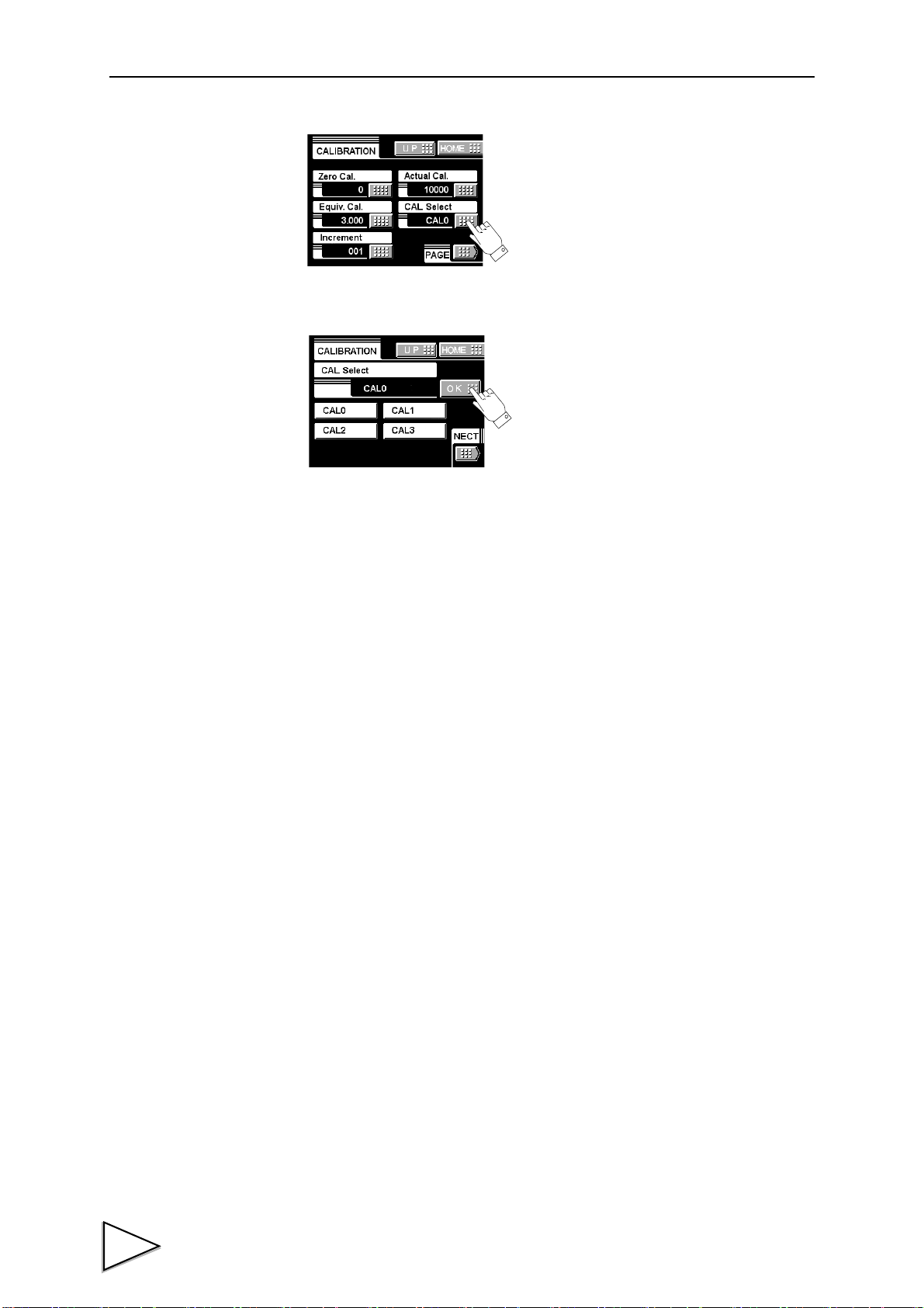
1)Press the MODE button.
2)Press the CALIBRATION button.
25
Page 37
4.CALIBRATION
3)Press the CAL. SELECT button.
4)Select the calibration value from 0 - 3 and determine with the OK button.
26
Page 38
4-11. Unit
How to set
Setting call Page 2
→→
Calibration
Scroll with the and buttons.
* A change of unit does not affect the indicated value (calibration value)
.
4.CALIBRATION
Set the unit of the load to be displayed. Selection can be made from the following.
2
None, kg, g, t, N, kN, Nm, N/m
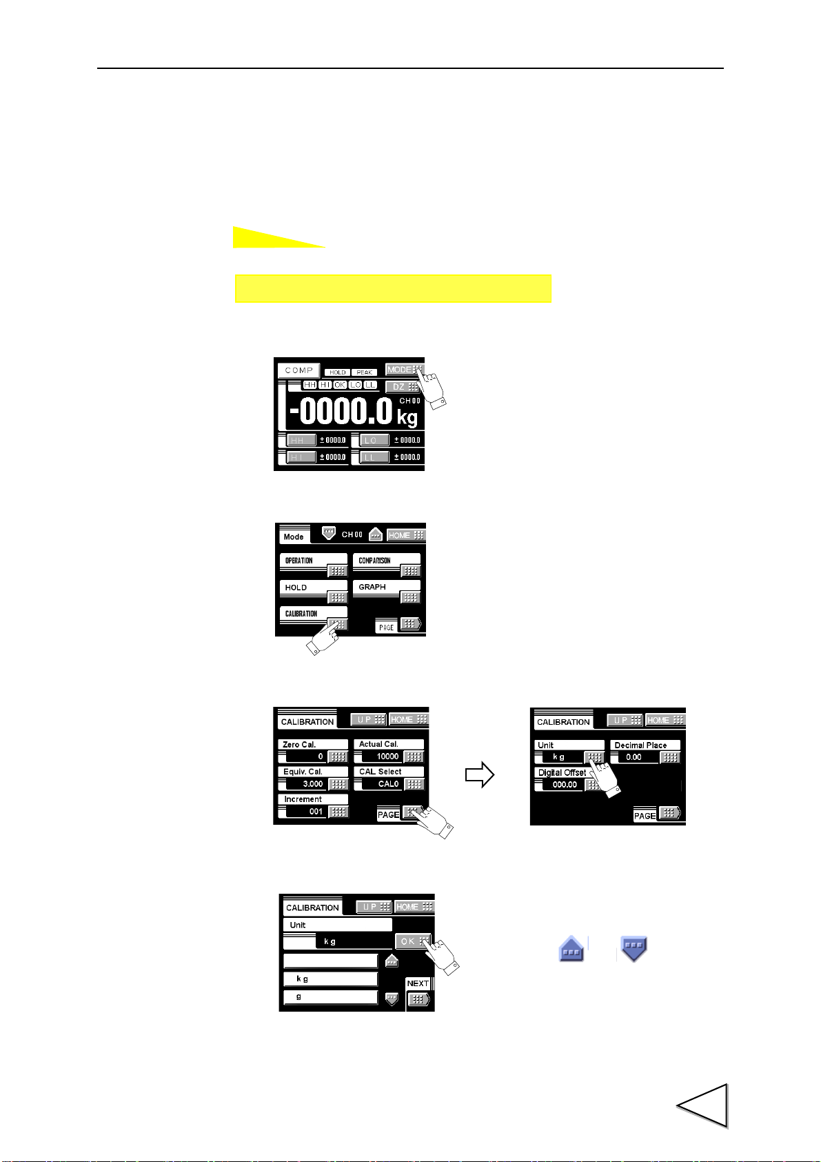
1)Press the MODE button.
, Pa, kPa, MPa, bar
2)Press the CALIBRATION button.
3)Press the PAGE button to select the page and press the UNIT button.
4)Select the unit and determine with the OK button.
27
Page 39

5.SETTING OF FUNCTIONS
OK
CANCEL
5. SETTING OF FUNCTIONS
5-1. Digital Zero
This function zeros the value currently indicated.
Digital Zero by key input
1) Press the DZ button on the ordinary display screen.
2) Digital Zero is activated by pressing OK button then indicated value becomes
zero. By pressing CANCEL The screen returns to the ordinary dis
play screen.
28
Page 40
Digital Zero conducted by External signal (D/Z input)
How to set
D/Z
OFF
ON
Keep on for 1.0 msec. or more.
In case of power interruption Digital Zero is released.
After recovering from power interruption, carry out the digital zero
again if necessary.
CAUTION
Setting call Page 1
→
→
Operation Setting
* See the section on About a
Setting Call page 8 .
Scroll button
Digital Zero activates in the moment when the connection of the external input
terminal D/Z on the rear panel and COM2 is switched from Open to Short-circuit
then the indicated value becomes Zero.
5.SETTING OF FUNCTIONS
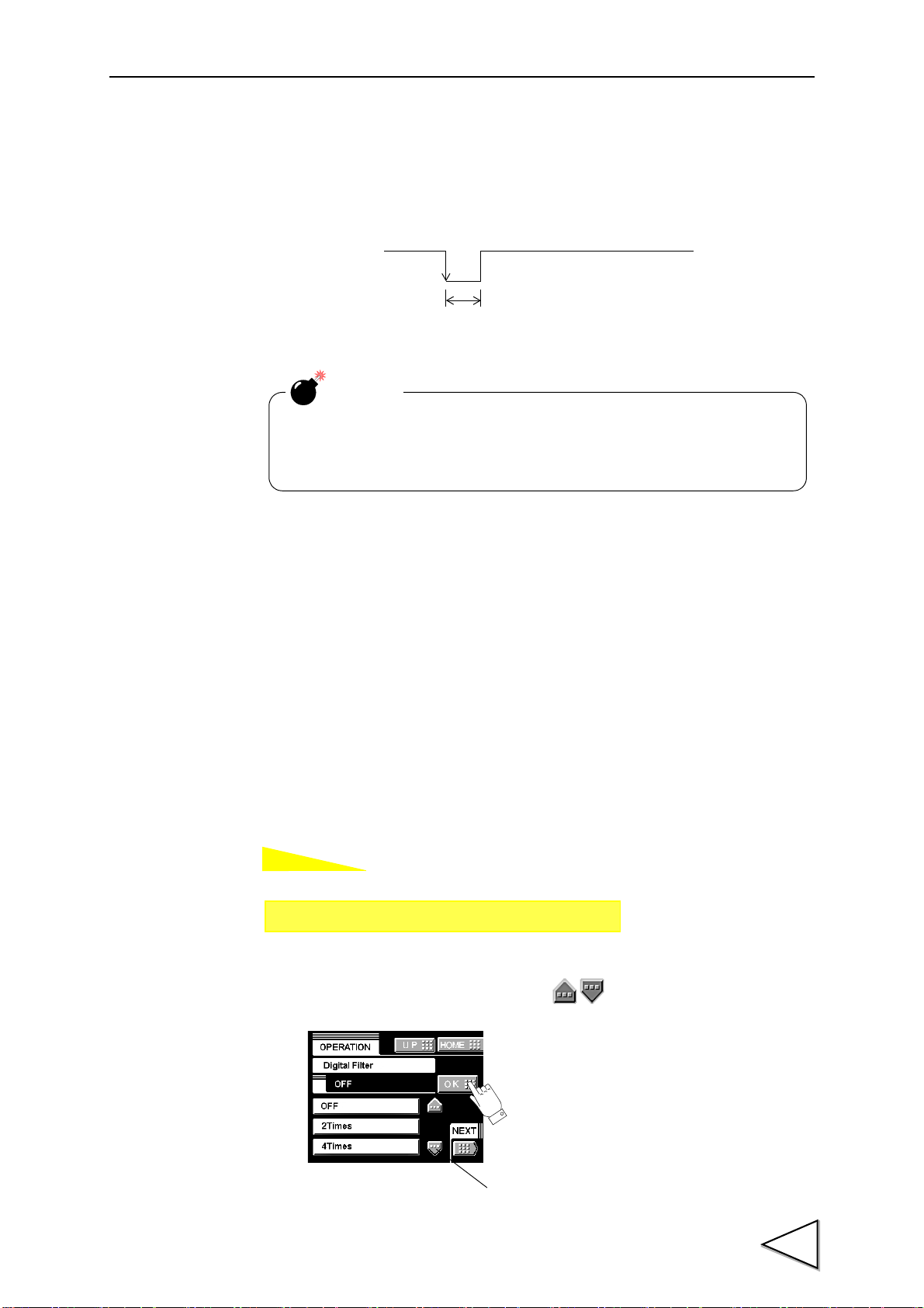
5-2. Digital Filter
The digital filter is a function for reducing drifts of the indicated value by means of a
moving average of data converted from analog to digital. The number of the moving
averages can be selected a range between 0 and 512.
With an increase in the number of filterings, the indicated value becomes more stable,but
the response to inputs becomes slower.
The value of a digital filter is scrolled with a button.
Number of settings:OFF, 2, 4, 8, 16, 32, 64, 128, 256, 512
29
Page 41

5.SETTING OF FUNCTIONS
How to set
How to set
Setting call Page 1
→
→
Operation Setting
Setting call Page 1
→
→
Operation Setting
5-3. Analog Filter
A low-pass filter is provided for filtering input signals from the strain-gage sensor and
canceling noise components.
The cut-off frequency can be selected in a range between 10Hz and 300Hz. With an
increase in the cut-off frequency, the response becomes faster, but noise components
may be indicated.
Cut-off frequency: 10Hz, 30Hz, 100Hz, 300Hz
5-4. Display Rate
Enter the rate of rewriting the display.
The display rate can be selected in a range between 1 and 10 times/sec. The internal
operation speed does not change.
30
Page 42

5-5. Stability
How to set
Set
Indicated Value
50msec
Time
Set Period
range
Setting call Page 1
→
→
Operation Setting
When the time is 0.0 sec. and the width is 00 markings, stability is not
detected. At this time, the stable-time digital filter is normally off.
Turning on/off the near zero function is closely related to the auto
print function and HI-LO limit comparison mode.
For details, see the sections on Auto Print page 34 and HI-LO Limit
Comparison Mode page 41.
CAUTION
5.SETTING OF FUNCTIONS
Enter the parameters to detect stability.
If the difference between the current indicated value and the 50-msec-previously
indicated value is less than the set count and the duration of the condition is more than
the set time, the indicated value is regarded to be stable.
When stability is detected, a digital filter (fixed 16 times) to control instability in weight
value is automatically inserted. This stable-time digital filter differs from the digital filter
setting in the operation mode.
Setting range
- MD (time): 0.1 - 9.9 sec.
- MD (width): 01 - 99
31
Page 43

5.SETTING OF FUNCTIONS
How to set
・When displacement of the zero point is within the set count of tracking
and it continues more than the set time, it is automatically made zero by
Zero Tracking function.
・The time (tracking delay) is set in the range of 0.1 - 9.9 sec., and the
band (tracking band) is set in the range of 01 to 99.
If the time is set at 0.0 sec. and the band at 00, the zero tracking function
does not work.
Boundary of zero track
DELAY
Indicated value
+COUNT
-COUNT
BAND
+
0
-
DELAY
Band=count × 2
From the point when it returned within the range,
counting will be resumed.
Since the zero track function works from the calibrated zero point of the
indicated value, it does not work if the indicated value is beyond the
track band. In such a case, obtain the zero point again by zero
calibration.
CAUTION
Setting call Page 2
→
→
Operation Setting
5-6. Zero Track
Gradual changes in the zero point due to drifts etc., are automatically tracked for
correction.
Setting range
ZT (time): 0.0 - 9.9 sec.
ZT (width): 00 - 99
32
Page 44

5-7. Contrast Adjustment
How to set
How to set
How to set
Setting call Page 2
→
→
Operation Setting
Setting call Page 2
→
→
Operation Setting
Setting call Page 3
→
→
Operation Setting
Adjust the contrast of the touch panel display.
Brightness can be adjusted by CONTRAST1.
Screen flickering can be adjusted by CONTRAST2.
5-8. Backlight
The backlight is turned off if no button operation is performed for the set time (minutes).
5.SETTING OF FUNCTIONS
The backlight is turned on by touching the panel. Setting 00 disables this function.
Setting range: 00 - 99 min.
5-9. Excitation Voltage
Select the bridge voltage to be supplied to the strain-gage sensor.
The bridge voltage is selectable from 10V, 5V and 2.5V.
Be sure to perform calibration after changing this setting.
33
Page 45

5.SETTING OF FUNCTIONS
How to set
Setting call Page 3
→→
Calibration
Indicated Value
Near Zero
0
Stable
Near Zero
ON
ON
ON
ON
OFF
OFF
OFF
Autmatic
↑
Hold
1.5Seconds
Time
ON
Hold function……
・Indicatid Value
・SI/F
・Compariosn
+
Sensor input value
Output signal
Printing
5-10. Auto Print
The indicated value is automatically printed to the UNIPULSE printer coupled with the
F370 through the SI/F. A print is made when the indicated value is stable. (Set the
stability parameters by the stability operation.)
When Near Zero is OFF, Indicated value is held until Near Zero turns ON after Stability
turned ON.
(Hold will be released when 1.5 sec. is passed after Near Zero is ON.)
・Operation of the indicated value hold function
34
Page 46

5.SETTING OF FUNCTIONS
Near Zero
0
Time
Stable
Near Zero
ON
ON
ON
ON
OFF
OFF
OFF
Autmatic
↑
Hold
1.5Seconds
ON
-
Indicated
Sensor input value
Printing
Va l ue
Auto Print is not performed under the following conditions.
・Motion Detect
Time: 0.0 sec. Width: 0.0 of divisions is set.
・Print while hold is released.
When Print is set.
・Hold Mode
When any items except Tracking is selected.
35
Page 47

5.SETTING OF FUNCTIONS
How to set
How to set
Setting call Page 3
→→
Calibration
Setting call Page 3
→→
Calibration
For the parameters which are protected by parameter protection,
see the section on SETTING ITEM CHART page 113.
5-11. Hold Off Print
At hold-off time, the held value is automatically printed to the UNIPULSE printer
coupled with the F370 through the SI/F.
(The hold is released by the T/H signal off timing when the period setting is all interval
in various hold modes by hold functions, and by the T/H signal of timing when other
periods are set.)
5-12. Parameter Protection
Parameters are protected from being changed by misoperation.
36
Page 48

6. COMPARISON FUNCTIONS
Time
Indicated value
HI Limit
LO Limit
HI
LO
OFF
ON
OFF
ON
HI-HI Limit
LL Limit
OFF
ON
OFF
ON
HH
LL
OFF
ON
OK
Va lu e
Va lu e
Va lu e
Va lu e
By the comparison function, the HI limit and LO limit values are set, and when the
indicated value exceeds the HI limit, the HI output is turned on, and when the indicated
value falls below the LO limit, the LO output is turned on. Also, HI-HI limit and LO-LO
limit values may be set outside the HI-LO limit comparison. When the indicated value
exceeds the HI-HI limit, the HH output is turned on, and when the indicated value falls
below the LO-LO limit, the LL output is turned on. When the HI, HH, LO and LL
outputs are all off, the OK output is turned on.
<HI/LO output conditions>
HI: indicated value > HI limit value
LO: indicated value < LO limit value
<HH/LL output conditions>
HH: indicated value > HI-HI limit value
LL: indicated value < LO-LO limit value
6.COMPARISON FUNCTIONS
<OK output conditions>
OK: All conditions of HH, HI, LO and LL are off.
37
Page 49
6.COMPARISON FUNCTIONS
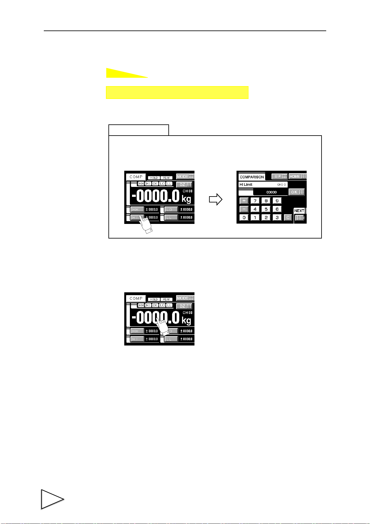
How to set
Setting call Page 1
→→
Comparison setting
Press any of the HI-HI, HI, LO and LO-LO buttons at the bottom of the indicated
value display screen to go direct to the entry screen.
Simple setting call
6-1. HI Limit/LO Limit/HI-HI Limit/LO-LO Limit
About the indicated value display color
The display color can be changed by pressing the indicated value display section. Every
time it is pressed, State 1 and State 2 are changed.
・State 1
The indicated value display color is fixed (yellow).
・State 2
The indicated value display color changes following the comparison status.
OK: green
HI, LO: yellow
38
HH, LL: red
Page 50

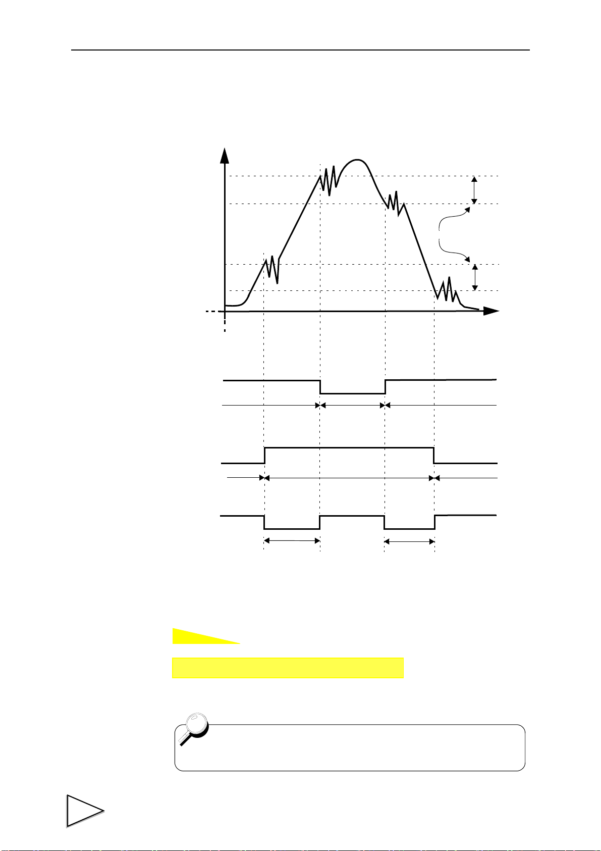
6-2. Hysteresis
The hysteresis value may be determined so as to allow a margin for timing the turning off
of the HI-LO limit comparison. Normally, it is turned on when the indicated value
exceeds the HI limit and is turned off when the indicated value falls below it. However,
by setting the hysteresis, it is turned off when the indicated value falls below the HI limit
further lowered by the hysteresis value.
This function is effective to prevent chattering in such a case where signals fluctuate
(vibrate) subtly.
〈Comparison conditions〉
6.COMPARISON FUNCTIONS
- HI limit
ON condition: indicated value>HI limit value
OFF condition: indicated value<=(HI limit value-hysteresis value)
- LO limit
ON condition: indicated value<LO limit value
OFF condition: indicated value>=(LO limit value+hysteresis value)
- HI-HI limit
ON condition: indicated value>HI-HI limit value
OFF condition: indicated value<=(HI-HI limit value-hysteresis value)
- LO-LO limit
ON condition: indicated value<LO-LO limit value
OFF condition: indicated value>=(LO-LO limit value+hysteresis value)
39
Page 51
6.COMPARISON FUNCTIONS
How to set
HI Limit
LO Limit
+
0
Hysteresis Range
Time
HI Output
HI Status Display
LO Output
LO Status Display
OK Status Display
Output ON
Status ON
Output OFF
Status OFF
Status ON Status ON
Output ON
Status ON
Output ON
Status ON
-
Output OFF
Status OFF
Output OFF
Status OFF
Indicated Value
OK Output
( Exsample : HI Output and LO Output and OK Output )
Value
Value
Setting call Page 1
→→
Comparison setting
Hysteresis setting value is common to all HI limit value.
・ Hysteresis operation
40
Page 52

6-3. Near Zero
How to set
How to set
Turning on/off the near zero function is closely related to the auto print
function and HI-LO limit comparison.
For details, see the sections on HI-LO Limit Comparison Mode page 41
and Auto Print page 34.
Setting call Page 2
→→
Comparison setting
Setting call Page 2
→→
Comparison setting
By this function, it is detected that the indicated value is near zero.
6.COMPARISON FUNCTIONS
Near-zero ON: indicated value <=near zero set value
Near-zero OFF: indicated value > near zero set value
Setting range: 00000 - 99999
6-4. HI-LO Limit Comparison Mode
Set the operating condition of HI-LO limit comparison. Select the condition from the
following.
Continuous :HI-LO limit comparison is performed continuously.
MD :HI-LO limit comparison is performed when the indicated value
is stable. Set the stability parameters by the stability operation.
NZ :HI-LO limit comparison is performed when the indicated value
is not near zero.
Set the near zero parameters by the near zero operation.
MD+NZ :HI-LO limit comparison is performed when the indicated value
is stable and not near zero.
41
Page 53
6.COMPARISON FUNCTIONS
How to set
The HI limit output is turned on when the indicated value becomes
larger than the set value.
The LO limit output is turned on when the indicated value becomes
smaller than the set value.
Caution
Even if any mode other than MODE 2 is selected, the name of
each setting does not change. Only the operation differs.
Setting call Page 2
→→
Comparison setting
6-5. HI-LO Limit Output Mode
The number of HI-LO limits can be changed.
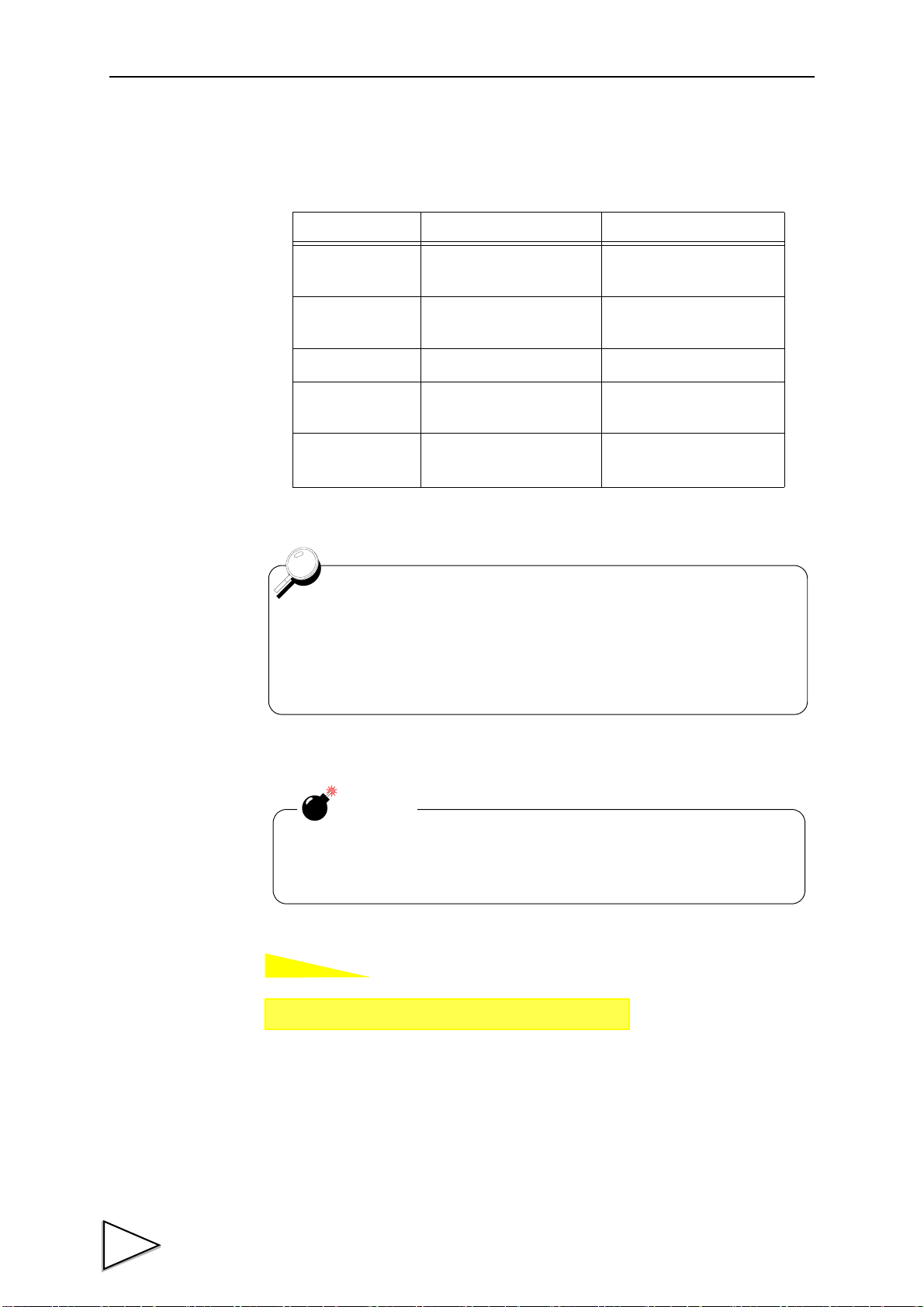
Mode HI Limit Operation LO Limit Operation
Mode 0
Mode 1
Mode 2
Mode 3 HI-HI Limit
Mode 4 None
HI-HI Limit,HI Limit,
LO Limit,LO-LO Limit
HI-HI Limit,HI Limit,
LO Limit
HI-HI Limit,HI Limit LO Limit,LO-LO Limit
None
LO-LO Limit
HI Limit,LO Limit,
LO-LO Limit
HI-HI Limit,HI Limit,
LO Limit,LO-LO Limit
42
Page 54
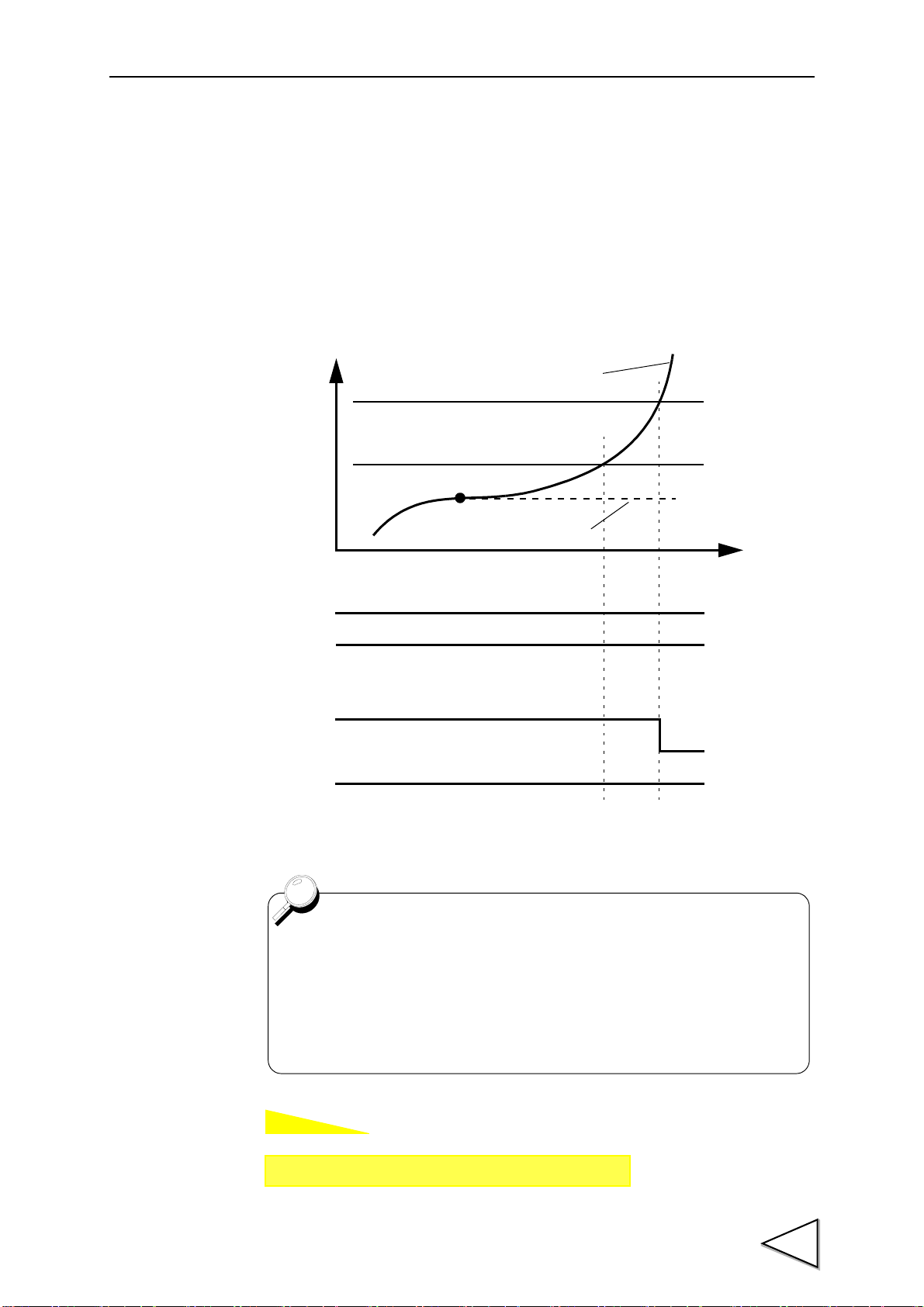
6-6. Alarm Mode
How to set
Hold values
HI-HI Limit (HH)
HI Limit (HI)
Real-time values
HH
HI
OFF
ON
OFF
HH
HI
OFF
Alarm mode unavailable
Alarm mode available
When the comparison output mode is “mode 0: HI limit operation for
all of HI-HI limit/HI limit/LO limit/ LO-LO limit”, the alarm mode
operation can only be performed with the HI-HI limit.
In a like manner, when the mode is “mode 4: LO limit operation for all
of HI-HI limit/HI limit/LO limit/LO-LO limit”, the alarm mode operation
can only be performed with the low-low limit.
Setting call Page 2
→→
Comparison setting
The comparison target of the HI-HI limit and LO-LO limit set values can be changed
from “hold value” to “real-time value”. By this function, whether or not the indicated
value becomes abnormal during hold can be monitored.
Unavailable : Comparison operation is performed with hold values.
Available : Comparison operation is performed with real-time values.
6.COMPARISON FUNCTIONS
43
Page 55

7.HOLD FUNCTIONS
How to set
Setting call Page 1
→
→
Hold
7. HOLD FUNCTIONS
By the hold function including sample hold, peak hold, valley hold, peak-to-peak hold,
relative maximum and minimum hold and inflection point hold, a specific point in a
waveform is taken out for HI-LO limit comparison.
The operation of each hold will be described in detail.
7-1. Hold Setting --- common ---
7-1-1. Hold Mode
The F370 includes nine hold modes as shown in the table below.
In the peak, valley, peak-to-peak and mean value modes, period setting is required.
Select all period, external signal, time, or time with trigger.
If you do not use any hold function, be sure to set the hold mode to tracking. (In tracking
condition, hold operation is not performed but input values are always displayed.)
HOLD MODE HOLD PERIOD SETTING
Tracking None
Sample None
Peak
Valley
P-P
Relative maximum
Relative minimum
Inflection Point
Mean value Required
Required
None
There is a section setup.
・ All Period
・ External Signal
・ Time
・ Time with trigger
44
Page 56
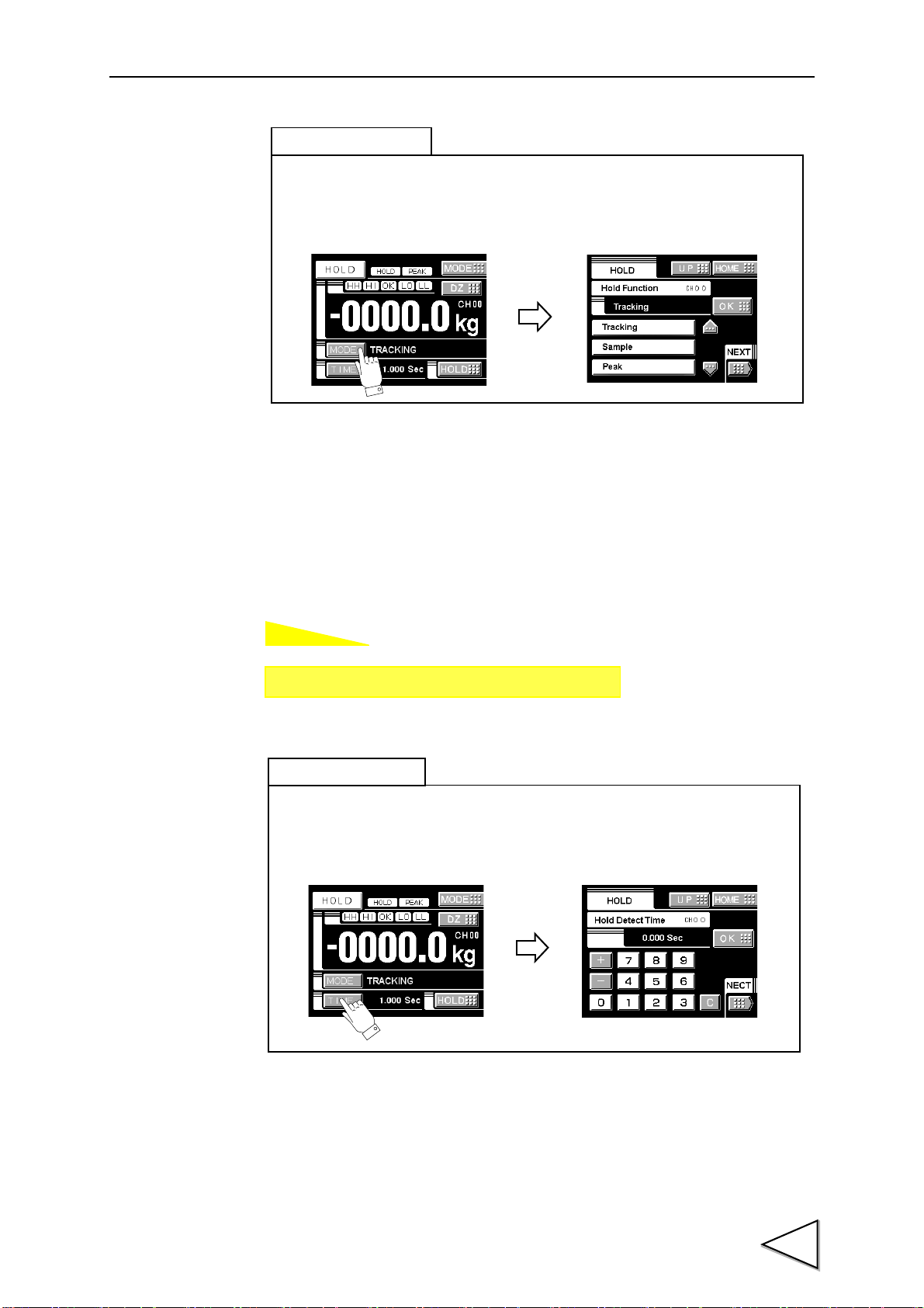
7-1-2. Hold Detection Time
How to set
Press the MODE button at the bottom of the indicated value display screen
to go direct to the hold mode entry screen.
Simple setting call
Setting call Page 1
→
→
Hold
Press the TIME button at the bottom of the indicated value display screen
to go direct to the hold detection time entry screen.
Simple setting call
7.HOLD FUNCTIONS
If you set the hold period setting in the hold function setting to Time or Time with
Trigger, set the time.
Setting range: 0.001 - 9.999 sec.
45
Page 57
7.HOLD FUNCTIONS
How to set
How to set
Setting call Page 1
→
→
Hold
In each hold mode of relative maximum/relative minimum/inflection
point, if the auto start level is set at 99999, the hold operation starts
only with the period signal H/M without performing level detection.
The actual hold point
t
w
When the hold point shift is set at 8,
the data eight pieces before
the actual hold point is held.
Caution
・This does not work for other holds.
・The retroactive sampling data is held irrespective of the hold
period. If the set numerical value is too large, point(s) out of the
period may be held.
Setting call Page 2
→
→
Hold
7-1-3. Auto Start Level
If you select the time specified period mode with trigger, or relative maximum, relative
minimum or inflection point hold in the hold mode setting, set the start level.
Setting range: -99999 - 99999
7-1-4. Hold Point Shift
In the “sample hold” and “inflection point hold”, the sampling data is held retroactively
by the numerical value set under hold point shift.
Setting range: -99999 - 99999
46
Page 58

7.HOLD FUNCTIONS
A
B
O
P
Q
2X
X
1.5X 3X
True relative maximum
True relative minimum
Relative
A
X
B
minimum
Relative
maximum
Maximum
Minimum
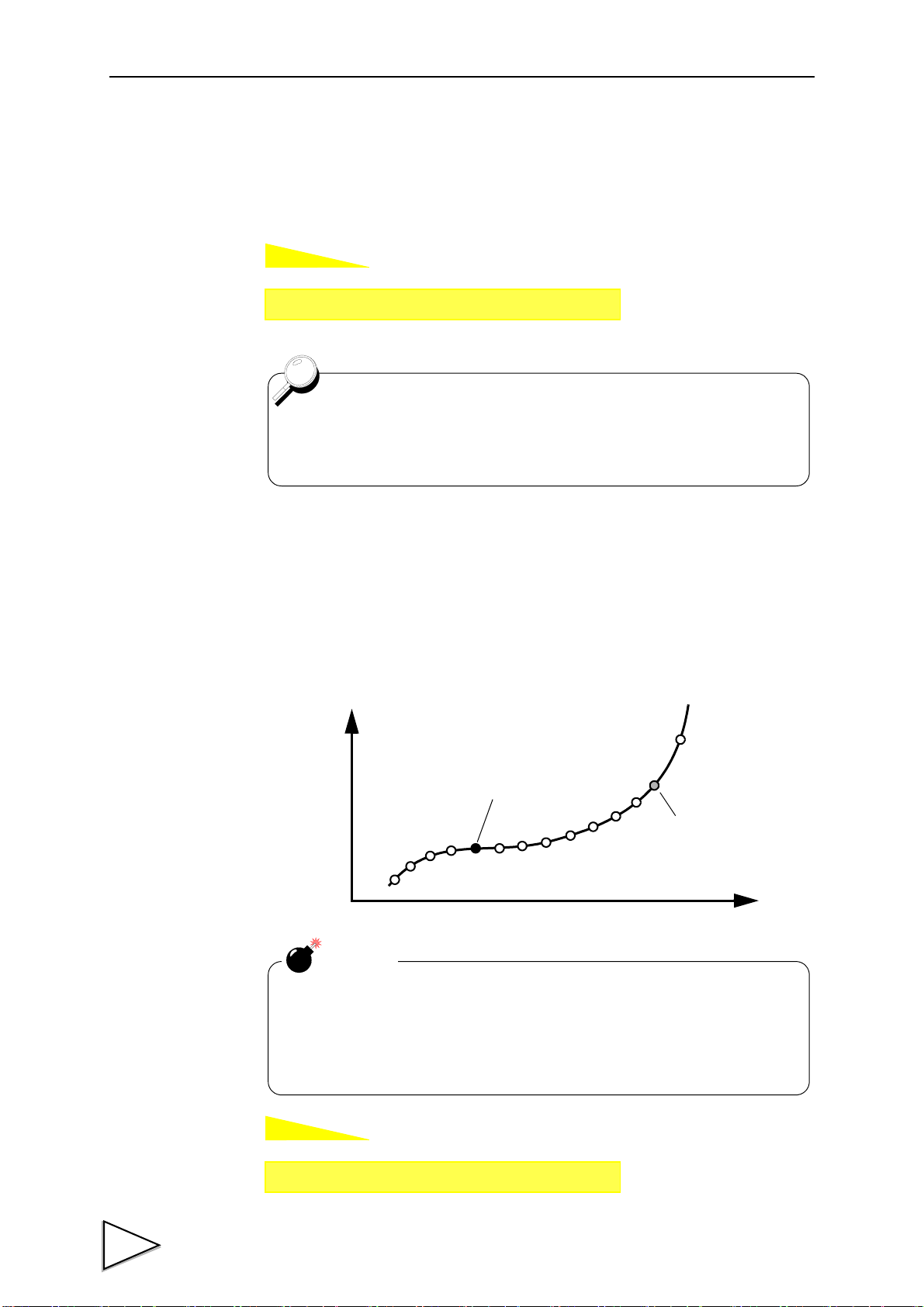
7-2. Hold Setting --- relative maximum and relative minimum ---
If you select the relative maximum and relative minimum hold in the hold function
setting, set the relative maximum and relative minimum value detection parameters
"minimum count" and "valley detection level".
Set referring to the principle of operation only when the value cannot be held
successfully with the factory settings or when further adjustments are required.
Detection of the relative maximum value and relative minimum value
The logic of detecting the relative maximum value and relative minimum value is given
below.
First, when difference X between point
A and point B is larger than the
minimum count, point A is judged to be
the relative maximum value and point B
is judged to be the relative minimum
value.
When difference X between detected
relative maximum value A and relative
minimum value B exceeds the
predetermined detection levels (1.5, 2
and 3 times), A is displayed in the
maximum value hold mode at respective
points O, P and Q and the value is held.
If the minimum count is too small, when
the waveform includes noise as shown
on the left-hand side, the noise is
regarded as the relative maximum value
or relative minimum value and a correct
value may not be held. In such a case,
set the minimum count somewhat large.
47
Page 59

7.HOLD FUNCTIONS
How to set
How to set
Setting call Page 1
→
→
Hold
Setting call Page 1
→
→
Hold
7-2-1. Minimum Count
Setting range: 0001 - 9999
7-2-2. Valley Detection Level
Level: 1/4, 1/2, 3/4, 1, 1.25, 1.5, 2, 3 times
48
Page 60

7-3. Hold Setting --- inflection point ---
D
C
C
AB
a
Input Signal
A : IntervalA
B : IntervalB
D : The amount of change
Inflection point
Held as an inflection point if
D > inflection judgment value.
If you select the inflection point hold in the hold function setting, set the inflection point
detection parameters "minimum slope", "interval A" and "interval B".
Set referring to the principle of operation only when the value cannot be held
successfully with the factory settings or when further adjustments are required.
Detection of the inflection point
The logic of detecting the inflection point is given below.
Assuming that the remainder obtained by subtracting the amount of change C of the
indicated value over interval A from the amount of change of the indicated value over
interval B is D, when the amount of change D exceeds the inflection point judgment
value, point a is held as an inflection point.
7.HOLD FUNCTIONS
If there are two or more inflection points in the hold period, the point having a larger
change is held.
The inflection point is normally detected by A=B, but it may easily be detected with
A<B where the slope is gradual.
49
Page 61

7.HOLD FUNCTIONS
How to set
How to set
Setting call Page 2
→
→
Hold
Setting call Page 2
→
→
Hold
The interval setting is the number of samplings. Since the F370's
sampling speed is 2000 times/sec., one sampling is 0.5msec.
Therefore, setting of the interval at 100 means setting of 50msec.
Load change time
True inflection
point
Inflection
point
7-3-1. Minimum Slope
Setting range: 00001 - 99999
7-3-2. Interval A and Interval B
Setting range:
- Interval A+Interval B ≦ 1000
- 10 ≦ Interval A(B) ≦ 990
Caution regarding inflection point hold
50
If the detection interval A and B are set
too short, fine load changes may be
detected as shown in the illustration on
the left-hand side, so that a correct value
cannot be held.
In this case, set the detection interval B
large enough to bring it as close to the
load change time as possible, and also
set the inflection point judgment value
large according to the amount of change
at that time, so that the inflection point
is held at a correct position.
Page 62

Example of inflection point hold setting
100
20
10
0
100msecA100msec
B
D = 80
C = 10
①
②
● Example of ideal waveform setting
① Set the load change time (between the inflection point and when the change stops) to
interval B.
In the example, it is set to 200 since it is 100 msec.
7.HOLD FUNCTIONS
② Set the same value as interval B to interval A.
③ Set load D obtained by subtracting load C changing with interval A from the load
changing with interval B to the inflection point judgment value.
In the example, set load change D=80 obtained by subtracting load C=10 changing
with A from load 90 changing with B to the inflection point judgment value.
However, since an inflection point is not judged until load change D exceeds the
inflection point judgment value, actually set the inflection point judgment value a
slightly smaller than D.
● If the inflection point cannot be located successfully
① When holding above the inflection point and
moving downward
1) It is considered that the inflection point
judgment value is small with respect to load
change D. Set the inflection point judgment
value larger.
2) If lowering is insufficient in 1), increase
interval A.
② When holding below the inflection point and
Shorten interval B and decrease the inflection point judgment value.
moving upward Interval B is too long and the
inflection point judgment value is too large.
51
Page 63

7.HOLD FUNCTIONS
How to set
Setting call Page 2
→
→
Hold
About the maximum mean value detection time
Although the detection period is specified by the H/M signal, etc.,
detection cannot be carried out exceeding the maximum mean value
detection time set according to the mean value sampling count. If the
maximum mean value detection time is exceeded, detection ends
automatically, when the mean value is held.
7-4. Hold Setting --- mean value ---
7-4-1. Mean Value Sampling Count
If the mean value sampling count is set at 2 or more in the mean value hold, the
representative value of the sampling values by the set count (mean value by the count) is
adopted as the sampling data used for mean value calculation.
The maximum mean value detection time with the setting “1” is 5 sec., but the mean
value detection time can be extended by this setting.
Maximum mean value detection time
where the number of updates of the mean value will decrease.
= Mean value sampling count × 5 [sec.],
Number of updates of the mean value
= 2000 / Mean value sampling count [times/sec.]
Setting range: 1 - 999Times
52
Page 64
7-5. Hold Operation
Indicated Value
t2
t3
t1
Sensor Input Value
Detection・Hold Period
Decide
t
+
T/H
HI-LO Limit
Judging Output
H/E
OFF
ON
OFF
ON
OFF
ON
HOLD
OFF
ON
Button
HOLD
Status Display
Status Display
ONBlink Blink
OFF
PEAK
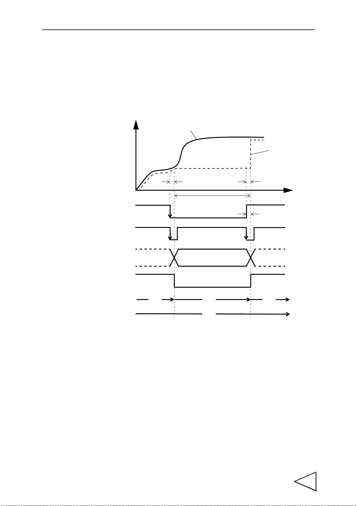
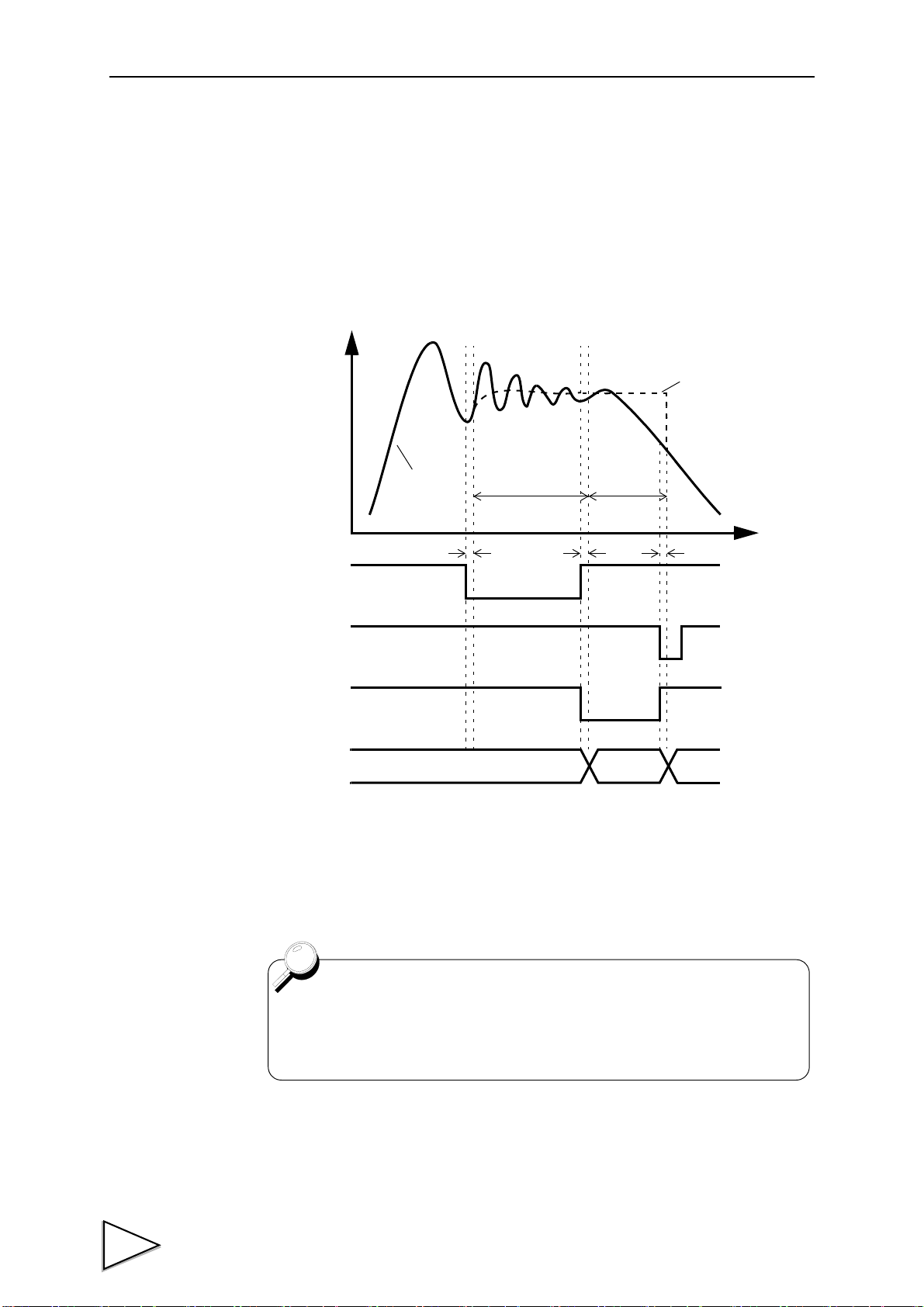
7-5-1. Sample Hold
When the T/H signal is inputted, a desired point is held, and the H/E output is turned on.
Hold of the value continues as long as the T/H signal is on.
7.HOLD FUNCTIONS
t1: A delay time between the instant when the T/H signal is inputted and the instant
t2:A delay time between the instant when the T/H signal is released and the instant
t3:A minimum reset signal width required for releasing the hold
when the indicated value is held
1.0ms (max.)
when the indicated value returns to tracking
1.0ms (max.)
1.0ms (min.)
53
Page 65
7.HOLD FUNCTIONS
Indicated Value
t2
t3
Sensor Input Value
Detection
t
+
T/H
HI-LO Limit
Judging Output
H/E
Detection
t1t2t1
t3
Note: During the undetermined period, the judging output varies with
fluctuations in the input waveform. However, the H/E output
remains on during the undetermined period. Read the judging
result when the indicated value becomes stable (immediately
before the T/H signal rises).
OFF
ON
OFF
ON
OFF
ON
OFF
ON
Status Display
PEAK
Status Display
ON
Blink Blink
OFF ON
OFF
OFF
OFF
OFF
OFF
HOLD
Button
Undetermind
Period(Note)
Undetermind
Period(Note)
Hold Period
Hold Period
HOLD
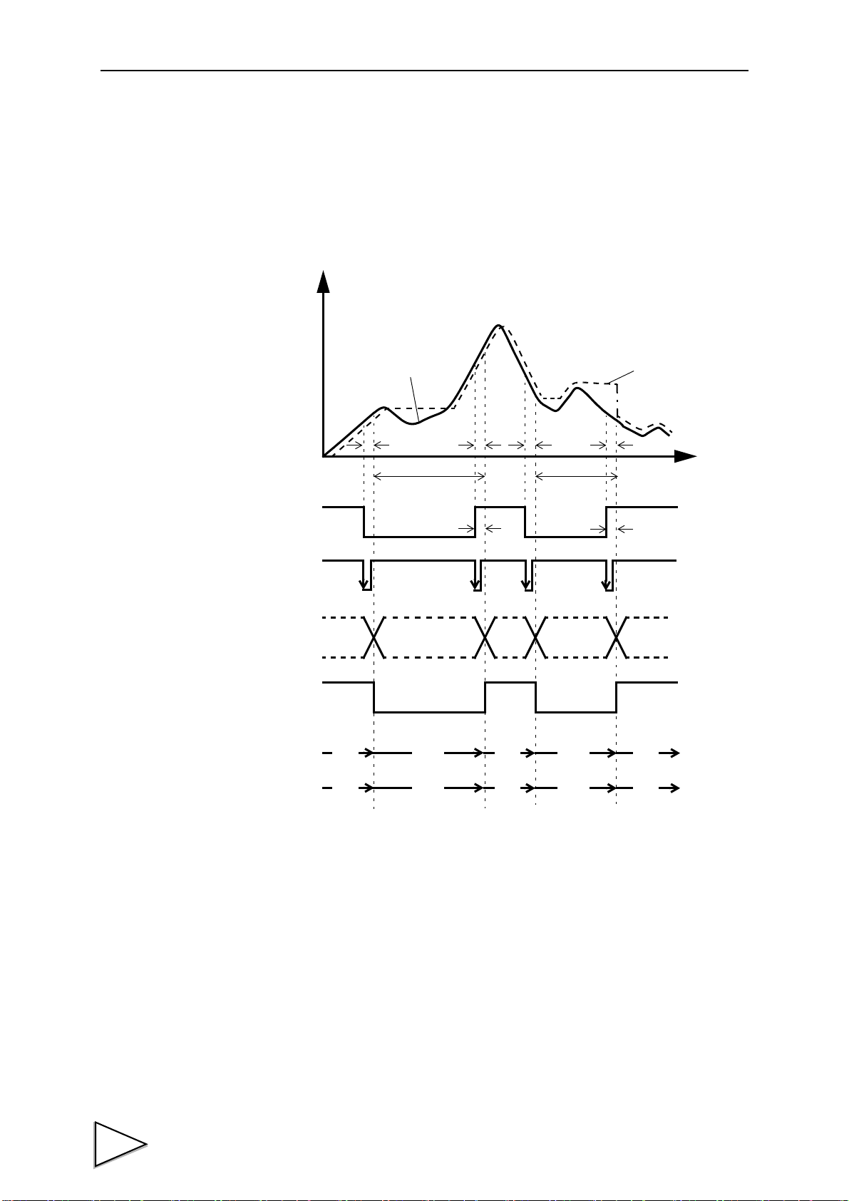
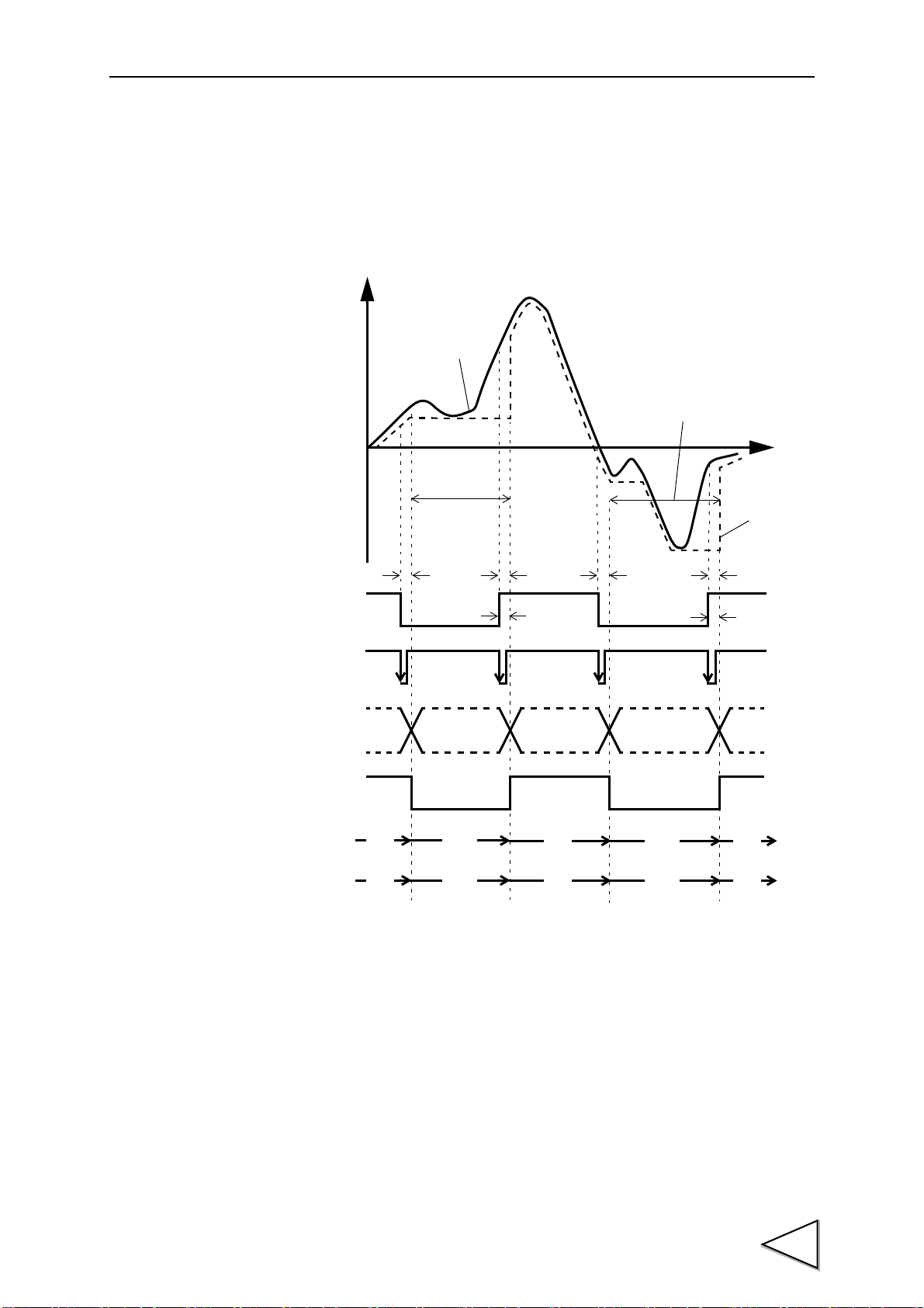
7-5-2. Peak Hold
The maximum value (peak) in the positive direction of the specified period is held.
The period is specified by the setting of “all period”, “external signal”, “time”, or “time
with trigger”.
(Example) All Period Peak Hold
t1: A delay time between the instant when the T/H signal is inputted and the instant
when the indicated value is held
1.0ms (max.)
t2: A delay time between the instant when the T/H signal is released and the instant
when the indicated value returns to tracking
1.0ms (max.)
t3:A minimum reset signal width required for releasing the hold
1.0ms (min.)
54
Page 66
7-5-3. Valley Hold
Indicated Value
t2
t3
Sensor Input Value
Detection
t
+
T/H
HI-LO Limit
Judging Output
H/E
Detection・Hold Period
t1t2t1
t3
Note: During the undetermined period, the judging output varies with
fluctuations in the input waveform. However, the H/E output
remains on during the undetermined period. Read the judging
result when the indicated value becomes stable (immediately
before the T/H signal rises).
OFF
ON
OFF
ON
OFF
ON
OFF
ON
HOLD
Status Display
PEAK
Status Display
ON
Blink Blink
OFF ON
OFF
OFF
OFF
OFF
OFF
HOLD
Button
Undetermind
Period(Note)
Undetermind
Period(Note)
Hold Period
The maximum value (valley) in the negative direction of the specified period is held.
The period is specified by the setting of “all period”, “external signal”, “time”, or “time
with trigger”.
(Example) All Period Valley Hold
7.HOLD FUNCTIONS
t1: A delay time between the instant when the T/H signal is inputted and the instant
when the indicated value is held
1.0ms (max.)
t2: A delay time between the instant when the T/H signal is released and the instant
when the indicated value returns to tracking
1.0ms (max.)
t3:A minimum reset signal width required for releasing the hold
1.0ms (min.)
55
Page 67
7.HOLD FUNCTIONS
Indicated Value
Sensor Input Value
Detection・Hold Period
Undetermind
t
+
T/H
HI-LO Limit
Judging Output
H/E
t2
t1
t3
Standard Line
(Hold Section Only)
Indicated Value = 0
Indicated Value=0
OFF
ON
OFF
ON
OFF
ON
HOLD
OFF
ON
Button
HOLD
Status Display
PEAK
Status Display
ON
Blink
OFF
OFF
OFF
OFF
Period(Note)
Note: During the undetermined period, the judging output varies with fluctuations in the
input waveform. However, the H/E output remains on during the undetermined
period. Read the judging result when the indicated value becomes stable
(immediately before the T/H signal rises).
7-5-4. Peak-to-Peak (P-P) Hold
The maximum value of the difference between the peak and valley over the specified
period is held.
The period is specified by the setting of “all period”, “external signal”, “time”, or “time
with trigger”.
(Example) All Period Peak-to-Peak (P-P) Hold
t1: A delay time between the instant when the T/H signal is inputted and the instant
when the indicated value is held
1.0ms (max.)
t2: A delay time between the instant when the T/H signal is released and the instant
when the indicated value returns to tracking
1.0ms (max.)
t3:A minimum reset signal width required for releasing the hold
1.0ms (min.)
56
Page 68
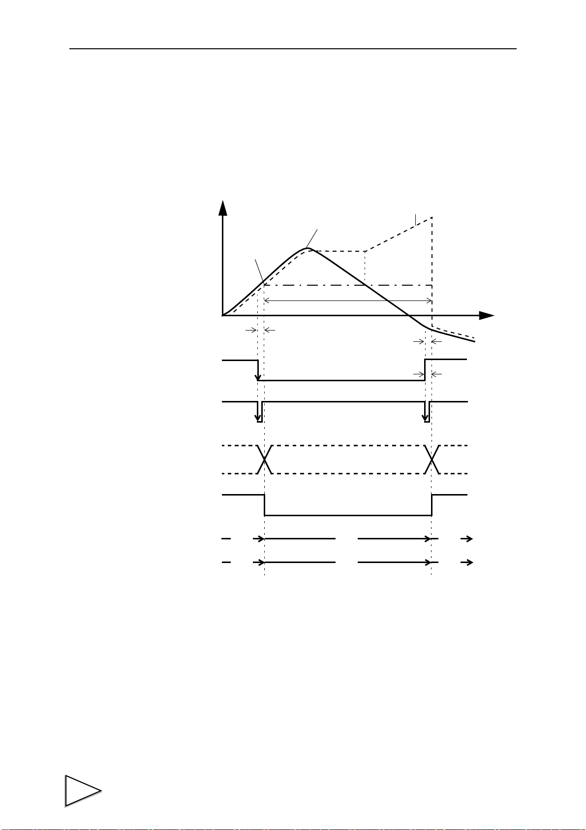
7-5-5. Relative Maximum and Relative Minimum Hold
Indicated Value
t3
Sensor Input Value
Detection
t
+
HI-LO Limit
Judging Output
Hold Period
Decide
H/M
t2
t1
Auto Start Level
T/H
H/E
OFF
ON
OFF
ON
OFF
ON
OFF
ON
HOLD
PEAK
ON
Blink ON
OFF
※ ON
OFF
OFF
OFF
HOLD
Buttun
OFF
ON
or
OFF
※ Comes on if a value is held with conditions met in the
detection period, and goes out if a value is not held.
Detection starts when the indicated value crosses the auto start level with the H/M signal
inputted. Detection is performed as long as the H/M signal is on.
The hold is released by turning on the T/H signal as a reset signal.
The H/E output signal is on between the instant when the hold starts and the instant when
the T/H signal is turned on.
If the auto start level is not needed as a starting condition of the detection period, set
99999.
(Example) Relative Maximum Hold
7.HOLD FUNCTIONS
t1: A delay time between the instant when the indicated value exceeds the auto start
level and the instant when the value to be held is detected
0.5ms (max.)
t2:A delay time between the instant when the H/M signal is inputted and the instant
when the value to be held is detected
1.0ms (max.)
t3:A minimum reset signal width required for releasing the hold
1.0ms (min.)
57
Page 69

7.HOLD FUNCTIONS
The Hold Function in General
● The delay times of the judging signal and the H/E signal do not include a
delay time of the analog circuit (low-pass filter). Also, the delay times are
calculated without the digital filter. Since the judging signal and the H/E
signal are generated for the value produced through the analog and digital
filters, transmission of the signals becomes slower and the delay of each
output signal increases with enhancement of the filters.
● If the H/M signal is continuously input, the previously held value is reset by
the on timing, and hold operation newly starts.
58
Page 70
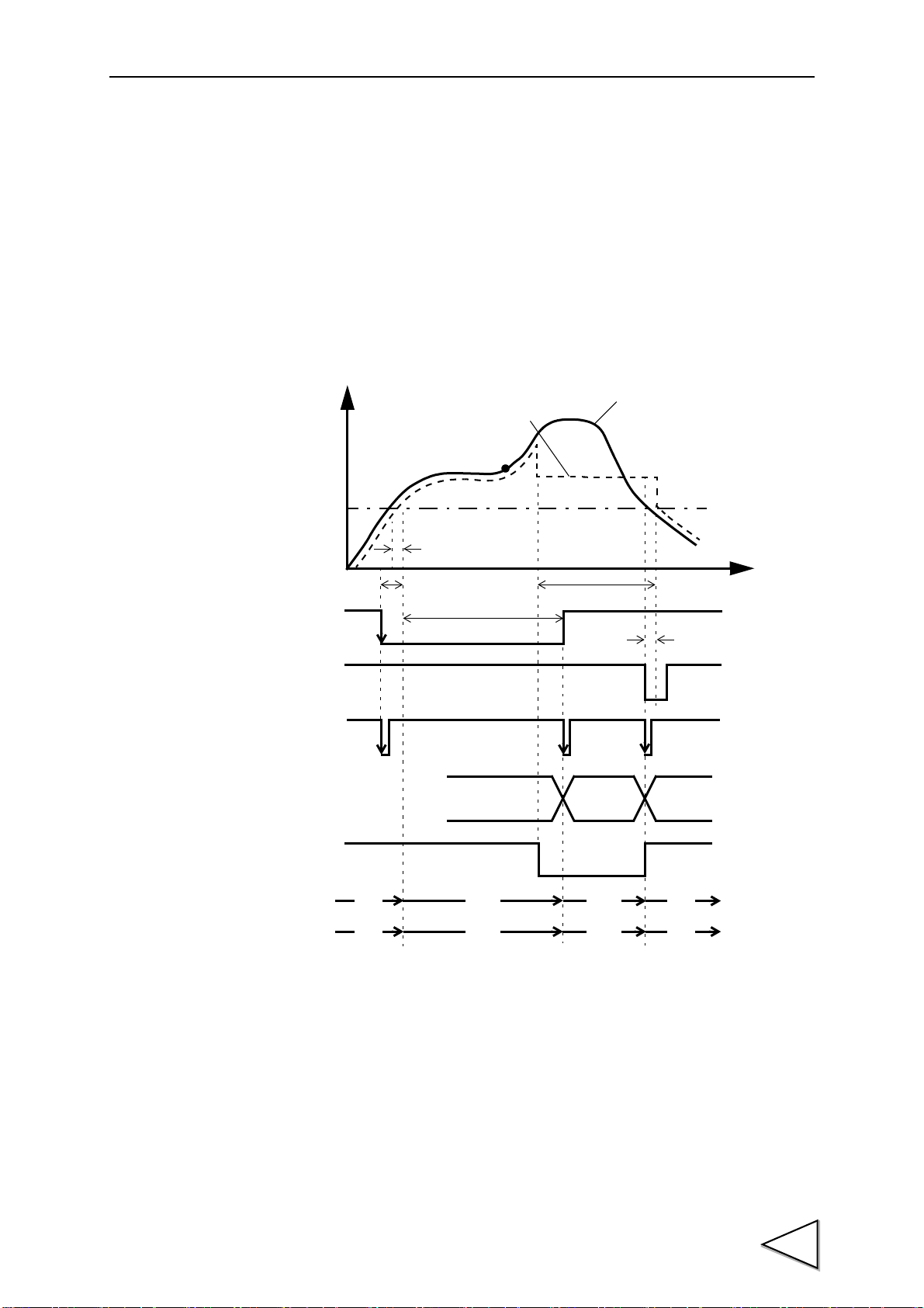
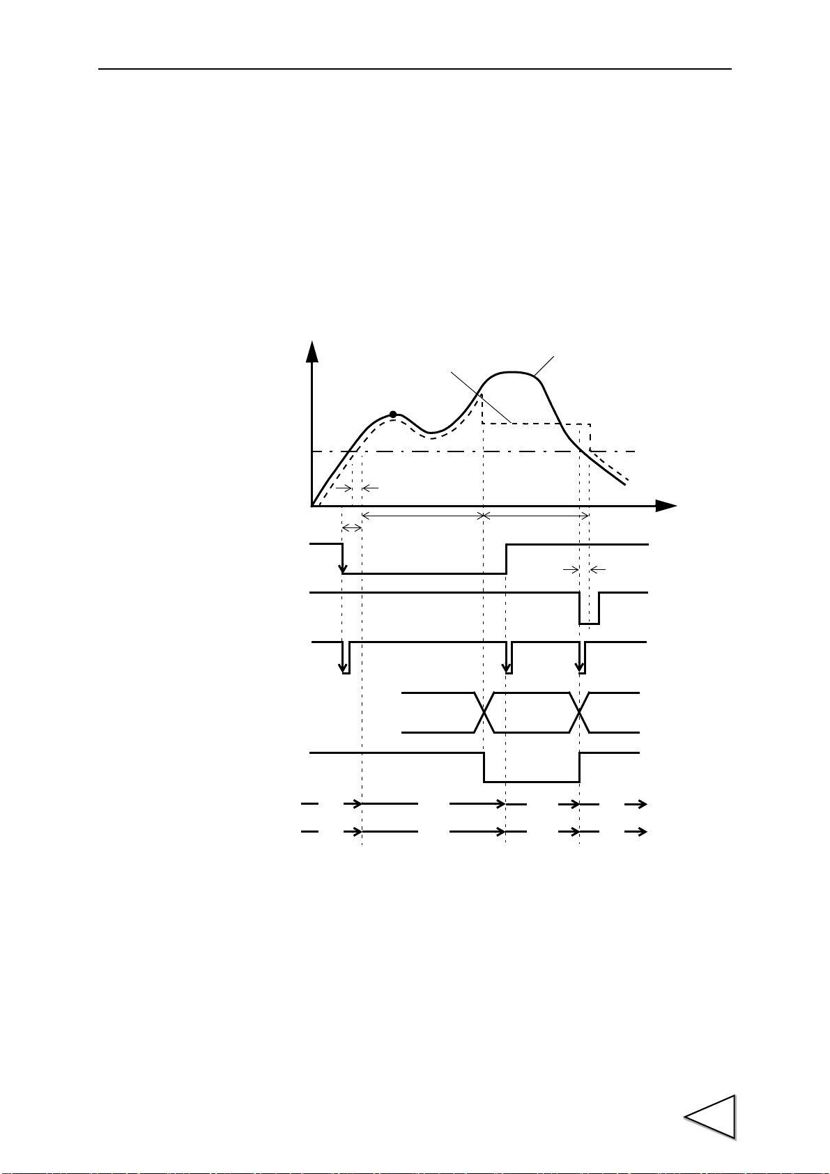
7-5-6. Inflection Point Hold
Indicated Value
t3
Sensor Input Value
Detection
t
+
HI-LO Limit
Judging Output
Hold Period
Decide
H/M
t2
t1
Auto Start Level
T/H
H/E
OFF
ON
OFF
ON
OFF
ON
OFF
ON
HOLD
PEAK
ON
Blink ON
OFF
※ ON
OFF
OFF
OFF
HOLD
Buttun
OFF
ON
or
OFF
※ Comes on if a value is held with conditions met in the
detection period, and goes out if a value is not held.
Detection starts when the indicated value crosses the auto start level with the H/M signal
inputted. Detection is performed as long as the H/M signal is on.
The hold is released by turning on the T/H signal as a reset signal.
The H/E output signal is on between the instant when the hold starts and the instant when
the T/H signal is turned on.
If the auto start level is not needed as a starting condition of the detection period, set
99999.
(Example) Inflection Point Hold
7.HOLD FUNCTIONS
t1: A delay time between the instant when the indicated value exceeds the auto start
level and the instant when the value to be held is detected
0.5ms (max.)
t2:A delay time between the instant when the H/M signal is inputted and the instant
when the value to be held is detected
1.0ms (max.)
t3:A minimum reset signal width required for releasing the hold
1.0ms (min.)
59
Page 71
7.HOLD FUNCTIONS
Real-time
Hold values
t
+
T/H
Judging Outpu
H/E
Decide
H/M
OFF
ON
OFF
ON
OFF
ON
OFF
ON
Indecided
t1 t1 t1
Detection
Hold Period
values
The detection period is limited by the maximum mean value detection
time set according to the “mean value sampling count”.
For details, see the section on Mean Value Sampling Count page 52.
7-5-7. Mean Value Hold
The mean value of the sampling values over the specified period is calculated and
updated to perform comparison operation.
The period is specified by the setting of “all period”, “external signal”, “time”, or “time
with trigger”.
(Example) Externally Specified Period Mean Value Hold
t1:A delay time between the instant when the T/H or H/M signal is inputted and the
instant when operation is performed.
1.0mS(MAX.)
60
Page 72
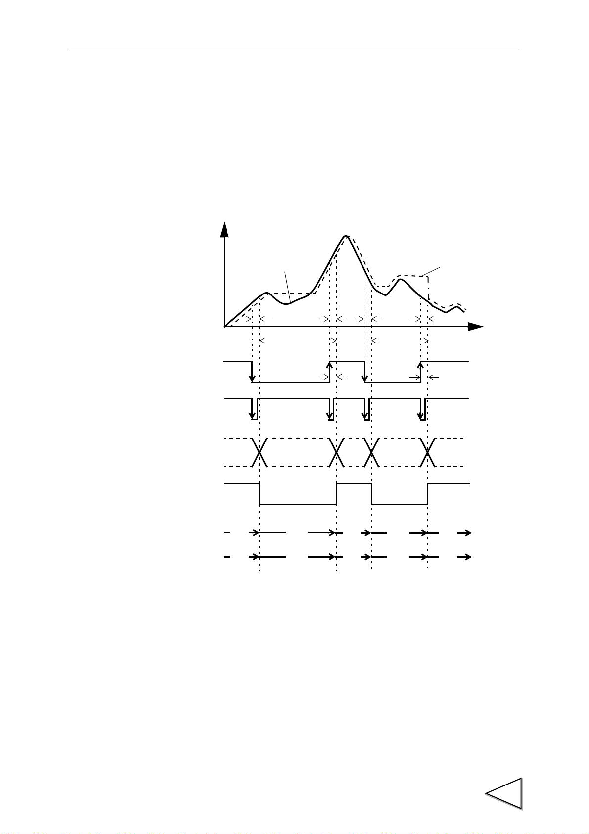
7-6. How to Specify the Hold Detection Period
Indicated Value
t2
t3
Sensor Input Value
Detection
t
+
T/H
HI-LO Limit
Judging Output
H/E
Detection
t1t2t1
t3
Note: During the undetermined period, the judging output varies with
fluctuations in the input waveform. However, the H/E output
remains on during the undetermined period. Read the judging
result when the indicated value becomes stable (immediately
before the T/H signal rises).
OFF
ON
OFF
ON
OFF
ON
OFF
ON
Status Display
PEAK
Status Display
ON
Blink Blink
OFF ON
OFF
OFF
OFF
OFF
OFF
HOLD
Button
Undetermind
Period(Note)
Undetermind
Period(Note)
Hold Period
Hold Period
HOLD
7-6-1. All Period
By this method, the hold detection period is externally specified by the T/H signal.
Detection starts with the T/H signal ON to perform each hold operation.
Detection ends with the T/H signal OFF to reset the hold.
(Example) All Period Peak Hold
7.HOLD FUNCTIONS
t1: A delay time between the instant when the T/H signal is inputted and the instant
when the indicated value is held
1.0ms (max.)
t2: A delay time between the instant when the T/H signal is released and the instant
when the indicated value returns to tracking
1.0ms (max.)
t3:A minimum reset signal width required for releasing the hold
1.0ms (min.)
61
Page 73
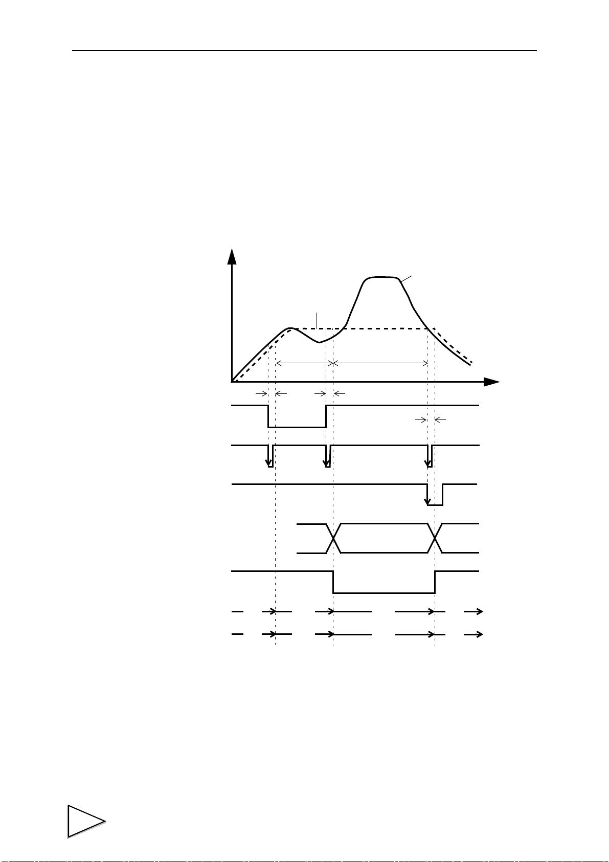
7.HOLD FUNCTIONS
Indicated Value
t3
Sensor Input Value
Detection
t
+
T/H
HI-LO Limit
Judging Output
H/E
Hold Period
t2t1
Decide
H/M
OFF
ON
OFF
ON
OFF
ON
OFF
ON
OFF
ON
HOLD
PEAK
ON
Blink ON
OFF ON
OFF
OFF
OFF
HOLD
Button
7-6-2. Externally Specified Period Hold
(Peak, Valley, Peak-to-Peak and Mean Value)
By this method, the hold detection period is externally specified by the H/M signal to
maintain the hold value until the reset signal is turned on.
The hold is released by turning on the T/H signal as a reset signal.
The H/E output signal is on between the instant when the H/M signal is turned off and
the instant when the T/H signal is turned on.
(Example) Period Specified Peak Hold
t1:A delay time between the instant when the H/M signal is inputted and the instant
when the value to be held is detected
1.0ms (max.)
t2:A delay time between the instant when the H/M signal is released and the instant
when the value to be held is determined
1.08ms (max.)
t3:A minimum reset signal width required for releasing the hold
1.0ms (min.)
62
Page 74

7-6-3. Time Specified Period Hold
Indicated Value
t3
Sensor Input Value
Detection
t
+
HOLD
HI-LO Limit
Judging Output
H/E
Hold Period
t2t1
Decide
H/M
T/H
Time
OFF
ON
OFF
ON
OFF
ON
OFF
ON
OFF
ON
OFF
ON
HOLD
PEAK
ON
Blink ON
OFF ON
OFF
OFF
OFF
HOLD
Button
(Peak, Valley, Peak-to-Peak and Mean Value)
Hold is detected during the predetermined time (hold detection time) from the point in
time when the H/M signal is turned on. The hold is released by turning on the T/H signal
as a reset signal.
The H/E output signal is on between the instant when the H/M signal is turned off and
the instant when the T/H signal is turned on.
(Example) Time Specified Period Peak Hold
7.HOLD FUNCTIONS
t1:A delay time between the instant when the H/M signal is inputted and the instant
when the value to be held is detected
1.0ms (max.)
t2:A delay time between the instant when the hold detection time is expired and the
instant when the value to be held is determined
1.0ms (max.)
t3:A minimum reset signal width required for releasing the hold
1.0ms (min.)
63
Page 75

7.HOLD FUNCTIONS
Indicated Value
t3
Sensor Input Value
Detection
t
+
HOLD
HI-LO Limit
Judging Output
H/E
Hold Period
t2t1
Decide
T/H
Time
Auto Start Level
OFF
ON
OFF
ON
OFF
ON
OFF
ON
OFF
ON
HOLD
PEAK
ON
Blink ON
OFF ON
OFF
OFF
OFF
HOLD
Button
7-6-4. Time Specified Period Hold with Trigger
(Peak, Valley, Peak-to-Peak and Mean Value)
Hold is detected during the predetermined time (hold detection time) from the point in
time when the indicated value crosses the auto start level. The hold is released by turning
on the T/H signal as a reset signal.
The H/E output signal is on between the instant when the hold detection time ends and
the instant when the T/H signal is turned on.
(Example) Time Specified Period Peak Hold with Trigger
t1: A delay time between the instant when the indicated value exceeds the auto start
t2: A delay time between the instant when the hold detection time is expired and the
64
t3:A minimum reset signal width required for releasing the hold
level and the instant when the value to be held is detected
0.5ms (max.)
instant when the value to be held is determined
1.0ms (max.)
1.0ms (min.)
Page 76

8. MULTI-HOLD FUNCTION
I/O terminal block
A6 COM2
A7 CODE0
B7 CODE1
A8 CODE2
B8 CODE3
Caution
It takes 15msec at the maximum for the
changed CH to become effective. During
this period, which CH is used for
comparison is undefined.
Also, when the CH is switched, the hold and
graph functions are reset to wait for starting
with the after-switching CH conditions
irrespective of the previous operation.
By this function, up to 16 types of hold and comparison set values can be stored and
selected with external switching signals of CODE0 - CODE3.
Normally, if there is no entry for CODE0 - CODE3, the set value of CH0 is selected, but
when CODE0 - CODE3 are in the following conditions, the set value of each setting CH
is selected.
CODE3 CODE2 CODE1 CODE0 SettingCH
0 0 0 0 SettingCH00
0 0 0 1 SettingCH01
0 0 1 0 SettingCH02
0 0 1 1 SettingCH03
0 1 0 0 SettingCH04
8.MULTI-HOLD FUNCTION
0 1 0 1 SettingCH05
0 1 1 0 SettingCH06
0 1 1 1 SettingCH07
1 0 0 0 SettingCH08
1 0 0 1 SettingCH09
1 0 1 0 SettingCH10
1 0 1 1 SettingCH11
1 1 0 0 SettingCH12
1 1 0 1 SettingCH13
1 1 1 0 SettingCH14
1 1 1 1 SettingCH15
(0: open, 1: short)
65
Page 77

8.MULTI-HOLD FUNCTION
How to set
8-1. About Changing of the Setting CH
When changing the hold or comparison set value of each CH, set the CH No. with the
CH change key on the mode selection screen, and change the set value.
1)Select the setting CH on the mode setting screen.
2)Then, enter each set value in a likewise manner.
66
Page 78

9. WAVEFORM DISPLAY
X-axis (time axis)
Graphic display START/STOP
Cursor move keys (The cursor moves on the X-axis.)
Cursor ON/OFF key
Y-axis (load axis)
Caution
When the cursor display is on and when the setting screen is open,
the graph is not upgraded.
Indicated value display(At cursor ON time, the cursor
point (green) value is displayed.)
9-1. Graphic Display Screen
Graph is updated while usually operating on the display screen (a comparison ,a hold
,graph ).
9.WAVEFORM DISPLAY
67
Page 79

9.WAVEFORM DISPLAY
Held
point
Example) Relative maximum hold
Plotting Range
D Z
100
Y
X
200
X End Point
Y End Point
Y Start Point
0
9-1-1. Hold Point Plotting
By using the hold function and the graph plotting function together, the held point (red)
can be plotted.
9-1-2. X-axis and Y-axis on the Graph Plotting Screen
X-axis
Y-axis
The X-axis is a time setting axis. One graph screen is plotted between the start signal
input point and the X start point.
There are 200 plotting points, and typical values for the predetermined time divided by
this number of plotting points are plotted.
The Y-axis is a load setting value. A graph is plotted between the Y start point and the Y
end point. (There are 100 plotting points.)
68
Page 80
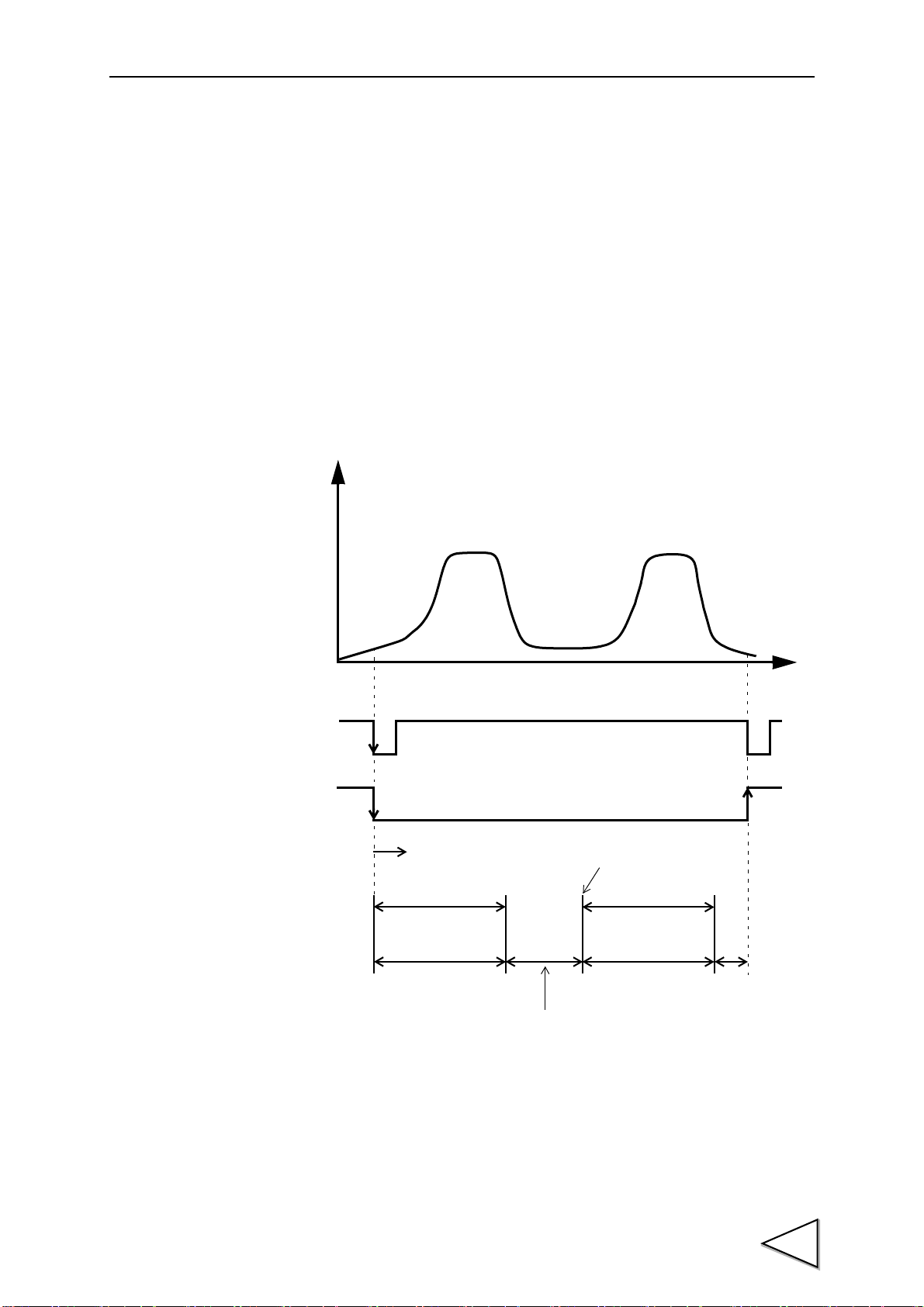
9-2. Graph Plotting
t
+
START/STOP
ST/SP
Star t
Plotting Period
(Screen Hold)
Plotting Period
X end point
X end point
Screen Clear
Interval Time
(Key)
(Outside Input)
time setteing
time setteing
9-2-1. Continuous
Graph plotting is started by turning on the START/STOP key or turning on the ST/SP
external input. When it ends on one screen, the screen is cleared after expiration of the
interval time and graph plotting restarts on the next screen. It is ended by turning off the
START/STOP key or turning off the ST/SP external input.
9.WAVEFORM DISPLAY
69
Page 81

9.WAVEFORM DISPLAY
t
+
START/STOP
ST/SP
(Key)
Plotting
X end point time setteing Screen Hold、
Period
Trigger wait
1.0msec more
9-2-2. External
Plotting is started by turning on the START/STOP key or turning on the ST/SP external
input.
Plotting ends on one screen at the predetermined time of the X end point.
70
Page 82
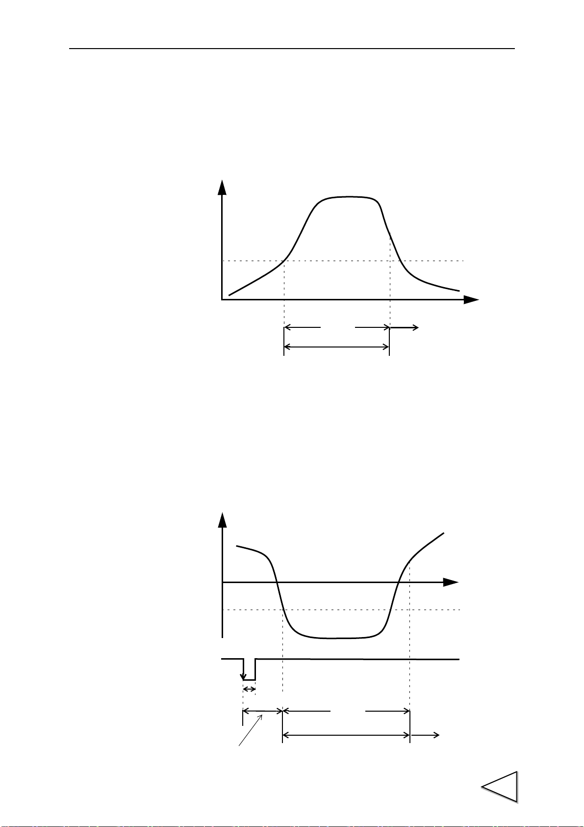
9-2-3. Level
t
+
X end point time setteing
Screen Hold、Trigger wait
Trigger Level
Plotting
Period
t
+
ST/SP
(Outside Input)
X end point time setteing
Trigger Level
Level Detection Period
Plotting
Period
Screen Hold、Trigger wait
1.0msec more
9.WAVEFORM DISPLAY
Plotting is started when the conditions of the detection mode are met in comparison of
the trigger level set value and indicated value.
Plotting ends on one screen at the predetermined time of the X end point.
9-2-4. External + Level
Plotting is started according to the conditions of the level detection mode in comparison
of the trigger level and indicated value after the ST/SP external input is turned on.
Plotting ends on one screen at the predetermined time of the X end point.
(Example) Level Detection Mode → Passing under.
71
Page 83

9.WAVEFORM DISPLAY
How to set
How to set
How to set
Setting call Page 1
→
→
Graph
Setting call Page 1
→
→
Graph
Setting call Page 1
→
→
Graph
9-3. Graph Function
Set the graph plotting mode.
Modes
9-4. Interval Time
Continuous, external, level, external + level
If you select "continuous" in the graph function setting, set the graph plotting operation
interrupting time from clearing the screen until moving to the next graph plotting
operation. During this time, the graph screen is held.
Setting range: 00.0 - 99.9 sec.
9-5. Graph Start Level
If you select [level] or [external + level] in the graph function setting, set the graph
plotting start level.
Setting range: -99999 - 99999
72
Page 84

9-6. Level Detection Mode
How to set
Setting call Page 1
→
→
Graph
- Passing
Graph plotting starts when the indicated value crosses the level
set value.
- Passing over
Graph plotting starts when the indicated value crosses the level
set value upward.
- Passing under
Graph plotting starts when the indicated value crosses the level
set value downward.
- Large
Graph plotting starts when the indicated value is larger than
the level set value.
- Small
Graph plotting starts when the indicated value is smaller than
the level set value.
If you select [level] or [external + level] in the graph function setting, set the graph
plotting start level comparison conditions.
Conditions: passing, passing over, passing under, large, small
9.WAVEFORM DISPLAY
73
Page 85
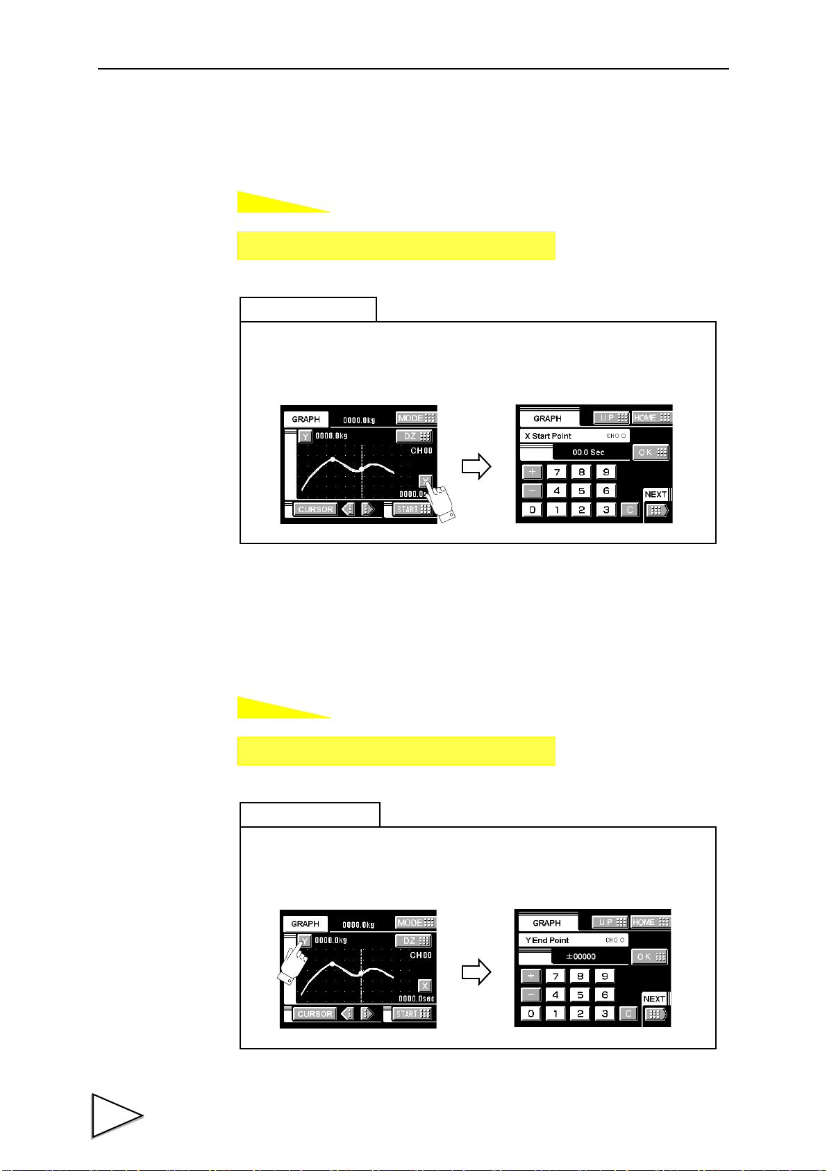
9.WAVEFORM DISPLAY
How to set
How to set
Setting call Page 1
→
→
Graph
Press the X button on the graph display to go direct to the X end point entry screen.
Simple setting call
Setting call Page 2
→
→
Graph
Press the Y button on the graph display to go direct to the Y end point entry screen.
Simple setting call
9-7. X Start Point
Set the time to display by one screen in the range between 0.1 sec. and 99.9 sec.
9-8. Y (Load) Start Point and Y (Load) End Point
Setting range: -99999 - 99999 (where Y start point < Y end point)
74
Page 86
10. BCD DATA OUTPUT(OPTION)
The BCD data output is an interface to extract the indicated value of the F370 as BCD
data. This interface is convenient to process controls, totals, records, etc., by connecting
the F370 to a computer, process controller, sequencer or the like.
The I/O and internal circuits are electrically insulated by photocoupler.
The data output rate can be selected from once/sec., 10 times/sec., 100 times/sec., and
1000 times/sec.
10-1. Connector Pin Assignment
Anphenol Connector(36-Pin)
10.BCD DATA OUTPUT(OPTION)
No. Signal No. Signal
1
*
2 Out 1 20 Out 20000
3 Out 2 21 Out 40000
4 Out 4 22 Out 80000
5 Out 8 23 Out Minus(Polarity)
6 Out 10 24 Out OVER
7 Out 20 25 Out
8 Out 40 26 Out STROBE
9 Out 80 27 In
10 Out 100 28 In Logic Switching
11 Out 200 29
12 Out 400 30
13 Out 800 31
14 Out 1000 32
COM 19
*
COM
P. C(Stable)
BCD Data Hold
15 Out 2000 33
16 Out 4000 34
17 Out 8000 35
18 Out 10000 36
Compatible connector is DDK57-30360 or equivalent.
75
Page 87
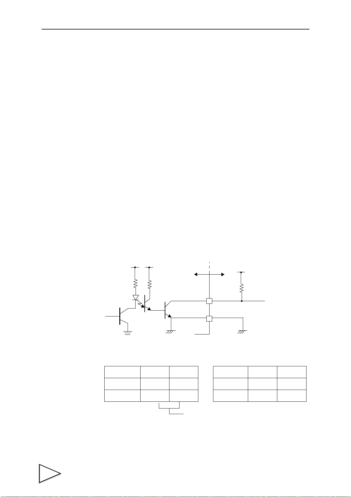
10.BCD DATA OUTPUT(OPTION)
F370
Inside
Vcc
+5V
COM
Ve xt
Vceo=30V(max)
Ic =30mA (max)
● Internal transistor status
Output data Negative Positive
0OFFON
1ONOFF
● Output pin level
Output data Negative Positive
0
HL
1
LH
Through logic switching(pin28)
Outside
10-2. Logic Change
Select the logic of output signals with pin No. 28.
When COM and pin No. 28 are open: negative logic
When they are short-circuited: positive logic
10-3. BCD Data Hold
The BCD data output signal is held. Switching is carried out by pin No. 27.
When COM and pin No. 27 are open: hold cancel
When they are short-circuited: hold on
10-4. Equivalent Circuit
・Output
The signal output circuit is operated through a TTL open collector.
76
Page 88
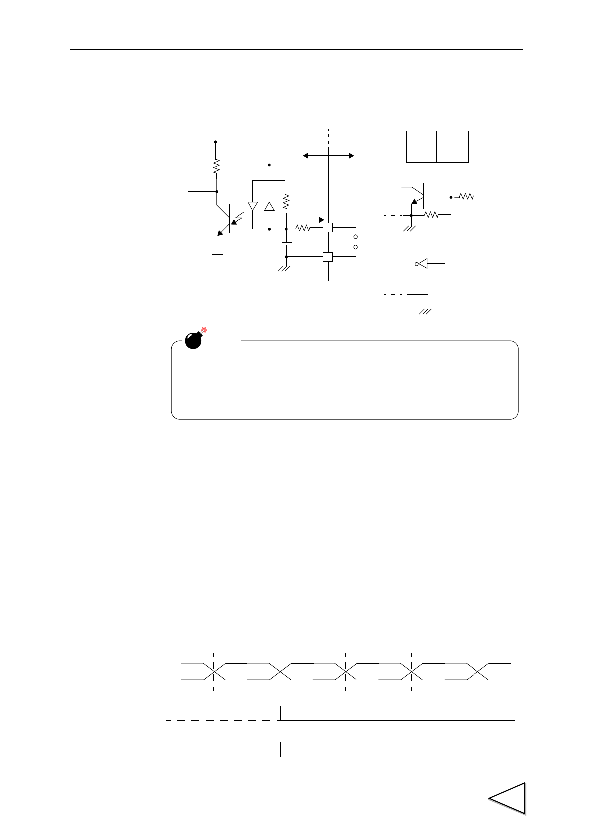
・Input
Vcc
F370
Inside
IC=Approx.6mA
COM
Switch
Transistor
+5V
TTL open collector output
Open OFF
Short ON
NOTE
- Do not apply external voltage to the signal input circuit.
- The external element is required to withstand Ic=10mA.
- Leakage from the external element is required to be 30μA or below.
Outside
(ON when IN is HI)
0
1
BCDdata
P. C
0
1
OVER
10.BCD DATA OUTPUT(OPTION)
10-5. Signal Timing
・PC
This signal turns on at the same time as BCD data when stable.
・OVER
This signal is outputted at the time of -ADC OVER, +ADC OVER, +overflow or -
overflow.
77
Page 89
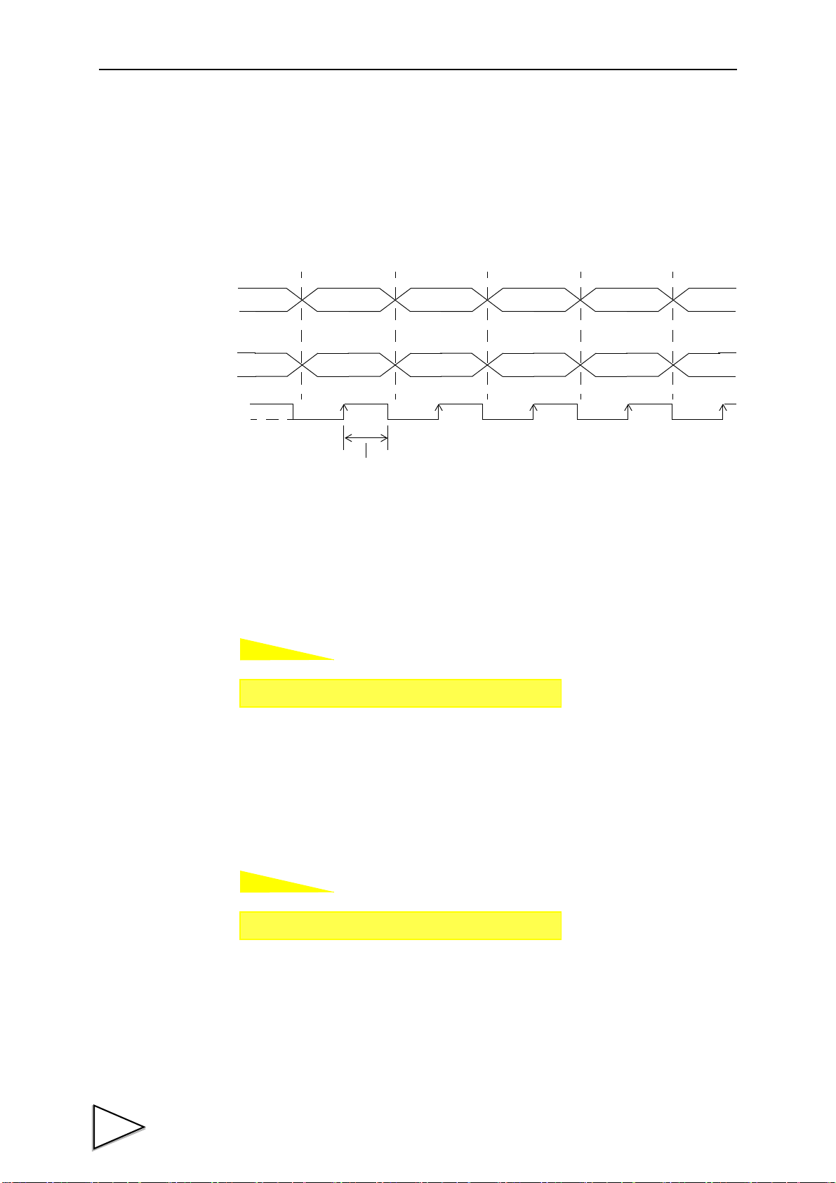
10.BCD DATA OUTPUT(OPTION)
How to set
How to set
BCDdata
OVER
Storobe range
STROBE
0
1
Setting call Page 1
→
→
Option
Setting call Page 1
→
→
Option
・STROBE
Strobe pulses are outputted in synchronization with BCD data. Read data using the rising
edges of the pulses. The BCD data update rate setting can be changed.
10-6. BCD Data Update Rate Selection
Output rate: 1, 10, 100, 1000 times
10-7. BCD Output Data Selection
Output data: Hold values, Real-time values
78
Page 90

11. RS-232C INTERFACE(OPTION)
RS232C
11.RS-232C INTERFACE(OPTION)
11-1. Communication Specifications
11-1-1. Specifications
Signal level: Based on RS-232C
Transmitting distance: Approx.15m
Transmitting method: Asynchronous,Full duplex
Transmitting speed: 1200,2400,4800,9600 or 19200bps Selectable
Bit configuration:
Start bit 1bit
Character length 7 or 8 bit Selectable
Stop bit 1 or 2 bit Selectable
Parity Parity none,odd or even Selectable
Terminator CR,CR+LF Selectable
Code: ASCII
79
Page 91

11.RS-232C INTERFACE(OPTION)
1
2
3
4
5
8
6
20
7
FG
TxD
RxD
RTS
CTS
(CD)
(DSR)
DTR
SG
1
2
3
4
5
8
6
20
7
FG
TxD
RxD
RTS
CTS
CD
DSR
DTR
SG
F370 PC etc・・・
Cross Cable
11-1-2. Connector Pin Assignment
Adaptable plug: 25-pin D-sub connector(JAE make DB-25P-N etc)
11-1-3. Cable
1
*
2 out TxD 15
3in RxD 16
4 out RTS 17
5in CTS 18
619
7
*
821
922
10 23
11 24
12 25
13
FG 14
SG 20 out DTR
* This connection diagram shows an example of connecting a DTE (data terminal
equipment) personal computer.
Use a straight cable for connecting a DCE (data circuit terminating equipment) such
as a modem.
80
* Before preparing a cable, check the connector shape and pin assignment of the
equipment to be connected again.
Page 92

11-2. RS-232C Interface Setting
How to set
How to set
How to set
How to set
Setting call Page 1
→
→
Option
Setting call Page 1
→
→
Option
Setting call Page 1
→
→
Option
Setting call Page 1
→
→
Option
Set the RS-232C communication conditions of the F370.
11-2-1. Communication Mode
Communication mode 0, communication mode 1, communication mode 2
11-2-2. Baud Rate
11.RS-232C INTERFACE(OPTION)
1200,2400,4800,9600,19200bps
11-2-3. Character Length
7bit,8bit
11-2-4. Parity Bit
None, odd, even
81
Page 93

11.RS-232C INTERFACE(OPTION)
How to set
How to set
Setting call Page 1
→
→
Option
Setting call Page 2
→
→
Option
11-2-5. Stop Bit
1 bit, 2 bit
11-2-6. Terminator
CR,CR + LF
11-3. Communication Modes
1.Communication Mode 0
Communications are carried out by commands from the host computer.
The indicated value, status and parameters can be read, and parameters can be written.
2. Communication Mode 1
The indicated value and status are continuously transmitted.
3. Communication Mode 2
The indicated value is transmitted upon printing.
82
Page 94

11-4. Communication Format
Host
F370
RA CR
RA
Ter mi nat or
+
1 0 0 0 0 .
Host
F370
RD CR
R D 0 0 0 0 0 0 0
1:ON
0:OFF
1:ON
0:OFF
Near Zero 1:ON
Output signal 0:OFF
HI 1:ON
Output signal 2:OFF
L O 1:ON
Output signal 0:OFF
OK 1:ON
Output signal 0:OFF
※ Undefined
Hold
Stable
Ter min at or
Host
F370
RC CR
R C 0 0 0 0 0 0 0
1:ON
0:OFF
1:ON
0:OFF
1:ON
0:OFF
1:ON
2:OFF
LL 1:ON
Output signal 0:OFF
HH 1:ON
Output signal 0:OFF
※ Undefined
+ LOAD
Ter min at or
- LOAD
+ OVER
- OVER
1. Communication Mode 0
- Reading the indicated value (sign, 5-digit indicated value, decimal point)
- Reading the status (7-digit)
11.RS-232C INTERFACE(OPTION)
※ The hold bit is operated at the same timing as the H/E signal.
83
Page 95

11.RS-232C INTERFACE(OPTION)
1
W
LF2
CR LF3 1
W
CR LF 41
W
CR
CR LF0 5 1
W
CR LF 8 4
W
CR LF 6 1
W
0
CR LF
①
1 2
W
0 0 0 0 0
CR LF 2 2
W
0 0
(Set Value
(Set Value
(Set Value
(Set Value
(Calibrationt Value
(Set Value
(Set Value
(Set Value
0
1
W
LF1CR
(Set Value
±
±
±
±
±
CR LF 32
W
±
CR LF 42
W
000
CR LF52
W
00 0 00
(Set Value
1 ~ 999
0 ~ 3
CR LF 62
W
0
CR LF 72
W
0
00
CR LF 82
W
0
010 ~ 120
010 ~ 120
00
Lock)
Lock)
Lock)
Lock)
Lock)
Lock)
Lock)
Lock)
Lock)
Lock)
CR LF ② 1 7
W
0 0 0 0 0
③
CR LF0 44
W
(Calibrationt Value
0
Lock)
000⑥
- Writing parameters
HI-HI Limit
HI limit
LO limit
LO-LO Limit
Hysteresis
Calibration Value
Selection
Digital
Offset Setting
Near Zero
Hold mode
Hold Section
Setup
Hold Detect Time
Auto Start Level
Minimum Count
valley Detect
Level
Minimum Slope
IntervalA
IntervalB
84
Page 96

Graph Function
CR LF 043
W
(Set Valu
0000
CR LF3 3
W
(Set Value
0
CR LF 0F1
W
000
Lock)
Lock)
⑤
3
W
LF1 CR
0 0000
3
W
LF2 CR
0 00
④
2
W
LF9 CR
0 00
Interval Time
Graph Start Level
Level Detect Mode
CH
Hold Point Shift
11.RS-232C INTERFACE(OPTION)
85
Page 97

11.RS-232C INTERFACE(OPTION)
① Hold mode
0: tracking 5: relative maximum
1: sample 6: relative minimum
2: peak 7: inflection point
3: valley 8: mean value
4: peak-to-peak
② Hold period setting
0: all period
1: external signal
2: time
3: time with trigger
③ Valley detection level
0: 1/4 times 4: 1.25 times
1: 1/2 times 5: 1.5 times
2: 3/4 times 6: 2 times
3: 1 time 7: 3 times
④ Graph mode
0: continuous
1: external
2: level
3: external + level
⑤ Level detection mode
0: passing
1: passing over
2: passing under
3: large
4: small
⑥ Calibration Value Selection
0: calibration value 0
1: calibration value 1
2
: calibration value 2
3: calibration value 3
Set value correspondence table
86
Page 98
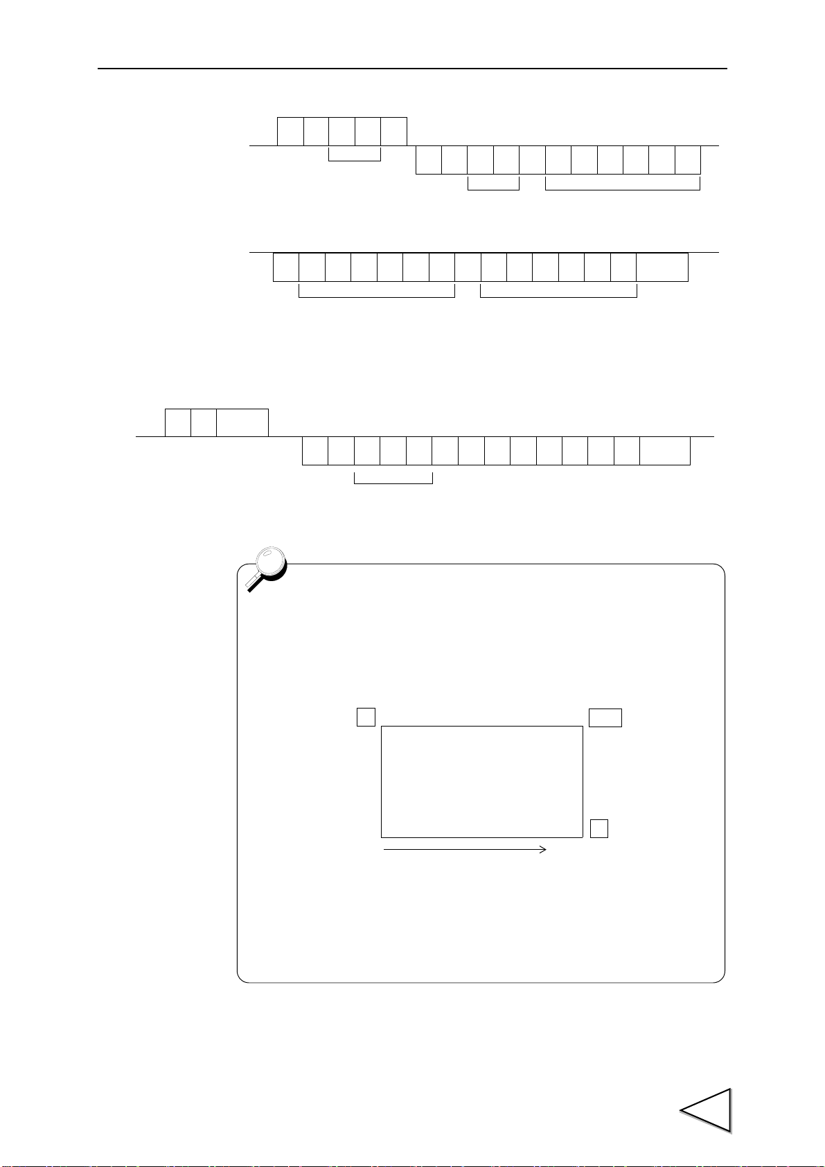
11.RS-232C INTERFACE(OPTION)
Host
F370
G
R
CR
Decimal Point and Five digits Data1
00 ~ 19
R
Data Section No.
G
±
00 ~ 19
Data Section No.
……
±±
……
Decimal Point and Five digits Data9 Decimal Point and Five digits Data10
Ter min at or
HOST
H
R
R
H
……
CR
+ 10 0 00.025 ,
DATA000 ~ 199
Ter min at or
One graph plotting screen includes 200 pieces of data. In reading
waveform data, data can be read by being divided into 20 sections
(by 10 pieces).
Data Section No.
Y
DZ
X
Plotting Range
Data 0
Data 199
Section 00 Data 0 ~ Data 9
Section 01 Data 10 ~ Data 19
Section 19 Data 190 ~ Data 199
~
- Reading waveform data
・Wave form hold point data read-out(data No, a mark, a decimal point,5 figures of
directions value)
87
Page 99
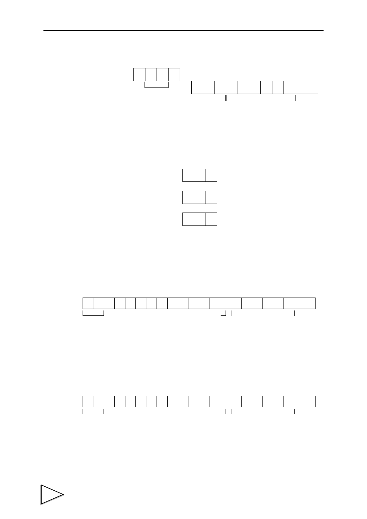
11.RS-232C INTERFACE(OPTION)
Host
F370
W
W
CR
Set Value No. The same format as write-in
of set values.
Set Value No.
Terminator
CR
CR
CR
C
C
C
G
F
I
(This is effctive only when the set value
(This is effctive only when the set value
(This will issue print a command onto SIF.)
LOCK is "1.")
LOCK is "1.")
0 1 2 3 4 5 6 7 8 9 10 11 12 13 14 15 16 17 18 19 20 21
G S , 1 , 2 , 3 , 4 , 5 , ±
****
HEADER
Five digits of the indicated
Sign
+ or -
*
Ter min at or
value and decimal point
0 1 2 3 4 5 6 7 8 9 10 11 12 13 14 15 16 17 18 19 20 21
G S , 1 , 2 , 3 , 4 , 5 , ±
****
HEADER
Five digits of the indicated
Sign
+ or -
*
Ter min at or
value and decimal point
- Reading parameters
- Commands (Host → F370)
Digital Zero
Digital Zero reset
Print instruction
2. Communication mode 1
The indicated value is continuously transmitted.
3. Communication mode 2
The indicated value is transmitted upon printing.
88
Page 100

* 1
O........ Over Load(LOAD,OFL)
S ........ Stable
M....... Not Stable
H........ Hold
* 1Priority H > O >(S or M)
* 2
A........Zero Tracking OFF
T ........Zero Tracking ON
11.RS-232C INTERFACE(OPTION)
* 3
H........High Limit ON
L ........Low Limit ON
G........High Limit and Low Limit OFF
N........High Limit and Low Limit ON
F ........Compare OFF
* 3Priority N >(H or L ) F > G
* 4
H........High High Limit ON
L ........Low Low Limit ON
G........High High Limit and Low Low Limit OFF
N........High High Limit and Low Low Limit ON
F ........Compare OFF
* Priority N >(H or L)F > G
* 5
N........Near Zero OFF
Z ........Near Zero ON
89
 Loading...