


F350
OPERATION MANUAL
01MAR2015REV.1.04

Introduction
Applications
Introduction
Introduction
Thank you very much for purchasing our Digital Indicator F350.
The F350 is an indicator for various strain gauge sensors that measure pressure, load, torque, etc. Equipped
with ultrahigh-speed peek hold and HI/LO limit comparison functions, the F350 is for general purpose use,
such as an automatic assembly machine and testing machine.
To take full advantage of high performance of F350, thoroughly read this operating manual first before use
and understand the explanations contained herein for correct operating procedures.Also, carefully store
this instruction manual so that it can be referred to at any time.
I
I

Safety Precautions
WARNING
CAUTION
This sign forewarns the presence of hazards
that could result in serious injury or fatality
when incorrectly handled.
Warning on design
Safety Precautions
Safety Precautions
BE SURE TO READ FOR SAFETY
Installation, maintenance and inspection of the F350 should be performed by personnel having technical
knowledge of electricity.
In order to have an F350 Weighing Controller used safely, notes I would like you to surely follow divide
into " " and " ", and are indicated by the following documents.
Notes indicated here are the serious contents related to safely.
Please use F350 after understanding the contents well.
This sign forewarns the presence of hazards that could result in serious injury
or fatality when incorrectly handled.
WARNING
CAUTION
This sign forewarns the presence of hazards that could result in personnel
injury or property damage when incorrectly handled.
WARNING
● For the entire system to function safely when the F350 becomes faulty or malfunctions,
provide a safety circuit outside the F350.
● Since the F350 has no power switch, install a breaker.
● Before using the F350 as described below, make sure to consult with our sales personnel.
- Use in environments not described in the operation manual.
- Use greatly impacting human lives and assets, such as medical devices, transport devices
entertainment devices, and safety devices.
II
II

WARNING
This sign forewarns the presence of hazards
that could result in serious injury or fatality
when incorrectly handled.
Warning on installation
Warning on wiring
Warning during startup and maintenance
● Do not disassemble, repair, or modify the F350. Doing so may cause a fire or an electric
● Do not install in the following environments.
● Do not connect a commercial power source directly to the signal input/output terminals.
● Be sure to ground the protective ground terminal.
● The attached AC cable is designed for domestic use in Japan, and its rating is 125V AC,
WARNING
WARNING
shock.
- Places containing corrosive gas or flammable gas.
- Where the product may be splashed with water, oil or chemicals.
10A. For use at voltages exceeding the rating and for overseas use, have a separate AC
cable prepared.
● Before performing the following, make sure that no power is applied.
- Removal and installation of optional connectors and so forth;
- Wiring and connection of cables to a power input terminal;
- Wiring and connection of cables to a signal I/O terminal;
- Connection to protective grounding terminals.
● For connection to the signal input/output terminals, check the signal names and pin
assignment numbers, and then carry out wiring properly.
● After wiring, be sure to mount the attached terminal block cover. Otherwise, it may cause an
electric shock.
● To take measures against lightning surge, install a lightning surge protector (optionally
available).
● Do not connect anything to unused terminal(s).
● Before applying power, carefully check the wiring, etc.
● Use a power supply voltage and load within the specified and rated ranges.
● Do not damage the power cord. Doing so may cause fire or electric shocks.
● Do not touch any signal input/output terminal while applying power. Doing so may cause
electric shocks or malfunctions.
● If the cover of the main body is opened, it may cause an electric shock internally. Even if the
power is off, the internal capacitor is charged. Contact us for internal inspection or repair.
● In the case of smoke, an abnormal smell or strange sound, immediately turn off the power,
and disconnect the power cable.
III
III

CAUTION
This sign forewarns the presence of hazards
that could result in personnel injury or property
damage when incorrectly handled.
Caution on installation
Caution on wiring
Caution during startup and maintenance
CAUTION
CAUTION
● Use the F350 as it is incorporated in a control panel, etc.
● Do not install in the following environments.
- Locations where temperature or humidity exceeds specifications;
- Locations subjected to drastic temperature fluctuations or icing and condensing;
- Outdoors or locations above 2,000m;
- Locations exposed to direct sunlight;
- Locations subject to dust accumulation;
- Locations with poor ventilation;
- Locations with a lot of salt and metal powder;
- Locations where the main unit is subject to direct vibration and shock.
● Take adequate shielding measures when using at the following locations.
- Near a power line.
- Where a strong electric field or magnetic field is formed.
- Where static electricity, relay noise or the like is generated.
● Install the F350 as far away from devices generating high frequency, high voltage, large
current, surge, etc., as possible. Also, carry out wiring separately from their power lines. Do
not carry out parallel wiring and common wiring.
● Do not use it, broken down.
● Tighten the screws for the power input terminal at the specified torque.
If they are loose, shorts, fire or malfunctions may occur.
Tightening torque: 0.5N •m
● For sensors, external inputs/outputs and options, use shielded cables.
● The temporary overvoltage applied to the power should not exceed 1500V.
● For turning on/off the power, be sure to keep intervals of 5 seconds or more.
● After power-on, make sure to warm up the F350 for at least 30 minutes or more before use.
● If the F350 is not used by the specified method, its protective performance may be impaired.
● Maintenance
- When performing maintenance, disconnect the power.
- Do not wipe with a wet rag, or with benzine, thinner, alcohol, etc. Doing so may cause
discoloration or deformation of the F350. In the case of heavy contamination, wipe off
the contamination with a cloth after dipping it into a diluted neutral detergent and wringing
it well, and then wipe with a soft, dry cloth.
IV
IV

CAUTION
This sign forewarns the presence of hazards
that could result in personnel injury or property
damage when incorrectly handled.
Caution during transportation
Caution during disposal
This sign forewarns the presence of hazards
that could result in serious injury or fatality
when incorrectly handled.
CAUTION
CAUTION
● When the F350 is shipped, spacers made of corrugated cardboard are used as cushioning
materials.
Though it is factory-designed so that shocks can sufficiently be absorbed, breakage may
result if shocks are applied when the spacers are reused for transportation. If you send the
F350 to us for repair, etc., take adequate measures against shocks by using polyurethane
materials, etc., separately.
● If you dispose of the product, handle it as industrial waste.
About the Built-in Lithium Battery
WARNING
● Never disassemble, deform under pressure or throw the battery
into fire.The battery may explode, catch fire or leak.
V
V

Statement of Conformation to EC Directives
)
Overvoltage category II
Pollution degree 2
The combination of the main unit of the F350 and a lightning surge protector
conforms to EN61000-4-5 (lightning surge immunity) in the EMC Directives.
Refer to " Connection of a Lightning Surge Protector (Power Cable)" on page VII
for information regarding lightning surge protector connection.
Point
Statement of Conformation to EC Directives
Statement of Conformation to EC Directives
* The F350 is a CE-compliant product. For use, observe the following.
The F350 Digital Indicator is a CE-marked EC-Directive-conforming product
(by the Council of the European Union).
- Low Voltage Directive EN61010-1:2010
EN62311:2008 (test distance: 0cm)
- EMC Directive EN61326-1:2006
EN55011:2009, A1:2010 Group1, ClassA
EN61000-3-2:2006, A1:2009, A2:2009
EN61000-3-3:2008
EN61000-4-2:2009
EN61000-4-3:2006, A1:2008, A2:2010
EN61000-4-4:2004, A1:2010
EN61000-4-5:2006
EN61000-4-6:2009
EN61000-4-8:2010
EN61000-4-11:2004
When installing, attention should be given to the following.
1. Since the F350 is defined as open type (built-in equipment), be sure to use it as installed
and fixed to a panel, etc.
2. The power cable attached to this product as standard can be used with 100V AC power in
Japan.(Nominal rated voltage: 125V AC)
For using this product in a country outside Japan, use a power cable certified in that
country.
3. For cables other than the power cable (sensor, external input/output, option), use shielded
cables.
Also, mount the attached ferrite core to the strain gauge sensor cable.
VI
VI

Connection of a Lightning Surge Protector (Power Cable)
F350
Lightning surge protector
* MAINTRAB MNT-1D is a registered trademark of
PHOENIX CONTACT.
An EU-outlet-shape AC power cable is required.
CA325AC3P-CEE7/7-B2: CEE7/7 plug cable (2m)
Connection of a Lightning Surge Protector (Power Cable)
Connection of a Lightning Surge Protector
(Power Cable)
Connect a lightning surge protector against lightning surge.
EMC Directive EN61000-4-5 (Lightning Surge Immunity) is met by the F350 body in combination with a
lightning surge protector.
●Lightning surge protector [MAINTRAB MNT-1D]
The lightning surge protector [MAINTRAB MNT-1D] is not included as standard.
In addition, as optional parts, we sell EU-outlet-shape 250V AC withstanding cables (following illustration:
European standard) and lightning surge protectors in pairs (TSU02). For details, contact our sales
department.
RoHS-Compliant Product
The parts and attachments (including the instruction manual, packaging box, etc.) used for this unit are
compliant with the RoHS Directive restricting the use of hazardous substances with regard to adverse
effects on the environment and human body.
What is RoHS?
It is an abbreviation for Restriction on Hazardous Substances, which is implemented by the European
Union (EU). The Directive restricts the use of six specific substances in electric and electronic equipment
handled within EU borders. The six substances are lead, mercury, cadmium, hexavalent chromium, PBB
(polybrominated biphenyls), and PBDE (polybrominated diphenyl ethers).
VII
VII

CONTENTS
CONTENTS
CONTENTS
1 OUTLINE . . . . . . . . . . . . . . . . . . . . . . . . . . . . . . . . . . . . . . . . . . . . . . . . . . . . 1
1-1. Main features of the F350. . . . . . . . . . . . . . . . . . . . . . . . . . . . . . . . . . . . . . . . . . . . . . . 1
1-2. Contents of the package. . . . . . . . . . . . . . . . . . . . . . . . . . . . . . . . . . . . . . . . . . . . . . . . 2
1-3. About connectable devices. . . . . . . . . . . . . . . . . . . . . . . . . . . . . . . . . . . . . . . . . . . . . . 3
1-4. Appearance description . . . . . . . . . . . . . . . . . . . . . . . . . . . . . . . . . . . . . . . . . . . . . . . . 3
2 INSTALLATION & CONNECTION. . . . . . . . . . . . . . . . . . . . . . . . . . . . . . . . . 7
■ Front panel . . . . . . . . . . . . . . . . . . . . . . . . . . . . . . . . . . . . . . . . . . . . . . . . . . . . . 3
■ Rear panel. . . . . . . . . . . . . . . . . . . . . . . . . . . . . . . . . . . . . . . . . . . . . . . . . . . . . . 6
2-1. Installation . . . . . . . . . . . . . . . . . . . . . . . . . . . . . . . . . . . . . . . . . . . . . . . . . . . . . . . . . . 8
2-2. Connection . . . . . . . . . . . . . . . . . . . . . . . . . . . . . . . . . . . . . . . . . . . . . . . . . . . . . . . . . .9
■ Power input terminal connection . . . . . . . . . . . . . . . . . . . . . . . . . . . . . . . . . . . . . 9
■ Analog input/output connector connection . . . . . . . . . . . . . . . . . . . . . . . . . . . . 10
■ How to remove the terminal block . . . . . . . . . . . . . . . . . . . . . . . . . . . . . . . . . . . 10
■ How to connect and install the terminal block . . . . . . . . . . . . . . . . . . . . . . . . . . 11
■ Attachment of a ferrite core . . . . . . . . . . . . . . . . . . . . . . . . . . . . . . . . . . . . . . . . 11
■ Strain gauge sensor connection . . . . . . . . . . . . . . . . . . . . . . . . . . . . . . . . . . . . 12
■ Strain gauge sensor cable coloration . . . . . . . . . . . . . . . . . . . . . . . . . . . . . . . . 13
■ Voltage output connection. . . . . . . . . . . . . . . . . . . . . . . . . . . . . . . . . . . . . . . . . 13
■ External I/O connection . . . . . . . . . . . . . . . . . . . . . . . . . . . . . . . . . . . . . . . . . . . 14
■ How to assemble the connector . . . . . . . . . . . . . . . . . . . . . . . . . . . . . . . . . . . . 15
■ SI/F interface connection. . . . . . . . . . . . . . . . . . . . . . . . . . . . . . . . . . . . . . . . . . 15
3 SETTING MODE CONFIGURATION. . . . . . . . . . . . . . . . . . . . . . . . . . . . . . 16
3-1. Setting mode composition . . . . . . . . . . . . . . . . . . . . . . . . . . . . . . . . . . . . . . . . . . . . . 16
3-2. Key operation . . . . . . . . . . . . . . . . . . . . . . . . . . . . . . . . . . . . . . . . . . . . . . . . . . . . . . . 18
3-3. Calling a setting mode . . . . . . . . . . . . . . . . . . . . . . . . . . . . . . . . . . . . . . . . . . . . . . . . 22
VIII
4 CALIBRATION PROCEDURE . . . . . . . . . . . . . . . . . . . . . . . . . . . . . . . . . . . 23
4-1. How to calibration . . . . . . . . . . . . . . . . . . . . . . . . . . . . . . . . . . . . . . . . . . . . . . . . . . . . 23
■ Equivalent input calibration . . . . . . . . . . . . . . . . . . . . . . . . . . . . . . . . . . . . . . . . 23
■ Actual load calibration . . . . . . . . . . . . . . . . . . . . . . . . . . . . . . . . . . . . . . . . . . . . 23
4-2. Procedure of equivalent input calibration and calibration protect. . . . . . . . . . . . . . . . 24
VIII

CONTENTS
CONTENTS
5 EXPLANATION OF INDICATED-VALUE-RELATED FUNCTIONS . . . . . . . 35
5-1. A/D conversion speed select . . . . . . . . . . . . . . . . . . . . . . . . . . . . . . . . . . . . . . . . . . . 35
■ A/D conversion speed select setting method . . . . . . . . . . . . . . . . . . . . . . . . . . 35
5-2. Analog filter . . . . . . . . . . . . . . . . . . . . . . . . . . . . . . . . . . . . . . . . . . . . . . . . . . . . . . . .36
■ Analog filter setting method. . . . . . . . . . . . . . . . . . . . . . . . . . . . . . . . . . . . . . . . 36
5-3. Digital filter . . . . . . . . . . . . . . . . . . . . . . . . . . . . . . . . . . . . . . . . . . . . . . . . . . . . . . . . . 37
■ Digital filter setting method . . . . . . . . . . . . . . . . . . . . . . . . . . . . . . . . . . . . . . . . 37
5-4. Digital Zero . . . . . . . . . . . . . . . . . . . . . . . . . . . . . . . . . . . . . . . . . . . . . . . . . . . . . . . . .38
■ Digital Zero / Digital Zero reset by means of keys . . . . . . . . . . . . . . . . . . . . . . 38
■ Digital Zero by means of the external signal "D/Z input". . . . . . . . . . . . . . . . . . 39
5-5. D/Z synchronous mode . . . . . . . . . . . . . . . . . . . . . . . . . . . . . . . . . . . . . . . . . . . . . . . 39
■ D/Z synchronous mode setting method . . . . . . . . . . . . . . . . . . . . . . . . . . . . . . 39
5-6. Zero Tracking . . . . . . . . . . . . . . . . . . . . . . . . . . . . . . . . . . . . . . . . . . . . . . . . . . . . . . . 40
■ Zero Tracking setting method . . . . . . . . . . . . . . . . . . . . . . . . . . . . . . . . . . . . . . 40
5-7. Motion Detect . . . . . . . . . . . . . . . . . . . . . . . . . . . . . . . . . . . . . . . . . . . . . . . . . . . . . . . 41
■ Motion Detect setting method . . . . . . . . . . . . . . . . . . . . . . . . . . . . . . . . . . . . . . 42
5-8. Display frequency . . . . . . . . . . . . . . . . . . . . . . . . . . . . . . . . . . . . . . . . . . . . . . . . . . . . 43
■ Display frequency setting method . . . . . . . . . . . . . . . . . . . . . . . . . . . . . . . . . . . 43
6 EXPLANATION OF COMPARISON FUNCTIONS . . . . . . . . . . . . . . . . . . . . 44
6-1. Calculation mode . . . . . . . . . . . . . . . . . . . . . . . . . . . . . . . . . . . . . . . . . . . . . . . . . . . . 44
■ Calculation mode setting method . . . . . . . . . . . . . . . . . . . . . . . . . . . . . . . . . . . 44
6-2. HI/LO limit comparison of calculated value / ch1 value / ch2 value . . . . . . . . . . . . . . 45
■ HI/LO limit setting method . . . . . . . . . . . . . . . . . . . . . . . . . . . . . . . . . . . . . . . . . 45
6-3. Hysteresis. . . . . . . . . . . . . . . . . . . . . . . . . . . . . . . . . . . . . . . . . . . . . . . . . . . . . . . . . .45
■ Hysteresis setting method . . . . . . . . . . . . . . . . . . . . . . . . . . . . . . . . . . . . . . . . . 46
6-4. Near Zero . . . . . . . . . . . . . . . . . . . . . . . . . . . . . . . . . . . . . . . . . . . . . . . . . . . . . . . . . .47
■ Near Zero setting method . . . . . . . . . . . . . . . . . . . . . . . . . . . . . . . . . . . . . . . . . 47
6-5. Calculation comparison timing . . . . . . . . . . . . . . . . . . . . . . . . . . . . . . . . . . . . . . . . . . 48
■ Calculation comparison timing setting method . . . . . . . . . . . . . . . . . . . . . . . . . 48
IX
6-6. Comparison OK output conditions . . . . . . . . . . . . . . . . . . . . . . . . . . . . . . . . . . . . . . . 49
■ Comparison OK output conditions setting method . . . . . . . . . . . . . . . . . . . . . . 49
7 EXPLANATION OF HOLD FUNCTIONS . . . . . . . . . . . . . . . . . . . . . . . . . . . 50
7-1. Hold functions of calculated values . . . . . . . . . . . . . . . . . . . . . . . . . . . . . . . . . . . . . . 50
IX

CONTENTS
CONTENTS
■ Flow of hold measurement . . . . . . . . . . . . . . . . . . . . . . . . . . . . . . . . . . . . . . . . 50
7-2. Setting of hold mode. . . . . . . . . . . . . . . . . . . . . . . . . . . . . . . . . . . . . . . . . . . . . . . . . . 51
■ Hold mode setting method . . . . . . . . . . . . . . . . . . . . . . . . . . . . . . . . . . . . . . . . 51
■ Sample hold . . . . . . . . . . . . . . . . . . . . . . . . . . . . . . . . . . . . . . . . . . . . . . . . . . . 51
■ Peak hold . . . . . . . . . . . . . . . . . . . . . . . . . . . . . . . . . . . . . . . . . . . . . . . . . . . . . 52
■ Bottom hold . . . . . . . . . . . . . . . . . . . . . . . . . . . . . . . . . . . . . . . . . . . . . . . . . . . . 52
■ Average hold . . . . . . . . . . . . . . . . . . . . . . . . . . . . . . . . . . . . . . . . . . . . . . . . . . . 53
■ Average sample number . . . . . . . . . . . . . . . . . . . . . . . . . . . . . . . . . . . . . . . . . . 53
7-3. Setting of hold section . . . . . . . . . . . . . . . . . . . . . . . . . . . . . . . . . . . . . . . . . . . . . . . . 54
■ Hold section setting method . . . . . . . . . . . . . . . . . . . . . . . . . . . . . . . . . . . . . . . 54
■ All section . . . . . . . . . . . . . . . . . . . . . . . . . . . . . . . . . . . . . . . . . . . . . . . . . . . . . 55
■ External signal. . . . . . . . . . . . . . . . . . . . . . . . . . . . . . . . . . . . . . . . . . . . . . . . . . 56
■ External signal + time . . . . . . . . . . . . . . . . . . . . . . . . . . . . . . . . . . . . . . . . . . . . 57
7-4. Auto reset function . . . . . . . . . . . . . . . . . . . . . . . . . . . . . . . . . . . . . . . . . . . . . . . . . . . 58
■ Auto reset setting method . . . . . . . . . . . . . . . . . . . . . . . . . . . . . . . . . . . . . . . . . 59
8 STANDARD INTERFACE . . . . . . . . . . . . . . . . . . . . . . . . . . . . . . . . . . . . . . 60
8-1. External I/O. . . . . . . . . . . . . . . . . . . . . . . . . . . . . . . . . . . . . . . . . . . . . . . . . . . . . . . . .60
■ Connector pin assignment. . . . . . . . . . . . . . . . . . . . . . . . . . . . . . . . . . . . . . . . . 60
■ About outputs . . . . . . . . . . . . . . . . . . . . . . . . . . . . . . . . . . . . . . . . . . . . . . . . . . 60
■ About inputs . . . . . . . . . . . . . . . . . . . . . . . . . . . . . . . . . . . . . . . . . . . . . . . . . . . 61
■ About the RUN signal . . . . . . . . . . . . . . . . . . . . . . . . . . . . . . . . . . . . . . . . . . . . 61
8-2. SI/F(Serial interface) . . . . . . . . . . . . . . . . . . . . . . . . . . . . . . . . . . . . . . . . . . . . . . . . 62
■ SI/F Indicated value format . . . . . . . . . . . . . . . . . . . . . . . . . . . . . . . . . . . . . . . . 62
■ SI/F print . . . . . . . . . . . . . . . . . . . . . . . . . . . . . . . . . . . . . . . . . . . . . . . . . . . . . . 62
9 OPTION INTERFACE . . . . . . . . . . . . . . . . . . . . . . . . . . . . . . . . . . . . . . . . . 64
9-1. BCD interface . . . . . . . . . . . . . . . . . . . . . . . . . . . . . . . . . . . . . . . . . . . . . . . . . . . . . . . 64
■ Connection . . . . . . . . . . . . . . . . . . . . . . . . . . . . . . . . . . . . . . . . . . . . . . . . . . . . 64
■ Connector pin assignment. . . . . . . . . . . . . . . . . . . . . . . . . . . . . . . . . . . . . . . . . 65
■ Output data select . . . . . . . . . . . . . . . . . . . . . . . . . . . . . . . . . . . . . . . . . . . . . . . 66
■ Signal timing . . . . . . . . . . . . . . . . . . . . . . . . . . . . . . . . . . . . . . . . . . . . . . . . . . . 66
■ Logic switching . . . . . . . . . . . . . . . . . . . . . . . . . . . . . . . . . . . . . . . . . . . . . . . . . 67
■ BCD data hold . . . . . . . . . . . . . . . . . . . . . . . . . . . . . . . . . . . . . . . . . . . . . . . . . . 67
■ Output rate . . . . . . . . . . . . . . . . . . . . . . . . . . . . . . . . . . . . . . . . . . . . . . . . . . . . 68
■ BCD/binary select . . . . . . . . . . . . . . . . . . . . . . . . . . . . . . . . . . . . . . . . . . . . . . . 68
■ Pin assignment at binary . . . . . . . . . . . . . . . . . . . . . . . . . . . . . . . . . . . . . . . . . . 69
9-2. RS-232C interface . . . . . . . . . . . . . . . . . . . . . . . . . . . . . . . . . . . . . . . . . . . . . . . . . . . 70
■ Communication specifications. . . . . . . . . . . . . . . . . . . . . . . . . . . . . . . . . . . . . . 70
■ Connector pin assignment. . . . . . . . . . . . . . . . . . . . . . . . . . . . . . . . . . . . . . . . . 70
■ Connection . . . . . . . . . . . . . . . . . . . . . . . . . . . . . . . . . . . . . . . . . . . . . . . . . . . . 71
■ Communication mode . . . . . . . . . . . . . . . . . . . . . . . . . . . . . . . . . . . . . . . . . . . . 71
■ Communication conditions . . . . . . . . . . . . . . . . . . . . . . . . . . . . . . . . . . . . . . . . 72
■ Delimiter . . . . . . . . . . . . . . . . . . . . . . . . . . . . . . . . . . . . . . . . . . . . . . . . . . . . . . 72
■ Communication format . . . . . . . . . . . . . . . . . . . . . . . . . . . . . . . . . . . . . . . . . . . 73
X
X

CONTENTS
CONTENTS
■ Continuousness / print send mode . . . . . . . . . . . . . . . . . . . . . . . . . . . . . . . . . . 77
9-3. D/A converter output . . . . . . . . . . . . . . . . . . . . . . . . . . . . . . . . . . . . . . . . . . . . . . . . . 78
■ Connection . . . . . . . . . . . . . . . . . . . . . . . . . . . . . . . . . . . . . . . . . . . . . . . . . . . . 78
■ Output data select . . . . . . . . . . . . . . . . . . . . . . . . . . . . . . . . . . . . . . . . . . . . . . . 79
■ Zero/Full scale setting . . . . . . . . . . . . . . . . . . . . . . . . . . . . . . . . . . . . . . . . . . . . 80
■ Adjustment by fixed output . . . . . . . . . . . . . . . . . . . . . . . . . . . . . . . . . . . . . . . . 81
10 SPECIFICATIONS . . . . . . . . . . . . . . . . . . . . . . . . . . . . . . . . . . . . . . . . . . . . 82
10-1. Specifications . . . . . . . . . . . . . . . . . . . . . . . . . . . . . . . . . . . . . . . . . . . . . . . . . . . . . .82
■ Analog section. . . . . . . . . . . . . . . . . . . . . . . . . . . . . . . . . . . . . . . . . . . . . . . . . . 82
■ Display section . . . . . . . . . . . . . . . . . . . . . . . . . . . . . . . . . . . . . . . . . . . . . . . . . 82
■ Setting section. . . . . . . . . . . . . . . . . . . . . . . . . . . . . . . . . . . . . . . . . . . . . . . . . . 82
■ External input/output section. . . . . . . . . . . . . . . . . . . . . . . . . . . . . . . . . . . . . . . 83
■ Interface . . . . . . . . . . . . . . . . . . . . . . . . . . . . . . . . . . . . . . . . . . . . . . . . . . . . . . 83
■ Options . . . . . . . . . . . . . . . . . . . . . . . . . . . . . . . . . . . . . . . . . . . . . . . . . . . . . . . 83
■ General performance . . . . . . . . . . . . . . . . . . . . . . . . . . . . . . . . . . . . . . . . . . . . 84
■ Attachment . . . . . . . . . . . . . . . . . . . . . . . . . . . . . . . . . . . . . . . . . . . . . . . . . . . . 84
10-2.Dimensions. . . . . . . . . . . . . . . . . . . . . . . . . . . . . . . . . . . . . . . . . . . . . . . . . . . . . . . . .85
■ Standard equipment . . . . . . . . . . . . . . . . . . . . . . . . . . . . . . . . . . . . . . . . . . . . . 85
■ Equipped with BCD parallel data output interface option . . . . . . . . . . . . . . . . . 85
■ Equipped with RS-232C interface option . . . . . . . . . . . . . . . . . . . . . . . . . . . . . 86
■ Equipped with D/A converter option . . . . . . . . . . . . . . . . . . . . . . . . . . . . . . . . . 86
10-3. F350 block diagram. . . . . . . . . . . . . . . . . . . . . . . . . . . . . . . . . . . . . . . . . . . . . . . . . . 87
11SUPPLEMENTS . . . . . . . . . . . . . . . . . . . . . . . . . . . . . . . . . . . . . . . . . . . . . . 88
11-1.The list of initial setting value . . . . . . . . . . . . . . . . . . . . . . . . . . . . . . . . . . . . . . . . . . . 88
11-2.Self-check function . . . . . . . . . . . . . . . . . . . . . . . . . . . . . . . . . . . . . . . . . . . . . . . . . . . 94
■ Self-check method . . . . . . . . . . . . . . . . . . . . . . . . . . . . . . . . . . . . . . . . . . . . . . 94
11-3.Setting protect . . . . . . . . . . . . . . . . . . . . . . . . . . . . . . . . . . . . . . . . . . . . . . . . . . . . . .95
■ Setting protect setting method . . . . . . . . . . . . . . . . . . . . . . . . . . . . . . . . . . . . . 95
11-4.Key protect . . . . . . . . . . . . . . . . . . . . . . . . . . . . . . . . . . . . . . . . . . . . . . . . . . . . . . . . .96
■ Key protect setting method . . . . . . . . . . . . . . . . . . . . . . . . . . . . . . . . . . . . . . . . 96
11-5.Initialize . . . . . . . . . . . . . . . . . . . . . . . . . . . . . . . . . . . . . . . . . . . . . . . . . . . . . . . . . . . 97
■ Initialize setting method. . . . . . . . . . . . . . . . . . . . . . . . . . . . . . . . . . . . . . . . . . . 97
XI
11-6.Password . . . . . . . . . . . . . . . . . . . . . . . . . . . . . . . . . . . . . . . . . . . . . . . . . . . . . . . . . .97
11-7.Error/message list . . . . . . . . . . . . . . . . . . . . . . . . . . . . . . . . . . . . . . . . . . . . . . . . . . . 97
■ Main numerical display section . . . . . . . . . . . . . . . . . . . . . . . . . . . . . . . . . . . . . 97
■ Sub numerical display section. . . . . . . . . . . . . . . . . . . . . . . . . . . . . . . . . . . . . . 98
11-8.Troubleshooting . . . . . . . . . . . . . . . . . . . . . . . . . . . . . . . . . . . . . . . . . . . . . . . . . . . . . 99
XI

CONTENTS
CONTENTS
11-9. About disposal of the lithium battery . . . . . . . . . . . . . . . . . . . . . . . . . . . . . . . . . . . . 101
■ Removal of the lithium battery. . . . . . . . . . . . . . . . . . . . . . . . . . . . . . . . . . . . . 101
XII
XII

1-1. Main features of the F350
1 OUTLINE
● The F350 is a digital indicator that is capable of two-channel inputs of strain gauge
sensors.
● Calculations, such as addition and subtraction, and comparison judgments are made
by using the input values of two channels. The F350 is also suitable for balance
measurement.
● The F350 is equipped with comparison judgments on the input value of each channel,
and analog voltage output.
● The A/D conversion speed of each channel and the digital processing speed for
calculations and judgments are as high as 3,000 times/sec. It can also be switched to
300 times/sec.
1 OUTLINE
Chapter
1
OUTLINE
● The F350 is equipped with hold functions with respect to calculated values.
(sample, peak, bottom, and average holds)
● The F350's compact size of DIN96×96 realizes space-saving.
● By mounting an optional interface according to the purpose, ease of load control can
be further improved.
1
1

CAUTION
F350 body・・・1 F350 operation manual・・・1
AC input cord・・・1
Conversion plug for
Mini screwdriver for Connector for BCD parallel
(with BCD parallel data output option)
AC input code・・・1
(with D/A converter option)
Ferrite core・・・2
(with unity band)
External input/output
(with solderless terminal)
connector・・・1
terminal block connection・・・1
data output・・・1
1 OUTLINE
Chapter
1
OUTLINE
1-2. Contents of the package
The packaging box contains the following.
Be sure to check them before use.
CAUTION
The attached AC cable is intended for domestic use in Japan, and it is rated as 125V AC, 10A. If it
is used at voltages exceeding the rating or it is used overseas, have a suitable AC cable ready
separately.
2
2

CAUTION
Strain gauge type sensor
(Option)
D/A Converter
Valve, recorder
(Option)
(Option)
Printer Display Various converters
PC
* + .1 * + .1
* + . 11 -
* 1 . &
2 ' # -
%J
%J
(0% '5%
*+.1
<'41
*1.&
F
350
Main status display
Sub status display
Setting key pad
Main numerical display
Sub numerical display
section
section
section
section
1 OUTLINE
1-3. About connectable devices
Chapter
1
OUTLINE
1-4. Appearance description
3
■Front panel
3

CAUTION
In this operation manual, the display status is expressed as follows:
Lighting: Status display section → Black
Numerical display section → White
Blinking: Lighting state + Lines in a radial pattern
Being unlit:Status display section → Gray
Numerical display section → Nothing displayed
LO
H
I
Ch
1
Ch 2
OK
LO
PEAK
HOLD
H
I
LO
H
I
Lighting
Blinking
Being unlit
Chapter
1
OUTLINE
1 OUTLINE
Main status display section
The status with respect to calculated values is indicated.
HI: Lights when the indicated value is larger than the calculation HI limit.
Indicates that the external output "calculation HI" is ON.
OK: Lights when the indicated value is smaller than the calculation HI limit and larger
than the calculation LO limit.
Indicates that the external output "calculation OK" is ON.
LO: Lights when the indicated value is smaller than the calculation LO limit.
Indicates that the external output "calculation LO" is ON.
PEAK: Blinks during hold detection, and lights when a hold is confirmed.
However, it is always unlit in all section sample hold.
HOLD: Lights during hold detection and when a hold is confirmed.
However, it blinks when hold waiting in all section sample hold.
Main numerical display section
The following display patterns exist.
Indicated value:Displays calculation results during measurements.
Error display: Displays an error message when an error occurs.
Setting value: Displays setting values in setting mode.
Sub status display section
The status with respect to ch1/ch2 values is indicated.
HI: Lights when the indicated value is larger than the ch1/ch2 HI limit.
Indicates that the external output "ch1/ch2 HI output" is ON.
LO: Lights when the indicated value is smaller than the ch1/ch2 LO limit.
Indicates that the external output "ch1/ch2 LO output" is ON.
Sub numerical display section
The following display patterns exist.
Indicated value: Displays ch1/ch2 values during measurements.
Error display: Displays an error message when an error occurs.
Setting value: Displays the mode number and item number at the ch1 display section in
setting mode; the currently-selected weight value may be displayed at the ch2
display section according to the setting item
4
4

CAUTION
FNC
ESC
HI/LO
ZERO
HOLD
Setting key pad
These are keys for commanding settings and operations.
・Use this key to go to a setting mode state.
・Use this key to cancel setting/execution.
・Use this key to go back from a setting mode state to an indication display state.
・Use this key to take a shortcut from an indication display state to HI/LO limit setting.
・
Use this key to go from an indication display state to ch1 or ch2 Digital Zero ready.
・Use this key to execute/release the calculated value hold in an indication display state.
・Use this key to switch between ch1 setting and ch2 setting, etc., in a Digital Zero
ready state or setting item select state.
・Use this key to set whether or not to sign a setting value, when available, in a setting
value input state.
1 OUTLINE
Chapter
1
OUTLINE
・Use this key to select a trailing setting item number in a setting mode state.
・Use this key to select the previous item number in a setting item select state.
・Use this key to increment the numerical value by one in a setting value input state.
・Use this key to select a leading setting item number in a setting mode state.
・Use this key to select the next item number in a setting item select state.
・Use this key to decrement the numerical value by one in a setting value input state.
・Use this key to execute Digital Zero reset in a Digital Zero ready state.
・Use this key to increment the leading setting mode number by one in a setting mode
state.
・Use this key to move the setting digit by one in the lower direction in a setting value
input state.
・Use this key to execute Digital Zero in a Digital Zero ready state.
・Use this key to move to a setting value input state in a setting item select state.
・Use this key to validate the setting value in a setting value input state.
5
5

CAUTION
Options slot
Power input terminal
Protective ground
Signal input/output
Analog input/output
connector
connector
Frame ground
Chapter
1
OUTLINE
1 OUTLINE
■Rear panel
Analog input/output connector
Connect a strain gauge sensor or voltage output.
* For connection, see "
■ Analog input/output connector connection" on page 10.
Signal input/output connector
Connect external input/output signals or SI/F (serial interface).
* For connection, see "
■ External I/O connection" on page 14.
Power input terminal block
Connect an AC input cord.
The input power source is free in the range of 100 to 240V AC (-15%, +10%). The frequency is 50/
60Hz.
* For connection, see "
■ Power input terminal connection" on page 9.
Protective ground
Be sure to ground the protective ground terminal to prevent electric shocks.
Frame ground
6
6
Please ground the frame ground terminal to prevent failures due to static electricity.
(The frame and the frame ground terminal are conducted.)
It may be better to remove depending on the environment of the installation location.
Options slot
One option board can in stall in the option slot.
・BCD parallel data output (BCO)
・RS-232C interface (232)
・D/A converter voltage output (DAV)
・D/A converter current output (DAI)

2 INSTALLATION & CONNECTION
2 I
NSTALLATION & CONNECTION
The following are precautions related to connection to the signal input/output terminal block.
The precautions described here are important for safety.
Make connections after properly understanding the description.
WARNING
● Do not connect commercial power directly to the signal input/output terminals.
● Make connection to the signal input/output terminals with no power applied
because you may receive an electric shock.
● For connections to the signal input/output terminals, carry out wiring properly after
confirming the signal names and pin assignment numbers.
● Use of the F350 is limited to category II specified by EN61010. Overvoltage applied
to the signal input/output terminals should not exceed the value defined to category
II.
● After wiring, make sure to mount the attached terminal block cover. Otherwise, you
may receive an electric shock.
● Turn on the power after carefully checking the wiring, etc.
Chapter
2
INSTALLATION & CONNECTION
● Do not touch the signal input/output terminals while the power is on. Otherwise, you
may receive an electric shock, or a malfunction may occur.
● The F350 conforms with EMC Directives as a product used in industrial
environments (class A). If it is used in living environments, radio disturbance may
occur. In that case, take suitable measures.
CAUTION
● Tighten the terminal screws at specified torque. If the terminal screws are loose,
short-circuiting, fire, or a malfunction may occur.
● Use shielded cables.
7
7

2 INSTALLATION & CONNECTION
92mm
Panel-cut
+1
0
–
Panel thickness
1.6 to 3.2mm
dimensions
92mm
+1
0
–
2-1. Installation
To install the F350 into a control panel, use the following procedure.
1. Make a hole in the panel according to
Chapter
2
INSTALLATION & CONNECTION
the panel-cut dimensions.
2. Remove the screws (two), and remove
the guide rails from both sides.
* Do not use other screws than those installed to
the F350 body.
3. Fit in the F350 from the front of the panel.
4. Install from the rear the guide rails having
been removed from both sides in Step 2,
and fix them with the screws (two).
8
8

2-2. Connection
Within 6mm
Black
White
Green/Yellow
Color description are for the attached
AC input cord.
■Power input terminal connection
Connect an AC input cord. The input power source is free in the range of 100 to 240V AC (-15%,
+10%).
The frequency is 50/60Hz.
Make connections to the terminal block with a solderless terminal within 6mm in diameter as
shown in the illustration so as not to let the tip of the cable spread out.
1. Make sure that no power is applied.
2. Remove the screws (two), and remove
the terminal block cover.
3. Remove the two screws(M3) at
the terminal block
.
2 INSTALLATION & CONNECTION
Chapter
2
4. Align the solderless terminals with
the screw holes, and then tighten
the screws.
L :Black
N :White
5. Install the terminal block cover, and fix it with the screws (two).
6. Remove the screws(M4) of the protective ground, align the crimp contacts
with the screw holes, and then tighten the screws.
:Green/ Yellow
The protective ground is internally connected with frame ground.
*
INSTALLATION & CONNECTION
9
9

Chapter
Loosen.
(Turn
counterclockwise
.)
When installing the terminal block to the F350
body, check its orientation. (See the illustration at
the right.)
Attention
Insert side
Right side
2 INSTALLATION & CONNECTION
■Analog input/output connector connection
Connect a strain gauge sensor or voltage output.
Make connections according to the silk-screen printing on the rear panel of the F350.
●Pin Assignment
12 SHIELD
2
11 -MONITOR(ch2)
10 +MONITOR(ch2)
INSTALLATION & CONNECTION
9 -MONITOR(ch1)
8+MONITOR(ch1)
7 -SIG(ch2)
6+SIG(ch2)
5 -SIG(ch1)
4+SIG(ch1)
3 -EXC*
2 +EXC*
1SHIELD
Compatible connector: ETB42-12P(OSADA CO.,Ltd.) or equivalent
(Connector optional type:CN81)
* EXC is common to ch1 and ch2.
CAUTION
Before connecting a strain gauge sensor, make sure to check the setting of excitation
voltage.
For the setting of excitation voltage, see "4-2 ②Excitation voltage setting" on page
25.
■How to remove the terminal block
1.
Loosen the screws (two) with a screwdriver.
2. Remove the terminal block by giving it a
strong pull.
10
10

2 INSTALLATION & CONNECTION
5mm
Pin No.12
Pin No.1
Adaptable plug ETB42-12P
Tighten.
(Turn clockwise.)
(attachment)
(Turn counterclockwise.)
Loosen.
2KP0Q
2KP0Q
Tighten.
(Turn clockwise.)
Tighten.
(Turn clockwise.)
Sensor cables
F350
A cable is twisted around
a ferrite core.(One roll)
Ferrite core
■How to connect and install the terminal block
Strip 5mm of the covering of the wire to be
1.
connected.
The size of connectable wires is from 0.21 to
3.31mm
2
(AWG12 to 24).
2. Twist the tip to such an extent that it will not spread out.
3. Loosen the screw with a screwdriver to open
the connection hole.
*A Phillips screwdriver 3 to 3.5mm #1 in shaft
diameter is recommended. (Precision screwdriver,
etc.)
4. Insert the wire into the connection hole so as
not to let the tip spread out.
Chapter
2
5. Tighten the screw with the screwdriver.
*0.5Nm of tightening torque is recommended.
6. Lightly pull the wire to make sure that
it is securely clamped.
7. Insert the wire-connected plug into
the F350 body, and tighten the
screws (two).
■Attachment of a ferrite core
It is necessary to twist a power supply cable and sensor cables, such as a load cell, around an
attached ferrite core.
INSTALLATION & CONNECTION
11
11

2 INSTALLATION & CONNECTION
-SIG
-EXC
+EXC
+SIG
SHIELD
+IN
+OUT
-IN
-OUT
5
4
3
2
1
SHIELD
+SIG
-SIG
+IN
+OUT
-IN
-OUT
F350
12
7
6
SHIELD
+SIG
-SIG
12
7
6
-SIG
-EXC
+EXC
+SIG
SHIELD
+
IN
+
OUT
-
IN
-
OUT
F350
+
S
-
S
5
4
3
2
1
+IN
+OUT
-IN
-OUT
+S
-S
Short-circuit +EXC with +S
and -EXC with -S for
connecting a 6-wire straingage sensor.
■Strain gauge sensor connection
■ 4-wire sensor
Chapter
2
INSTALLATION & CONNECTION
■ 6-wire sensor
12
12

2 INSTALLATION & CONNECTION
+
-
External equipment
8 or 10
9 or 11
+ MONITOR1or 2
← F350 Inside Outside →
- MONITOR1or 2
+
-
+
-
+
SIG
-
SIG
A/D
Analog
filter
■Strain gauge sensor cable coloration
Cable colors of sensors may differ from one manufacturer to another (it may even differ from one
model to another for some products). Refer to the sensor manual (or data sheet) and check signal
names and colors in order to connect the cables correctly.
CAUTION
The excitation voltage of the F350 is 2.5V/10V. If the maximum excitation voltage of
the sensor is under 2.5V/10V, heating or damage may result.
■Voltage output connection
The voltage output terminals output analog voltage in proportion to each sensor signal input.
The voltage output is approximately 2V per sensor input of 1mV/V.
It is useful for observing or recording waveforms by connecting a recorder, etc.
・Example) Connection of output equivalent circuit and external instrument.
Chapter
2
・Since the output voltage is taken out in a step prior to A/D conversion of the sensor input signal, it
・Since the ±MONITOR terminals are not insulated from the internal circuit, use two-core shielded
CAUTION
is not synchronized with indicated values processed digitally, such as Digital Zero and digital
filter. Output in synchronization with indicated values requires an optional D/A converter.
twisted pair wires for connection with external equipment, and carry out with as short a wiring as
possible.
● Do not short-circuit. Doing so will cause a failure.
● Do not apply voltage externally. Doing so will cause breakage.
INSTALLATION & CONNECTION
13
13

2 INSTALLATION & CONNECTION
Vceo=30V(max)
Output
Output COM1
Ic=30mA(max)
COM
Input
F350
Sink type
PLC etc.
Plus common connection
A8 ~ A10
B2 ~ B6
A1,A7
B1
DC24V
(Minus common connection)
+24V
0V
A2 ~ A6
COM2
+12V
F350 Inside
IN
IN
・ The external element is required to withstand Ic=10mA.
・ Leakage from the external element is required to be 100μA or below.
B8~12
B7
Open → OFF
Short → ON
Push
Switch
Toggle
Switch Relay
TTL Open Collector
(ON when IN is HI)
■External I/O connection
Details of signal, see "8-1.External I/O" on page 60.
・How to connect external output (Sink type)
Chapter
2
The external output circuit is operated through an open collector. A1(A7) COM1 is the common
terminal. The open collector output capacity is 30mA and the withstand voltage is up to 30V.
INSTALLATION & CONNECTION
●Output Transistor Status
Output Data Tr
・How to connect external input
OFF OFF
ON ON
For driving, have an external power source ready.
(24V DC is shown in the illustration.)
(minus common connection of no-voltage contact input type)
A signal is inputted to the signal input circuit by short-circuiting or opening the input terminal and
the COM2 terminal. Short-circuiting is effected by means of a contact (such as a relay or a switch)
or a noncontact (such as a transistor or an open-collector TTL)
14
14

■How to assemble the connector
Connector
Pan-head machine screw
M2×8 (short) (two)
Nut M2 (four)
Pan-head machine screw
M2×10 (long) (two)
Washer (two)
Case (two)
Screw (two)
RNC[
SI/F
A11
← Inside Outside →
F350
A12
Set the connector and screws (two) into the grooves of the case (one side).
1.
2 INSTALLATION & CONNECTION
Chapter
2
2. Cover with the other case, and fit the cases.
3. Tighten the M2×8 pan-head machine screws (two).
Tighten the M2×10 pan-head machine screws (two).
Be aware that washers should be set to the M2×10 pan-head machine screws
(two).
■SI/F interface connection
Two-wire serial interface (SI/F) for connecting printers and external display from UNIPULSE.
Connect from A11 and A12 of the external input/output connector.
The interface is nonpolarized and up to three external devices can be connected.
Wiring materials should use a two-core parallel cable, cabtyre cable (electric wire with covering
thickened for construction), etc. When a two-core parallel cable or a cabtyre cable is used, the
transmission distance is approximately 30m. When a two-core shielded twisted pair wire is used,
the transmission distance is approximately 300m.
Do not parallel it with AC lines and high-voltage lines. Doing so will cause malfunction.
INSTALLATION & CONNECTION
15
2TKPVGT
&KU
%QPXGTVGT
15

3 SETTING MODE CONFIGURATION
3 SETTING MODE
CONFIGURATION
Indicated value
display
HI/LO limit setting
mode (P21)
5: A/D conversion speed select
(P35)
1: ch1 Digital filter (P37)
1: Motion Detect (P41)
3: Hysteresis (P45)
2: Near Zero (P47)
1: Comparison function
select (P48、P49)
ESC
F3(Mode3)
Ch Operation
F2(Mode2)
Calculation/common Operation
F1(Mode1)
Comparison/hold
FNC
ESC
HI/LO
H
I
Ch
1
Ch 2
OK
LO
PEAK
HOLD
H
I
LO
H
I
LO
H
I
Ch
1
Ch 2
OK
LO
PEAK
HOLD
H
I
LO
H
I
LO
H
I
Ch
1
Ch 2
OK
LO
PEAK
HOLD
H
I
LO
H
I
LO
2: SI/F function select
(P62)
4: D/Z synchronous mode
(P39)
3: Display frequency
(P43)
7: Average sample number
(P53)
6: Detection time (P57)
5: Calculation hold function
select (P50)
2: ch2 Analog filter
2: ch1 Analog filter (P36)
1: ch2 Digital filter
3: ch2 Zero Tracking
3: ch1 Zero Tracking (P40)
3-1. Setting mode composition
Chapter
3
SETTING MODE CONFIGURATION
16
16

3 SETTING MODE CONFIGURATION
F5(Mode5)
Option
BCO DAV/DAI232
2: Communication
condition (P72)
8: Alarm LO limit
(P33)
7: Alarm HI limit
(P33)
6: Digital Zero limit
(P32)
5: ch2 Digital offset
4: ch2 Actual load
calibration
3:ch2 Equivalent input
calibration
2:ch2 Zero calibration
5: ch1 Digital offset
(P31)
4: ch1 Actual load
calibra tion (P30)
3:ch1 Equivalent input
calibration (P28)
1: Calibration function select
(P23)
F9(Mode9)
Protect/initialize
*As for an option setting, a setting item is different depending
F4(Mode4)
Calibration setting
H
I
Ch1Ch 2
OK LO
PEAK
HOLD
HILO
HILO
Ch
1
HILO
H
I
Ch 2
OK LO
PEAK
HOLD
HILO
H
I
Ch1Ch 2
OK LO
PEAK
HOLD
HILO
HILO
2: ch1 Zero calibration
(P27)
Moreover, a set item is not displayed when there is no option.
2: Output rate
(P68)
2: Zero scale value
(P80 )
3: Delimiter
(P72)
3: BCD / binary
select (P68)
3: Full scale value
(P80 )
1: Communication
mode (P71)
1: Output data
select (P66)
1: Output data
select (P79)
4: Password
(P97)
3: Initialize
(P97)
2: Key protect
(P96)
1: Setting protect
(P95)
on the installed option.
Chapter
3
SETTING MODE CONFIGURATION
17
17

3 SETTING MODE CONFIGURATION
Ch
1
H
I
LO
Ch
1
H
I
LO
Selecting a
Select a setting item.
The highest digit blinks to enter setting.
Select the digit you want to set.
Set a setting value.
The setting value is validated.
Go back to setting mode selection.
From the indicated value display,
Selecting a
Selecting a setting
"F2" of setting mode 2
For signing the setting value, when
available, press .
"F9" of setting mode 9
FNC
ESC
Go back to setting mode 1.
・・・
ESC
Go back to the indicated value.
Ch
1
HILO
Ch
1
H
I
LO
For setting values available for ch1 and ch2 individually,
and inputting a
setting value
is displayed. is displayed.
setting mode.
setting item.
"F1" of setting mode 1 is displayed
on the SUB display (ch1 side).
switch with .
If key operation is not performed for one minute or more between the time of pressing
the key and the time of validating with the key, the setting is stopped to go
back to the indicated value display. In that case, the setting value is not saved.
FNC
Point
3-2. Key operation
Chapter
3
SETTING MODE CONFIGURATION
≪Setting procedure≫
18
18

≪Setting mode select state≫
Ch
1
H
I
LO
H
I
Ch
1
Ch 2
OK
LO
PEAK
HOLD
HILO
H
I
LO
H
I
Ch
1
Ch 2
OK
LO
PEAK
HOLD
HILO
H
I
LO
H
I
Ch
1
Ch 2
OK
LO
PEAK
HOLD
HILO
H
I
LO
H
I
Ch
1
Ch 2
OK
LO
PEAK
HOLD
H
I
LO
H
I
LO
H
I
Ch 2
OK
LO
PEAK
HOLD
H
I
LO
H
I
Ch
1
Ch 2
OK
LO
PEAK
HOLD
H
I
LO
H
I
LO
H
I
Ch
1
Ch 2
OK
LO
PEAK
HOLD
H
I
LO
H
I
LO
Ch 2
H
I
LO
Ch 2
H
I
LO
【Setting mode 1(COP.HLD)】【Setting mode 3(SYS.ch)】【Setting mode 2(SYS.OPR)】
【Setting mode 4(CAL.)】【Setting mode 9(PRT.INI)】【Setting mode 5(OPTION)】
The protect state of each setting mode is visible at a glance.
Protect information
Protect ON
Protect OFF
For the protect setting method, see " ■ Setting protect setting
method " on page 95 .
3 SETTING MODE CONFIGURATION
Chapter
3
SETTING MODE CONFIGURATION
19
19

3 SETTING MODE CONFIGURATION
H
I
Ch
1
Ch 2
OK
LO
PEAK
HOLD
H
I
LO
H
I
LO
H
I
Ch
1
Ch 2
OK
LO
PEAK
HOLD
H
I
LO
H
I
LO
【Normal setting item】
【Normal setting item (with separate
H
I
Ch
1
Ch 2
OK
LO
PEAK
HOLD
H
I
LO
H
I
LO
Selected ch display
1:ch1
2:ch2
Item number (1 - 9)
Mode number (1 - 5, 9)
【Calibration operation item】
(Zero calibration, equivalent input
Selected ch display
Example) 1 → ch1 selected
Indicated value
Example) ch1 indicated value 99.97
settings on ch1 and ch2)】
calibration, actual load calibration)
H
I
Ch
1
Ch 2
OK
LO
PEAK
HOLD
H
I
LO
H
I
LO
H
I
Ch
1
Ch 2
OK
LO
PEAK
HOLD
H
I
LO
H
I
LO
Ch1 setting value Ch2 setting value
Chapter
3
SETTING MODE CONFIGURATION
≪Setting item select state≫
≪Setting ch switching function≫
For settings available for ch1 and ch2 in a setting item select state, press to switch
between ch1 value setting and ch2 value setting.
20
20

3 SETTING MODE CONFIGURATION
HI/LO
Ch 2
H
I
LO
Ch 2
H
I
LO
LO
Ch 2
H
I
H
I
Ch 2
LO
Ch 2
H
I
LO
Ch 2
H
I
LO
HI/LO
H
I
Ch
1
Ch 2
OK
LO
PEAK
HOLD
H
I
LO
HILO
H
I
Ch
1
OK
LO
PEAK
HOLD
H
I
LO
H
I
Ch
1
OK
LO
PEAK
HOLD
H
I
LO
H
I
Ch
1
OK
LO
PEAK
HOLD
H
I
LO
H
I
Ch
1
OK
LO
PEAK
HOLD
H
I
LO
H
I
Ch
1
OK
LO
PEAK
HOLD
H
I
LO
H
I
Ch
1
OK
LO
PEAK
HOLD
H
I
LO
HI/LO
HI/LO
ESC
Indicated value display
ch1 LO limit
ch1 HI limit
ch2 LO limit
ch2 HI limit
Calculation LO limit
Calculation
Exit the HI/LO limit setting item display
HI/LO
HI limit
state.
≪HI/LO limit setting mode function≫
By pressing on the indicated value display screen, you can enter a HI/LO limit setting
item select state.
Press at the setting value you want to change, and you will go to a setting value input
state.
After inputting the setting value, you will go back to the HI/LO limit setting item state.
Chapter
3
SETTING MODE CONFIGURATION
21
21

3 SETTING MODE CONFIGURATION
H
I
Ch
1
Ch 2
OK
LO
PEAK
HOLD
H
I
LO
H
I
LO
FNC
H
I
Ch
1
Ch 2
OK
LO
PEAK
HOLD
H
I
LO
H
I
LO
H
I
Ch
1
Ch 2
OK
LO
PEAK
HOLD
H
I
LO
H
I
LO
H
I
Ch
1
Ch 2
OK
LO
PEAK
HOLD
H
I
LO
H
I
LO
H
I
Ch
1
Ch 2
OK
LO
PEAK
HOLD
H
I
LO
H
I
LO
ESC
H
I
Ch
1
Ch 2
OK
LO
PEAK
HOLD
H
I
LO
HILO
While the lowest decimal place on the sub display
(ch2 side) is lit, writing in NOVRAM is in progress.
If the power is turned off at this time, normal writing
cannot be performed.
H
I
Ch
1
Ch 2
OK
LO
PEAK
HOLD
H
I
LO
HILO
3-3. Calling a setting mode
Example) For changing the ch1 digital filter from "000" to "256"
1. Press from an indicated value display state.
Chapter
3
SETTING MODE CONFIGURATION
2. Go to a setting mode select state.
Press twice to make the mode number "3."
3. Go to a setting item select state.
Press once to select F3-1.
Press .
4. Go to a setting value input state.
Press to move the setting digit.
Press to change the numerical value.
Press to validate it.
The change can be cancelled by pressing .
While a signed setting value is being input, press to select whether or not to sign it.
5. Upon validation, you will go back to the setting item
select state.
22
22

4-1. How to calibration
4 CALIBRATION PROCEDURE
A data sheet will be attached to a strain gauge sensor you buy.
On the data seat, the following values are listed.
Capacity Rated Output
Non-Linearity Hysterisis
Input Resistance Output Resistance
Zero Balance etc.
The Capacity and the Rated Output are necessary values for the equivalent input
calibration. Input these two values to F350.
POINT
"Calibration" refers to an operation whereby matching between the F350 and a strain gauge sensor
is obtained. The F350 uses the two calibration methods as described below.
■Equivalent input calibration
Calibration is performed without an actual load by entering the rated output value (mV/V) and the
capacity (to be indicated) of the strain-gage sensor by the keys. Calibration is easily performed
when no actual load is available.
For example,
for load: 2.001mV/V-100.0kgf
for pressure: 2.002mV/V-10.00kgf/cm
for torque: 2.502mV/V-15.00kgf・m
4 CALIBRATION PROCEDURE
Chapter
4
2
Gain will be automatically decided by registering the values indicated as follows.
■Actual load calibration
This approach provides calibration by applying an actual load to the strain gauge sensor and
inputting the actual load value. This calibration is without little errors and more correct.
CALIBRATION PROCEDURE
Perform either actual load calibration or equivalent input calibration.
23
*
If an actual load cannot be applied, make sure to perform equivalent input calibration
alone.
23

Equivalent input
Actual load
calibration
calibration
Digital offset
⑦
Calibration protect
Min. scale division
a.Equivalent input
Calibration protect
①
④
⑥
⑩
Zero calibration
⑤
Excitation voltage
②
Decimal place
③
Digital Zero limit
⑧
b.Actual load
⑥
Alarm HI and LO limits
⑨
calibration
calibration
Chapter
4
CALIBRATION PROCEDURE
4 CALIBRATION PROCEDURE
4-2. Procedure of equivalent input calibration and
calibration protect
The equivalent input calibration and the calibration protect uses the following procedure :
Turn off the calibration protect that inhibits
calibration.
Set the excitation voltage according to the sensor
used.
Set the decimal place.
Set the desired minimum value of digital increments.
(This step may be omitted if there is no change.)
Set the zero point of the strain gauge sensor in no-
load condition (with the sensor unloaded).
Equivalent input calibration
Register the rated output value of the strain gauge
sensor, and the indicated value of that time.
Actual load calibration
Set the span (gain) point of the strain gauge sensor
with a load applied to the sensor.
The calibrated value can be offset in advance.
(When not using, set "0.")
Set the load limit that allows Digital Zero.
24
Set the HI/LO limit for monitoring overload.
Turn on the calibration protect to prevent
misoperation.
24

①Releasing the calibration protect
Ch
1
Ch 2
H
I
LO
H
I
LO
FNC
H
I
Ch
1
Ch 2
OK
LO
PEAK
HOLD
H
I
LO
H
I
LO
0 0 0
Calibration protect
0:OFF 1:ON
System protect
0:OFF 1:ON
Work protect
0:OFF 1:ON
《Setting value》
ESC
Turn off the calibration protect that inhibits calibration.
≪Setting value≫
0:OFF Enables rewriting of setting values.
1:ON Disables rewriting of setting values.
◇Calibration protect setting method
1. Select setting mode 9.
Press → five times.
4 CALIBRATION PROCEDURE
2. Set "Calibration protect."
Press once. ⇒ "Setting protect" is displayed.
Press → twice to make the digit of the
calibration protect blink.
Input the setting value with .
(Initial value: 0)
Press to validate it.
3. Press twice to go back to the indicated value
display.
②Excitation voltage setting
Select the bridge voltage (excitation voltage) supplied to the strain gauge sensor.
The bridge voltage can be selected from 2.5V and 10V.
After this setting, make sure to perform calibration.
≪Setting value≫
0:2.5V
1:10V
Chapter
4
CALIBRATION PROCEDURE
25
* Common to ch1 and ch2.
③Decimal place setting
Set the decimal place for load-value-related display, setting items, etc.
≪Setting value≫
0:None
1:0.0
2:0.00
3:0.000
* Calculated values are also synchronized with this setting.
25

4 CALIBRATION PROCEDURE
Ch
1
Ch 2
H
I
LO
H
I
LO
FNC
H
I
Ch
1
Ch 2
OK
LO
PEAK
HOLD
H
I
LO
H
I
LO
002
Min. scale division
Excitation voltage
0:2.5V
1:10V
Decimal place
0:None
1:0.0
2:0.00
3:0.000
0:1 4:20
1:2 5:50
2:5 6:100
3:10
《Setting value》
ESC
The maximum excitation voltage value of the strain gauge sensor connected to the
F350 should always be larger than the set bridge voltage.
If the excitation voltage of the F350 is larger than the maximum excitation voltage
value of the strain gauge sensor, the strain gauge sensor may heat or break.
④Min. scale division setting
Set the minimum unit (scale interval, scale division) of measurements.
CAUTION
Chapter
4
CALIBRATION PROCEDURE
≪Setting value≫
0:1
1:2
2:5
3:10
4:20
5:50
6:100
* Calculated values are also synchronized with this setting
◇Excitation voltage, decimal place, and min. scale division setting method
1. Select setting mode 4.
Press → three times.
2. Set "Excitation voltage," "Decimal place," and "Min.
scale division."
Press once. ⇒ "Calibration function select"
is displayed.
Press , and the highest digit blinks.
26
26
① Select excitation voltage.
Input the excitation voltage with , and
move to the lower digit with . (Initial value: 0)
② Select decimal place.
Input the decimal place with , and
move to the lower digit with . (Initial value: 2)
③ Select min. scale division.
Input the min. scale division with , and
validate it with .(Initial value: 0).
3. Press twice to go back to the indicted value display.

4 CALIBRATION PROCEDURE
Ch
1
Ch 2
H
I
LO
H
I
LO
FNC
H
I
Ch
1
Ch 2
OK
LO
PEAK
HOLD
H
I
LO
HILO
Selected ch display
H
I
Ch
1
Ch 2
OK
LO
PEAK
HOLD
H
I
LO
H
I
LO
H
I
Ch
1
Ch 2
OK
LO
PEAK
HOLD
HILO
HILO
ESC
⑤Zero calibration
Register the zero point with the sensor unloaded. Also, if there is any initial load, such as a jig, for
measurements, the zero point can be registered with the initial load applied, but the signal input
range needs to be considered as the initial load is subtracted from it.
In addition, there is a way of considering the initial load by using the digital offset. See " ⑦Digital
offset" on page 31.
≪Setting value≫
-3.000~+3.000mV/V
By performing zero calibration, the setting value of zero calibration becomes the sensor output
value (mV/V) of the time when it was executed. The load with which actual load calibration was
performed can be confirmed. However, it stays unchanged when an error occurs.
Chapter
◇Zero calibration setting method (Example: ch1 zero calibration)
1. Select setting mode 4.
Press → three times.
2. Set "Zero calibration."
Press twice. ⇒ "Zero calibration" is displayed.
* For performing ch2 zero calibration, switch with
.
Enter a setting value input state with , and the entire
setting value blinks. (Initial value: 0.000)
Unload the sensor, check the current load value on the sub
display (ch2), and press .
3. Zero calibration is executed.
A message as shown on the right-hand side is displayed.
If zero calibration is not executed normally, the alarm
sounds and an error is displayed.
4
CALIBRATION PROCEDURE
27
4. Go back to the setting item select state.
If zero calibration is executed normally, you will go back
to the setting item select state, and the output (mV/V) of
the time when it was performed will appear.
The example shows that zero calibration was performed at
0.017mV/V.
5. Press twice to go back to the indicated value display.
27

Chapter
Ch
1
Ch 2
H
I
LO
H
I
LO
FNC
H
I
Ch
1
Ch 2
OK
LO
PEAK
HOLD
HILO
H
I
LO
Selected ch display
H
I
Ch
1
Ch 2
OK
LO
PEAK
HOLD
H
I
LO
H
I
LO
4 CALIBRATION PROCEDURE
⑥a.Equivalent input calibration
See the test report of the sensor, and register the rated output value and the value you want to
display at that time (rated capacity value).
Input the rated output value and display value (rated capacity value) successively.
Equivalent input calibration is not executed by simply inputting the rated output value.
≪Setting value≫
Rated output value [mV/V]: -3.000 ~ 3.000 (except 0)
Display value (rated capacity): -19999 ~ 19999 (except 0)
By performing equivalent input calibration, the setting value of actual load calibration becomes the
input rated capacity value.
However, it stays unchanged when an error occurs.
4
CALIBRATION PROCEDURE
◇Equivalent input calibration setting method
(Example: ch1 equivalent input calibration)
1. Select setting mode 4.
Press → three times.
2. Set "Rated output value" of the sensor.
Press three times. ⇒ "Equivalent input
calibration" is displayed.
* For performing ch2 equivalent input calibration,
switch with .
Enter a setting value input state with , and the
highest digit blinks. (Initial value: 3.000)
Check the test report of the sensor in use, and input the
rated output value (mV/V) with .
Move to the lower digits with .
28
28
Press to validate it.
3. Set "Rated capacity value."
Decide the load you want to display at the rated output
value, and input it with .
Move to the lower digits with .
Press to validate it.
* For inputting a negative sign, press
.

4. Equivalent input calibration is executed.
H
I
Ch
1
Ch 2
OK
LO
PEAK
HOLD
HILO
H
I
LO
H
I
Ch
1
Ch 2
OK
LO
PEAK
HOLD
HILO
H
I
LO
H
I
Ch
1
Ch 2
OK
LO
PEAK
HOLD
H
I
LO
H
I
LO
If the calibration error()is displayed, take measures according to each
error, and redo calibration. For details, see "11-7 Error/message list" on page 97.
After completion of calibration, make sure to turn on the calibration protect.
Point
A message as shown on the right-hand side is displayed.
If equivalent input calibration is not executed normally,
the alarm sounds.
5. If equivalent input calibration is executed normally,
you will go back to the setting item select state.
4 CALIBRATION PROCEDURE
Chapter
4
CALIBRATION PROCEDURE
29
29

4 CALIBRATION PROCEDURE
Ch
1
Ch 2
H
I
LO
H
I
LO
FNC
H
I
Ch
1
Ch 2
OK
LO
PEAK
HOLD
HILO
H
I
LO
H
I
Ch
1
Ch 2
OK
LO
PEAK
HOLD
H
I
LO
H
I
LO
Selected ch display
H
I
Ch
1
Ch 2
OK
LO
PEAK
HOLD
H
I
LO
H
I
LO
H
I
Ch
1
Ch 2
OK
LO
PEAK
HOLD
H
I
LO
HILO
⑥b.Actual load calibration
Apply an actual load, and register the value of the actual load (rated capacity value).
≪Setting value≫
-19999~19999 (except 0)
By performing actual load calibration, the setting value of equivalent input calibration becomes the
sensor output value (mV/V) of the time when it was executed. The load with which actual load
calibration was performed can be confirmed. However, it stays unchanged when an error occurs.
◇Actual load calibration setting method
Chapter
4
CALIBRATION PROCEDURE
(Example: ch1 actual load calibration)
1. Select setting mode 4.
Press → three times.
2. Set "Actual load" of the sensor.
Press four times. ⇒ "Actual load calibration"
is displayed.
* For performing actual load calibration on ch2,
switch with .
Enter a setting value input state with , and the
highest digit blinks. (Initial value: 100.00)
Check the capacity of the actually-applied load, and
input the value with .
* For inputting a negative sign, press
Move to the lower digits with .
Recheck that the load is properly applied on the sub display (ch2 side), and press
to validate it.
.
30
30
3. Actual load calibration is executed.
If actual load calibration is executed normally, a
message as shown on the right-hand side is displayed.
If actual load calibration is not executed normally, the
alarm sounds and an error is displayed.
4. If actual load calibration is executed normally, you will
go back to the setting item select state.

4 CALIBRATION PROCEDURE
Ch
1
Ch 2
H
I
LO
HILO
FNC
H
I
Ch
1
Ch 2
OK
LO
PEAK
HOLD
HILO
H
I
LO
Selected ch display
ESC
⑦Digital offset
This function is to subtract a set value from the indicated value. This function is convenient when
zero cannot be obtained with no load for some reason or for offsetting. When not using, set "0."
(Displayed value)=(Actual indicated value)-(Setting value of digital offset)
≪Setting value≫
-19999~19999
◇Digital offset setting method
1. Select setting mode 4.
Press → three times.
2. Set "Digital offset."
Press five times. ⇒ "Digital offset" is displayed.
* Switch desired ch with
.
Press , and the highest digit blinks.
Input the setting value with .
Move to the lower digits with .
Validate it with .
* For inputting a negative sign, press
.
3. Press twice to go back to the indicated value display.
Chapter
4
CALIBRATION PROCEDURE
31
31

Chapter
Ch
1
Ch 2
H
I
LO
HILO
FNC
H
I
Ch
1
Ch 2
OK
LO
PEAK
HOLD
H
I
LO
H
I
LO
ESC
4 CALIBRATION PROCEDURE
⑧Digital Zero limit
Set the load limit that allows Digital Zero.
If the absolute value of the load at which Digital Zero is about to be performed is larger than the
setting value, an error will result, and the indicated value will not be zeroed.
≪Setting value≫
0~19999
* The setting value is common to ch1 and ch2.
The amounts of Digital Zero obtained from the point where zero calibration was performed are
monitored.
4
CALIBRATION PROCEDURE
◇Digital Zero limit setting method
1. Select setting mode 4.
Press → three times.
2. Set "Digital Zero limit."
Press six times. ⇒ "Digital Zero limit" is
displayed.
Press , and the highest digit blinks.
Input the setting value with .
Move to the lower digits with .
Validate it with .
3. Press twice to go back to the indicated value display.
32
32

4 CALIBRATION PROCEDURE
Ch
1
Ch 2
H
I
LO
H
I
LO
FNC
H
I
Ch
1
Ch 2
OK
LO
PEAK
HOLD
H
I
LO
H
I
LO
H
I
Ch
1
Ch 2
OK
LO
PEAK
HOLD
HILO
H
I
LO
ESC
⑨Alarm HI and LO limits
Overload of the ch1 value and ch2 value is monitored.
When they exceed the alarm HI limit or fall below the alarm LO limit, the external output "ALM"
turns ON.
Alarm HI limit: -19999 ~ 19999 (invalid at 19999 (initial value))
Alarm LO limit: -19999 ~ 19999 (invalid at -19999 (initial value))
* The setting value is common to ch1 and ch2.
・ For initial value, since both the alarm HI and LO limits are invalid as default settings, set them
again for use.
・Since the alarm HI limit and LO limit are independent, simple use of either one of them is also
possible.
◇Alarm HI and LO limits setting method
Chapter
4
1. Select setting mode 4.
Press → three times.
2. Set "Alarm HI limit."
Press seven times. ⇒ "Alarm HI limit" is
displayed.
Press , and the highest digit blinks.
Input the setting value with .
Move to the lower digits with .
Validate it with . (Initial value: 99999)
* For inputting a negative sign, press while the input digit is blinking.
3. Set "Alarm LO limit."
Press once. ⇒ "Alarm LO limit" is displayed.
Press , and the highest digit blinks.
Input the setting value with .
CALIBRATION PROCEDURE
Move to the lower digits with .
Validate it with . (Initial value: -99999)
* For inputting a negative sign, press while the input digit is blinking.
4. Press twice to go back to the indicated value display.
33
33

4 CALIBRATION PROCEDURE
Ch
1
Ch 2
H
I
LO
HILO
FNC
H
I
Ch
1
Ch 2
OK
LO
PEAK
HOLD
H
I
LO
H
I
LO
0 0 0
Calibration protect
0:OFF 1:ON
System protect
0:OFF 1:ON
Work protect
0:OFF 1:ON
《Setting value》
ESC
⑩Locking the calibration protect
Turn on the calibration protect that inhibits calibration.
≪Setting value≫
0:OFF Enables rewriting of setting values.
1:ON Disables rewriting of setting values.
◇Calibration protect setting method
1. Select setting mode 9.
Press → five times.
Chapter
4
CALIBRATION PROCEDURE
2. Set "Calibration protect."
Press once. ⇒ "Setting protect" is displayed.
Press → twice to make the digit of the
calibration protect blink.
Input the setting value with .
(Initial value: 0)
Press to validate it.
3. Press twice to go back to the indicated value
display.
34
34

5 EXPLANATION OF INDICATED- VALUE-RELATED FUNCTIONS
5 EXPLANATION OF INDICATED-
VALUE-RELATED FUNCTIONS
Ch
1
Ch 2
H
I
LO
H
I
LO
FNC
H
I
Ch
1
Ch 2
OK
LO
PEAK
HOLD
H
I
LO
HILO
ESC
5-1. A/D conversion speed select
The A/D conversion speed can be selected from 300 times/sec. or 3000 times/sec.
≪Setting value≫
0:300 times/sec.
1:3000 times/sec.
If the A/D conversion speed is changed, the processing shown below will follow it.
● Comparison
According to the processing of load data, the comparison processing also follows the A/D
conversion speed.
Chapter
● Digital filter
The unit time in frequency setting changes.
Therefore, the average processing time will also change.
When 30 times is set at 3000 times/sec., 30 times ÷ 3000 times/sec.= 10msec.
When 30 times is set at 300 times/sec., 30 times ÷ 300 times/sec. = 100msec.
See "5-3.Digital filter" on page 37.
● I/O scan time
For example, the delay time of output signals changes.
The delay time is 0.7 msec at 3000 times/sec, and 7 msec (10 times) at 300 times/sec.
● BCD output interface (option)
The fastest setting of update rate is 300 times/sec when the A/D conversion speed is 300 times/
sec.
● D/A converter (option) output
Updating of load data follows the A/D conversion speed.
■A/D conversion speed select setting method
Select setting mode 3.
1.
Press → twice.
5
2. Set "A/D conversion speed."
Press five times. ⇒ "A/D conversion speed" is
displayed.
Press once, and present set value blinks.
Input the setting value with .
Press to validate it.
3. Press twice to go back to the indicated value display.
35
EXPLANATION OF INDICATED- VALUE-RELATED FUNCTIONS
35

Chapter
Ch
1
Ch 2
H
I
LO
H
I
LO
FNC
H
I
Ch
1
Ch 2
OK
LO
PEAK
HOLD
H
I
LO
H
I
LO
ESC
5 EXPLANATION OF INDICATED- VALUE-RELATED FUNCTIONS
5-2. Analog filter
This is a low-pass filter for filtering input signals from the strain gauge sensor, and canceling
unwanted noise components (a filter that passes only the signals with a specific frequency or less,
and attenuates signals with higher frequencies). With an increase in the cut-off frequency, the
response becomes faster, but noise components may be displayed. It can be set for each of the ch1
and ch2 inputs.
≪Setting value≫
0:3Hz
1:30Hz
2:300Hz
3:1kHz
■Analog filter setting method
Select setting mode 3.
1.
Press → twice.
5
EXPLANATION OF INDICATED- VALUE-RELATED FUNCTIONS
2. Set "Analog filter."
Press twice. ⇒ " Analog filter " is displayed.
Press , and present set value blinks.
Input the setting value with .
Press to validate it.(Initial value: 2)
3. Press twice to go back to the indicated value display.
36
36

5 EXPLANATION OF INDICATED- VALUE-RELATED FUNCTIONS
Ch
1
Ch 2
H
I
LO
H
I
LO
FNC
H
I
Ch
1
Ch 2
OK
LO
PEAK
HOLD
H
I
LO
HILO
Selected ch display
ESC
5-3. Digital filter
The digital filter is a function for reducing fluctuations of the indicated value by means of a moving
average of data converted from analog to digital. With an increase in the number of filterings, the
indicated value becomes more stable, but the response to inputs becomes slower. It can be set for
each of the ch1 and ch2 values.
≪Setting value≫
OFF(0)、2~999 [times]
* One time corresponds to one sampling for A/D conversion.
■Digital filter setting method
Select setting mode 3.
1.
Press → twice.
2. Set "Digital filter."
Press once. ⇒ "Digital filter" is displayed.
*It changes according to
to execute the
setting of ch2.
Press , and the highest digit blinks.
Input the setting value with .
Press to validate it.(Initial value: 000)
3. Press twice to go back to the indicated value display.
Chapter
5
37
EXPLANATION OF INDICATED- VALUE-RELATED FUNCTIONS
37

Chapter
H
I
Ch
1
Ch 2
OK
LO
PEAK
HOLD
H
I
LO
HILO
ZERO
H
I
Ch
1
Ch 2
OK
LO
PEAK
HOLD
H
I
LO
HILO
H
I
Ch
1
Ch 2
OK
LO
PEAK
HOLD
H
I
LO
H
I
LO
H
I
Ch
1
Ch 2
OK
LO
PEAK
HOLD
H
I
LO
H
I
LO
ESC
・When Digital Zero is performed, if the difference from the zero calibration
point exceeds the Digital Zero limit, the Digital Zero limit error ( )
will result.
Also, only the Digital Zero limit is subtracted.
・If the digital offset is set, even if Digital Zero is executed, zero will not result.
(Indicated value = -Setting value of digital offset)
・When Digital Zero reset is performed, the condition previous to correction by
Digital Zero is restored.
Point
5 EXPLANATION OF INDICATED- VALUE-RELATED FUNCTIONS
5-4. Digital Zero
This function is to zero the indicated value.
■Digital Zero / Digital Zero reset by means of keys
Digital Zero can be executed for the ch1 value and ch2 value individually or at one time.
Digital Zero reset can also be executed.
1. Press on the normal measurement screen.
2. The display becomes as shown on the right-hand
side, and execution is waited for on both ch1 and ch2.
Press once.
5
EXPLANATION OF INDICATED- VALUE-RELATED FUNCTIONS
3. The display becomes as shown on the right-hand
side, and execution is waited for only on ch1.
Press once.
4. The display becomes as shown on the right-hand
side, and execute-waits only for ch2.
Press once more to go back to the screen in 2.,
for execute-wait of both ch1 and ch2.
5. During execute-wait as in 2. - 4.:
Press once to zero the indicated value for execute-wait.
Press once to perform Digital Zero reset of the indicated value for execute-
wait.
Press once to cancel the state for execute-wait and go back to the indicated
value display state.
38
38

5 EXPLANATION OF INDICATED- VALUE-RELATED FUNCTIONS
D/Z
OFF
ON
Keep ON for 1.0 msec or more.
Ch
1
Ch 2
HILO
HILO
FNC
H
I
Ch
1
Ch 2
OK
LO
PEAK
HOLD
H
I
LO
HILO
ESC
■Digital Zero by means of the external signal "D/Z input"
The instant when D/Z and COM2 of the input/output connector are short-circuited from an open
state (ON edge), Digital Zero functions to zero both the ch1 value and ch2 value at one time.
For executing Digital Zero for the ch1 value and ch2 value individually, see "5-5.D/Z
synchronous mode" on page 39.
CAUTION
Digital-Zeroed points are saved in SRAM.
When the battery is executed, the Digital Zero is reset.
Chapter
5-5. D/Z synchronous mode
In execution of Digital Zero by means of the external input signal, Digital Zero can be executed for
the ch1 value and ch2 value individually or at one time.
≪Setting value≫
0:ch1 and ch2 synchronous When the external input "D/Z-1 (B11) is turned ON,
Digital Zero functions on both ch1 and ch2 at the
same timing.
1:ch1 and ch2 independent When the external input "D/Z-1 (B11) is turned ON,
Digital Zero functions on ch1, and when the external
input "D/Z-2 (B12) is turned ON, Digital Zero
functions on ch2.
■D/Z synchronous mode setting method
Select setting mode 3.
1.
Press → twice.
5
2. Set "D/Z synchronous mode."
Press four times ⇒ "D/Z synchronous mode" is
displayed.
Press , and present set value blinks.
Input the setting value with .
Press to validate it.
39
3. Press twice to go back to the indicated value display.
39
EXPLANATION OF INDICATED- VALUE-RELATED FUNCTIONS

Chapter
Ch
1
Ch 2
H
I
LO
H
I
LO
FNC
00 00
Range
-
00 ~ 99
Time
0.0 ~ 9.9
《
setting value》
.
H
I
Ch
1
Ch 2
OK
LO
PEAK
HOLD
HILO
H
I
LO
Selected ch display
【second】
【count】
ESC
5
5 EXPLANATION OF INDICATED- VALUE-RELATED FUNCTIONS
5-6. Zero Tracking
This function is to automatically track and correct gradual changes in the zero point due to drifts
(phenomenon in which outputs fluctuate slowly due to temperature change or change with time),
etc.
≪Setting value≫
Zero Tracking (time) 0.0~9.9 [second]
Zero Tracking (range) 00~99 [count]
■Zero Tracking setting method
Select setting mode 3.
1.
Press → twice.
2. Set "Zero Tracking."
Press twice. ⇒ " Zero Tracking " is
displayed.
EXPLANATION OF INDICATED- VALUE-RELATED FUNCTIONS
*It changes according to
to execute the
setting of ch2.
Press , and the highest digit blinks.
①Set " Zero Tracking (time)."
Input the setting value with .
Move to the lower digits with .
(Initial value: 0.0)
②Set " Zero Tracking (rande)."
Input the setting value with .
Move to the lower digits with .(Initial value: 00)
Press to validate it.
3. Press twice to go back to the indicated value display.
40
40

5 EXPLANATION OF INDICATED- VALUE-RELATED FUNCTIONS
・When displacement of the zero point is within the set count of tracking and it
continues more than the set time, it is automatically made zero by Zero
Tracking function.
・The time (tracking delay) is set in the range of 0.1 - 9.9 sec., and the band
(tracking band) is set in the range of 01 to 99.
If the time is set at 0.0 sec. and the band at 00, the zero tracking function does
not work.
Boundary of zero track
DELAY
Indicated value
+COUNT
-COUNT
BAND
+
0
-
DELAY
Band=count×2
From the point when it returned within the range,
counting will be resumed.
When the time is 0.0 sec. and the width is 00 markings, stable is not detected.
Stability detection by Motion Detect is closely related to the SI/F print (stable
value) function and calculation comparison timing. For details, see "6-
5.Calculation comparison timing" on page 48 and "■ SI/F print" on page 62.
Point
Chapter
CAUTION
● Zero Tracking is equal to Digital Zero functioning automatically. Therefore, the
Digital Zero limit is also monitored.
● Zero Tracking does not function if the indicated value has already exceeded the
tracking band.
5-7. Motion Detect
Set the parameters to detect stability of calculated values.
If the difference between the current indicated value and the 50-msec-previously indicated value
becomes less than the set count and that condition continues for more than the set time, the
indicated value is regarded as stable.
≪Setting value≫
Motion Detect (time) 0.0~9.9 [second]
Motion Detect (range) 00~99 [count]
5
41
EXPLANATION OF INDICATED- VALUE-RELATED FUNCTIONS
41

Chapter
d1
d2
d3
d4
d5
d6
d7
d8
Motion Detect time(0.4sec.)
50msec.
dn = 50msec. difference of the previous
Indicated value
Time
instruction value
Ch
1
Ch 2
H
I
LO
H
I
LO
FNC
H
I
Ch
1
Ch 2
OK
LO
PEAK
HOLD
H
I
LO
H
I
LO
00 00
Range
-
00 ~ 99
Time
0.0 ~ 9.9
《
setting value》
.
【count】
【second】
ESC
5 EXPLANATION OF INDICATED- VALUE-RELATED FUNCTIONS
Setting example
Motion Detect (time) 0.4 sec.
Motion Detect (range) 10
5
EXPLANATION OF INDICATED- VALUE-RELATED FUNCTIONS
When the condition of dn ≦ set count (10) continues for the set time (0.4 sec.) or more
(d1 ≦ 10, and d2 ≦ 10, and ..., and d8 ≦ 10), the indicated value is regarded as stable.
■Motion Detect setting method
Select setting mode2.
1.
Press → once.
2. Set "Motion Detect."
Press once. ⇒ "Motion Detect" is displayed.
Press , and the highest digit blinks.
① Set " Motion Detect time."
Input the setting value with .
Move to the lower digits with .
(Initial value: 0.0)
② Set " Motion Detect range."
Input the setting value with .
Move to the lower digits with .
42
42
(Initial value: 00)
Press to validate it.
3. Press twice to go back to the indicated value display.

5 EXPLANATION OF INDICATED- VALUE-RELATED FUNCTIONS
Ch
1
Ch 2
H
I
LO
H
I
LO
FNC
H
I
Ch
1
Ch 2
OK
LO
PEAK
HOLD
H
I
LO
H
I
LO
ESC
5-8. Display frequency
Set the per-second display update frequency of the indicated value. However, the A/D conversion
speed does not change.
≪Setting value≫
0: 3 times
1: 6 times
2: 13 times
3: 25 times
■Display frequency setting method
Select setting mode 2.
1.
Press → once.
2. Set "Display frequency."
Press three times ⇒ "Display frequency" is
displayed.
Press , and present set value blinks.
Input the setting value with .
Press to validate it.(Initial value: 3)
3. Press twice to go back to the indicated value display.
Chapter
5
EXPLANATION OF INDICATED- VALUE-RELATED FUNCTIONS
43
43

Chapter
6 EXPLANATION OF
COMPARISON FUNCTIONS
Ch
1
Ch 2
H
I
LO
HILO
FNC
Hold section
Hold mode
H
I
Ch
1
Ch 2
OK
LO
PEAK
HOLD
H
I
LO
H
I
LO
0 0 0 1
Calculation mode
Auto reset
0:ch1+ch2
1:ch1-ch2
2:|ch1-ch2|
3:High select
4:Low select
《Setting Value》
ESC
6 EXPLANATION OF COMPARISON FUNCTIONS
6-1. Calculation mode
Set the calculation method for the ch1 value and ch2 value.
0:ch1+ch2 The ch2 value is added to the ch1 value.
1:ch1-ch2 The ch2 value is subtracted from the ch1 value.
2:|ch1-ch2| The absolute value of the difference between the ch1 value and
ch2 value is calculated.
3:High select A larger value is always selected.
(When the ch1 value ≧ ch2 value, the ch 1 value results, and when
the ch1 value < ch2 value, the ch2 value results.)
4:Low select A smaller value is always selected.
(When the ch1 value ≦ ch2 value, the ch 1 value results, and when
the ch1 value > ch2 value, the ch2 value results.)
6
■Calculation mode setting method
EXPLANATION OF COMPARISON FUNCTIONS
Select setting mode1.
1.
Press once.
2. Set "Calculation mode."
Press four times ⇒ "Calculation mode" is
displayed.
Press , and the highest digit blinks.
Input the setting value with .
(Initial value:0)
Press to validate it.
3. Press twice to go back to the indicated
value display.
44
44

6 EXPLANATION OF COMPARISON FUNCTIONS
With ±LOAD, OFL1, or OFL2 on ch1 or ch2, HI/LO of the error channel is forcedly
turned on.
Also, HI/LO of the calculated value is forcedly turned on, and OK is forcedly
turned off.
Point
6-2. HI/LO limit comparison of calculated value /
ch1 value / ch2 value
Set the HI/LO limit of calculated value/ch1 value/ch2 value.
Calculated value -99999 ~ 99999
Ch1 value / ch2 value -19999 ~ 19999
<HI/LO output conditions>
・HI Indicated value > HI limit
・LO Indicated value < LO limit
<OK output conditions (calculated value)>
・OK LO limit ≦ Indicated value ≦ HI limit
* The OK output conditions basically depend on the calculated value, but it can also be
output as the ch1 value and ch2 value are intertwined. See "6-6. Comparison OK
output conditions" on page 49.
■HI/LO limit setting method
See "≪HI/LO limit setting mode function≫" on page 21.
6-3. Hysteresis
This function is to allow a margin for timing at which HI/LO of the HI/LO limit comparison is
turned off. Normally, HI is turned on when the indicated value exceeds the HI limit and is turned off
when the indicated value falls below it. However, by setting the hysteresis, HI is turned off when
the indicated value falls below the HI limit further lowered by the hysteresis value. This function is
effective to prevent chattering (phenomenon in which signals repeat turning on/off immediately
after switching of relay contacts and switch contacts) in such a case where signals fluctuate
(vibrate) subtly.
The setting is common to the calculated value, ch1 value, and ch2 value, which operates
individually.
Chapter
6
<Hysteresis range>
0~9999
<HI/LO output conditions>
・HI
ON conditions Indicated value > HI limit
45
OFF conditions Indicated value ≦ (HI limit setting value-Hysteresis setting value)
EXPLANATION OF COMPARISON FUNCTIONS
45

6 EXPLANATION OF COMPARISON FUNCTIONS
High limit value
Low limit value
+
0
Hysteresis range
Time
HI output
HI status display
LO output
LO status display
OK status display
Output ON
Status ON
Output OFF
Status OFF
Status ON Status ON
Output ON
Status ON
Output ON
Status ON
-
Output OFF
Status OFF
Output OFF
Status OFF
Indicated value
OK output
(Example:HI output, LO output, OK output)
Ch
1
Ch 2
H
I
LO
H
I
LO
FNC
H
I
Ch
1
Ch 2
OK
LO
PEAK
HOLD
H
I
LO
H
I
LO
ESC
The setting value of hysteresis is common to the HI limit and LO limit of the
calculated value, ch1 value, and ch2 value.
Point
・LO
ON conditions Indicated value < LO limit
OFF conditions Indicated value ≧
・Hysteresis operation
(LO limit setting value-Hysteresis setting value)
Chapter
6
EXPLANATION OF COMPARISON FUNCTIONS
■Hysteresis setting method
Select setting mode1.
1.
Press once.
2. Set "Hysteresis."
Press three times ⇒ "Hysteresis" is displayed.
Press , and the highest digit blinks.
Input the setting value with .
Move to the lower digits with .
(Initial value:0000)
Press to validate it.
46
46
3. Press twice to go back to the Indicated value display.
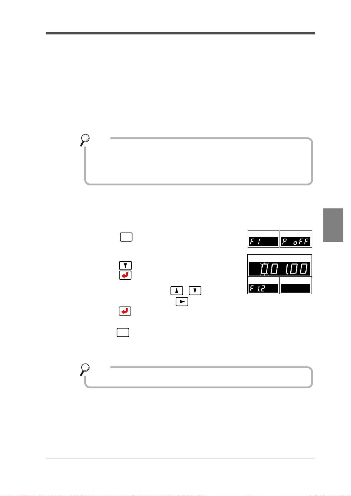
6-4. Near Zero
Near Zero ON/OFF is closely related to the SI/F print (stable value) function and
calculation comparison timing.
For details, see "6-5. Calculation comparison timing" on page 48, and "■ SI/F
print" on page 62.
Point
Ch
1
Ch 2
H
I
LO
H
I
LO
FNC
H
I
Ch
1
Ch 2
OK
LO
PEAK
HOLD
H
I
LO
H
I
LO
ESC
Near Zero operates by absolute value.
Point
This function is to detect that the indicated value (calculated value) is Near Zero.
Near Zero ON: |Calculated value| ≦ Setting value of Near Zero
Near Zero OFFF: |Calculated value| > Setting value of Near Zero
≪Setting value≫
0~99999
6 EXPLANATION OF COMPARISON FUNCTIONS
■Near Zero setting method
Select setting mode1.
1.
Press once.
2. Set "Near Zero."
Press twice ⇒ "Near Zero" is displayed.
Press , and the highest digit blinks.
Input the setting value with .
Move to the lower digits with .(Initial value:100)
Press to validate it.
3. Press twice to go back to the indicated value display.
Chapter
6
47
EXPLANATION OF COMPARISON FUNCTIONS
47

6 EXPLANATION OF COMPARISON FUNCTIONS
Ch
1
Ch 2
H
I
LO
H
I
LO
FNC
H
I
Ch
1
Ch 2
OK
LO
PEAK
HOLD
H
I
LO
H
I
LO
Undefined
Calculation comparison OK
0 0 0 0
Calculation comparison timing
Undefined
0:All time
1:Stable
2:Near Zero OFF
3:Stable and Near Zero OFF
4: Hold
output condition
ESC
6-5. Calculation comparison timing
Set the operating conditions of calculation HI/LO limit comparison. Select the conditions from the
following.
0:All time HI/LO limit comparison is always performed.
1:Stable HI/LO limit comparison is performed when the calculated
value is stable.
2:Near Zero OFF HI/LO limit comparison is performed when Near Zero is
off.
3:Stable and Near Zero OFF HI/LO limit comparison is performed when the calculated
value is stable and Near Zero is off.
4:Hold HI/LO limit comparison is performed when a hold is
fixed.
■Calculation comparison timing setting method
Chapter
6
EXPLANATION OF COMPARISON FUNCTIONS
1.
Select setting mode1.
Press once.
2. Set "Calculation comparison timing."
Press once. ⇒ "Calculation function
select" is displayed.
Press , and the highest digit blinks.
Input the setting value with .
(Initial value:0)
Press to validate it.
3. Press twice to go back to the indicated
value display.
48
48

6 EXPLANATION OF COMPARISON FUNCTIONS
Ch
1
Ch 2
H
I
LO
H
I
LO
FNC
H
I
Ch
1
Ch 2
OK
LO
PEAK
HOLD
H
I
LO
H
I
LO
H
I
Ch
1
Ch 2
OK
LO
PEAK
HOLD
HILO
H
I
LO
Undefined
Calculation comparison timing
0 0 0 0
Calculation comparison OK
Undefined
0:Calculated value only
1:Calculated value & ch1
2:Calculated value & ch2
3:Calculated value & ch1 & ch2
output conditions
ESC
6-6. Comparison OK output conditions
Conditions to turn on the external output "Calculation OK output" can be set.
0:Calculated value only The output turns on when calculation HI limit/LO
limit is off.
1: Calculated value & ch1 The output turns on when calculation HI limit/LO
limit and ch1 HI limit/LO limit are all off.
2:Calculated value & ch2 The output turns on when calculation HI limit/LO
limit and ch2 HI limit/LO limit are all off.
3:Calculated value & ch1 & ch2 The output turns on when calculation HI limit/LO
limit, ch1 HI limit/LO limit, and ch2 HI limit/LO limit
are all off.
■Comparison OK output conditions setting method
Select setting mode1.
1.
Press once.
2. Set "Comparison OK output conditions setting ."
Press once. ⇒ "Calculation function select"
is displayed.
Press , and the highest digit blinks.
Press once, and the lower digits blinks.
Input the setting value with .
(Initial value:0)
Press to validate it.
Chapter
6
3. Press twice to go back to the indicated
value display.
49
EXPLANATION OF COMPARISON FUNCTIONS
49

7 EXPLANATION OF HOLD FUNCTIONS
7 EXPLANATION OF
HOLD FUNCTIONS
7-1. Hold functions of calculated values
The hold functions are to take out a specific point of calculated values for HI/LO limit comparison.
Here, the operation of each hold will be described in detail.
Hold mode Hold section
0:OFF
1:Sample 0:All section 1:External signal
2:Peak
4:Average
■Flow of hold measurement
Chapter
Select a hold you want to use.
1.
7
2. If the hold has the setting of section, set a section you want to use.
EXPLANATION OF HOLD FUNCTIONS
For details, see "7-3.Setting of hold section" on page 54.
3. Set the special setting value required for the hold used.
4. After confirmation of wiring, perform hold control by external input, and start
measurement.
None
0:All section 1:External signal 2:External signal+Time3:Bottom
50
50

7-2. Setting of hold mode
Ch
1
Ch 2
H
I
LO
H
I
LO
FNC
H
I
Ch
1
Ch 2
OK
LO
PEAK
HOLD
HILO
H
I
LO
Hold section
Hold mode
0 0 0 1
Calculation mode
Auto reset
《Setting value》
0:OFF
1: Sample
2: Peak
3: Bottom
4: Average
ESC
Indicated
t2
t3
t1
Internal caleulated value
Hold Section
Fixed
t
+
T/H
HI-LO Limit
Judging Output
H/E
OFF
ON
OFF
ON
OFF
ON
HOLD
OFF
ON
Button
HOLD
Statu s Displa y
PEAK
Stat us Dis play
ONBlink Blink
OFF
Val ue
■Hold mode setting method
1. Select setting mode 1.
Press once.
2. Set "Hold mode."
Press four times ⇒ "Calculation hold function
select " is displayed.
Press , and the highest digit blinks.
Move to the lower digits with .
Input the setting value with .
(Initial value:0001)
Validate it with .
7 EXPLANATION OF HOLD FUNCTIONS
51
3. Press twice to go back to the indicated value
■Sample hold
The start point of the specified section is held.
The section is specified by the setting of "all section" or "external signal."
(Example) All section sample hold
display.
Chapter
7
t1: A delay time between the instant
when the T/H signal is inputted and the
instant when the indicated value is held
Approximately 0.7ms (MAX.)
t2: A delay time between the instant
when the T/H signal is released and the
instant
when the indicated value returns to
tracking
Approximately 0.7ms (MAX.)
t3: A minimum reset signal width
required for releasing the hold
Approximately 0.7ms (MIN.)
The delay time and signal width
expressed apply when the A/D
conversion speed is 3000 times/sec.
They become 10-times when the A/D
conversion speed is 300 times/sec.
51
EXPLANATION OF HOLD FUNCTIONS

7 EXPLANATION OF HOLD FUNCTIONS
Indicated value
t3
Internal calculated
Detection
t
+
T/H
HI-LO Limit
Judging Output
H/E
Hold Section
t2
t1
Fixed
SECTION
OFF
ON
OFF
ON
OFF
ON
OFF
ON
OFF
ON
ON
Blink ON
OFF ON
OFF
OFF
OFF
HOLD
Button
HOLD
Status Display
PEAK
Status Display
value
Indicated
t2
t3
Internal calculated
Detection・Hold Section
Undetermind
t
+
T/H
HI-LO Limit
Judging Output
H/E
Detection・Hold Section
t1t2t1
t3
OFF
ON
OFF
ON
OFF
ON
OFF
ON
HOLD
Status Display
PEAK
Status Display
ON
Blink Blink
OFF ON
OFF
OFF
OFF
OFF
OFF
HOLD
Button
Section (Note)
Undetermind
Section (Note)
Val ue
value
■Peak hold
The maximum value in the positive direction (peak value) of the specified section is held.
The section is specified by the setting of "all section," "external signal," or "external signal + time."
(Example) Externally specified section peak hold
t1: A delay time between the instant
when the SECTION signal is inputted
and the instant when the value to be
held is detected
Approximately 0.7ms (MAX.)
t2: A delay time between the instant
when the SECTION signal is released
and the instant when the value to be
held is determined
Approximately 0.7ms (MAX.)
t3: A minimum reset signal width
required for releasing the hold
Approximately 0.7ms (MIN.)
The delay time and signal width
expressed apply when the A/D
conversion speed is 3000 times/sec.
They become 10-times when the A/D
conversion speed is 300 times/sec.
■Bottom hold
Chapter
7
EXPLANATION OF HOLD FUNCTIONS
52
52
The maximum value in the negative direction (bottom value) of the specified section is held.
The section is specified by the setting of "all section," "external signal," or "external signal + time."
(Example) All section Bottom hold
Note: During the undetermined section, the judging output varies with fluctuations in the input waveform.
However, the H/E output remains on during the undetermined section. Read the judging result when the
indicated value becomes stable (immediately before the T/H signal rises).
t1: A delay time between the instant
when the T/H signal is inputted and
the instant when the indicated value
is held
Approximately 0.7ms (MAX.)
t2: A delay time between the instant
when the T/H signal is released and
the instant
when the indicated value returns to
tracking
Approximately 0.7ms (MAX.)
t3: A minimum reset signal width
required for releasing the hold
Approximately 0.7ms (MIN.)
The delay time and signal width
expressed apply when the A/D
conversion speed is 3000 times/sec.
They become 10-times when the A/D
conversion speed is 300 times/sec.

7 EXPLANATION OF HOLD FUNCTIONS
Internal calculated value
Hold Value
t
+
T/H
Limit Judging
H/E
Fixed
SECTION
OFF
ON
OFF
ON
OFF
ON
OFF
ON
Undetermind
t1 t2 t3
Detection Hold Sect ion
OFF
ON
HOLD
Button
HI-LO
HOLD
Status Display
PEAK
Status Display
ON
Blink ON
OFF ON OFF
OFF
OFF
Section (Note)
Output
■Average hold
The average of the sampling values over the specified section is calculated and updated, and then
held.
The section is specified by the setting of "all section," "external signal," or "external signal + time."
(Example) Externally specified section average value hold
t1: A delay time between the instant
when the SECTION signal is inputted
and the instant when the value to be held
is detected
Approximately 0.7ms (MAX.)
t2: A delay time between the instant
when the SECTION signal is released
and the instant when the value to be held
is determined
Approximately 0.7ms (MAX.)
t3: A minimum reset signal width
required for releasing the hold
Approximately 0.7ms (MIN.)
The delay time and signal width
expressed apply when the A/D
conversion speed is 3000 times/sec.
They become 10-times when the A/D
conversion speed is 300 times/sec.
The detection section is limited by the maximum average value detection time set according to the
Chapter
"average sample number." If the maximum average value detection time is exceeded, detection is
automatically terminated, and the average value of that time is held.
7
■Average sample number
In the average hold, the maximum average value detection time for average processing by each
sampling depends on the A/D conversion speed as follows:
When the A/D conversion speed is 300 times/sec: 50sec.
When the A/D conversion speed is 3000 times/sec: 5sec.
Then, if this average sample number is set at 2 or more, the sampling data used for average
calculation becomes the representative value of the sampling values of the set number (average
obtained according to the number). By this setting, the average value detection time can be
elongated, but error causes by average calculation increase.
Example) When the A/D conversion speed is 3000 times/sec,
Maximum average value detection time = Average sample number × 10 sec.,
and also the number of average updates will decrease.
Number of average updates = 3000 times/sec. ÷ Average sample number
≪Setting value≫
53
1~999 [times]
EXPLANATION OF HOLD FUNCTIONS
53

7 EXPLANATION OF HOLD FUNCTIONS
Ch
1
Ch 2
H
I
LO
H
I
LO
FNC
H
I
Ch
1
Ch 2
OK
LO
PEAK
HOLD
H
I
LO
H
I
LO
ESC
Ch
1
Ch 2
H
I
LO
H
I
LO
FNC
H
I
Ch
1
Ch 2
OK
LO
PEAK
HOLD
HILO
H
I
LO
Hold section
Hold mode
0 0 0 1
Calculation mode
Auto reset
0: All section
1: External signal
2: External signal + time
* This setting is required only
than "0: OFF."
when the hold mode is other
ESC
◇Average sample number setting method
1. Select setting mode 1.
Press once.
2. Set "Average sample number."
Press six times ⇒ "Average sample number "
is displayed.
Press , and the highest digit blinks.
Input the setting value with . (Initial value:1)
Move to the lower digits with .
Press to validate it.
3. Press twice to go back to the indicated value display.
7-3. Setting of hold section
■Hold section setting method
Chapter
7
EXPLANATION OF HOLD FUNCTIONS
Select setting mode 1.
1.
Press once.
2. Set "Hold section."
Press four times ⇒ "Calculation hold function
select " is displayed.
Press , and the highest digit blinks.
Press twice to make the digit of the Hold
section blink. (Initial value: 0001)
Input the setting value with .
Press to validate it.
3. Press twice to go back to the indicated value
display.
54
54

7 EXPLANATION OF HOLD FUNCTIONS
Indicated value
t2
t3
Internal caluculated value
Detection
・
Hold Section
Undetermind
t
+
T/H
HI-LO Limit
Judging Output
H/E
Detection・Hold Section
t1
t2t1
t3
Undetermind
OFF
ON
OFF
ON
OFF
ON
OFF
ON
HOLD
Status Display
PEAK
Status Display
ON
Blink Blink
OFF ON
OFF
OFF
OFF
OFF
OFF
HOLD
Button
Section(Note)
Section(Note)
■All section
By this method, the hold detection section is specified by the T/H signal.
Detection starts with the T/H signal ON to perform each hold operation.
Control is performed simply by the T/H signal without using the SECTION signal.
Therefore, there are tracking sections and detection sections, but there are no hold deciding
sections.
(Example) All section peak hold
t1: A delay time between the instant
when the T/H signal is inputted and
the instant when the indicated value
is held
Approximately 0.7ms (MAX.)
t2: A delay time between the instant
when the T/H signal is released and
the instant
when the indicated value returns to
tracking
Approximately 0.7ms (MAX.)
t3: A minimum reset signal width
required for releasing the hold
Approximately 0.7ms (MIN.)
The delay time and signal width
expressed apply when the A/D
conversion speed is 3000 times/sec.
They become 10-times when the A/
D conversion speed is 300 times/sec.
Note:During the undetermined sections, the judging output varies with fluctuations in the input waveform.
However, the H/E output remains on during the undetermined sections. Read the judging result when
the indicated value becomes stable (immediately before the T/H signal rises).
Chapter
7
55
EXPLANATION OF HOLD FUNCTIONS
55

7 EXPLANATION OF HOLD FUNCTIONS
Indicated value
t3
Internal calculated
Detection
t
+
T/H
HI-LO Limit
Judging Output
H/E
Hold Section
t2
t1
Fixed
SECTION
OFF
ON
OFF
ON
OFF
ON
OFF
ON
OFF
ON
ON
Blink ON
OFF ON
OFF
OFF
OFF
HOLD
Button
HOLD
Status Display
PEAK
Status Display
value
■External signal
By this method, the hold detection section is specified by the SECTION signal.
Detection starts with the SECTION signal ON, and ends with the SECTION signal OFF to perform
each hold operation.
The hold value is maintained until the hold reset signal is turned on.
The hold is released by turning on the T/H signal as a reset signal.
There are tracking sections, detection sections, and hold deciding sections.
tant when the T/H signal is turned on.
(Example) Externally specified section peak hold
t1: A delay time between the instant
when the SECTION signal is inputted
and the instant when the value to be
held is detected
Approximately 0.7ms (MAX.)
t2: A delay time between the instant
when the SECTION signal is released
and the instant when the value to be
held is determined
Approximately 0.7ms (MAX.)
Chapter
7
EXPLANATION OF HOLD FUNCTIONS
again without turning on the T/H signal while the hold is fixed, the hold is released and re-
detection is started. For details, see "7-4.Auto reset function" on page 58.
t3: A minimum reset signal width
required for releasing the hold
Approximately 0.7ms (MIN.)
The delay time and signal width
expressed apply when the A/D
conversion speed is 3000 times/sec.
They become 10-times when the A/D
conversion speed is 300 times/sec.
By turning on the SECTION signal
56
56

7 EXPLANATION OF HOLD FUNCTIONS
Indicated value
t3
Internal calculatde value
Detection
t
+
HI-LO Limit
Judging Output
H/E
Hold Section
t2
t1
Fixed
SECTION
T/H
OFF
ON
OFF
ON
OFF
ON
OFF
ON
OFF
ON
OFF
ON
ON
Blink ON
OFF ON
OFF
OFF
OFF
HOLD
Button
Detection time
HOLD
Status Display
PEAK
Status Display
Ch
1
Ch 2
H
I
LO
H
I
LO
FNC
H
I
Ch
1
Ch 2
OK
LO
PEAK
HOLD
HILO
H
I
LO
ESC
■External signal + time
By this method, the hold detection section is specified as a timer. Detection starts with the
SECTION signal ON, and ends when the set time (detection time) has elapsed.
The hold value is maintained until the hold reset signal is turned on.
The hold is released by turning on the T/H signal as a reset signal.
There are tracking sections, detection sections, and hold deciding sections.
(Example) External signal+ Time specified section peak hold
t1: A minimum SECTION signal width
required for beginning detection
Approximately 0.7ms (MIN.)
t2: A delay time between the instant
when the detection time is ended and
the instant when the value to be held is
determined
Approximately 0.7ms (MAX.)
t3: A minimum reset signal width
required for releasing the hold
Approximately 0.7ms (MIN.)
57
By turning on the SECTION signal again without turning on the T/H signal while the hold is
fixed, the hold is released and re-detection is started.
For details, see "7-4.Auto reset function" on page 58.
■Detection time
Set the hold detection time.
《Setting value》
0.01~9.99 [sec.]
◇ Detection time setting method
1. Select setting mode 1.
Press once.
2. Set "Detection time."
Press five times ⇒ "Detection time" is displayed.
Press , and the highest digit blinks.
Move to the lower digits with .(Initial value:1)
Input the setting value with .
Press to validate it.
3. Press twice to go back to the indicated value display.
The delay time and signal width
expressed apply when the A/D
conversion speed is 3000 times/sec.
They become 10-times when the A/D
conversion speed is 300 times/sec.
Chapter
7
EXPLANATION OF HOLD FUNCTIONS
57

7 EXPLANATION OF HOLD FUNCTIONS
SECTION
T/H
H/E
Example) Auto reset in externally specified section peak hold
Upon turning-ON of the SECTION signal,
hold reset is performed and detection starts.
Control can be performed without inputting the T/H
signal.
However, a hold value is maintained until the
SECTION signal turns ON.
When auto reset is on in externally
SECTION
H/E
T/H
When auto reset is off in externally
SECTION
H/E
T/H
SECTION
H/E
T/H
SECTION
H/E
T/H
When auto reset is on in externally
When auto reset is off in externally
If the SECTION signal
chatters, the point shifts
from the proper one.
The first hold value is
maintained until T/H is
inputted.
If the SECTION signal
chatters, the point shifts from
the proper one.
The first hold value is
maintained until T/H is
inputted.
specified section sample hold
specified section peak hold
specified section peak hold
specified section sample hold
7-4. Auto reset function
It is factory-set that each hold is automatically reset at the start of the detection section, and
therefore, simple control can be performed by one signal without releasing the hold.
However, when the auto reset functions, if the signal causes chattering, the point that should be
taken originally may deviate. Switching is provided so as to prevent the next detection from being
performed until the T/H signal is turned on even if the SECTION signal is turned on again.
《Setting value》
0:OFF After a hold is fixed, the next detection is not started until the T/H
signal is turned on even if the SECTION signal is turned on.
Chapter
7
1:ON After a hold is fixed, the next detection is started when the SECTION
signal is turned on again even if the T/H signal is not turned on. This is
the initial setting (factory default setting).
EXPLANATION OF HOLD FUNCTIONS
58
58

■Auto reset setting method
Ch
1
Ch 2
H
I
LO
HILO
FNC
H
I
Ch
1
Ch 2
OK
LO
PEAK
HOLD
H
I
LO
H
I
LO
Hold section
Hold mode
0 0 0 1
Calculation mode
Auto reset
《Setting value》
0:OFF
1:ON
* This setting is required when the
hold section is "external signal"
or "external signal + time."
ESC
Select setting mode 1.
1.
Press once.
2. Set "Auto reset."
Press four times ⇒ "Calculation hold
function select " is displayed.
Press , and the highest digit blinks.
Press three times to make the digit of
the auto reset blink. (Initial value: 0001)
Input the setting value with .
Press to validate it.
3. Press twice to go back to the
indicated value display.
7 EXPLANATION OF HOLD FUNCTIONS
Chapter
7
EXPLANATION OF HOLD FUNCTIONS
59
59

8 STANDARD INTERFACE
8 STANDARD INTERFACE
8-1. External I/O
■Connector pin assignment
A1 COM1 B1 COM1
A2 OUT HI(Calculated) B2 OUT ALM(ch2)
A3 OUT OK(Calculated) B3 OUT H/E
A4 OUT LO(Calculated) B4 OUT
A5 OUT HI(ch1) B5 OUT
A6 OUT LO(ch1) B6 OUT RUN
A7 COM1 B7 COM2
Chapter
8
STANDARD INTERFACE
A8 OUT ALM(ch1) B8 IN SECTION
A9 OUT HI(ch2) B9 IN T/H
A10 OUT LO(ch2) B10 IN
A11 OUT SI/F B11 IN D/Z-1
A12 OUT SI/F B12 IN D/Z-2
Compatible connector: FCN-361J024-AU(manufactured by FUJITSU COMPONENT or equivalent)
Connector cover: FCN-360C024-B(manufactured by FUJITSU COMPONENT or equivalent)
(connector & cover optional type: CN50)
■About outputs
A1, A7, B1 Common for external output signals.
A2 Outputs the calculated value HI limit signal.
A3 Outputs the calculated value OK signal.
A4 Outputs the calculated value LO limit signal.
A5 Outputs the ch1 value HI limit signal.
A6 Outputs the ch1 value LO limit signal.
→
" ■ External I/O connection " on page 14
"6. EXPLANATION OF COMPARISON
→
FUNCTIONS " on page 44
A8 Outputs the ch1 value alarm signal.
A9 Outputs the ch2 value HI limit signal.
A10 Outputs the ch2 value LO limit signal.
B2 Outputs the ch2 alarm signal.
B3 Outputs the hold complete signal.
B6 Outputs the normal run signal.
→
"4. CALIBRATION PROCEDURE " on page 23
→ "6. EXPLANATION OF COMPARISON
FUNCTIONS " on page 44
→
"4. CALIBRATION PROCEDURE " on page 23
"7. EXPLANATION OF HOLD FUNCTIONS "
→
on page 50
→
" ■ About the RUN signal " on page 61
60
60

8 STANDARD INTERFACE
Refer to "11-7. Error/message list " on page 97 about the
contents of errors.
OFF
RUN
ON
OFF
RUN
ON
0.5sec. pulse
3.0sec.
Error factor removal
This signal turns off when an error occurs.
duty50%
* By the error factor removal, ON-OFF operation restarts in 3.0 sec.
* RUN turns off when the power is turned off.
A11, A12
2-wire serial interface for connecting a
UNIPULSE-manufactured printer, external
display, etc.
" ■ SI/F interface connection " on page 15
→
"8-2 SI/F(Serial interface) " on page 62
■About inputs
B7 Common for external input signals.
B8, B9 Inputs the hold control signal.
B11, B12 Inputs the Digital Zero signal.
→
" ■ External I/O connection " on page 14
"7. EXPLANATION OF HOLD
→
FUNCTIONS " on page 50
→
"5-4. Digital Zero " on page 38
■About the RUN signal
The RUN output stops when an abnormal state of the indicated value is detected. The conditions
under which the output stops as in an abnormal state are as follows.
・±LOAD
・OFL1, OFL2
・Calibration error
・Digital Zero limit error
Chapter
8
STANDARD INTERFACE
61
61

8 STANDARD INTERFACE
Ch
1
Ch 2
H
I
LO
H
I
LO
FNC
H
I
Ch
1
Ch 2
OK
LO
PEAK
HOLD
H
I
LO
H
I
LO
000
Undefined
SI/F print
SI/F Indicated value
0: Calculated value
1: Calculated value
2:ch1/ch2
《Setting value》
/ch1
/ch2
format
ESC
8-2. SI/F(Serial interface)
■SI/F Indicated value format
For the SI/F, indicated value data exist in two areas: GROSS area and NET area.
Select the data.
《Setting value》
0:Calculated value/ch1 value GROSS area:calculated value NET area:ch1 value
1:Calculated value/ch2 value GROSS area: calculated value NET area: ch2 value
2:ch1 value/ch2 value GROSS area: ch1 value NET area: ch2 value
◇SI/F Indicated value format setting method
1. Select setting mode 2.
Press → once.
Chapter
8
STANDARD INTERFACE
62
■SI/F print
62
2. Set "SI/F Indicated value format."
Press twice ⇒ "SI/F function select " is
displayed.
Press , and the highest digit blinks.
Press once to make the digit of the SI/F
function select blink.
Input the setting value with .
(Initial value:0)
Press to validate it.
3. Press twice to go back to the indicated value
display.
《Setting value》
0: None No print command is sent.
1:Stable value When stability of the calculated value is detected, a print command
2:Hold value When hold is reset, a print command is sent to make the connected
Also, not-held calculated values are taken in the NET area.
is sent to the SI/F to make the connected printer print automatically.
When Near Zero is OFF, the calculated value is held until Near Zero
ON after stable ON.
Hold is reset in 1.5 sec. after Near Zero ON.
printer print the hold value automatically. In this case, the hold value
is forcedly taken in the GROSS area in sending.

◇SI/F print setting method
When stable value print is selected, be aware that automatic printing is not
performed in the following case.
・When Motion Detect is set in time: 0.0 sec, count: 00.
Also, the indicated value is not held in the following case.
・Hold mode: When any item other than none is selected.
Point
Ch
1
Ch 2
HILO
H
I
LO
FNC
SI/F print
0: None
H
I
Ch
1
Ch 2
OK
LO
PEAK
HOLD
H
I
LO
H
I
LO
000
Undefined
1:Stable value
SI00/F Indicated value
2:Hold value
《Setting value》
format
ESC
Indicated value
Near Zero
0
Stable
Near Zero
ON
ON
ONON
OFF
OFF
OFF
Automatic printing
↑
Hold
1.5seconds
Time
ON
*Hold function …
Indicated value
SI/F
Comparison output signal
+
Internal calculated value
Near Zero
0
Time
Stab le
Near Zero
ON
ON
ONON
OFF
OFF
OFF
Automatic printing
↑
Hold
1.5seconds
ON
-
Indicated
Internal calculated value
value
1. Select setting mode 2.
Press → once.
2. Set "SI/F print."
Press twice ⇒ "SI/F function select" is
displayed.
Press , and the highest digit blinks. Select the
digit of the SI/F print.
8 STANDARD INTERFACE
Input the setting value with .
(Initial value:0)
Press to validate it.
3. Press twice to go back to the indicated value
display.
Chapter
・Operation of the indicated value hold function
8
STANDARD INTERFACE
63
For the "Stable" parameter, see "5-7. Motion Detect " on page 41, and for the "Near Zero"
parameter, see "6-4. Near Zero " on page 47.
63

9 OPTION INTERFACE
9 OPTION INTERFACE
BCD data output
connector
● Internal transistor status
Output data Negative Positive
0OFFON
1ONOFF
Vceo=30V(max)
● Output pin level
Output data Negative Positive
0HL
1LH
Through logic switching (pin B14)
Vcc +5V
COM
Ic =30mA (max)
Inside
outside
Vext
F350
9-1. BCD interface
The BCD data output is an interface to extract the indicated value of the F350 as BCD data. This
interface is convenient to process controls, totals, records, etc., by connecting the F350 to a
computer, process controller, sequencer or the like.
The I/O and internal circuits are electrically insulated by photocoupler.
Chapter
9
OPTION INTERFACE
■Connection
●Output
The signal output circuit employs the TTL open collector output.
64
64

●Input
Transistor
TTL open collector output
Open OFF
Short ON
Vcc
+5V
IC=Approx.6mA
COM
Switch
Inside
Outside
F350
(ON when IN is HI)
CAUTION
● Do not apply external voltage to the signal input circuit.
The external element is required to withstand Ic=10mA.
●
Leakage from the external element is required to be 30μA or below
●
9 OPTION INTERFACE
.
■Connector pin assignment
A1
A2
A3
A4
A5
A6
A7
A8
A9
A10
A11
A12
A13
A14
A15
A16
*
OUT
OUT
OUT
OUT
OUT
OUT
OUT
OUT
OUT
OUT
OUT
OUT
IN
IN
-
COM
1 B2
2 B3
4 B4
8 B5
10 B6
20 B7
40 B8
80 B9
100 B10
200 B11
400 B12
800 B13
Data Hold B14
Data Switching 0 B15
B1
B16
*
OUT
OUT
OUT
OUT
OUT
OUT
OUT
OUT
OUT
OUT
OUT
OUT
IN
IN
-
COM
1000
2000
4000
8000
10000
20000
40000
80000
Minus (Polarity)
OVER
STAB
STROBE
Logic Switching
Data Switching 1
Chapter
9
OPTION INTERFACE
65
Compatible connector: FCN-361J032-AU (manufactured by FUJITSU COMPONENT or equivalent)
Connector cover: FCN-360C032-B (manufactured by FUJITSU COMPONENT or equivalent)
(connector & cover optional type: CN51)
65

9 OPTION INTERFACE
Ch 2
HILO
Ch
1
H
I
LO
FNC
H
I
Ch
1
Ch 2
OK
LO
PEAK
HOLD
HILO
HILO
ESC
■Output data select
《Setting value》
0:Calculated value The calculated value is output.
1:ch1 value The ch1 value is output.
2:ch2 value The ch2 value is output.
3:External select Data selected by the data select input (A15, B15) is output.
Data select 1 Data select 0 Output data
OFF OFF
OFF ON ch1 value
ON OFF ch2 value
ON ON
* In the case of external selection, read after at least 2 cycles.
◇ Output data select setting method
1. Select setting mode 5.
Press → four times.
2. Set "Output data select."
Press once. ⇒ "Output data select" is displayed.
Press once, and present set value blinks.
Input the setting value with .
(Initial value:0)
Press to validate it.
Calculated value
(hold synchronized)
Calculated value
(hold not synchronized)
Chapter
9
OPTION INTERFACE
66
3. Press twice to go back to the indicated value display.
■Signal timing
● Minus Turns on when the output indicated value data is negative.
● OVER Turns on at over-scale time.
-LOAD、+LOAD、OFL1、OFL2
● STAB Turns on at stable-time. See "5-7. Motion Detect" on page 41.
● STROBE Strobe pulses are output in synchronization with BCD data.
For reading the data, use the rising edges of the pulses when the
logic is negative, and the falling edges of the pulses when the logic
is positive.
66

■Logic switching
BCD data
OVER
Strobe range
STROBE
0
1
0
1
STAB
(duty 50%)
Update
BCD data
OFF
ON
BCD
1cycle
1cycle(max)
Updating is stopped.
0
1
STROBE
data hold
9 OPTION INTERFACE
Select the logic of the BCD data output signal. Make selection with B14.
When COM and B14 are open :Negative logic
When COM and B14 are short-circuited :Positive logic
Read at least 2 cycles after inputting the logic switching.
■BCD data hold
Updating of the BCD data output signal is stopped. Also, the STROBE output turns OFF.
Make selection with A14.
When COM and A14 are open :Update stop canceled
When COM and A14 are short-circuited :Update stopped
Chapter
9
67
Read at least 2 cycles after inputting the BCD data hold.
As long as the BCD data hold is input, data can be read reliably, but because the data is not updated,
OPTION INTERFACE
it may be different from original data.
67

9 OPTION INTERFACE
Even if this setting is changed, A/D conversions speed does not change.
Make the output rate slower when reading fails due to a low processing
performance of the device that should receive BCD.
Point
Ch 2
H
I
LO
Ch
1
H
I
LO
FNC
H
I
Ch
1
Ch 2
OK
LO
PEAK
HOLD
H
I
LO
H
I
LO
ESC
■Output rate
《Setting value》
0:10 4:300
1:30 5:500
2:50 6:1000
3:100 【times/sec.】
* When the A/D conversion speed is 300 times/sec., settings are available up to 4: 300
[times/sec.].
◇Output rate setting method
Chapter
9
OPTION INTERFACE
1. Select setting mode 5.
Press → four times.
2. Set "Output rate."
Press Twice. ⇒ "Output rate" is displayed.
Press , and present set value blinks.
Input the setting value with .
(Initial value:3)
Press to validate it.
3. Press twice to go back to the indicated value display.
■BCD/binary select
The output data selection can be changed to binary.
《Setting value》
0:BCD
1:Binary
68
68

◇BCD/binary setting method
Ch 2
HILO
Ch
1
HILO
FNC
H
I
Ch
1
Ch 2
OK
LO
PEAK
HOLD
H
I
LO
H
I
LO
ESC
1. Select setting mode 5.
Press → four times.
2. Select "BCD/binary select."
Press three times. ⇒ "BCD/binary select" is
displayed.
Press , and present set value blinks.
Input the setting value with .
(Initial value:0)
Press to validate it.
3. Press twice to go back to the indicated value display.
9 OPTION INTERFACE
■Pin assignment at binary
A1
A2
A3
A4
A5
A6
A7
A8
A9
A10
A11
A12
*
OUT
OUT
OUT
OUT
OUT
OUT
OUT
OUT
OUT
OUT
OUT
COM
0
2
1
2
2
2
3
2
4
2
5
2
6
2
7
2
8
2
9
2
10
2
B1
B2
B3
B4
B5
B6
B7
B8
B9
B10
B11
B12
*
OUT
OUT
OUT
OUT
OUT
OUT
OUT
OUT
OUT
OUT
OUT
COM
12
2
13
2
14
2
15
2
16
2
Data Switching 0
(Response)
Data Switching 1
(Response)
Minus (Polarity)
OVER
STAB
Chapter
9
A13
A14
A15
A16
OUT
IN
IN
-
Data Switching 0 B15
11
2
B13
Data Hold B14
B16
OUT
IN
IN
-
STROBE
Logic Switching
Data Switching1
OPTION INTERFACE
* With the B8 and B9 outputs, the data specified by the output data selection or
by A15 and B15 (data select) can be checked.
69
69

9 OPTION INTERFACE
9-2. RS-232C interface
The RS-232C is an interface to read the indicated value and status of the F350 and to write
parameters into the F350.
This interface is convenient to process controls, totals, records, etc., by connecting the F350 to a
computer, process controller, sequencer or the like.
■Communication specifications
Signal level: Based on RS-232C
Transmitting distance: Approx.15m
Transmitting method: Asynchronous,Full duplex
Baud rate: 9600, 19200, 38400, 57600bps Selectable
Bit configuration: Start bit: 1bit
Character length: 7 or 8 bit Selectable
Stop bit: 1 or 2 bit Selectable
Parity : Parity none,odd or even Selectable
Delimiter: CR, CR+LFSelectable
Chapter
9
OPTION INTERFACE
Code: ASCII
■Connector pin assignment
1
2
3
4
5
6
7
8
9
Case
Adaptable connector 9-pin D-SUB connector
-
IN
OUT
OUT
*
-
OUT
IN
-
*
Connector: XM3D-0921(Omron) or equivalent
Cover: XM2S-0913(with inch screw thread #4-40)(Omron) or equivalent
(connector & cover optional type: CN34)
RXD
TXD
DTR
GND
RTS
CTS
SHIELD
70
70

■Connection
Ch 2
H
I
LO
Ch
1
H
I
LO
FNC
H
I
Ch
1
Ch 2
OK
LO
PEAK
HOLD
H
I
LO
H
I
LO
ESC
9 OPTION INTERFACE
Example)F350
XM3D-0921 or equivalent
PC etc.
D-sub9pin
1 1CD
2RXD 2RXD
3TXD 3TXD
4DTR 4DTR
5GND 5GND
6 6DSR
7RTS 7RTS
8CTS 8CTS
9 9RI
* This connection diagram shows cabling applicable to the case where your PC is DTE (data
terminal equipment). For connection with DCE (data circuit-terminating equipment), such as a
modem, use straight type cabling.
* Prepare cabling after reconfirmation of the connector shape and signal lines (pin assignments) of
the equipment you use.
■Communication mode
《Setting value》
0:Send/receive
This mode performs communication by a command from the host computer.
In this mode, you can read out the indicated value, status, set values and write in
set values.
1:Continuous send
This mode continuously transmits the indicated values and the status.
2:Print send mode
When the indicated value is printed (a print command is output to the SI/F), the
indicated value and status are sent from the F350 to host.
◇Communication mode setting method
1. Select setting mode 5.
Press → four times.
2. Set "Communication mode."
Press once. ⇒ "Communication mode" is
displayed.
Chapter
9
Press , and present set value blinks.
Input the setting value with .(Initial value:0)
OPTION INTERFACE
Press to validate it.
3. Press twice to go back to the indicated value display.
71
71

9 OPTION INTERFACE
Ch 2
H
I
LO
Ch
1
H
I
LO
FNC
H
I
Ch
1
Ch 2
OK
LO
PEAK
HOLD
H
I
LO
H
I
LO
Baud rate
0:9600 bps 2:38400 bps
111 00
Flow control
0: None 1:RTS/CTS
Character length
0:7bit 1:8bit
Parity bit
0: None 1: Even 2: Odd
Stop bit
0:1bit 1:2bit
1:19200 bps 3:57600 bps
ESC
Ch 2
H
I
LO
Ch
1
H
I
LO
FNC
H
I
Ch
1
Ch 2
OK
LO
PEAK
HOLD
H
I
LO
H
I
LO
ESC
■Communication conditions
Set the communication conditions according to the host.
◇Communication conditions setting method
1. Select setting mode 5.
Press → four times.
2. Set "Communication conditions."
Press twice. ⇒ "Communication
conditions" is displayed.
Press , and present set value blinks.
Input the setting value with .
(Initial value:11100)
Move to the lower digits with .
Press to validate it.
Chapter
9
OPTION INTERFACE
3. Press twice to go back to the indicated
value display.
■Delimiter
Set the delimiter for sending messages from the F350.
《Setting value》
0:CR
1:CR+LF
◇Delimiter setting method
1. Select setting mode 5.
Press → four times.
72
72
2. Set "Delimiter."
Press three times. ⇒ "Delimiter" is displayed.
Press , and present set value blinks.
Input the setting value with .
(Initial value:11100)
Press to validate it.
3. Press twice to go back to the indicated value display.

■Communication format
R
.321+AR
CRA
54
Delimiter
Host
F350
Sign, decimal point, 5-digit indicated value.
R
.321+BR
CRB
54
Delimiter
Host
F350
Sign, decimal point, 5-digit indicated value.
R
.321+CR
CRC
54
Delimiter
Host
F350
Sign, decimal point, 5-digit indicated value.
R
00000DR
CRD
00
Delimiter
Host
F350
Hold
Stable
Near Zero
HI
OK
LO
0:OFF 1:ON
0:OFF 1:ON
0:OFF 1:ON
0:OFF 1:ON
0:OFF 1:ON
0:OFF 1:ON
Undefined
(Calculated value)
(Calculated value)
(Calculated value)
R
00000ER
CRE
00
Delimiter
Host
F350
HI(ch2)
0:OFF 1:ON
0:OFF 1:ON
0:OFF 1:ON
0:OFF 1:ON
0:OFF 1:ON
0:OFF 1:ON
Undefined
LO(ch1)
HI(ch1)
ALM(ch1)
LO(ch2)
ALM(ch2)
1.Send/receive [Reading the indicated value/status]
Function
Indicated value
(Calculated
value)
Header
Main Sub
RA
9 OPTION INTERFACE
Reading the indicated value/status
Protocol
Indicated value
(ch1)
Indicated value
(ch2)
Status1
(Calculated
value)
RB
RC
RD
Chapter
73
Status2
(ch1,ch2)
RE
9
OPTION INTERFACE
73

9 OPTION INTERFACE
R
00000FR
CRF
00
Delimiter
Host
F350
OFL2(ch1)
0:OFF 1:ON
0:OFF 1:ON
0:OFF 1:ON
0:OFF 1:ON
0:OFF 1:ON
Undefined
Undefined
+LOAD(ch1)
-LOAD(ch1)
OFL1(ch1)
cErr(ch1)
R
00000GR
CRG
00
Delimiter
Host
F350
OFL2(ch2)
0:OFF 1:ON
0:OFF 1:ON
0:OFF 1:ON
0:OFF 1:ON
0:OFF 1:ON
Undefined
Undefined
+LOAD(ch2)
-LOAD(ch2)
OFL1(ch2)
cErr(ch2)
R
.321+JR
CRJ
54
Delimiter
Host
F350
Sign, decimal point, 5-digit indicated value.
Function
Header
Main Sub
Reading the indicated value/status
Protocol
Status 3
(ch1)
Status 4
(ch2)
RF
RG
Chapter
9
OPTION INTERFACE
Indicated value
(Real time
Calculated
value)
74
74
RJ

2. Send/receive [Setting value writing/reading]
10000000W CR
Host
F350
* For a setting value with ch switching, make sure to write in advance the
command
1:ch1 2:ch2
Setting values without channel switching are disregarded.
channel number selected, and then write or read the setting value.
The command is fixed at 00.
0 fixation
00 fixation
4321+11W CR5
Host
F350
Sign, decimal point, 5-digit indicated value.command
* When the number of digits of the setting value is smaller than five, put a zero in the higher digit(s).
Example) 3 digits
2100+**W CR3
00000**W CR3
* For Motion Detect and Zero Tracking, put a zero in the 3rd digit.
10510**W CR0
Example)Time 1.5sec.
Range 10
(For a setting value with a decimal point, simply write
* When the setting value is unsigned, put a zero in the sign digit.
the numerical value excluding the decimal point.)
W
4321+11
11
5
Delimiter
Host
F350
CR
W
Sign, decimal point, 5-digit indicated value.command
(A setting value with a decimal point results in the numerical value excluding the decimal point.)
* The mode number of the setting value of HI/LO limit is "0."
* For setting mode numbers and setting item numbers, see "11-1.
The list of initial setting value" on page 88.
1 1
Setting value item number
Setting mode number (F*)
●"Setting protect" and "key protect" can be read but cannot be written.
●"Initialize" and "password" cannot be either read or written.
●When the protect of the setting value you are going to write is ON, it cannot be written. Turn OFF
the protect by key operation.
●If an output value is written in command 42 (zero calibration), simulated zero calibration is
executed with the written value. Also, if an output value is written in command 43 (equivalent input
calibration), equivalent input calibration is executed.
Point
Channel selection (Setting value with channel switching)
Function
Header
Main Sub
9 OPTION INTERFACE
Protocol
channel
switching
Function
Various
settings
Function
w
Main Sub
w
Main Sub
-
Header
-
Header
Setting value writing
Protocol
Setting value reading
Protocol
Various
settings
w
-
* Command definition
75
Chapter
9
OPTION INTERFACE
75

9 OPTION INTERFACE
C CRZ
Host
F350
C CRS
Host
F350
C CRE
Host
F350
C CRF
Host
F350
C CRG
Host
F350
C CRH
Host
F350
C CRI
Host
F350
C CR1
Host
F350
C CR2
Host
F350
C CR3
Host
F350
C CR4
Host
F350
●Give commands with channel switching after setting the channel by ch switching.
For details, see " 1.Send/receive [Reading the indicated value/status]" on page 73.
●If the calibration protect is ON, zero calibration and span calibration cannot be
performed.
Point
3. Send/receive[Command]
Function
Zero calibration
(with channel
switching)
Equivalent input
calibration
(with channel
switching)
Digital Zero
(simultaneous on both
channels)
Digital Zero reset
(simultaneous on both
channels)
Digital Zero
(with channel
switching)
Header
Main Sub
CZ
CS
CE
CF
CG
Movement directive
Protocol
Chapter
9
OPTION INTERFACE
Digital Zero reset
(with channel
CH
switching)
SI/F print command C I
SECTION
ON
SECTION
OFF
T/H
ON
T/H
OFF
C1
C2
C3
C4
76
76

4. Send/receive [Returning an error]
E *R
Host
F350
Delimiter
1: The command or message length is improper.
2: The protect of the setting value you are going to write
3: The format (whether or not to sign, the number of
4: Other communication errors (parity error, frame error, etc.)
value you are going to write is improper.
calibration protect is ON.
digits, other than the numerical value) of the setting
is ON, or a calibration command is received while the
50+,68.47 .1+ 1 ,32
1098765432121101
S8S7S6S5S4S3S2S1, ,S9
F350
G S
Delimiter54.32+ 1
ch2
Calculated value ch1
S1 S2 S3 S4 S5
S:Stab le
M:Not Stable
H:Calculated value
Hold
O:ch1
Over Load
(±LOAD、OFL1,2)
A : ch1 Alarm
C:ch1 Calibration
error
N:No error
O:ch2
Over Load
(±LOAD、OFL1,2)
A : ch2 Alarm
C:ch2 Calibration
error
N:No error
H:Calculated value
HI ON
L:Calculated value
LO ON
G:Calculated value
HI/LO OFF
N:Calculated value
HI/LO ON
F:Calculated
value Comparison
OFF
H:ch1 HI ON
L:ch1 LO ON
G:ch1 HI/LOOFF
N:ch1 HI/LOON
H>(SorM) O > A > C > NO> A > C > NN> (HorL) > F > GN> (HorL) > G
S6 S7 S8 S9
H:ch2 HI ON
L:ch2 LO ON
G:ch2 HI/LO OFF
N:ch2 HI/LO ON
N:Near Zero OFF
Z:Near Zero ON
A:ch1
Zero Tracking OFF
T:ch1
Zero Tracking ON
A:ch2
Zero Tracking OFF
T:ch2
Zero Tracking ON
N >(HorL)> G
232221201918171615 252413 14 282726
3736353433323129 30
Returning an error
Function
Header
Main Sub
9 OPTION INTERFACE
Protocol
Error occurrence
(send/receive mode)
ER
■Continuousness / print send mode
Continuousness / print send
Function
Header
Main Sub
Protocol
Indicated
value
&
Status
GS
77
Chapter
9
OPTION INTERFACE
77

9 OPTION INTERFACE
+
VOUT
+
IOUT
-
GND
-
GND
DAV (D/A converter voltage output)
DAI (D/A converter current output)
9-3. D/A converter output
A D/A converter is provided for obtaining analog output synchronized with the indicated value of
the F350.The analog output ranges are -10 - +10V output and 4 - 20mA constant-current output.
By using the D/A zero setting and D/A full scale setting functions, analog output can be obtained
between zero (0V, 4mA) and full scale (10V, 20mA) with respect to the predetermined digital value.
The output circuit and the main unit circuit are isolated.
The resolution is 1/10000 with respect to the ranges of -10 to +10V and of 4 to 20mA, and the
conversion speed follows the A/D conversion speed.
The maximum voltage output range are about ±11V, the maximum current output range are about
2.4 - 21.6 mA
■Connection
Chapter
For the output terminals of the D/A converter option, a cage clamp type terminal block is used.
Make connections by the following procedure.
9
OPTION INTERFACE
㧗
㧙
㧰㧛㧭
㧯㧻㧺㨂㧱㧾㨀㧱㧾
㨂ޓ㧻㨁㨀
ޓ
78
78

Connecting to cage clamp terminal block
5~6mm
1.
Strip the casing 0.2in (6mm) on the cable to be
connected.
Twist the bare wire to fit the terminal hole.
2. Insert the supplied screwdriver into the upper
hole and lift upward.
3. Insert the twisted wires into the lower hole.
4. Pull the screwdriver out from the upper hole.
5. Make sure cable is clamped securely and does
not come out with a slight tug.
9 OPTION INTERFACE
● Cable can be from 24 ~ 14AWG (0.2 ~ 2.5mm2).
● It is not necessary to solder the cable wires or to fix a solderless terminal.
● If several cables to be inserted to the same hole, twist those cable wires together
and insert.
● Connect the cable with the power supply of the main body turned off without fail.
■Output data select
《Setting value》
0:Calculated value Output is made in synchronization with the calculated value.
1:ch1 value Output is made in synchronization with the ch1 value.
2:ch2 value Output is made in synchronization with the ch2 value.
3:Zero fix Output is fixed at the zero output (0V for voltage output, 4mA
CAUTION
Chapter
9
for current output). After fixing, you will go to the output
adjustment mode, so that zero adjustment can be made.
See "■ Adjustment by fixed output" on page 81.
79
4:Full scale fix Output is fixed at the full scale (10V for voltage output, 20mA
for current output). After fixing, you will go to the output
adjustment mode, so that gain adjustment can be made.
See "■ Adjustment by fixed output" on page 81.
79
OPTION INTERFACE

9 OPTION INTERFACE
Ch 2
HILO
Ch
1
HILO
FNC
H
I
Ch
1
Ch 2
OK
LO
PEAK
HOLD
H
I
LO
H
I
LO
ESC
Ch 2
H
I
LO
Ch
1
HILO
FNC
H
I
Ch
1
Ch 2
OK
LO
PEAK
HOLD
H
I
LO
H
I
LO
◇ Output data select setting method
1. Select setting mode 5.
Press → four times.
2. Set "Output data select."
Press once. ⇒ "Output data select" is
displayed.
Press , and present set value blinks.
Input the setting value with .
(Initial value:0)
Press to validate it.
3. Press twice to go back to the indicated value display.
■Zero/Full scale setting
Chapter
9
OPTION INTERFACE
Zero scale Set the indicated value to output 0V for voltage output, and 4mA for
current output.
Full scale Set the indicated value to output 10V for voltage output, and 20mA for
current output.
《Setting value》
Zero/Full scale value -99999~99999
* Set so that the Zero scale value < Full scale value
.
◇ Zero/Full scale setting method
1. Select setting mode 5.
Press → four times.
2. Set "Zero scale value," and "Full scale value."
① Set "Zero scale value."
Press twice. ⇒ "Zero scale value" is
displayed.
Press , and the highest digit blinks.
Input the setting value with , and move to the lower digit with .
* For inputting a negative sign, press
.
Press to validate it.
80
80

9 OPTION INTERFACE
H
I
Ch
1
Ch 2
OK
LO
PEAK
HOLD
H
I
LO
HILO
ESC
H
I
Ch
1
Ch 2
OK
LO
PEAK
HOLD
H
I
LO
H
I
LO
H
I
Ch
1
Ch 2
OK
LO
PEAK
HOLD
H
I
LO
H
I
LO
Adjust with the keys.
Zero scale adjusted value
H
I
Ch
1
Ch 2
OK
LO
PEAK
HOLD
H
I
LO
H
I
LO
H
I
Ch
1
Ch 2
OK
LO
PEAK
HOLD
H
I
LO
H
I
LO
Full scale adjusted value
Adjust with the keys.
ZERO
ESC
② Set "Full scale value."
Press once. ⇒ "Full scale value" is
displayed.
Press , and the highest digit blinks.
Input the setting value with , and move to the lower digit with .
* For inputting a negative sign, press
.
Press to validate it.
3. Press twice to go back to the indicated value display.
■Adjustment by fixed output
Make output adjustment on the adjustment screen appearing after selecting each fixed output by
D/A output data select setting and pressing .
While monitoring the output value, make fine adjustment of the output with , and
press to validate it, so that the adjusted value (%) is registered.
◇Zero fixed output
◇Full fixed output
Chapter
9
* Keeping on pressing results in continuous operation.
* The adjustable range of voltage output is approximately ±2.0V, and that of current output is
approximately ±1.6mA.
* Press to bring the adjusted value back to the central point (0%).
* Press to stop adjustment and go back to the indicated value display screen.
* By initializing the system settings, the adjusted value is cleared to go back to 0%.
81
81
OPTION INTERFACE

10 SPECIFICATIONS
10 SPECIFICATIONS
10-1. Specifications
■Analog section
Number of
sensor inputs 2 inputs
Sensor excitation DC10V、2.5V±5%(It depends on the setting.)
Output current:Within 60mA (2 channels total)
* The following are common to each input.
Signal input range -3.0~+3.0mV/V
Accuracy Non-linearity: Within 0.02%FS±1 digit (at a 3.0mV/V input)
Zero drift: Within 0.5μV/ ℃RTI
Gain drift: Within 0.01%/ ℃
Chapter
10
SPECIFICATIONS
A/D converter Rate: Selectable from 3000 times/sec and 300 times/sec
Resolution: 24 bits (binary), 1/10000 with respect to 1mV/V
Voltage output Approximately 2V per load cell input of 1mV/V,
load resistance 2kΩ or more
■Display section
Display 7-segment LED, LED lamps
Main display: Character height 15mm,
6-digit, indicated value -99999 to 99999
Sub display: Character height 8mm,
5-digit, indicated value -19999 to 19999
(At the highest digit of the display, or nothing is displayed.)
Status display: HI、OK、LO、PEAK、HOLD
Red LED
Decimal point: 0、0.0、0.00、0.000
(Calculated values and ch1/ch2 values are all synchronized.)
Display item Display frequency:Selectable from 3, 6, 13, and 25 times/sec.
■Setting section
Setting method Setting by inputting with membrane keys
Setting value NOVRAM (non-volatile RAM) or
lithium-battery-backed-up C-MOS RAM
82
82

10 SPECIFICATIONS
■External input/output section
External input Dry contact input circuit (minus common type) for hold control, etc.
(internal circuit power supply voltage 12V)
External output Open collector output circuit (sink type) for comparison output, etc.
Rated voltage: 30V, driving current: 30mA or less
■Interface
SIF 2-wire serial interface for connecting a UNIPULSE-manufactured printer,
external display, etc.
Transmitting method: Asynchronous
Baud rate: 600bps
Output data: Allocations to the GROSS area and NET area are
selected by the setting of "calculated value & ch1
value," "calculated value & ch2 value," or "ch1
value & ch2 value."
■Options
BCD parallel data output (BCD)
RS-232C interface (232)
D/A converter voltage output (DAV)
Open collector output circuit (sink type)
Data format: BCD or binary selectable
Output rate: 10、30、50、100、300、500、1000 times/sec.
Rated voltage: 30V
Driving current: 30mA or less
Output data: Selected by the setting of "calculated
value," "ch1 value," or "ch2 value," or
externally.
Transmitting method: Asynchronous
Baud rate: 9600bps to 57600bps
Flow control: RTS/CTS controllable
Output range: ±10V
Load resistance: 2kΩ or more
D/A conversion speed: Follows the original A/D conversion speed
Resolution: 1/10000
Zero/span adjustment range:±10%F. S.
Non-linearity: ±0.05%F.S.
Output data: Selected by the setting of "calculated
value," "ch1 value," or "ch2 value."
Chapter
10
83
SPECIFICATIONS
83

10 SPECIFICATIONS
+ 1
- 0
D/A converter current output (DAI)
■General performance
Power supply voltage AC100~AC240V(-15%、+10%)
Power consumption 10W max
Operating conditions Temperature:Operation -10~+40℃
Output range: 4 to 20mA
Load resistance: 350Ω or less
D/A conversion speed: Follows the original A/D conversion speed
Resolution: 1/10000
Zero/span adjustment range:±10%F. S.
Non-linearity: ±0.05%F.S.
Output data: Selected by the setting of "calculated
value," "ch1 value," or "ch2 value."
[free power source 50/60Hz]
Storage -40~+80℃
Humidity: 85%RH or less (non-condensing)
Chapter
10
SPECIFICATIONS
Dimension 96(W)×96(H)×138(D)mm(Projections excluded)
Panel cutout size 92×92 mm
Weight Approximately 1.0 kg
■Attachment
・External input/output connector ........................................................1
・AC input cord (with solderless terminal)
・Conversion plug for AC input code ....................................................1
・Ferritic core(
・Connector for BCD output
(with BCD output option) ...................................................................1
・Mini screwdriver for terminal block connection
(with D/A converter option).................................................................1
・Operation manual ..............................................................................1
with unity band).............................................................2
*
...........................................1
* The attached AC input cord is intended for 100V AC power in Japan.
84
84

10-2.Dimensions
˴
˴ ˴
Unit: mm
˴
˴ ˴
˴
Unit: mm
■Standard equipment
10 SPECIFICATIONS
■Equipped with BCD parallel data output interface option
Chapter
10
SPECIFICATIONS
85
85

10 SPECIFICATIONS
˴
˴ ˴
Unit: mm
˴
˴ ˴
˴
˴ ˴
˴
˴
Unit: mm
■Equipped with RS-232C interface option
Chapter
10
SPECIFICATIONS
■Equipped with D/A converter option
86
86

10-3. F350 block diagram
AC IN
+
EXC
-
EXC
+
SIG
-
SIG
×100
SHIELD
FRAME
D/A
RS-232C
BCD
+5V+5V+5V-9V
VCC ISO
+
SIG
-
SIG
×100
FRAME
SHIELD
Buffer
Watchdog
RAM
16KB
Serial
Port
Serial
Port
CPU
32bit
NOVRAM
4096bit
External
SRAM
Serial
Port
ROM
256KB
Serial
Port
SI/F
7-segment LED
LED lamps
LED
Driver
Membrane
keys input
100 ~ 240V
L
N
+9V
+12V
LED
Lithium
battery
*2
*1
*1 OPTION
*2 Indicates the insulation by Photo coupler.
MONITOR1
MONITOR2
MPU
(DAV/DAI)
Gain
adjustment
Low-pass
Fillter
Excitation
Voltage
2.5,10V
Buffer
A/D
Conversion
24bit
Power Supply Unit
Control
Input
Control
Output
Gain
adjustment
Low-pass
Fillter
Base
Voltage
A/D
Conversion
24bit
FRAME
10 SPECIFICATIONS
87
Chapter
10
SPECIFICATIONS
87
 Loading...