


F331
DIGITAL INDICATOR
OPERATION MANUAL
26MAY2014REV.1.02
Introduction
WARNING
CAUTION
Introduction
Safety Precautions
Introduction
Thank you very much for purchasing our Digital Indicator F331.
The F331 is a digital indicator for a strain gauge sensor, DIN96×48mm in size.
It is best suited for quality control in production lines, including pressure load control of pressing,
pressurizing, caulking, etc., and torque control of rotating devices.
The USB interface is included as standard, which facilitates introduction into a system that is formed
by using the Specific PC software.
To take full advantage of high performance of F331, thoroughly read this operating manual first before
use and understand the explanations contained herein for correct operating procedures.
Also, carefully store this instruction manual so that it can be referred to at any time.
For safety reasons, please read the following safety precautions thoroughly.
Installation, maintenance and inspection of the F331 should be performed by personnel having
technical knowledge of electricity.
In order to have an F331 Weighing Indicator used safely, notes I would like you to surely follow divide
into " " and " ", and are indicated by the following documents. Notes
indicated here are the serious contents related to safely. Please use F331 after understanding the
contents well.
WARNING
This sign forewarns the presence of hazards that could result in serious injury or
fatality when incorrectly handled.
CAUTION
This sign forewarns the presence of hazards that could result in personnel injury or
property damage when incorrectly handled.
I
I

WARNING
This sign forewarns the presence of hazards
that could result in serious injury or fatality
when incorrectly handled.
Warning on design
Warning on installation
Warning on wiring
Warning during startup and maintenance
WARNING
WARNING
● For the entire system to function safely when the F331 becomes faulty or malfunctions,
provide a safety circuit outside the F331.
● Before using the F331 as described below, make sure to consult with our sales personnel.
- Use in environments not described in the operation manual.
- Use greatly impacting human lives and assets, such as medical devices, transport devices
● Do not disassemble, repair, or modify the F331. Doing so may cause a fire or an electric
shock.
● Do not install in the following environments.
- Places containing corrosive gas or flammable gas.
- Where the product may be splashed with water, oil or chemicals.
entertainment devices, and safety devices.
● Do not connect a commercial power source directly to the signal input/output terminals.
● Be sure to ground the protective ground terminal.
● Before performing the following, make sure that no power is applied.
- Attachment/detachment of connectors of options, etc.
- Wiring/connection of cables to the signal input/output terminals.
- Connection to the ground terminal.
● For connection to the signal input/output terminals, check the signal names and pin
assignment numbers, and then carry out wiring properly.
● To take measures against lightning surge, install a lightning surge protector (optionally
available).
● Before applying power, carefully check the wiring, etc.
● Use a power supply voltage and load within the specified and rated ranges.
● Do not damage the power cord. Doing so may cause fire or electric shocks.
● Do not touch any signal input/output terminal while applying power. Doing so may cause
electric shocks or malfunctions.
● If the cover of the main body is opened, it may cause an electric shock internally. Even if the
power is off, the internal capacitor is charged. Contact us for internal inspection or repair.
● In the case of smoke, an abnormal smell or strange sound, immediately turn off the power,
and disconnect the power cable.
II
II

CAUTION
This sign forewarns the presence of hazards
that could result in personnel injury or property
damage when incorrectly handled.
Caution on installation
Caution on wiring
Caution during startup and maintenance
Caution during transportation
Caution during disposal
CAUTION
CAUTION
● Use the F331 as it is incorporated in a control panel, etc.
● Do not install in the following environments.
- Where the temperature/humidity exceeds the range of the specifications.
- Where the temperature changes remarkably or there is a danger of freezing or condensing.
- Outdoors, or where the altitude exceeds 2000m.
- Places exposed to direct sunlight
- Dusty places
- Places containing large quantities of salt or iron powder.
- Where the main body is directly affected by vibrations or shocks.
● Take adequate shielding measures when using at the following locations.
- Near a power line.
- Where a strong electric field or magnetic field is formed.
- Where static electricity, relay noise or the like is generated.
● Install the F331 as far away from devices generating high frequency, high voltage, large
current, surge, etc., as possible. Also, carry out wiring separately from their power lines. Do
not carry out parallel wiring and common wiring.
● Do not use it, when it is broken down.
● Tighten the screws for the screw type terminal block at the specified torque.
If they are loose, shorts, fire or malfunctions may occur.
Tightening torque: 0.2 to 0.6 N •m
● For sensors, external inputs/outputs and options, use shielded cables.
● For turning on/off the power, be sure to keep intervals of 5 seconds or more.
● After power-on, make sure to warm up the F331 for at least 30 minutes or more before use.
● If the F331 is not used by the specified method, its protective performance may be impaired.
● Maintenance
- When performing maintenance, disconnect the power.
- Do not wipe with a wet rag, or with benzine, thinner, alcohol, etc. Doing so may cause
discoloration or deformation of the F331. In the case of heavy contamination, wipe off
the contamination with a cloth after dipping it into a diluted neutral detergent and squeeze
it well, and then wipe with a soft, dry cloth.
● Although packing at factory has been considered as shocks can sufficiently be absorbed,
breakage may result if shocks are applied when the spacers are reused for transportation.
If you send the F331 to us for repair, etc., take adequate measures against shocks by using
polyurethane materials, etc., separately.
● If you dispose of the product, handle it as industrial waste.
III
III

Conformity with EC Directives
EN55011, EN61000-4-2, EN61000-4-3, EN61000-4-4
EN61000-4-5, EN61000-4-6, EN61000-4-8
EMC Directive EN61000-4-5 (Lightning Surge Immunity) is met by the F331 body in
combination with a lightning surge protector.
For conformity with EMC Directives, attachment of a cap for USB connector.
Point
* PT-BE/FM and PT 2-PE/S-24AC-ST are registered trademarks of PHOENIX CONTACT.
PT-BE/FM (DIN rail mount type)
PT 2-PE/S-24AC-ST
USB connector
Cap
Conformity with EC Directives
Conformity with EC Directives
The F331 Digital Indicator is a CE-marked EC-Directive-conforming product (by the Council of the
European Union).
- EMC Directives EN61326-1
When installing, attention should be given to the following.
1. Since the F331 is defined as open type (built-in equipment), be sure to use it as installed and
fixed to a panel, etc.
2. Use shielded cables (for sensors, external input / output, and option).
◆Connection of a lightning surge protector
EMC Directive EN61000-4-5 (Lightning Surge Immunity) is met by the F331 body in combination
with a lightning surge protector.
For conformity with EMC Directives, attach a lightning surge protector to the power supply line.
< Shape >
◆Connection of a USB connector
For conformity with EMC Directives, attachment of a
cap for USB connector.
IV
IV

RoHS-compliant Product
6
4
2
5
3
1
L
N
IN OUT
L
N
PT 2-PE/S-24AC-ST
PT -BE/FM
Lightning surge protector
F331
+
-
DC IN
×
+
-
{
11
12
To 24V
DC power
supply
Be sure to ground of the lightning surge protector.
Without grounding, it will not function as a lightning surge protector.
Attention
No lightning surge protector is included as standard (optionally available).
Purchase it from PHOENIX CONTACT or us.
We sell lightning surge protectors (PT 2-PE/S-24AC-ST) and lightning surge
protector terminal blocks (PT-BE/FM) as a set.
Specify "TSU03."
Point
Please inquire of our sales person about the RoHS-compliance of the option.
Point
< Connection >
RoHS-compliant Product
RoHS-compliant Product
The parts and attachments (including the instruction manual, packaging box, etc.) used for this unit are
compliant with the RoHS Directive restricting the use of hazardous substances with regard to adverse
effects on the environment and human body.
What is RoHS?
It is an abbreviation for Restriction on Hazardous Substances, which is implemented by the European
Union (EU). The Directive restricts the use of six specific substances in electric and electronic
equipment handled within EU borders. The six substances are lead, mercury, cadmium, hexavalent
chromium, PBB (polybrominated biphenyls), and PBDE (polybrominated diphenyl ethers).
V
V

Contents
Contents
Contents
1 OUTLINE . . . . . . . . . . . . . . . . . . . . . . . . . . . . . . . . . . . . . . . . . . . . . . . . . . . . 1
2 CONNECTION. . . . . . . . . . . . . . . . . . . . . . . . . . . . . . . . . . . . . . . . . . . . . . . . 5
1-1. Contents of the package. . . . . . . . . . . . . . . . . . . . . . . . . . . . . . . . . . . . . . . . . . . . . . . . 1
1-2. About connectable devices. . . . . . . . . . . . . . . . . . . . . . . . . . . . . . . . . . . . . . . . . . . . . . 1
1-3. Appearance description . . . . . . . . . . . . . . . . . . . . . . . . . . . . . . . . . . . . . . . . . . . . . . . . 2
■ Front panel . . . . . . . . . . . . . . . . . . . . . . . . . . . . . . . . . . . . . . . . . . . . . . . . . . . . . . . 2
■ Rear panel . . . . . . . . . . . . . . . . . . . . . . . . . . . . . . . . . . . . . . . . . . . . . . . . . . . . . . . 3
2-1. Connection of the signal input/output terminal block . . . . . . . . . . . . . . . . . . . . . . . . . . 6
2-2. Connection of the strain gauge sensor . . . . . . . . . . . . . . . . . . . . . . . . . . . . . . . . . . . . . 7
■ 4-wire strain gauge sensor . . . . . . . . . . . . . . . . . . . . . . . . . . . . . . . . . . . . . . . . . . . 7
■ 6-wire strain gauge sensor . . . . . . . . . . . . . . . . . . . . . . . . . . . . . . . . . . . . . . . . . . . 7
2-3. Connection of the power input terminal . . . . . . . . . . . . . . . . . . . . . . . . . . . . . . . . . . . . 8
2-4. Connection of the protective ground. . . . . . . . . . . . . . . . . . . . . . . . . . . . . . . . . . . . . . . 8
2-5. Connection of the external output (sink type) . . . . . . . . . . . . . . . . . . . . . . . . . . . . . . . . 9
2-6. Connection of the external input . . . . . . . . . . . . . . . . . . . . . . . . . . . . . . . . . . . . . . . . . . 9
3 SETTING METHOD. . . . . . . . . . . . . . . . . . . . . . . . . . . . . . . . . . . . . . . . . . . 10
3-1. Preparation of PC . . . . . . . . . . . . . . . . . . . . . . . . . . . . . . . . . . . . . . . . . . . . . . . . . . . . 10
■ PC hardware requirement . . . . . . . . . . . . . . . . . . . . . . . . . . . . . . . . . . . . . . . . . . 10
■ Installation of a USB driver. . . . . . . . . . . . . . . . . . . . . . . . . . . . . . . . . . . . . . . . . . 10
■ Connection of USB. . . . . . . . . . . . . . . . . . . . . . . . . . . . . . . . . . . . . . . . . . . . . . . . 10
■ The check of a virtual COM port. . . . . . . . . . . . . . . . . . . . . . . . . . . . . . . . . . . . . . 10
3-2. Starting of the F331 PC application software . . . . . . . . . . . . . . . . . . . . . . . . . . . . . . . 10
■ Installation of the F331 PC application software . . . . . . . . . . . . . . . . . . . . . . . . . 10
■ The injection of a power supply . . . . . . . . . . . . . . . . . . . . . . . . . . . . . . . . . . . . . . 11
■ Starting of the F331 PC application software . . . . . . . . . . . . . . . . . . . . . . . . . . . . 11
■ Specification of a COM port . . . . . . . . . . . . . . . . . . . . . . . . . . . . . . . . . . . . . . . . . 11
■ The check of a indicating value . . . . . . . . . . . . . . . . . . . . . . . . . . . . . . . . . . . . . . 11
3-3. List of setting values . . . . . . . . . . . . . . . . . . . . . . . . . . . . . . . . . . . . . . . . . . . . . . . . . . 12
■ Comparison setting . . . . . . . . . . . . . . . . . . . . . . . . . . . . . . . . . . . . . . . . . . . . . . . 12
■ Operation setting . . . . . . . . . . . . . . . . . . . . . . . . . . . . . . . . . . . . . . . . . . . . . . . . . 12
■ Calibration setting. . . . . . . . . . . . . . . . . . . . . . . . . . . . . . . . . . . . . . . . . . . . . . . . . 12
■ Option setting . . . . . . . . . . . . . . . . . . . . . . . . . . . . . . . . . . . . . . . . . . . . . . . . . . . . 13
3-4. Setting procedure . . . . . . . . . . . . . . . . . . . . . . . . . . . . . . . . . . . . . . . . . . . . . . . . . . . . 13
VI
4 HOW TO CALIBRATION . . . . . . . . . . . . . . . . . . . . . . . . . . . . . . . . . . . . . . . 14
4-1. Equivalent input calibration procedure . . . . . . . . . . . . . . . . . . . . . . . . . . . . . . . . . . . . 15
VI

Contents
Contents
4-2. Actual load calibration procedure . . . . . . . . . . . . . . . . . . . . . . . . . . . . . . . . . . . . . . . . 15
4-3. Decimal place . . . . . . . . . . . . . . . . . . . . . . . . . . . . . . . . . . . . . . . . . . . . . . . . . . . . . . . 15
4-4. Equipment ID . . . . . . . . . . . . . . . . . . . . . . . . . . . . . . . . . . . . . . . . . . . . . . . . . . . . . . . 15
5 SETTING OF FUNCTIONS . . . . . . . . . . . . . . . . . . . . . . . . . . . . . . . . . . . . . 16
5-1. HI-LO limit comparison . . . . . . . . . . . . . . . . . . . . . . . . . . . . . . . . . . . . . . . . . . . . . . . . 16
5-2. Hysteresis. . . . . . . . . . . . . . . . . . . . . . . . . . . . . . . . . . . . . . . . . . . . . . . . . . . . . . . . . .17
5-3. Near zero . . . . . . . . . . . . . . . . . . . . . . . . . . . . . . . . . . . . . . . . . . . . . . . . . . . . . . . . . .18
5-4. Comparison timing . . . . . . . . . . . . . . . . . . . . . . . . . . . . . . . . . . . . . . . . . . . . . . . . . . . 18
5-5. Digital offset . . . . . . . . . . . . . . . . . . . . . . . . . . . . . . . . . . . . . . . . . . . . . . . . . . . . . . . . 18
5-6. Moving average filter . . . . . . . . . . . . . . . . . . . . . . . . . . . . . . . . . . . . . . . . . . . . . . . . . 18
5-7. Digital low pass filter. . . . . . . . . . . . . . . . . . . . . . . . . . . . . . . . . . . . . . . . . . . . . . . . . . 18
5-8. Hold mode . . . . . . . . . . . . . . . . . . . . . . . . . . . . . . . . . . . . . . . . . . . . . . . . . . . . . . . . . 19
■ Sample (The arbitrary points are held.) . . . . . . . . . . . . . . . . . . . . . . . . . . . . . . . . 19
■ Peak (The maximum point is held.) . . . . . . . . . . . . . . . . . . . . . . . . . . . . . . . . . . . 19
■ Bottom (The minimum point is held.) . . . . . . . . . . . . . . . . . . . . . . . . . . . . . . . . . . 20
■ P-P (The difference of the maximum point and the minimum point is held.) . . . . 20
5-9. Digital zero function . . . . . . . . . . . . . . . . . . . . . . . . . . . . . . . . . . . . . . . . . . . . . . . . . . 21
■ Digital zero by key operation . . . . . . . . . . . . . . . . . . . . . . . . . . . . . . . . . . . . . . . . 21
■ Digital zero by external signal input . . . . . . . . . . . . . . . . . . . . . . . . . . . . . . . . . . . 21
5-10.ZERO key valid/invalid . . . . . . . . . . . . . . . . . . . . . . . . . . . . . . . . . . . . . . . . . . . . . . . . 21
5-11.Display frequency. . . . . . . . . . . . . . . . . . . . . . . . . . . . . . . . . . . . . . . . . . . . . . . . . . . . 21
6 EXTERNAL INPUT/OUTPUT SIGNALS. . . . . . . . . . . . . . . . . . . . . . . . . . . . 22
6-1. Connector pin assignments . . . . . . . . . . . . . . . . . . . . . . . . . . . . . . . . . . . . . . . . . . . . 22
6-2. External input signals . . . . . . . . . . . . . . . . . . . . . . . . . . . . . . . . . . . . . . . . . . . . . . . . . 22
■ Hold/Judge <edge input> . . . . . . . . . . . . . . . . . . . . . . . . . . . . . . . . . . . . . . . . . . . 22
■ Digital zero <edge input> . . . . . . . . . . . . . . . . . . . . . . . . . . . . . . . . . . . . . . . . . . . 22
6-3. External output signals . . . . . . . . . . . . . . . . . . . . . . . . . . . . . . . . . . . . . . . . . . . . . . . . 23
■ External output selection . . . . . . . . . . . . . . . . . . . . . . . . . . . . . . . . . . . . . . . . . . . 23
■ OK/ NG/ HH/ HI/ LO/ LL . . . . . . . . . . . . . . . . . . . . . . . . . . . . . . . . . . . . . . . . . . . . 23
VII
7 OPTION . . . . . . . . . . . . . . . . . . . . . . . . . . . . . . . . . . . . . . . . . . . . . . . . . . . . 24
7-1. BCD data output . . . . . . . . . . . . . . . . . . . . . . . . . . . . . . . . . . . . . . . . . . . . . . . . . . . . . 24
■ Equivalent circuit . . . . . . . . . . . . . . . . . . . . . . . . . . . . . . . . . . . . . . . . . . . . . . . . . 25
■ Connector pin assignment . . . . . . . . . . . . . . . . . . . . . . . . . . . . . . . . . . . . . . . . . . 26
■ BCD output mode. . . . . . . . . . . . . . . . . . . . . . . . . . . . . . . . . . . . . . . . . . . . . . . . . 27
■ BCD data update rate selection . . . . . . . . . . . . . . . . . . . . . . . . . . . . . . . . . . . . . . 27
■ BCD external output selection . . . . . . . . . . . . . . . . . . . . . . . . . . . . . . . . . . . . . . . 27
7-2. D/A converter . . . . . . . . . . . . . . . . . . . . . . . . . . . . . . . . . . . . . . . . . . . . . . . . . . . . . . . 28
VII

Contents
Contents
■ Current output (DAI option) . . . . . . . . . . . . . . . . . . . . . . . . . . . . . . . . . . . . . . . . . 28
■ D/A zero and full scale . . . . . . . . . . . . . . . . . . . . . . . . . . . . . . . . . . . . . . . . . . . . . 30
■ D/A output mode . . . . . . . . . . . . . . . . . . . . . . . . . . . . . . . . . . . . . . . . . . . . . . . . . 30
7-3. RS-485 interface. . . . . . . . . . . . . . . . . . . . . . . . . . . . . . . . . . . . . . . . . . . . . . . . . . . . . 31
■ Communication specifications . . . . . . . . . . . . . . . . . . . . . . . . . . . . . . . . . . . . . . . 31
■ RS-485 connection. . . . . . . . . . . . . . . . . . . . . . . . . . . . . . . . . . . . . . . . . . . . . . . . 32
■ RS-485-related setting values . . . . . . . . . . . . . . . . . . . . . . . . . . . . . . . . . . . . . . . 33
■ UNI-Format commands . . . . . . . . . . . . . . . . . . . . . . . . . . . . . . . . . . . . . . . . . . . . 34
■ UNI-Format (continuous) . . . . . . . . . . . . . . . . . . . . . . . . . . . . . . . . . . . . . . . . . . . 39
■ Modbus-RTU . . . . . . . . . . . . . . . . . . . . . . . . . . . . . . . . . . . . . . . . . . . . . . . . . . . . 39
■ Setting value LOCK/ Calibration value LOCK . . . . . . . . . . . . . . . . . . . . . . . . . . . 57
7-4. RS-232C interface . . . . . . . . . . . . . . . . . . . . . . . . . . . . . . . . . . . . . . . . . . . . . . . . . . . 58
■ Communication specifications . . . . . . . . . . . . . . . . . . . . . . . . . . . . . . . . . . . . . . . 58
■ Cable . . . . . . . . . . . . . . . . . . . . . . . . . . . . . . . . . . . . . . . . . . . . . . . . . . . . . . . . . . 58
■ RS-232C-related setting values . . . . . . . . . . . . . . . . . . . . . . . . . . . . . . . . . . . . . . 59
■ Command communication formats. . . . . . . . . . . . . . . . . . . . . . . . . . . . . . . . . . . . 60
■ Setting value communication formats . . . . . . . . . . . . . . . . . . . . . . . . . . . . . . . . . 63
■ Continuous transmission formats . . . . . . . . . . . . . . . . . . . . . . . . . . . . . . . . . . . . . 65
■ Setting value LOCK/ Calibration value LOCK . . . . . . . . . . . . . . . . . . . . . . . . . . . 65
8 SPECIFICATIONS . . . . . . . . . . . . . . . . . . . . . . . . . . . . . . . . . . . . . . . . . . . . 66
8-1. Specifications . . . . . . . . . . . . . . . . . . . . . . . . . . . . . . . . . . . . . . . . . . . . . . . . . . . . . . . 66
■ Analog section . . . . . . . . . . . . . . . . . . . . . . . . . . . . . . . . . . . . . . . . . . . . . . . . . . . 66
■ Display section . . . . . . . . . . . . . . . . . . . . . . . . . . . . . . . . . . . . . . . . . . . . . . . . . . . 66
■ Setting section . . . . . . . . . . . . . . . . . . . . . . . . . . . . . . . . . . . . . . . . . . . . . . . . . . . 66
■ External signals . . . . . . . . . . . . . . . . . . . . . . . . . . . . . . . . . . . . . . . . . . . . . . . . . . 67
■ Interface . . . . . . . . . . . . . . . . . . . . . . . . . . . . . . . . . . . . . . . . . . . . . . . . . . . . . . . . 67
■ Option. . . . . . . . . . . . . . . . . . . . . . . . . . . . . . . . . . . . . . . . . . . . . . . . . . . . . . . . . . 67
■ General specifications . . . . . . . . . . . . . . . . . . . . . . . . . . . . . . . . . . . . . . . . . . . . . 69
■ Accessories . . . . . . . . . . . . . . . . . . . . . . . . . . . . . . . . . . . . . . . . . . . . . . . . . . . . . 69
8-2. Dimensions. . . . . . . . . . . . . . . . . . . . . . . . . . . . . . . . . . . . . . . . . . . . . . . . . . . . . . . . . 70
■ When the BCD output option is equipped . . . . . . . . . . . . . . . . . . . . . . . . . . . . . . 71
■ When the D/A converter option is equipped . . . . . . . . . . . . . . . . . . . . . . . . . . . . . 72
■ When the RS-485 option is equipped. . . . . . . . . . . . . . . . . . . . . . . . . . . . . . . . . . 73
■ When the RS-232C option is equipped . . . . . . . . . . . . . . . . . . . . . . . . . . . . . . . . 74
8-3. Mounting on a panel . . . . . . . . . . . . . . . . . . . . . . . . . . . . . . . . . . . . . . . . . . . . . . . . . . 75
8-4. Block diagram. . . . . . . . . . . . . . . . . . . . . . . . . . . . . . . . . . . . . . . . . . . . . . . . . . . . . . . 76
9 SUPPLEMENTS . . . . . . . . . . . . . . . . . . . . . . . . . . . . . . . . . . . . . . . . . . . . . 77
VIII
9-1. Error / Message display . . . . . . . . . . . . . . . . . . . . . . . . . . . . . . . . . . . . . . . . . . . . . . . 77
■ Over scale display . . . . . . . . . . . . . . . . . . . . . . . . . . . . . . . . . . . . . . . . . . . . . . . . 77
■ Calibration error display . . . . . . . . . . . . . . . . . . . . . . . . . . . . . . . . . . . . . . . . . . . . 77
■ Message display. . . . . . . . . . . . . . . . . . . . . . . . . . . . . . . . . . . . . . . . . . . . . . . . . . 77
9-2. Self-check/initialization . . . . . . . . . . . . . . . . . . . . . . . . . . . . . . . . . . . . . . . . . . . . . . . . 78
■ Self-check (at power-on) . . . . . . . . . . . . . . . . . . . . . . . . . . . . . . . . . . . . . . . . . . . 78
■ Self-check (When PC application is activating) . . . . . . . . . . . . . . . . . . . . . . . . . . 78
■ Initialization (When PC application is activating) . . . . . . . . . . . . . . . . . . . . . . . . . 78
VIII

1-1. Contents of the package
1 OUTLINE
F331 body ・・・1 F331 quick manual ・・・1
Short bar・・・1
(When RS-485 option is selected)
BCD output connector・・・1set
(When BCD output option is selected)
The packaging box contains the following.
Make sure to check them before use.
1 OUTLINE
Chapter
1
OUTLINE
1-2. About connectable devices
1
1

Chapter
① Status display ② Numerical
③ Setting key
display
④ USB connector
(with a cap)
ZERO
USB connector
Cap
1 OUTLINE
1-3. Appearance description
1
OUTLINE
■Front panel
①Status display
The F331 status is indicated.
MINUS This LED turns on when the indicated value is minus.
HOLD This LED turns on when the indicated value is the held value.
Blinks during hold detection.
OK Lights when “OK” is ON.
②Numerical display
The two types of display are provided.
(1) Indicated value
(2) Error/Message display
See "9-1.Error / Message display" on page 77.
③Setting key
Forcibly zeros the indicated value by the digital zero function.
④USB connector (with a cap)
This is an interface for connection with a personal
computer (PC).
2
2

■Rear panel
② Signal input/output terminal block
① Protective ground
③ Option slot
113
①Protective ground
This is a protective ground terminal block. Be sure to ground the protective ground terminal to
prevent electric shocks and failures by static electricity. (The frame and protective ground terminal
are conducted.) Do not use other screws than that attached to the main body (M4×8 binding-head
machine screw with a toothed washer).
1 OUTLINE
Chapter
1
OUTLINE
②Signal input/output terminal block
This terminal block is used for input/output of control signals and input of strain gauge sensor
signals.
- Terminal block assignment
1 to 5: Terminal for connecting a strain gauge sensor.
1SHIELD
2+EXC
3-SIG
4-EXC
5+SIG
6・7: Terminals for inputting Hold/Judge signals.
6COM
7 IN1 (Hold/Judge input)
6・8: Terminals for inputting digital zero signals.
6COM
8 IN2 (DZ input)
3
3

Chapter
1
OUTLINE
1 OUTLINE
6・9・10: Terminals for outputting comparison.
Selectable by setting. (OK/ NG/ HH/ HI/ LO/ LL)
6COM
9 OUT1 (Initial value: HI)
10 OUT2 (Initial value: LO)
11 to 13: Terminals for inputting power. The input voltage is DC24V (±15%).
11 +
12 -
13 FG
③Options slot
One option board can in stall in the option slot.
- BCD parallel data output (BCO)
- D/A converter (current output) (DAI)
- RS-485 interface (485)
- RS-232C interface (232)
4
4

2 CONNECTION
2 CONNECTION
Precautions about connection to the signal input/output terminal block are given below.
The precautions described here are important for safety.
Please properly understand the descriptions before connection.
WARNING
- Do not connect a commercial power source directly to the signal input/output
terminals.
- Connect to the signal input/output terminals with no power applied because it may
cause an electric shock.
- For connection to the signal input/output terminals, check the signal names and pin
assignment numbers, and then carry out wiring properly.
- After wiring, be sure to mount the attached terminal block cover. Otherwise, it may
cause an electric shock.
- Before applying power, carefully check the wiring, etc.
- Do not touch any signal input/output terminal while applying power.
Doing so may cause electric shocks or malfunctions
Chapter
2
CONNECTION
CAUTION
- Tighten the terminal screws at the specified torque.
If they are loose, shorts, fire or malfunctions may occur. (When D/A converter, RS-
232C, or RS-485 option is installed)
Tightening torque: 0.2 to 0.6 N• m
- Use shielded cables.
5
5

2 CONNECTION
* The number of pins is 13.
Turn counterclockwise.
Hole
Turn clockwise.
Turn clockwise.
Screws (two)
When mounting the terminal block to the
F331 body, check its vertical orientation.
(See the illustration on the right-hand side.)
Insertion side
UP
DOWN
Attention
Chapter
2
CONNECTION
2-1.
Connection of the signal input/output terminal block
1. Peel the sheath of the wire to be connected 5mm,
and twist the end to such an extent that it will not
become loose.
2. Remove the terminal block from the F331 body
with a strong pull.
3. Loosen the screw with a screwdriver to open the
hole. A screwdriver with a shaft diameter of
3.0mm is recommendable.
(precision screwdriver, etc.)
4. Insert the wire into the hole so as not to loosen
the end.
5. Tighten the screw with the screwdriver.
6. Lightly pull the wire to check that it is clamped
securely.
2
* Connectable wires are 0.21 - 3.31mm
Recommendable tightening torque is 0.2 to0.6 Nm.
(AWG12 - 24).
7. Insert the wire-connected plug into the
F331 body, and tighten the screws
(two).
6
6

2 CONNECTION
Signal input/output
12345
+EXC -SIG -EXC +SIG
2345
Strain gauge sensor
SHIELD
1
terminal block
With mark: The excitation voltage is 5V.
With no mark: The excitation voltage is 2.5V.
BV5
Point
(+EXC)
(-EXC)
(+SIG)
(-SIG)
(SHIELD)
+IN
-OUT
-IN
+OUT
2
5
F331
1
3
4
(+EXC)
(-EXC)
(+SIG)
(-SIG)
(SHIELD)
+IN
-OUT
-IN
+OUT
2
5
F331
1
3
4
2-2. Connection of the strain gauge sensor
Connect a strain gauge sensor.
The excitation voltage is 2.5V or 5V. (designated when ordered)
The maximum output current is 30mA.
Chapter
2
CONNECTION
■4-wire strain gauge sensor
■6-wire strain gauge sensor
For connecting a 6-wire strain gauge sensor, short-circuit +EXC and +S, and -EXC and -S.
7
7

Chapter
Protective ground
11 12 13
+-FG
(functional ground)
The DC power code is not a standard accessory.
Point
2
CONNECTION
2 CONNECTION
2-3. Connection of the power input terminal
Connect the DC power cord.
The input voltage is 24V (±15%).
1. Make sure that no power is applied.
2. Please connect the positive(+) and negative(-) of a power supply.
WARNING
- Connect with no power applied because it may cause an electric shock.
- Be aware that the voltage drops depending on the wire thickness and length.
Also, never input AC power source. Doing so will cause a failure.
- Since the F331 has no power switch, install a breaker.
- Be sure to ground the protective ground terminal to prevent electric shocks and
failures by static electricity.
(The frame and protective ground terminal are conducted.)
Do not use other screws than that attached to the main body.
- To take measures against lightning surge, install a lightning surge protector
(optionally available).
2-4. Connection of the protective ground
The grounding terminal is for prevention of electric shocks and failures caused by static electricity.
Use an approx. 0.75mm
2
thick wire, and be sure to ground.
8
8

2 CONNECTION
COM
Spark killer
Load
F331 Inside
Spark killer
DC
Varistor
Load
Relay
Vex t
Supply an external power source for a relay drive
Output data Tr
OFF OFF
ON ON
● Output transistor status
9, 10
6
Power
supply
AC
Power
supply
power source (Vext).
Vcc
← Inside
Ic=Approx.6mA
COM
Push
switch
Toggle
switch
Relay
contact
Transistor
+12V
IN
IN
TTL open
collector output
Outside →
F331
(ON when IN is ‘H’)
7, 8
6
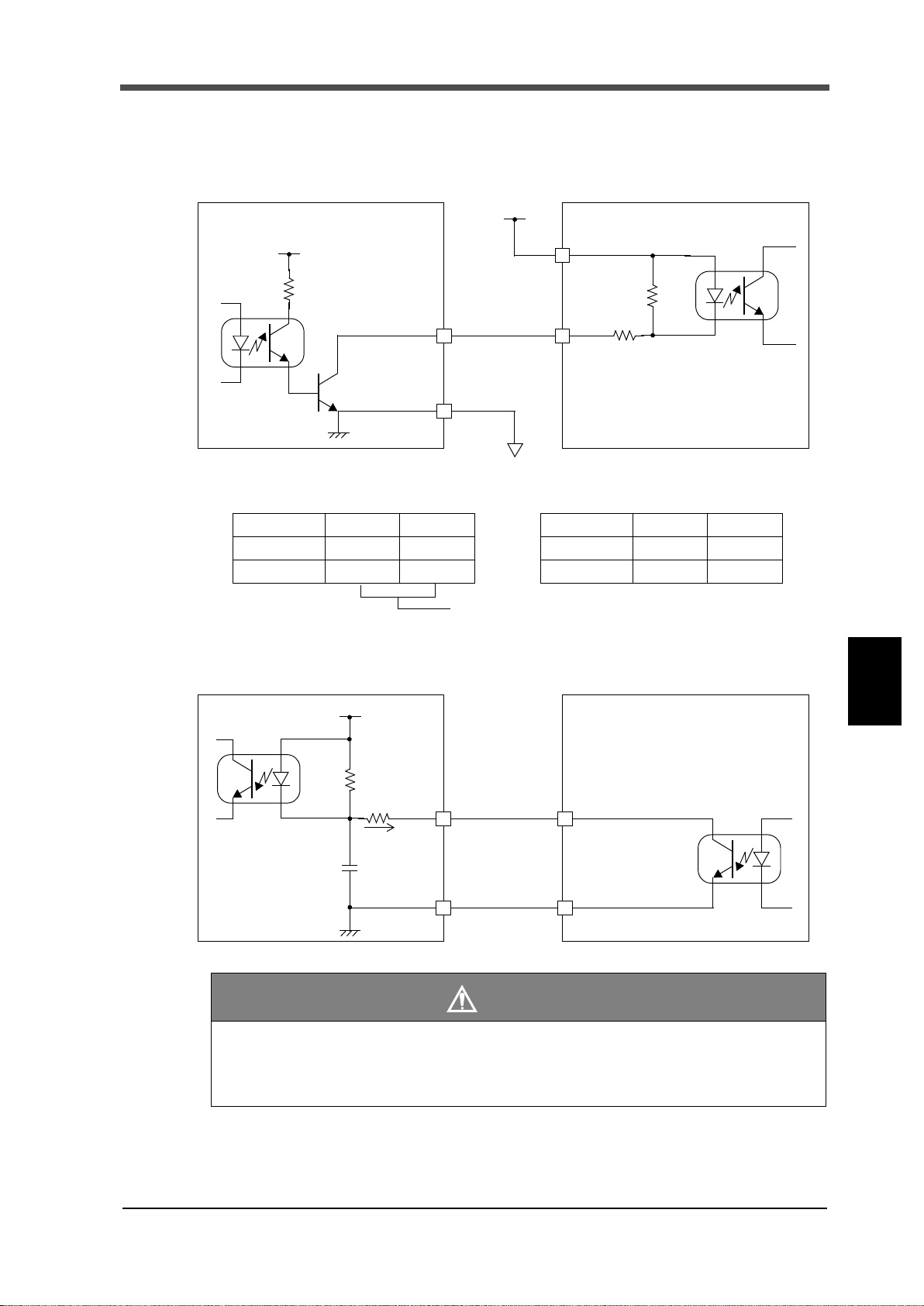
2-5. Connection of the external output (sink type)
The external output circuit is operated through an open collector. 6 is the common terminal.
The open collector output capacity is 120mA and the withstand voltage is up to 30V.
- Equivalent circuit
2-6. Connection of the external input
- Equivalent circuit (input)
Chapter
2
CONNECTION
9
- Avoid applying external voltages to the signal input circuit.
- Use external elements which withstands Ic=10mA or above.
- Leakage current from external element must be 30μA or below.
CAUTION
9

3 SETTING METHOD
3 SETTING METHOD
Download a compressed file from download page to a PC.
Decompress the compressed file by the PC then start installer.
Complete the installation according to the guide.
3-1. Preparation of PC
■PC hardware requirement
Chapter
3
SETTING METHOD
■Installation of a USB driver
OS: Windows7 Home Premium/Professional/Ultimate 32/64bit
English-language edition, The simplified chinese edition
Display: 800×600 pixels or more
USB port: One empty port
USB driver: Virtual COM Port(VCP) Drivers by FTDI Ltd.
Please install a USB driver for connecting with USB of the F331.
Please see the homepage of FTDI for details and perform download and installation of the driver
according to a procedure.
Guide: http://www.ftdichip.com/Support/Documents/InstallGuides.htm
Driver: http://www.ftdichip.com/Drivers/VCP.htm
■Connection of USB
Please the cap of the USB connector and connects a USB cable.
The USB connector of the F331 is mini-B TYPE.
■The check of a virtual COM port
Please check the virtual COM port number which the F331 is connected from the device manager
of PC.
3-2. Starting of the F331 PC application software
■Installation of the F331 PC application software
Setting up the F331 by the F331 PC application software and use it for data management at system
introduction and data analysis for troubleshooting.
Please download and install it from the Unipulse homepage.
* http://www.unipulse.com/en/products/index.html
10
10
■The injection of a power supply
EXE file
The indicating value of the F331
On the power supply of F331.
Please check that a display comes.
■Starting of the F331 PC application software
The F331 PC application software will start by executing an EXE file.
If there is no shortcut on the desktop, please run the EXE file from the
destination folder.
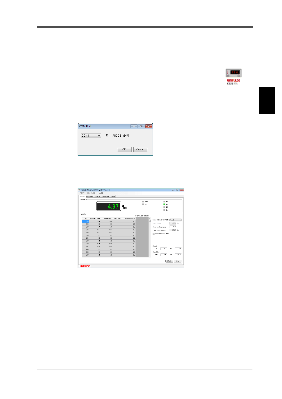
■Specification of a COM port
Please specify virtual COM port that is confirmed on "COM port" in the window menu.
3 SETTING METHOD
Chapter
3
■The check of a indicating value
Check if indicating value on the F331 is displayed.
* It is a Logging screen at the first time starting.
SETTING METHOD
11
11

3 SETTING METHOD
3-3. List of setting values
■Comparison setting
HH limit +9999 -9999 to +9999 P. 16
HI limit +0750 -9999 to +9999 P. 16
LO limit +0250 -9999 to +9999 P. 16
LL limit -9999 -9999 to +9999 P. 16
Chapter
3
SETTING METHOD
Hysteresis 0000 0000 to 9999 P. 17
Digital offset 0000 -9999 to +9999 P. 18
Near zero 0000 0000 to 9999 P. 18
Comparison timing 0: Always
■Operation setting
Moving average filter 1 1 to 512 [times] P. 18
Digital low-pass filter 2: 12 0: 3, 1: 6, 2: 12 [Hz] P. 18
Hold mode 0: OFF
ZERO key valid/invalid 0: Valid 0: Valid, 1: Invalid P. 21
Display frequency 2: 20 0: 5, 1: 10, 2: 20 [times/sec.] P. 21
External
output selection
Item Initial value Setting range Page
0: Always, 1: NZ,
2: Hold/Judge, 3: NZ+Hold/Judge
Item Initial value Setting range Page
0: OFF, 1: Sample, 2: Peak,
3: Valley, 4: P-P
Output selection 1 3: HI 0: OK, 1: NG, 2: HH, 3: HI, 4: LO, 5: LL
Output selection 2 4: LO 0: OK, 1: NG, 2: HH, 3: HI, 4: LO, 5: LL
P. 1 8
P. 1 9
P. 2 3
■Calibration setting
Item Initial value Setting range Page
Zero calibration 0.000 -3.000 to 3.000 [mV/V] P. 14
Equivalent input calibration (rated output) 3.000 0.500 to 3.000 [mV/V] P. 14
Actual load calibration (capacity) 1000 0001 to 9999 P. 14
Decimal place 2: 0.00 0: None, 1: 0.0, 2: 0.00, 3: 0.000 P. 15
Indicator ID All 20H
Loadcell ID All 20H
20H to 60H, 7BH to 7EH
20 bytes of ASCII code
20H to 60H, 7BH to 7EH
20 bytes of ASCII code
P. 1 5
P. 1 5
12
12
3 SETTING METHOD
■Option setting
Item Initial value Setting range Page
BCD output mode
BCD data update rate 0: 300
BCD external
output selection
D/A output mode
D/A zero scale 0000 -9999 to +9999 P. 30
D/A full scale 1000 -9999 to +9999 P. 30
RS-485 communication mode 0: Command
RS-485 I/F setting
RS-485 ID 01 00 to 31 P. 33
RS-485 transmission delay time 00 00 to 99 [ms] P. 39
RS-232C communication mode 0: Command
RS-232C I/F setting
Setting value LOCK (485/232) 0: OFF 0: OFF, 1: ON
Calibration value LOCK (485/232) 0: OFF 0: OFF, 1: ON
Output selection 1 2: HH 0: OK, 1: NG, 2: HH, 3: HI, 4: LO, 5: LL
Output selection 2 5: LL 0: OK, 1: NG, 2: HH, 3: HI, 4: LO, 5: LL
Baud rate 4: 19200
Length of character 1: 8bit 0: 7bit, 1: 8bit
Parity bit 2: even 0: None, 1: odd, 2: even
Stop bit 0: 1bit 0: 1bit, 1: 2bit
Delimiter 0: CR 0: CR, 1: CR+LF
Baud rate 4: 19200
Length of character 1: 8bit 0: 7bit, 1: 8bit
Parity bit 2: even 0: None, 1: odd, 2: even
Stop bit 0: 1bit 0: 1bit, 1: 2bit
Delimiter 0: CR 0: CR, 1: CR+LF
0: Linked with
indicated value
0: Linked with
indicated value
0: Linked with indicated value,
1: Not linked with indicated value
0: 300, 1: 100, 2: 50, 3: 30,
4: 10, 5: 5, 6: 3, 7: 1 [times/sec.]
0: Linked with indicated value,
1: Not linked with indicated value,
2: Zero scale, 3: Full scale
0: Command, 1: Continuous1,
2: Continuous2, 3: Modbus-RTU
0: 1200, 1: 2400, 2: 4800,
3: 9600, 4: 19200, 5: 38400 [bps]
0: Command, 1: Continuous1,
2: Continuous2,
0: 1200, 1: 2400, 2: 4800,
3: 9600, 4: 19200, 5: 38400 [bps]
P. 2 7
P. 2 7
P. 2 7
P. 3 0
P. 3 3
P. 3 3
P. 5 9
P. 5 9
P. 5 7
P. 6 5
Chapter
3
SETTING METHOD
13
3-4. Setting procedure
Setting by specific PC software.
For details, see the help of PC software.
13

4 HOW TO CALIBRATION
4 HOW TO CALIBRATION
A data sheet will be attached to a strain gauge sensor you buy.
On the data seat, the following values are listed.
Capacity .................... Load (unit: kg, t, etc.)
Rated Output............. Voltage (unit: mV/V)
Non-Linearity, Hysterisis, Input Resistance, Output Resistance,
Zero Balance, etc.
The Capacity and the Rated Output are necessary values for the equivalent input
calibration. Input these two values to F331.
Point
"Calibration" refers to an operation whereby matching between the F331 and a strain gauge sensor
is obtained. The F331 uses the calibration methods as described below.
◇Zero calibration
Register the initial zero point.
Check around the strain gauge sensor for unwanted loads such as foreign object is placed or there is
contact with peripheral equipment.
Chapter
4
HOW TO CALIBRATION
◇Equivalent input calibration
This approach uses no actual loads but setting of the rated output value of the strain gauge sensor
(mV/V) and the rating value (value to be displayed).
This method is simple and employed when actual loads cannot be applied.
For example
Gain will be automatically decided by registering the values indicated as follows:
For load: 2.001mV/V - 100.0kgf
For pressure: 2.002mV/V - 10.00kgf/cm2, and
For torque: 2.502mV/V - 15.00kgf.m.
◇Actual load calibration
This approach provides calibration by applying an actual load to the strain gauge sensor and setting
the actual load value. This calibration is without little errors and more correct.
14
14

4 HOW TO CALIBRATION
Equivalent input calibration
Setting decimal place
Zero calibration
Actual load calibration
Setting decimal place
Zero calibration
4-1. Equivalent input calibration procedure
The equivalent input calibration uses the following procedure;
Set the decimal place. (omissible if no desired value is present)
Set the zero point of the strain gauge sensor.
Set the rated output vale and rating value of the strain gauge sensor.
4-2. Actual load calibration procedure
The actual load calibration uses the following procedure;
Chapter
4
4-3. Decimal place
This function sets the Position of decimal point.
4-4. Equipment ID
F331 can be set Equipment ID for identification.
Equipment ID has Indicator ID and Loadcell ID.
Setting be 20 bytes (20H to 60H, 7BH to 7EH) of ASCII code.
Set the decimal place. (Omissible if no desired value is present)
Set the zero point of the strain gauge sensor.
Set the span(gain) point of the strain gage sensor.
HOW TO CALIBRATION
15
15

5 SETTING OF FUNCTIONS
5 SETTING OF FUNCTIONS
- Comparison conditions is a case where a setup of comparison timing is "always".
- Suiting ON condition immediately displays the messages.
Point
Time
Indicated value
HI limit
LO limit
HI
LO
OFF
ON
OFF
ON
5-1. HI-LO limit comparison
< Comparison conditions >
- HH
ON condition: Indicated value > HH limit value ( ⇔Indicated value displayed alternately)
OFF condition: Indicated value ≦ HH limit value
- HI
ON condition: Indicated value > HI limit value ( ⇔Indicated value displayed alternately)
OFF condition: Indicated value ≦ HI limit value
- LO
Chapter
5
SETTING OF FUNCTIONS
ON condition: Indicated value < LO limit value ( ⇔Indicated value displayed alternately)
OFF condition: Indicated value ≧ LO limit value
- LL
ON condition: Indicated value < LL limit value ( ⇔Indicated value displayed alternately)
OFF condition: Indicated value ≧ LL limit value
- OK
ON condition: HH, HI, LO and LL are OFF. (OK lights up)
OFF condition: When either of HH, HI, LO or LL is ON.
- NG
ON condition: When OK is OFF. (OK lights turned off)
OFF condition: When OK is ON.
< The example of HI/LO limit output of operation >
16
16

5-2. Hysteresis
Hysteresis setting is the same for HH/HI/LO/LL limit.
Point
HI limit
LO limit
+
0
Hysteresis range
Time
-
Indicated value
OFF
ON
With hysteresis
Without hysteresis
By setting hysteresis, cha
ttering can be prevented
in such a case as subtle
fluctuations of signals.
HI limit
HI
LO
OFF
ON
OFF
ON
OFF
ON
The hysteresis value may be determined so as to allow a margin for timing the turning off of the HI/
LO limit comparison. Normally, it is turned on when the indicated value exceeds the HI limit and is
turned off when the indicated value falls below it. However, by setting the hysteresis, it is turned off
when the indicated value falls below the HI limit further lowered by the hysteresis value. This
function is effective to prevent chattering in such a case where signals fluctuate (vibrate) subtly.
< Comparison conditions >
- HH
ON condition: Indicated value > HH limit value
OFF condition: Indicated value ≦ (HH limit value - hysteresis value)
- HI
ON condition: Indicated value > HI limit value
OFF condition: Indicated value ≦ (HI limit value - hysteresis value)
- LO
ON condition: Indicated value < LO limit value
OFF condition: Indicated value ≧ (LO limit value + hysteresis value)
- LL
ON condition: Indicated value < LL limit value
OFF condition: Indicated value ≧ (LL limit value + hysteresis value)
5 SETTING OF FUNCTIONS
Chapter
5
< The example of hysteresis operation >
SETTING OF FUNCTIONS
17
17

5 SETTING OF FUNCTIONS
Near zero ON/OFF is closely related to the Comparison timing.
See "5-4.Comparison timing" on page 18.
Point
5-3. Near zero
By this function, it is detected that the indicated value is near zero.
ON condition: | indicated value | ≦ near zero setting value (0 is excluded.)
OFF condition: | indicated value | > near zero setting value
5-4. Comparison timing
Set the operating condition of HI-LO limit comparison.
Always: Comparison is always performed.
Chapter
NZ: Comparison is performed when near zero is OFF.
5
Hold/Judge: Comparison is performed when indicated value is held
SETTING OF FUNCTIONS
NZ:+Hold/Judge Comparison is performed when near zero is off and indicated value is held
5-5. Digital offset
This function subtracts a set value from the indicated value. If you make digital offset , the value
which is obtained by subtracting the set value from the indicated value will be displayed. This is
convenient when you cannot obtain zero by unloading the equipment for some reason or when you
want to give offset.
(Indicated value to be displayed) = (Actual indicated value) - (Digital offset setting value)
5-6. Moving average filter
This function restrains the indicated value from fluctuating by moving-averaging the A/Dconverted
data. The moving average times can be selected in the range of OFF (1 time) - 512 times. With an
increasing number of moving average times, the indicated value becomes more stable, while the
response becomes slower. On the other hand, with a decreasing number of moving average times,
the response becomes faster, while the indicated value becomes easier to fluctuate.
(external judging input is ON when hold mode is OFF).
(external judging input is ON when hold mode is OFF).
5-7. Digital low pass filter
This low pass filter cancels undesired noise components by filtering the A/D-converted data. Set
the cutoff frequency like a low pass filter in an analog circuit. The cutoff frequency can be selected
from 3, 6, 12Hz. Select an optimum value according to the type of measurement and setting
environment.
18
18

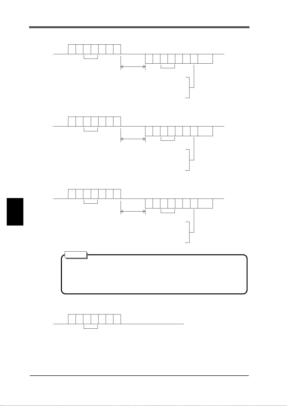
5-8. Hold mode
Time
Indicated value
Sensor input value
HOLD
input
OFF
ON
t1 to t3: MAX 20mS
t2
t3
t1
Hold
ON OFFOFF
HOLD
LED
Time
Indicated value
Sensor input value
HOLD
t2
t3
t4
t1
input
OFF
ON
t1 to t3: MAX 20mS
Detection
ON OFFOFF
HOLD
LED
blinkingON
blinking
t4: Approx. 0.5s
Hold
Hold
t4
Detection
■Sample (The arbitrary points are held.)
< Timing chart >
5 SETTING OF FUNCTIONS
Chapter
t1: Time from when the hold signal is inputted to when the indicated value is held
t2: Time from when the hold signal is cancelled to when the indicated value returns to tracking
t3: Minimum reset signal width required for canceling the hold
■Peak (The maximum point is held.)
< Timing chart >
5
SETTING OF FUNCTIONS
19
t1: Time from when the hold signal is inputted to when the indicated value is held
t2: Time from when the hold signal is cancelled to when the indicated value returns to tracking
t3: Minimum reset signal width required for canceling the hold
t4: Time after updating a hold value until it holds
* HOLD LED is blinked after HOLD start for the 1st time.
19

Chapter
Time
Indicated value
Sensor input value
HOLD
t2
t3
t4
t1
input
OFF
ON
t1 to t3: MAX 20mS
HOLD
LED
t4: Approx. 0.5s
t4
Detection
ON OFFOFF blinkingON
blinking
Hold
HoldDetection
Time
Indicated value
Sensor input value
HOLD
input
OFF
ON
t1 to t3: MAX 20mS
t3
Hold
blinking OFFOFF
HOLD
LED
Standard line
t2
t1
t4
t4: Approx. 0.5s
ON
blinking
DetectionDetection
Indicated value=0
5 SETTING OF FUNCTIONS
■Bottom (The minimum point is held.)
< Timing chart >
5
t1: Time from when the hold signal is inputted to when the indicated value is held
SETTING OF FUNCTIONS
■P-P (The difference of the maximum point and the minimum point is held.)
t2: Time from when the hold signal is cancelled to when the indicated value returns to tracking
t3: Minimum reset signal width required for canceling the hold
t4: Time after updating a hold value until it holds
* HOLD LED is blinked after HOLD start for the 1st time.
< Timing chart >
20
20
t1: Time from when the hold signal is inputted to when the indicated value is held
t2: Time from when the hold signal is cancelled to when the indicated value returns to tracking
t3: Minimum reset signal width required for canceling the hold
t4: Time after updating a hold value until it holds
* HOLD LED is blinked after HOLD start for the 1st time.

5-9. Digital zero function
ZERO
Digital zero
OFF
ON
Turn ON for 50 msec or more.
- The digital zero function is reset when the power is turned OFF.
- For the connection of the digital zero input terminals, see "2-6.Connection of
the external input" on page 9.
- If the digital offset is set, even if Digital Zero is executed, zero will not result.
(Indicated value = -Setting value of digital offset)
Point
This function zeros the indicated value.
■Digital zero by key operation
Press the .
1.
2. When the indicated value becomes zero, digital zero is completed.
Display Message description
Invalid ZERO key operations.
■Digital zero by external signal input
At the instant when the digital zero input (8) and COM (6) on the signal input/output terminal block
at the back are short-circuited, the digital zero function works to zero the indicated value.
5 SETTING OF FUNCTIONS
Chapter
5-10.ZERO key valid/invalid
This function validates/invalidates the operation of the ZERO key.
5-11.Display frequency
5
SETTING OF FUNCTIONS
The Display frequency function is used to select the times the indicated values are displayed per
second. A/D conversion count is fixed to 300 per second.
21
21

6 EXTERNAL INPUT/OUTPUT SIGNALS
6
EXTERNAL INPUT/OUTPUT SIGNALS
Signal input/output
678910
IN1 IN2 OUT1 OUT2
78910
COM
6
terminal block
OFF
Hold ON
ON
OFF
Hold OFF
ON
OFF
Judge ON
ON
OFF
Judge OFF
ON
OFF
ON
Pulse width 50mSec or more
6-1. Connector pin assignments
6-2. External input signals
IN1: Hold/Judge
IN2: Digital zero
Chapter
6
EXTERNAL INPUT/OUTPUT SIGNALS
■Hold/Judge <edge input>
For hold signal, please use hold mode.
When the hold mode is OFF, it operates as a judgment signal of comparison timing.
However, it is unrelated when comparison timing condition is ALWAYS or NZ.
■Digital zero <edge input>
The digital zero works to zero the indicated value.
22
22

6-3. External output signals
External output selection
Output selection 1*
Output selection 2*
* 0: OK 1: NG 2: HH 3: HI 4: LO 5: LL
■External output selection
Each signal of comparison outputs is selectable by setting.
OUT1: Output selection 1
OUT2: Output selection 2
Select from OK, NG, HH, HI, LO, and LL.
■OK/ NG/ HH/ HI/ LO/ LL
6 EXTERNAL INPUT/OUTPUT SIGNALS
Each signal turns ON when the comparison condition is met.
* See "5-1.HI-LO limit comparison" on page 16 to "5-4.Comparison timing" on page 18.
Chapter
6
EXTERNAL INPUT/OUTPUT SIGNALS
23
23

7 OPTION
7 OPTION
A16
B16
A1
B1
Case (two)
Screw (two)
Connector
M2×10 pan-head machinescrew
M2 nut (four)
Washer (two)
(short) (two) (long) (two)
M2×8 pan-head machine screw
7-1. BCD data output
The BCD data output interface is used to obtain the indicated value of the F331 as BCD data. It is
convenient for connecting the F331 with a computer, process controller, PLC, etc., to perform
processing, such as controlling, aggregating, and recording.
Assembling connector
Chapter
7
OPTION
1. Align the connector and each screw (two) in the groove in one case.
2. Put the other case on it, and fit the cases together.
3. Tighten each M2×8 pan-head machine screw (two).
Tighten each M2×10 pan-head machine screw (two).
Be aware that the M2×10 pan-head machine screw should be combined
with a washer.
24
24
■Equivalent circuit
● Internal transistor status
Output data Negative Positive
0OFFON
1ONOFF
● Output pin level
Output data Negative Positive
0HL
1LH
Through logic switching( pin B14)
Output
COM
+24VRTN
COM
Input
+24V
F331
Sink type
PLC input unit etc.
Plus common type
A2 to A13
B2 to B13
A1, B1
+12V
Vceo=30V(max)
Ic=50mA(max)
F331 PLC output unit etc.
Sink type
Output
COM
Ic=
Input
COM
A1, B1
A14, B14
+12V
Approx.6mA
Output
7 OPTION
Input
- Avoid applying external voltages to the signal input circuit.
- Use external elements which withstands Ic=10mA or above.
- Leakage current from external element must be 30μA or below.
Chapter
7
OPTION
CAUTION
25
25

7 OPTION
Strobe Range
0
1
BCD data
OVER
STROBE
(duty 50%)
■Connector pin assignment
No. Signal No. Signal
A1 *COMB1 *COM
A2 Out 1 B2 Out 1000
A3 Out 2 B3 Out 2000
A4 Out 4 B4 Out 4000
A5 Out 8 B5 Out 8000
A6 Out 10 B6 Out
A7 Out 20 B7 Out Output selection 1
A8 Out 40 B8 Out Output selection 2
A9 Out 80 B9 Out NZ
A10 Out 100 B10 Out Minus (polarity)
A11 Out 200 B11 Out OVER
A12 Out 400 B12 Out
A13 Out 800 B13 Out STROBE
A14 In BCD data hold B14 In Logic switching
A15 N.C. B15 N.C.
A16 N.C. B16 N.C.
Chapter
7
OPTION
Compatible connector: FCN-361J032-AU (manufactured by Fujitsu Component or an equivalent)
Connector cover: FCN-360C032-B (manufactured by Fujitsu Component or an equivalent)
Output selection 1, Output selection 2 (Linked with indicated value)
Output signal can be assigned.
Select from OK, NG, HH, HI, LO, and LL.
NZ (Linked with indicated value)
The state of near zero is outputted.
Minus (polarity)
The polarity of the indicated value as BCD data is outputted.
OVER
It is outputted at the time of over scale(-LOAD, +LOAD, OFL1 or OFL2).
STROBE
Strobe pulses are outputted in synchronization with BCD data. Read data using the rising edges (1
→0) of the pulses. The setting of BCD data update rate can be changed.
26
26

BCD data hold -Level input-
When level input is OFF, output signal is hold release.
Hold release Hold
Undefined section (20ms or less)
OFF
ON
When level input is ON, output signal is hold.
When level input is OFF, output signal is negative logic.
Negative logic Positive logic
Undefined section (20ms or less)
OFF
ON
When level input is ON, output signal is positive logic.
BCD external output selection
Output selection 1*
Output selection 2*
* 0: OK 1: NG 2: HH 3: HI 4: LO 5: LL
Renewal of the BCD data output signal is stopped. (The indicated value is not held.)
Also the STROBE output is turned OFF.
It is carried out by pin A14.
Logic switching -Level input-
Switch the output signal logic with pin B14.
7 OPTION
■BCD output mode
Set the BCD output mode of F331.
Linked with indicated value
Output linked with indicated value.
When the indicated value is held, the held value is outputted even if the sensor input signal changes.
Not linked with indicated value
Scaled output linked with sensor input.
Even if the indicated value is held, an output is made according to the changes in sensor input
signal.
■BCD data update rate selection
Normaly, BCD data update synchronous the A/D conversion (300 times/sec.).
When the BCD input equipment is low ability and can not read out the high rate of 300 times/sec.,
set the BCD data update rate is low.
■BCD external output selection
Output signal can be assigned.
Select from OK, NG, HH, HI, LO, and LL.
Chapter
7
OPTION
27
27

7 OPTION
Current output terminals
Terminals for obtaining current signal.
4 to 20mA can be obtained.
Gain adjustment trimmer
For fine adjustment of gain. Trimmer
adjusts output to 20mA for full scale.
Adjustment can also be made by using
the fixed output mode.
Zero adjustment trimmer
For fine adjustment of zero. Trimmer
adjusts output to 4mA for zero scale.
Adjustment can also be made by using
the fixed output mode.
CUR. GND
7-2. D/A converter
■Current output (DAI option)
This converter is used to obtain an analog output which is linked with the indicated value of the
F331.
The range of the analog output is from 4 to 20mA.
An analog output from 4mA to 20mA can be obtained with respect to any digital values set by the
D/A zero scale setting and the D/A full scale setting functions.
The output circuit and the main circuit are isolated.
Chapter
7
OPTION
Current output: 4 to 20mA (load resistance; 500Ω or less)
D/A conversion speed: 300times/sec.
Resolution: 1/10000
Over range: 2.4 to 21.6mA
Zero drift: Within 0.5μA/ ℃
Gain drift: Within 50ppm/ ℃
Non-linearity: Within 0.05%FS
* Not including the drift of the analog input section
Connector: M3 screw type terminal block (two-pole)
* Compatible solderless terminal within 5.9mm
Tightening torque 0.6N•m
28
28

Obtaining current output signal
+
-
External device
Load resistance;
500Ω or less
FG
← Inside Outside →
CUR.
GND
F331
Current (mA)
20
4
D/A zero scale
Indicated
D/A full scale
Resolution 1/10000
value
Current (mA)
20
4
D/A zero scale
Indicated value
D/A full scale
Resolution 1/10000
500 2500
Indicated value Current (mA)
480 3.84
500 4.00
1000 8.00
1500 12.00
2500 20.00
2520 20.16
Zero scale
Full scale
Use the CUR. and GND terminals of the
F331 for connection with an external
device (500Ω or less load resistance).
CAUTION
- The D/A converter current output is an option.
- Do not apply external currents. Breakage will result.
Also, connecting a capacity load may cause oscillation.
Setting of D/A zero and gain
7 OPTION
With the D/A converter of the F331, an analog
output is obtained by setting the indicated value
to output 4mA (D/A zero scale) and the
indicated value to output 20mA (D/A full
scale). Respective set values are inputted by the
D/A zero and full scale setting functions.
Example of setting
In the case where:
D/A output mode...................... 0 (linked with indicated value)
D/A zero scale.......................... 0500
D/A full scale ........................... 2500
Chapter
7
OPTION
29
29

7 OPTION
About D/A resolution
The resolution of the D/A converter is 1/10000 with respect to 4 to 20mA.
In other words, the minimum unit of voltage is:
(20 - 4mA) × 1/10000 = 1.6μA.
Also, the minimum unit of indicated value is:
(D/A full scale - D/A zero scale) × 1/10000.
■D/A zero and full scale
Set the D/A zero and full scale of the F331.
* Please be sure to set up zero scale < full scale.
■D/A output mode
Set the D/A output mode of the F331.
Linked with indicated value
Chapter
7
OPTION
Analog output linked with indicated value.
When the indicated value is held, the held value is outputted even if the sensor input signal changes.
Not linked with indicated value
Scaled analog output linked with sensor input.
Even if the indicated value is held, an output is made according to the changes in sensor input
signal.
Zero scale fixed output
A fixed output of 4mA is made.
Full scale fixed output
A fixed output of 20mA is made.
30
30

7-3. RS-485 interface
B+
Rt.
A-
S.G.
The RS-485 interface is used to read out the indicated value and the state of the F331 and to write
set values into the F331. It is convenient for connecting the F331 with a PLC/programmable
display, etc., to perform processing, such as controlling, aggregating, and recording.
Connector: M3 screw type terminal block (four-pole)
* Compatible solderless terminal within 5.9mm
Tightening torque 0.6N•m
7 OPTION
■Communication specifications
Standards
Message format: Modbus-RTU, UNI-Format
Signal level: RS-485-compliant, two-wire
Transmission distance: Approx. 1km
Transmission mode: Asynchronous, half-duplex communication
Transmission speed: 1200, 2400, 4800, 9600, 19200, 38400bps selectable
Number of connectable units: Max. 32 (including one master)
Bit configuration: Start bit 1 bit
Length of character 7 or 8 bits selectable (8 bits for Modbus-RTU)
Stop bit 1 or 2 bits selectable
Parity bit None, odd, or even selectable
Code: Binary (for Modbus-RTU)
ASCII (for UNI-Format)
Chapter
7
OPTION
31
31

7 OPTION
A
-
B+
A
B
A
B
A
-
B+
F331
PLC/programmable
display, etc.
Terminating
(Master) (Slave)
* Logic
- Mark state (OFF)
V
A-VB
<-0.2V
- Space state (ON)
VA-VB>0.2V
VA: Voltage of terminal A
-
VB: Voltage of terminal B+
Terminating
resistance
* The F331 side terminating resistance (110Ω)
can be short bar-installable/uninstallable.
resistance
( * )
Rt. B+
Terminating resistance
Short bar
(110Ω) self-contained
A-
On some master devices, A and B may be indicated reversely.
If communications are unsuccessful, interchange A and B.
Attention
A
B
A- B+ A- B+ A- B+ A- B+
Twisted pair cables
F331 F331 F331 F331
Terminating
Terminating
resistance (110Ω)
can be
short bar-installable/
resistance
uninstallable.
■RS-485 connection
Two-wire type (point to point)
- For connection, use twisted pair cables. (The noise margin will rise.)
However, a parallel two-core cable is good enough for short-distance connection.
- Install terminating resistance each on the
host side and F331 side.
On the F331 side, connect Rt. and B+ with
a short bar.
Chapter
7
OPTION
- The terminal SG is a grand terminal used
on the circuit for protecting the circuit.
When the main body of F331 and the
device connected to F331 are grounded by
D type ground, there is usually no need to
use the terminal SG.
However, confirm the specifications of the devise connected before connecting the terminal SG,
when it is necessary to connect it according to the situation of the site.
Two-wire type (multi point)
32
32

■RS-485-related setting values
RS-485 I/F setting
The length of character
0: 7bit
1: 8bit
Baud rate
0: 1200bps
1: 2400bps
2: 4800bps
3: 9600bps
4: 19200bps
5: 38400bps
Delimiter
Stop bit
0: 1bit
1: 2bit
0: CR
1: CR+LF
Parity bit
0: None
1: Odd
2: Even
(effective at only UNI-Format)
(Initial value: 41200)
RS-485 ID (slave address)
ID setting (0 - 31)
(Initial value: 01)
RS-485 communication mode
Mode
0: Command
1: Continuous1
2: Continuous2
3: Modbus-RTU
(Initial value: 0)
See the RS-485-related settings by specific PC software.
Attention
■RS-485 I/F setting
1. Set the RS-485 port of this device.
* If the communication mode is Modbus-RTU, set as length of character: 8 bits and stop
bit: 1 bit (stop bit: 2 bits if the parity bit is none).
7 OPTION
2. Make initial settings of the RS-485 port of the personal computer, PLC, etc.,
connected according to the settings of this device.
■RS-485 ID (slave address for Modbus-RTU)
Input the ID setting.
■RS-485 communication mode
Set the RS-485 operation.
Chapter
7
OPTION
33
■Communication mode
- Communication mode 0 (mode=0: Command)
Communication is performed with the command from the host computer.
(Indicated value is not transmitted automatically.)
Delimiter is selectable from CR or CR + LF.
33

7 OPTION
(24byte)Transmission format 1
(26byte)Transmission format 2
For transmission formats, see "■Continuous transmission formats" on page 39.
Attention
About the timing for continuous transmission
According to the communication baud rate setting, the continuous
transmission intervals in the case where any of the communication modes
from 1 and 2 is selected are as follows:
Communication baud rate Continuous transmission interval
38400 bps 100
times/sec.
19200 bps 50 times/sec.
9600 bps 25 times/sec.
4800 bps 12 times/sec.
2400 bps 6 times/sec.
1200 bps 3 times/sec.
Point
Host
F331
N
RA
+
010 00.Delimiter
O RCRA
IDNo.
ID
IDNo.
0 fixed
- Communication mode 1 (mode=1: Continuous1)
Linked with indicated value is transmitted continuously.
Various commands of R, W, and C are all ignored.
- Communication mode 2 (mode=2: Continuous2)
Linked with indicated value and Not linked with indicated value are transmitted continuously.
Various commands of R, W, and C are all ignored
- Communication mode 3 (mode=3: Modbus-RTU)
Communication is performed by a request from the host computer.
(Communication protocol Modbus-RTU)
Various commands of R, W, and C are all ignored.
Chapter
7
OPTION
■UNI-Format commands
■Command communication formats
- Read the linked with indicated value (sign, 5-digit, decimal point)
34
34

- Read the not linked with indicated value (sign, 5-digit, decimal point)
Host
F331
N
RB
+
010 00
.
O RCRB
IDNo.
ID
IDNo.
0 fixed
Delimiter
Host
F331
N
RC 000 00
0
O RCRC
IDNo.
ID
IDNo.
0
+LOAD
-LOAD
OFL2
OFL1
HH
LL
Calibration error No.
0: OFF 1: ON
0: OFF 1: ON
0: OFF 1: ON
0: OFF 1: ON
0: OFF 1: ON
0: OFF 1: ON
F331 error No.
Delimiter
Host
F331
N
RD 000 00
0
O RCRD
IDNo.
ID
IDNo.
0
Under a hold/ Under a judgment
Undefined
NZ
HI
OK
LO
LOCK
0: OFF 1: ON
0
0: OFF 1: ON
0: OFF 1: ON
0: OFF 1: ON
0: OFF 1: ON
0: Setting value LOCK and calibration value LOCK OFF
1: Only setting value LOCK is turned ON
2: Only calibration value LOCK is turned ON
3: Setting value LOCK and calibration value LOCK ON
Delimiter
Host
F331
W CRNO
IDNo.
Setting value No.
Setting value
* No data returned
(sign, 5-digit, no decimal point)
Host
F331
W
W
CRNO
IDNo.
ID
IDNo.
Setting value No.
Delimiter
Setting value
Setting value No. (sign, 5-digit, no decimal point)
- Status 1
7 OPTION
- Status 2
- Write the setting value
* For setting value No., see "■Setting value communication formats" on page 37.
Chapter
7
OPTION
- Read the setting value
35
* For setting value No., see "■Setting value communication formats" on page 37.
35
7 OPTION
Host
F331
CA
N0A
Calibration in progress
CRNO
IDNo.
ID
IDNo.
0: Normal end
2 - 9: F331 error No.
L: Calibration disabled by calibration LOCK
R: Calibration in progress
Delimiter
Host
F331
CB
N0B
Calibration in progress
CRNO
IDNo.
ID
IDNo.
0: Normal end
2 - 9: F331 error No.
L: Calibration disabled by calibration LOCK
R: Calibration in progress
Delimiter
Host
F331
CV
N0V
Calibration in progress
CRNO
IDNo.
ID
IDNo.
0: Normal end
2 - 9: F331 error No.
L: Calibration disabled by calibration LOCK
R: Calibration in progress
Delimiter
Please set up capacity value before sending the command of actual load
calibration.
Please set up rated output value and capacity value before sending the
command of equivalent input calibration.
Attention
Host
F331
CE
* No data returned
CR
NO
IDNo.
- Zero calibration
- Actual load calibration
Chapter
7
OPTION
- Equivalent input calibration
- Hold/Judge ON
36
36

- Hold/Judge OFF
Host
F331
CF
* No data returned
CRNO
IDNo.
Host
F331
CG
* No data returned
CR
NO
IDNo.
Host
F331
CH
* No data returned
CR
NO
IDNo.
㪟㪟㩷㫃㫀㫄㫀㫋
㪥 㪦 㪮 㪇 㪈 㫧 㪇 㩿㫎㫉㫀㫋㪼㪄㫀㫅㪿㫀㪹㫀㫋㪼㪻㩷㫎㪿㪼㫅㩷㪪㪼㫋㫋㫀㫅㪾㩷㫍㪸㫃㫌㪼㩷㪣㪦㪚㪢㩷㫀㫊㩷㪸㫇㫇㫃㫀㪼㪻㪀
㪟㪠㩷㫃㫀㫄㫀㫋
㪥 㪦 㪮 㪇 㪉 㫧 㪇 㩿㫎㫉㫀㫋㪼㪄㫀㫅㪿㫀㪹㫀㫋㪼㪻㩷㫎㪿㪼㫅㩷㪪㪼㫋㫋㫀㫅㪾㩷㫍㪸㫃㫌㪼㩷㪣㪦㪚㪢㩷㫀㫊㩷㪸㫇㫇㫃㫀㪼㪻㪀
㪣㪦㩷㫃㫀㫄㫀㫋
㪥 㪦 㪮 㪇 㪊 㫧 㪇 㩿㫎㫉㫀㫋㪼㪄㫀㫅㪿㫀㪹㫀㫋㪼㪻㩷㫎㪿㪼㫅㩷㪪㪼㫋㫋㫀㫅㪾㩷㫍㪸㫃㫌㪼㩷㪣㪦㪚㪢㩷㫀㫊㩷㪸㫇㫇㫃㫀㪼㪻㪀
㪣㪣㩷㫃㫀㫄㫀㫋
㪥 㪦 㪮 㪇 㪋 㫧 㪇 㩿㫎㫉㫀㫋㪼㪄㫀㫅㪿㫀㪹㫀㫋㪼㪻㩷㫎㪿㪼㫅㩷㪪㪼㫋㫋㫀㫅㪾㩷㫍㪸㫃㫌㪼㩷㪣㪦㪚㪢㩷㫀㫊㩷㪸㫇㫇㫃㫀㪼㪻㪀
㪟㫐㫊㫋㪼㫉㪼㫊㫀㫊
㪥㪦 㪮㪇㪌㪇㪇 㩿㫎㫉㫀㫋㪼㪄㫀㫅㪿㫀㪹㫀㫋㪼㪻㩷㫎㪿㪼㫅㩷㪪㪼㫋㫋㫀㫅㪾㩷㫍㪸㫃㫌㪼㩷㪣㪦㪚㪢㩷㫀㫊㩷㪸㫇㫇㫃㫀㪼㪻㪀
㪛㫀㪾㫀㫋㪸㫃㩷㫆㪽㪽㫊㪼㫋
㪥 㪦 㪮 㪇 㪍 㫧 㪇 㩿㫎㫉㫀㫋㪼㪄㫀㫅㪿㫀㪹㫀㫋㪼㪻㩷㫎㪿㪼㫅㩷㪪㪼㫋㫋㫀㫅㪾㩷㫍㪸㫃㫌㪼㩷㪣㪦㪚㪢㩷㫀㫊㩷㪸㫇㫇㫃㫀㪼㪻㪀
㪥㪼㪸㫉㩷㫑㪼㫉㫆
㪥㪦 㪮㪇㪎㪇㪇 㩿㫎㫉㫀㫋㪼㪄㫀㫅㪿㫀㪹㫀㫋㪼㪻㩷㫎㪿㪼㫅㩷㪪㪼㫋㫋㫀㫅㪾㩷㫍㪸㫃㫌㪼㩷㪣㪦㪚㪢㩷㫀㫊㩷㪸㫇㫇㫃㫀㪼㪻㪀
㪚㫆㫄㫇㪸㫉㫀㫊㫆㫅㩷㫋㫀㫄㫀㫅㪾
㪥㪦 㪮㪇㪏㪇㪇㪇㪇㪇 㩿㫎㫉㫀㫋㪼㪄㫀㫅㪿㫀㪹㫀㫋㪼㪻㩷㫎㪿㪼㫅㩷㪪㪼㫋㫋㫀㫅㪾㩷㫍㪸㫃㫌㪼㩷㪣㪦㪚㪢㩷㫀㫊㩷㪸㫇㫇㫃㫀㪼㪻㪀
㪤㫆㫍㫀㫅㪾㩷㪸㫍㪼㫉㪸㪾㪼㩷㪽㫀㫃㫋㪼㫉
㪥㪦 㪮㪈㪈㪇㪇㪇 㩿㫎㫉㫀㫋㪼㪄㫀㫅㪿㫀㪹㫀㫋㪼㪻㩷㫎㪿㪼㫅㩷㪪㪼㫋㫋㫀㫅㪾㩷㫍㪸㫃㫌㪼㩷㪣㪦㪚㪢㩷㫀㫊㩷㪸㫇㫇㫃㫀㪼㪻㪀
㪛㫀㪾㫀㫋㪸㫃㩷㫃㫆㫎㪄㫇㪸㫊㫊㩷㪽㫀㫃㫋㪼㫉
㪥㪦 㪮㪈㪉㪇㪇㪇㪇㪇 㩿㫎㫉㫀㫋㪼㪄㫀㫅㪿㫀㪹㫀㫋㪼㪻㩷㫎㪿㪼㫅㩷㪪㪼㫋㫋㫀㫅㪾㩷㫍㪸㫃㫌㪼㩷㪣㪦㪚㪢㩷㫀㫊㩷㪸㫇㫇㫃㫀㪼㪻㪀
㪛㪼㪺㫀㫄㪸㫃㩷㫇㫃㪸㪺㪼
㪥㪦 㪮㪈㪊㪇㪇㪇㪇㪇 㩿㫎㫉㫀㫋㪼㪄㫀㫅㪿㫀㪹㫀㫋㪼㪻㩷㫎㪿㪼㫅㩷㪚㪸㫃㫀㪹㫉㪸㫋㫀㫆㫅㩷㫍㪸㫃㫌㪼㩷㪣㪦㪚㪢㩷㫀㫊㩷㪸㫇㫇㫃㫀㪼㪻㪀
㪱㪜㪩㪦㩷㫂㪼㫐㩷㫍㪸㫃㫀㪻㪆㫀㫅㫍㪸㫃㫀㪻
㪥㪦 㪮㪈㪋㪇㪇㪇㪇㪇 㩿㫎㫉㫀㫋㪼㪄㫀㫅㪿㫀㪹㫀㫋㪼㪻㩷㫎㪿㪼㫅㩷㪪㪼㫋㫋㫀㫅㪾㩷㫍㪸㫃㫌㪼㩷㪣㪦㪚㪢㩷㫀㫊㩷㪸㫇㫇㫃㫀㪼㪻㪀
㪟㫆㫃㪻㩷㫄㫆㪻㪼
㪥㪦 㪮㪈㪌㪇㪇㪇㪇㪇 㩿㫎㫉㫀㫋㪼㪄㫀㫅㪿㫀㪹㫀㫋㪼㪻㩷㫎㪿㪼㫅㩷㪪㪼㫋㫋㫀㫅㪾㩷㫍㪸㫃㫌㪼㩷㪣㪦㪚㪢㩷㫀㫊㩷㪸㫇㫇㫃㫀㪼㪻㪀
㪛㫀㫊㫇㫃㪸㫐㩷㪽㫉㪼㫈㫌㪼㫅㪺㫐
㪥㪦 㪮㪈㪍㪇㪇㪇㪇㪇 㩿㫎㫉㫀㫋㪼㪄㫀㫅㪿㫀㪹㫀㫋㪼㪻㩷㫎㪿㪼㫅㩷㪪㪼㫋㫋㫀㫅㪾㩷㫍㪸㫃㫌㪼㩷㪣㪦㪚㪢㩷㫀㫊㩷㪸㫇㫇㫃㫀㪼㪻㪀
㪜㫏㫋㪼㫉㫅㪸㫃㩷㫆㫌㫋㫇㫌㫋㩷㫊㪼㫃㪼㪺㫋㫀㫆㫅
㪥㪦 㪮㪈㪎㪇㪇㪇㪇 㩿㫎㫉㫀㫋㪼㪄㫀㫅㪿㫀㪹㫀㫋㪼㪻㩷㫎㪿㪼㫅㩷㪪㪼㫋㫋㫀㫅㪾㩷㫍㪸㫃㫌㪼㩷㪣㪦㪚㪢㩷㫀㫊㩷㪸㫇㫇㫃㫀㪼㪻㪀
㪚㪩
㪚㪩
㪚㪩
㪚㪩
㪚㪩
㪚㪩
㪚㪩
㪚㪩
㪚㪩
㪚㪩
㪚㪩
㪚㪩
㪚㪩
㪚㪩
㪚㪩
Setting value No. Setting value up to 5 digits
* Values other than "0" should not put in places where "0" is set.
ID No. sign or 0 Read:
Delimiter
I
Read:
D
- Digital zero
- Digital zero reset
■Setting value communication formats
7 OPTION
These are used for reading (returned data) and writing setting values.
Chapter
7
OPTION
37
37

7 OPTION
㪙㪚㪛㩷㫆㫌㫋㫇㫌㫋㩷㫄㫆㪻㪼
㪥㪦 㪮㪉㪈㪇㪇㪇㪇㪇 㩿㫎㫉㫀㫋㪼㪄㫀㫅㪿㫀㪹㫀㫋㪼㪻㩷㫎㪿㪼㫅㩷㪪㪼㫋㫋㫀㫅㪾㩷㫍㪸㫃㫌㪼㩷㪣㪦㪚㪢㩷㫀㫊㩷㪸㫇㫇㫃㫀㪼㪻㪀
㪙㪚㪛㩷㪻㪸㫋㪸㩷㫌㫇㪻㪸㫋㪼㩷㫉㪸㫋㪼
㪥㪦 㪮㪉㪉㪇㪇㪇㪇㪇 㩿㫎㫉㫀㫋㪼㪄㫀㫅㪿㫀㪹㫀㫋㪼㪻㩷㫎㪿㪼㫅㩷㪪㪼㫋㫋㫀㫅㪾㩷㫍㪸㫃㫌㪼㩷㪣㪦㪚㪢㩷㫀㫊㩷㪸㫇㫇㫃㫀㪼㪻㪀
㪙㪚㪛㩷㪼㫏㫋㪼㫉㫅㪸㫃㩷㫆㫌㫋㫇㫌㫋㩷㫊㪼㫃㪼㪺㫋㫀㫆㫅
㪥㪦 㪮㪉㪊㪇㪇㪇㪇 㩿㫎㫉㫀㫋㪼㪄㫀㫅㪿㫀㪹㫀㫋㪼㪻㩷㫎㪿㪼㫅㩷㪪㪼㫋㫋㫀㫅㪾㩷㫍㪸㫃㫌㪼㩷㪣㪦㪚㪢㩷㫀㫊㩷㪸㫇㫇㫃㫀㪼㪻㪀
㪛㪆㪘㩷㫆㫌㫋㫇㫌㫋㩷㫄㫆㪻㪼
㪥㪦 㪮㪉㪋㪇㪇㪇㪇㪇 㩿㫎㫉㫀㫋㪼㪄㫀㫅㪿㫀㪹㫀㫋㪼㪻㩷㫎㪿㪼㫅㩷㪪㪼㫋㫋㫀㫅㪾㩷㫍㪸㫃㫌㪼㩷㪣㪦㪚㪢㩷㫀㫊㩷㪸㫇㫇㫃㫀㪼㪻㪀
㪛㪆㪘㩷㫑㪼㫉㫆㩷㫊㪺㪸㫃㪼
㪥 㪦 㪮 㪉 㪌 㫧 㪇 㩿㫎㫉㫀㫋㪼㪄㫀㫅㪿㫀㪹㫀㫋㪼㪻㩷㫎㪿㪼㫅㩷㪪㪼㫋㫋㫀㫅㪾㩷㫍㪸㫃㫌㪼㩷㪣㪦㪚㪢㩷㫀㫊㩷㪸㫇㫇㫃㫀㪼㪻㪀
㪛㪆㪘㩷㪽㫌㫃㫃㩷㫊㪺㪸㫃㪼
㪥 㪦 㪮 㪉 㪍 㫧 㪇 㩿㫎㫉㫀㫋㪼㪄㫀㫅㪿㫀㪹㫀㫋㪼㪻㩷㫎㪿㪼㫅㩷㪪㪼㫋㫋㫀㫅㪾㩷㫍㪸㫃㫌㪼㩷㪣㪦㪚㪢㩷㫀㫊㩷㪸㫇㫇㫃㫀㪼㪻㪀
㪩㪪㪄㪋㪏㪌㩷㪺㫆㫄㫄㫌㫅㫀㪺㪸㫋㫀㫆㫅㩷㫄㫆㪻㪼
㪥㪦 㪮㪊㪈㪇㪇㪇㪇㪇 㩿㫉㪼㪸㪻㩷㫆㫅㫃㫐㪀
㪩㪪㪄㪋㪏㪌㩷㪠㪆㪝㩷㫊㪼㫋㫋㫀㫅㪾
㪥 㪦 㪮 㪊 㪉 㪇 㩿㫉㪼㪸㪻㩷㫆㫅㫃㫐㪀
㪩㪪㪄㪋㪏㪌㩷㪠㪛
㪥㪦 㪮㪊㪊㪇㪇㪇㪇 㩿㫉㪼㪸㪻㩷㫆㫅㫃㫐㪀
㪩㪪㪄㪋㪏㪌㩷㫋㫉㪸㫅㫊㫄㫀㫊㫊㫀㫆㫅㩷㪻㪼㫃㪸㫐㩷㫋㫀㫄㪼
㪥㪦 㪮㪊㪋㪇㪇㪇㪇 㩿㫉㪼㪸㪻㩷㫆㫅㫃㫐㪀
㪩㪪㪄㪉㪊㪉㪚㩷㪺㫆㫄㫄㫌㫅㫀㪺㪸㫋㫀㫆㫅㩷㫄㫆㪻㪼
㪥㪦 㪮㪊㪌㪇㪇㪇㪇㪇 㩿㫎㫉㫀㫋㪼㪄㫀㫅㪿㫀㪹㫀㫋㪼㪻㩷㫎㪿㪼㫅㩷㪪㪼㫋㫋㫀㫅㪾㩷㫍㪸㫃㫌㪼㩷㪣㪦㪚㪢㩷㫀㫊㩷㪸㫇㫇㫃㫀㪼㪻㪀
㪩㪪㪄㪉㪊㪉㪚㩷㪠㪆㪝㩷㫊㪼㫋㫋㫀㫅㪾
㪥 㪦 㪮 㪊 㪍 㪇 㩿㫎㫉㫀㫋㪼㪄㫀㫅㪿㫀㪹㫀㫋㪼㪻㩷㫎㪿㪼㫅㩷㪪㪼㫋㫋㫀㫅㪾㩷㫍㪸㫃㫌㪼㩷㪣㪦㪚㪢㩷㫀㫊㩷㪸㫇㫇㫃㫀㪼㪻㪀
㪪㪼㫋㫋㫀㫅㪾㩷㫍㪸㫃㫌㪼㩷㪣㪦㪚㪢㩷㩿㪋㪏㪌㪆㪉㪊㪉㪀
㪥㪦 㪮㪊㪎㪇㪇㪇㪇㪇
㪚㪸㫃㫀㪹㫉㪸㫋㫀㫆㫅㩷㫍㪸㫃㫌㪼㩷㪣㪦㪚㪢㩷㩿㪋㪏㪌㪆㪉㪊㪉㪀
㪥㪦 㪮㪊㪏㪇㪇㪇㪇㪇
㪘㪺㫋㫌㪸㫃㩷㫃㫆㪸㪻㩷㪺㪸㫃㫀㪹㫉㪸㫋㫀㫆㫅㩷㩿㪺㪸㫇㪸㪺㫀㫋㫐㪀
㪥㪦 㪮㪋㪈㪇㪇 㩿㫎㫉㫀㫋㪼㪄㫀㫅㪿㫀㪹㫀㫋㪼㪻㩷㫎㪿㪼㫅㩷㪚㪸㫃㫀㪹㫉㪸㫋㫀㫆㫅㩷㫍㪸㫃㫌㪼㩷㪣㪦㪚㪢㩷㫀㫊㩷㪸㫇㫇㫃㫀㪼㪻㪀
㪜㫈㫌㫀㫍㪸㫃㪼㫅㫋㩷㫀㫅㫇㫌㫋㩷㪺㪸㫃㫀㪹㫉㪸㫋㫀㫆㫅㩷㩿㫉㪸㫋㪼㪻㩷㫆㫌㫋㫇㫌㫋㪀
㪥 㪦 㪮 㪋 㪉 㪇 㪇 㩿㫎㫉㫀㫋㪼㪄㫀㫅㪿㫀㪹㫀㫋㪼㪻㩷㫎㪿㪼㫅㩷㪚㪸㫃㫀㪹㫉㪸㫋㫀㫆㫅㩷㫍㪸㫃㫌㪼㩷㪣㪦㪚㪢㩷㫀㫊㩷㪸㫇㫇㫃㫀㪼㪻㪀
㪱㪼㫉㫆㩷㪺㪸㫃㫀㪹㫉㪸㫋㫀㫆㫅
㪥 㪦 㪮 㪋 㪋 㫧 㪇 㩿㫉㪼㪸㪻㩷㫆㫅㫃㫐㪀
㪚㪩
㪚㪩
㪚㪩
㪚㪩
㪚㪩
㪚㪩
㪚㪩
㪚㪩
㪚㪩
㪚㪩
㪚㪩
㪚㪩
㪚㪩
㪚㪩
㪚㪩
㪚㪩
㪚㪩
Setting value No. Setting value up to 5 digits
* Values other than "0" should not put in places where "0" is set.
ID No. sign or 0 Read:
Delimiter
I
Read:
D
- After receiving a response from the F331, keep an interval of 5mSec or more
until sending the next command from the host.
- Sending from the host with ID No. "99" results in a broadcast.
In this case, setting values should simply be written, and should not be read.
Host
F331
・・・・
・・・・
5mSec or more
CRNO
ID
・・・・NO
Delimiter
Attention
Chapter
7
OPTION
38
38

■UNI-Format (continuous)
0 1 2 3 4 5 6 7 8 9 10 11 12 13 14 15 16 17 18 19
GS ,*1 *2 *3 *4,, ,,
5-digit linked with indicated value
Sign
+ or -
±
*5 ,
20 21 22 23
ID
Delimiter
0
+
decimal point
0 1 2 3 4 5 6 7 8 9 10 11 12 13 14 15 16 17 18 19 20 21
W T *1 *2 *3 *4 ±
5-digit not linked
Sign
+ or -
5-digit linked
*5
SOH STX ETX BCC
Sign
+ or -
±
*6
22 23 24 25
ID
00
with indicated value with indicated value
BCC calculation target
Each ASCII code of SOH, STX, and ETX
SOH: 01
STX: 02
ETX: 03
BCC calculation method
Each code targeted for BCC calculation is
expressed in hexadecimal notation, and the result
of XOR with all data enters BCC.
Transmission delay time
Input range/0 - 99 (mSec)
3.5 char + transmission delay time (mSec)
Frame
}
Frame
}
■Continuous transmission formats
- Transmission format 1
- Transmission format 2
7 OPTION
*1 O : Overload (LOAD, OFL)
H : Under a hold/ Under a judgment
Order of priority: H > O
*2 G : OK ON
N : NG ON
F: Comparison OFF
Order of priority: F > (G or N)
*3 H : HI limit ON
L : LO limit ON
G : HI limit and LO limit OFF
N : HI limit and LO limit ON
F: Comparison OFF
Order of priority: N, F > (H or L) > G
* If two or more F331 are connected, do not specify continuous mode.
*4 H : HH limit ON
L : LL limit ON
G : HH limit and LL limit OFF
N : HH limit and LL limit ON
F: Comparison OFF
Order of priority: N, F > (H or L) > G
*5 N : Near zero OFF
Z : Near zero ON
*6 Decimal place
0: None
1: 0.0
2: 0.00
3: 0.000
■Modbus-RTU
■Transmission delay time
Set this when the master equipment cannot process responses from the F331.
Chapter
7
OPTION
39
39

7 OPTION
■Function codes for Modbus
List of function codes
Function codes are explained in detail.
In this chapter, function fields and data fields varying by function codes are explained.
Each actual message frame consists of an address field, function field, data field, and error check
field, which are transmitted in this order.
Code Function name Command
01 (0x01) Read coils Read out coils
02 (0x02) Read discrete inputs Read out input statuses
03 (0x03) Read holding registers Read out holding registers
04 (0x04) Read input register Read out the input register
05 (0x05) Write single coil Write in a coil (single)
06 (0x06) Write single register Write in a holding register (single)
15 (0x0F) Write multiple coils Write in coils (multiple)
16 (0x10) Write multiple registers Write in holding registers (multiple)
08 (0x08) Diagnostics Diagnosis mode
11 (0x0B) Get comm event counter Read out the event counter
12 (0x0C) Get comm event log Read out communication events
17 (0x11) Report slave ID Read out slave ID information
Chapter
7
OPTION
01 (0x01) Read coils
ON/OFF states of slave coils are read.
Since this is a read command, no broadcast can be specified.
Specify the coil start address and number of coils.
[Request]
[Response]
[Error response]
Example) Read the digital zero (address 00003) state.
[Request]
Function 01
Start address; higher 00 Number of data bytes 01
Start address; lower 02 Digital zero 00
Number of coils; higher 00
Number of coils; lower 01
Function 1 byte 0x01
Start address 2
Number of coils 2
Function 1 byte 0x01
Number of data bytes 1
Coil status N
* N = Number of coils/8 or N = N + 1 if indivisible
Error code 1 byte 0x81 (function + 0x80)
Exception code 1
bytes 0x0000 - 0xFFFF
bytes 1 - 2000 (0x07D0)
byte N *
bytes N or N+1
byte 01 or 02 or 03
[Response]
Function 01
40
40

Keep in mind that the relative address for reading the digital zero value is 0x02.
In cases less than 8 bits, the remainder bits become "0".
* The F331 response (coil state) is always "0" (because processing is executed at the stage of
reading the command).
To confirm coil execution, judge as complete with a normal response to function code 05
(0x05) Write signal coil or 15 (0x0F) Write multiple coils.
02 (0x02) Read discrete inputs
ON/OFF states of slave input statuses are read.
No broadcast can be specified.
Specify the status start address and number of statuses.
7 OPTION
[Request]
[Response]
Function 1 byte 0x02
Start address 2 bytes 0x0000 - 0xFFFF
Number of statuses 2
Function 1 byte 0x02
Number of data bytes 1
Status state N bytesN or N+1
bytes 1 - 2000 (0x07D0)
byte N *
* N = Number of statuses/8 or N = N + 1 if indivisible
[Error response]
Error code 1 byte 0x82 (function + 0x80)
Exception code 1
byte 01 or 02 or 03
Example) Read the states from ±LOAD (address 10001) to NZ (address 10008).
[Request]
Function 02
Start address; higher 00 Number of data bytes 01
Start address; lower 00 ±LOAD - NZ 20
Number of statuses; higher 00
Number of statuses; lower 08
[Response]
Function 02
Keep in mind that the relative address for reading the ±LOAD value is 0x00.
The example shows the case where the F331 conditions are as follows:
Chapter
7
OPTION
41
±LOAD OFF (0)
OFL1, OFL2 OFF (0)
HH OFF (0)
HI OFF (0)
OK OFF (0)
LO ON (1)
LL OFF (0)
NZ OFF (0)
The LSB of the first data corresponds to the status of the beginning address.
It is expressed as 00100000 (0x20) in binary notation.
* The statuses can also be read by function code 04 (0x04) Read input registers.
The statuses can be read together with indicated values by function code 04.
41

7 OPTION
03 (0x03) Read holding registers
Contents of slave holding registers are read.
No broadcast can be specified.
Specify the holding register start address and number of registers.
The slave transmits the contents of one register as expanded in double bytes.
Chapter
7
OPTION
[Request]
[Response]
Function 1 byte 0x03
Start address 2
Number of registers 2 bytes 1 - 125 (0x7D)
Function 1 byte 0x03
Number of data bytes 1 byte 2×N *
Register value N×2
bytes 0x0000 - 0xFFFF
bytes
* N = Number of registers
[Error response]
Error code 1 byte 0x83 (function + 0x80)
Exception code 1 byte 01 or 02 or 03
Example) Read the contents from HI limit (address 40002) to LO limit (address 40003).
[Request]
Function 03
Start address; higher 00 Number of data bytes 04
Start address; lower 01 HI limit; higher 00
Number of registers; higher 00 HI limit; lower 64
Number of registers; lower 02 LO limit; higher 00
[Response]
Function 03
LO limit; lower 32
Keep in mind that the relative address for reading the HI limit value is 0x01.
The example shows the case where the F331 settings are as follows:
HI limit
LO limit 50 (0x0032)
100 (0x0064)
42
42
04 (0x04) Read input registers
Contents of slave input registers are read.
No broadcast can be specified.
Specify the input register start address and number of registers.
The slave transmits the contents of one register as expanded in double bytes.
[Request]
[Response]
[Error response]
Function 1 byte 0x04
Start address 2 bytes 0x0000 - 0xFFFF
Number of registers 2
Function 1 byte 0x04
Number of data bytes 1 byte 2×N *
Register value N×2
Error code 1 byte 0x84 (function + 0x80)
Exception code 1 byte 01 or 02 or 03
bytes 1 - 125 (0x7D)
bytes
* N = Number of registers

Example) Read the contents of linked with indicated value (address 30004).
7 OPTION
[Request]
Function 04
Start address; higher 00 Number of data bytes 02
Start address; lower 03
Number of registers;
higher
Number of registers;
lower
[Response]
00
01
Function 04
Linked with indicated value
(higher)
Linked with indicated value
(lower)
Keep in mind that the relative address for reading the linked with indicated value is 0x03.
The example shows the case where the indicated value of the F331 is as follows:
Linked with indicated value: 1000 (0x03E8)
05 (0x05) Write single coil
A slave coil is changed to ON or OFF.
If broadcast (0) is specified, all slave coils of the same address are rewritten.
To request, specify the coil address and output value.
0xFF and 0x00 correspond to ON, and 0x00 and 0x00 correspond to OFF.
No change is made with other data, which are considered as improper data.
03
E8
[Request]
[Response]
[Error response]
Function 1 byte 0x05
Start address 2
Output data 2
Function 1 byte 0x05
Start address 2 bytes 0x0000 - 0xFFFF
Output data 2
Error code 1 byte 0x85 (function + 0x80)
Exception code 1 byte 01 or 02 or 03
bytes 0x0000 - 0xFFFF
bytes 0x0000 or 0xFF00
bytes 0x0000 or 0xFF00
Example) Turn on the hold/judge ON (address 00001).
[Request]
Function 05
Start address; higher 00 Start address; higher 00
Start address; lower 00 Start address; lower 00
Hold/judge ON; higher FF Hold/judge ON; higher FF
Hold/judge ON; lower 00 Hold/judge ON; lower 00
[Response]
Function 05
Keep in mind that the relative address for writing in the hold/judge ON is 0x00.
In the case of normal writing, the response becomes identical to the request.
Chapter
7
OPTION
43
* To confirm coil execution, judge as complete with a normal response.
43

7 OPTION
06 (0x06) Write single register
A slave holding register is changed (rewritten).
If broadcast (0) is specified, all slave holding registers of the same address are rewritten.
To request, specify the holding register address and change data.
Chapter
7
[Request]
[Response]
[Error response]
Function 1 byte 0x06
Start address 2
Output data 2
Function 1 byte 0x06
Start address 2
Output data 2
Error code 1 byte 0x86 (function + 0x80)
Exception code 1
bytes 0x0000 - 0xFFFF
bytes
bytes 0x0000 - 0xFFFF
bytes
byte 01 or 02 or 03
Example) Change the moving average filter (address 40009) value to 20 (0x0014).
[Request]
Function 06
Start address; higher 00 Start address; higher 00
Start address; lower 08 Start address; lower 08
Moving average filter;
higher
Moving average filter;
lower
00
14
[Response]
Function 06
Moving average filter;
higher
Moving average filter;
lower
Keep in mind that the relative address for writing in the moving average filter is 0x08.
In the case of normal writing, the response becomes identical to the request.
00
14
OPTION
15 (0x0F) Write multiple coils
On slave coils, data is changed by the specified number of coils from the specified address.
If broadcast (0) is specified, all slave coils of the same address are rewritten.
To request, specify the coil address and the number of bytes and output value to change.
[Request]
[Response]
[Error response]
Function 1 byte 0x0F
Start address 2 bytes 0x0000 - 0xFFFF
Number of coils 2
Number of bytes 1
Change data N×2 bytes
bytes 0x0001 - 0x07B0
byte N *
* N = Number of coils/8 or N = N + 1 if indivisible
Function 1 byte 0x0F
Start address 2
Number of coils 2 bytes 0x0001 - 0x07B0
Error code 1 byte 0x8F (function + 0x80)
Exception code 1
bytes 0x0000 - 0xFFFF
byte 01 or 02 or 03
44
44

7 OPTION
0x05
Example) Switch the hold/judge ON (address 00001) to digital zero reset (address 00004)
ON/OFF.
[Request]
Function 0F
Start address; higher 00 Start address; higher 00
Start address; lower 00 Start address; lower 00
Number of coils; higher 00 Number of coils; higher 00
Number of coils; lower 04 Number of coils; lower 04
Number of data bytes 01
(Hold/judge ON -
digital zero reset)
[Response]
05
Function 0F
Keep in mind that the relative address for writing in the hold/judge ON is 0x00.
The example shows rewriting of the F331 ON (1)/OFF (0) as follows:
Fill unused bits with "0".
Coil 00008 00007 00006 00005 Digital
zero
reset
Bit 00000101
Digital
zero
Hold/
judge
OFF
Hold/
judge
ON
* To judge coil execution, judge as complete with a normal response.
* Due to the nature of the commands, simultaneous execution in combination with the
following addresses should be avoided.
In this case, sequential execution results but correct operation may not be performed.
- Addresses 00001 and 00002
- Addresses 00003 and 00004
- Addresses from 00005 to 00007
Chapter
7
16 (0x10) Write multiple registers
On slave holding registers, data is changed by the specified number from the specified address.
If broadcast (0) is specified, all slave holding registers of the same address are rewritten.
To request, specify the register address and the number of registers and data to change.
The slave transmits the contents of one register as expanded in double bytes.
[Request]
[Response]
[Error response]
Function 1 byte 0x10
Start address 2
Number of registers 2
Number of bytes 1
Change data N×2 bytes
bytes 0x0000 - 0xFFFF
bytes 0x0001 - 0x0078 (120)
byte 2×N *
* N = Number of registers
Function 1 byte 0x10
Start address 2 bytes 0x0000 - 0xFFFF
Number of registers 2
Error code 1 byte 0x90 (function + 0x80)
Exception code 1 byte 01 or 02 or 03
bytes 0x0001 - 0x007B (123)
OPTION
45
45

7 OPTION
Example) Change the moving average filter (address 40009) to 20 (0x0014) and digital
low pass filter to 6Hz (*).
* Select the F331 digital low pass filter setting from:
0: 3Hz, 1: 6Hz, 2: 12Hz.
Write "1" for 6Hz in the example.
Chapter
7
[Request]
Function 10
Start address; higher 00 Start address; higher 00
Start address; lower 08 Start address; lower 08
Register; higher 00 Register; higher 00
Register; lower 02 Register; lower 02
Number of data bytes 04
Moving average filter; higher 00
Moving average filter; lower 14
Digital low pass filter; higher 00
Digital low pass filter; lower 01
[Response]
Function 10
Keep in mind that the relative address for writing in the moving average filter is 0x08.
11 (0x0B) Get comm event counter
The event counter is incremented by one each time each slave processes a request.
It is not incremented if there is an error in any frame or by reading other counters.
With the master, whether or not processing is executed can be judged by reading this counter before
and after the request.
As status, 0x0000 (slave is not busy) is always returned.
[Request]
Function 1 byte 0x0B
OPTION
[Response]
[Error response]
Function 1 byte 0x0B
Status 2 bytes 0x0000
Event counter 2
Error code 1 byte 0x8B (function + 0x80)
Exception code 1
bytes 0x0000 - 0xFFFF
byte 01
Example) Read the event counter.
[Request]
Function 0B
[Response]
Function 0B
Status; higher 00
Status; lower 00
Event counter; higher 01
Event counter; lower 08
The example shows the case of 264 (0x0108) commands having been processed so far in a not-
busy state (0x0000).
46
46

7 OPTION
12 (0x0C) Get comm event log
This function is to read the event conditions from each slave.
The contents of status and event counter are the same as status 11 (Get comm event counter). The
message count is the same as subfunction 11 (Return bus message count) of status 08. As events, 64
byte conditions in which the slave receives and sends messages are held.
The most recent condition of events always comes at the 0th byte, and if 64 is exceeded, they are
discarded in the order of their occurrence.
The details of events will be defined later.
[Request]
[Response]
[Error response]
Function 1 byte 0x0C
Function 1 byte 0x0C
Byte count 1 byte N *
Status 2
Event counter 2
Message count 2
Event counter N bytes 0 - 64 (number of events)
Error code 1 byte 0x8C (function + 0x80)
Exception code 1
Example) Read the event conditions.
[Request]
Function 0C
bytes 0x0000
bytes 0x0000 - 0xFFFF
bytes 0x0000 - 0xFFFF
*N = Number of events + (3×2)
byte 01
[Response]
Function 0C
Byte count 08
Status; higher 00
Status; lower 00
Event counter; higher 01
Event counter; lower 08
Message count; higher 01
Message count; lower 21
Event 0 C0
Event 1 00
Chapter
7
OPTION
47
The example shows the event counter 264 (0x0108), message count 289 (0x0121), and not-busy
state (0x0000). The events indicate as follows: since the most recent condition of events is
11000000 (0xC0) and bit 6 is "1," broadcast has been received; and since the one-time-old event
is 00, the slave has received Communications restart.
47

Chapter
7
7 OPTION
Event log and details of events
Events can be classified into four types.
◎ Receiving event (when bit 7 is "1")
Bit
0Unused
1 Communication error
2Unused
3Unused
4 Character overrun
5 In listen-only mode ("0" on the F331)
6 Receiving broadcast
71
◎ Sending event (when bit 7 is "0")
Bit
0 Sending exception code 1 to 3
1 Sending exception code 4
20
30
4 Send and write timeout
5 In listen-only mode ("0" on the F331)
61
70
OPTION
◎ Slave in listen-only mode
In listen-only mode, 04 is recorded.
◎ Communication initialized by Communication restart
This event is recorded when communications are restarted.
The event becomes 00.
If each slave is in Continue-on-error mode, the event is written in the existing log.
If in Stop-on-error mode, the log is cleared and 00 is written in event 0.
(The F331 is fixed in Stop-on-error mode.)
48
48

17 (0x11) Report slave ID
Each slave returns operation mode, current conditions, etc.
The contents of the response vary with products.
7 OPTION
[Request]
[Response]
[Error response]
Function 1 byte 0x11
Function 1 byte 0x11
Number of bytes 1
Slave ID 1 byte
RUN indicator 1 byte
Additional information 3 bytes Version information
Error code 1 byte 0x91 (function + 0x80)
Exception code 1
Example) Read slave ID.
[Request]
Function 11
byte
byte 01
[Response]
0x00: Overload or calibration error
0xFF: Normal
*Slave ID is different from address.
Function 11
Number of bytes 5
Slave ID
RUN indicator 00
Additional information *
* Version information is expressed in 3 bytes.
In the case of 0x01, 0x02, 0x03, the version is 1.23.
08 (0x08) Diagnostic code
By requesting diagnostics, communication conditions between the master and each slave can be
checked.
What are checked vary with subfunctions added after usual functions.
In cases other than errors, the slave response is the received request frame returned as it is.
Also, all counts provided for diagnostics are cleared at power-on.
[Request]
[Response]
[Error response]
Function 1 byte 0x08
Subfunction 2
Data N×2 bytes
Function 1 byte 0x08
Subfunction 2
Data N×2
Error code 1 byte 0x88 (function + 0x80)
Exception code 1
bytes
bytes
bytes
byte 01 or 03
Chapter
7
OPTION
49
49

7 OPTION
List of subfunction codes
Code Function name Command
00 (0x0000) Return query data Echo request
01 (0x0001) Restart communications option Initialize the communication port
02 (0x0002) Return diagnostic register Echo request
03 (0x0003) Change ASCII input delimiter
04 (0x0004) Force listen only mode Receive-only mode
05 - 09 Unused
10 (0x000A) Clear counters and diagnostic register Clear the counters and register
11 (0x000B) Return bus message count Read the message count
12 (0x000C) Return bus communication error count Read the CRC error count
13 (0x000D) Return bus exception error count Read the exception error count
14 (0x000E) Return slave message count Read the slave receiving count
15 (0x000F) Return slave No response count Read the no response count
16 (0x0010) Return slave NAK count
17 (0x0011) Return slave busy count Read the busy count
18 (0x0012) Return bus character overrun count Read the character overrun error count
20 (0x0014) Clear overrun counter and flag Clear the character overrun error counter
-
-
Chapter
7
OPTION
* Code 03, 05 to 09, and 16 are not supported by the F331.
* Code 04 brings about receive-only mode, while additions to each counter and event log (always
0x04 when in code 04) are executed.
00 (0x0000) Return query data
Request frame is returned as it is.
[Request]
[Response]
Function 1 byte 0x08
Subfunction 2 bytes 0x00, 0x00
Data N×2
Echo of request
bytes Desired 16-bit data
01 (0x0001) Restart communication option
Communication port is initialized. Communication event counter is also cleared.
Response is made before initialization.
In Listen-only mode, processing is also performed but no response is returned.
[Request]
Function 1 byte 0x08
Subfunction 2
Data 2
bytes 0x00, 0x01
bytes
50
50
* If the data is 0xFF, 0x00, the event log is also cleared.
If 0x00, 0x00, the event log is kept.
[Response]
Echo of request

02 (0x0002) Return diagnostic register (not supported by the F331)
Request frame is returned as it is.
7 OPTION
[Request]
[Response]
Function 1 byte 0x08
Subfunction 2
Data N×2
Echo of request
bytes 0x00, 0x02
bytes Desired 16-bit data
04 (0x0004) Force listen only mode
Slave is brought into receive-only mode.
All messages are ignored and no action and response are made, but each counter and event log are
processed.
However, only subfunction 1 is accepted, by which communication is initialized to restart, and the
receive-only mode is canceled.
[Request]
[Response]
Function 1 byte 0x08
Subfunction 2 bytes 0x00, 0x04
Data 2
None
bytes 0x00, 0x00
10 (0x000A) Clear counters and diagnostic register
All counters and the diagnostic register are cleared.
[Request]
[Response]
Function 1 byte 0x08
Subfunction 2
Data 2 bytes 0x00, 0x00
Echo of request
bytes 0x00, 0x0A
11 (0x000B) Return bus message count
The total number of frames detected by slave is read.
The count is incremented when slave ID is consistent and at broadcast-time.
[Request]
[Response]
Function 1 byte 0x08
Subfunction 2
Data 2
Function 1 byte 0x08
Subfunction 2 bytes 0x00, 0x0B
Data 2
bytes 0x00, 0x0B
bytes 0x00, 0x00
bytes Message count
Chapter
7
OPTION
51
51

7 OPTION
12 (0x000C) Return bus communication error count
The total number of CRC errors detected by slave is read.
[Request]
[Response]
Function 1 byte 0x08
Subfunction 2
Data 2
Function 1 byte 0x08
Subfunction 2
Data 2
bytes 0x00, 0x0C
bytes 0x00, 0x00
bytes 0x00, 0x0C
bytes CRC error count
13 (0x000D) Return bus exception error count
The total number of exception responses sent by slave is read.
[Request]
[Response]
Function 1 byte 0x08
Subfunction 2
Data 2
Function 1 byte 0x08
Subfunction 2
Data 2
bytes 0x00, 0x0D
bytes 0x00, 0x00
bytes 0x00, 0x0D
bytes Exception response count
14 (0x000E) Return slave message count
Chapter
7
OPTION
The total number of frames consistent in slave address is read.
[Request]
[Response]
Function 1 byte 0x08
Subfunction 2
Data 2 bytes 0x00, 0x00
Function 1 byte 0x08
Subfunction 2
Data 2
bytes 0x00, 0x0E
bytes 0x00, 0x0E
bytes Self-address message count
15 (0x000F) Return slave No response count
The number of times of not sending a response back to frames consistent in slave address is read.
[Request]
[Response]
Function 1 byte 0x08
Subfunction 2
Data 2 bytes 0x00, 0x00
Function 1 byte 0x08
Subfunction 2
Data 2
bytes 0x00, 0x0F
bytes 0x00, 0x0F
bytes No response count
52
52

17 (0x0011) Return slave busy count (not counted up by the F331)
The count of slave-busy issued by slave is sent back.
7 OPTION
[Request]
[Response]
Function 1 byte 0x08
Subfunction 2
Data 2
Function 1 byte 0x08
Subfunction 2
Data 2
bytes 0x00, 0x11
bytes 0x00, 0x00
bytes 0x00, 0x11
bytes Busy
18 (0x0012) Return bus character overrun count (not counted up by the F331)
The number of times of detecting a character overrun error in frames consistent in slave address is
read.
[Request]
[Response]
Function 1 byte 0x08
Subfunction 2
Data 2
Function 1 byte 0x08
Subfunction 2
Data 2
bytes 0x00, 0x12
bytes 0x00, 0x00
bytes 0x00, 0x12
bytes Character, overrun, count
20 (0x0014) Clear overrun counter and flag
The overrun counter and the error flag are cleared.
[Request]
[Response]
Function 1 byte 0x08
Subfunction 2
Data N×2 bytes 0x00, 0x00
Echo of request
bytes 0x00, 0x14
■About error response
If there is any problem with request from the master, each slave will not execute the command but
return error response. In function code, the value of the requested function code + 0x80 is used.
Exception code judgment is made after the received frame.
The order of priority of exception code judgment is 1→3→2.
Exception code No.
1 Function code error
2 Address out-of-range error
3 Data value error
Chapter
7
OPTION
53
53

7 OPTION
When the following errors occur, each slave does not return a response
regardless of the request from the master.
- The specified slave address No. is inconsistent with the self-address.
- The error check code is inconsistent.
- A parity error or any other communication error is detected.
- The character gap in frame-configuring data is 1.5 or more characters.
- Slave address No. is set at "0".
Point
Exception code = 01
Exception code = 02
Exception code = 03
A nonexistent function code has been specified.
Check the function code.
An unusable address has been specified.
- Check the start address or start address + (number of coils or number of statuses or number of
registers).
(Function code 1 to 6, 15, 16)
The specified number is out of range.
- Check to see if the (number of coils or number of statuses or number of registers) is within the
reading range.
(Function code 1 - 4)
- Check to see if the output value is 0x0000 or 0xFF00.
(Function code 5)
Chapter
7
OPTION
- Check to see if the output value is 0x0000 to 0xFFFF.
Or, check for designation at up to start address 54.
(Function code 6)
- Check to see if the (number of coils or number of registers) is within the range.
(Function code 15, 16)
- Check to see if the number of bytes is a value obtained from the (number of coils or number of
registers).
(Function code 15, 16)
- Check to see if the total number of bytes in the transmitted format is correct.
(Function code 1 - 6, 8, 15, 16)
54
54

■Data address
Data type Address Data name
Setting
LOCK
Calibration
LOCK
Data format
Coil
0XXXX
00001 Hold/judge ON
B1
00002 Hold/judge OFF
00003 Digital zero
00004 Digital zero reset
00005 Zero calibration
○
00006 Actual load calibration
○
00007 Equivalent input calibration
○
00008 Reserve (no assignments)
Input status
1XXXX
10001 +LOAD, -LOAD
B1
10002 OFL1, OFL2
10003 HH
10004 HI
10005 OK
10006 LO
10007 LL
10008 NZ
10009 Under a hold/ under a judgment
10010 Setting value LOCK
10011 Calibration value LOCK
10012
Reserve (no assignments)
-
10016
Input register
3XXXX
30001 Status 1
I16
30002 Status 2
30003 Status 3
30004 Linked with indicated value
30005 Not linked with indicated value
30006
Reserve (no assignments)
-
30010
Holding register
4XXXX
40001 HH limit
○
I16
40002 HI limit
○
40003 LO limit
○
40004 LL limit
○
40005 Hysteresis
○
40006 Digital offset
○
40007 Near zero
○
40008 Comparison timing
○
40009 Moving average filter
○
40010 Digital low-pass filter
○
40011 Decimal place
○
40012 ZERO key valid/invalid
○
40013 Hold mode
○
40014 Display frequency
○
40015 External output selection
○
40016 Setting value LOCK
40017 Calibration value LOCK
40018 Actual load calibration (capacity)
○
40019 Equivalent input calibration (rated output)
○
40020 Zero calibration (read only)
○
40021
Reserve (no assignments)
-
40032
7 OPTION
55
B1: 1 bit I16: 16-bit integer
Chapter
7
OPTION
55

7 OPTION
The address number used on a message is a relative address.
The relative address is calculated by the following equation.
Relative address = Last 4 digits of address No. - 1
For example, it is 0014 (0x0E) when holding register 40015 is designated.
Point
Undefined
Undefined
OFL1
OFL2
-LOAD
+LOAD
Undefined
Calibration processing condition
Calibration error (0 - 9)
Undefined
1514131211109876543210
* Status 1 (abnormal condition)
Chapter
7
OPTION
- OFL1, OFL2, -LOAD, +LOAD: "1" when each error occurs.
- Calibration processing condition: "1" during calibration.
- Calibration error: Shows the error No. of the calibration error that has
occurred.
"0" means that no calibration error is given.
Bit No.
Cal. err 7 6 5 4
0 0000
1 0001
2 0010
3 0011
4 0100
5 0101
6 0110
7 0111
8 1000
9 1001
56
56

* Status 2 (weighing condition)
Under a hold/ under a judgment
NZ
Undefined
LL
LO
OK
HI
HH
1514131211109876543210
Undefined
Undefined
Calibration value LOCK
Setting value LOCK
Undefined
Decimal place
1514131211109876543210
1514131211109876543210
Indicated value data
Address N
"1" when each status is ON.
* Status 3 (weighing condition)
7 OPTION
- Decimal place: Shows decimal place.
Decimal place
None 00
0.0 01
0.00 10
0.000 11
Bit No.
1 0
* Linked with indicated value, Not linked with indicated value
■Setting value LOCK/ Calibration value LOCK
This function to avoid change of setting values and calibration values.
0: OFF (Unlocked state)
1: ON (Locked state)
Chapter
7
OPTION
57
57

7 OPTION
TXD
DTR
RXD
GND
Cross type cable
1DTR
2TXD
3RXD
4 GND
1CD
2RXD
3TXD
4DTR
5 GND
6DSR
7RTS
8CTS
9RI
personal computer (D-Sub 9-pin)F331
7-4. RS-232C interface
The RS-232C interface is intended to read the indicated value and status of the F331 and read/write
setting values with the F331. It is convenient for processing of control, compilation, recording, etc.,
as the F331 is connected to a computer, PLC, etc..
■Communication specifications
Standards
Chapter
7
OPTION
Signal level: RS-232C-compliant
Transmission distance: Approx. 15m
Transmission mode: Asynchronous, full-duplex communication
Transmission speed: 1200, 2400, 4800, 9600, 19200, 38400bps selectable
Bit configuration: Start bit 1 bit
Length of character 7 or 8 bits selectable
Stop bit 1 or 2 bits selectable
Parity bit None, odd, or even selectable
Code: ASCII
■Cable
58
58
The above diagram is for connecting a personal computer as a DTE (Data Terminal Equipment)
device. If it is a DCE (Data Circuit-terminating Equipment) device, connect pin to pin (DTR to
DTR, DSR to DSR etc.).
Cables should be prepared after checking connector type and pin assignments of the connected
device.

■RS-232C-related setting values
RS-232C I/F setting
The length of character
0: 7bit
1: 8bit
Stop bit
0: 1bit
1: 2bit
Baud rate
0: 1200bps
1: 2400bps
2: 4800bps
3: 9600bps
4: 19200bps
5: 38400bps
Delimiter
0: CR
1: CR+LF
Parity bit
0: None
1: Odd
2: Even
(Initial value: 41200)
RS-232C communication mode
Mode
0: Command
1: Continuous1
2: Continuous2
(Initial value: 0)
See the RS-232C-related settings by specific PC software.
Attention
(22byte)Transmission format 1
(24byte)Transmission format 2
■RS-232C I/F setting
1. Set the RS-232C port of this device.
2. Make initial settings of the RS-232C port of the personal computer, PLC, etc.,
connected according to the settings of this device.
7 OPTION
■RS-232C communication mode
Set the RS-232C operation.
■Communication mode
- Communication mode 0 (mode=0: Command)
Communication is performed with the command from the host computer.
(Indicated value is not transmitted automatically.)
Delimiter is selectable from CR or CR + LF.
- Communication mode 1 (mode=1: Continuous1)
Linked with indicated value is transmitted continuously.
Various commands of R, W, and C are all ignored.
Chapter
7
OPTION
59
- Communication mode 2 (mode=2: Continuous2)
Linked with indicated value and Not linked with indicated value are transmitted continuously.
Various commands of R, W, and C are all ignored
59

7 OPTION
For transmission formats, see "■Continuous transmission formats" on page 65.
Attention
About the timing for continuous transmission
According to the communication baud rate setting, the continuous
transmission intervals in the case where any of the communication modes
from 1 and 2 is selected are as follows:
Communication baud rate Continuous transmission interval
38400 bps 100
times/sec.
19200 bps 50 times/sec.
9600 bps 25 times/sec.
4800 bps 12 times/sec.
2400 bps 6 times/sec.
1200 bps 3 times/sec.
Point
Host
F331
RA+010 00
.
RCRA
0 fixed
Delimiter
Host
F331
RB+010 00
.
RCRB
0 fixed
Delimiter
Host
F331
RC 000 000
RCRC
Delimiter
0
+LOAD
-LOAD
OFL2
OFL1
HH
LL
Calibration error No.
0: OFF 1: ON
0: OFF 1: ON
0: OFF 1: ON
0: OFF 1: ON
0: OFF 1: ON
0: OFF 1: ON
F331 error No.
■Command communication formats
- Read the linked with indicated value (sign, 5-digit, decimal point)
Chapter
7
OPTION
- Read the not linked with indicated value (sign, 5-digit, decimal point)
- Status 1
60
60

- Status 2
Under a hold/ 0: OFF 1: ON
Under a judgment
Host
F331
RD 000 000
RCRD
Delimiter
0
Undefined
NZ
HI
OK
LO
LOCK
0
0: OFF 1: ON
0: OFF 1: ON
0: OFF 1: ON
0: OFF 1: ON
0: Setting value LOCK and calibration value LOCK OFF
1: Only setting value LOCK is turned ON
2: Only calibration value LOCK is turned ON
3: Setting value LOCK and calibration value LOCK ON
* See below
* LOCK
Host
F331
W
Setting value No. Setting value
CR
* No data returned
(sign, 5-digit, no decimal point)
Host
F331
W
W
CR
Setting value No.
Setting valueSetting value No.
(
sign, 5-digit, no decimal point)
Delimiter
Host
F331
CA
N0A
Calibration in progress
CR
0: Normal end
2 - 9: F331 error No.
L: Calibration disabled by calibration LOCK
R: Calibration in progress
Delimiter
Host
F331
CB
N0B
Calibration in progress
CR
0: Normal end
2 - 9: F331 error No.
L: Calibration disabled by calibration LOCK
R: Calibration in progress
Delimiter
- Write the setting value
7 OPTION
* For setting value No., see "■Setting value communication formats" on page 63.
- Read the setting value
Chapter
7
* For setting value No., see "■Setting value communication formats" on page 63.
OPTION
- Zero calibration
- Actual load calibration
61
61

7 OPTION
Host
F331
CV
N0V
Calibration in progress
CR
0: Normal end
2 - 9: F331 error No.
L: Calibration disabled by calibration LOCK
R: Calibration in progress
Delimiter
Please set up capacity value before sending the command of actual load
calibration.
Please set up rated output value and capacity value before sending the
command of equivalent input calibration.
Attention
Host
F331
CE
* No data returned
CR
Host
F331
CF
* No data returned
CR
Host
F331
CG
* No data returned
CR
Host
F331
CH
* No data returned
CR
- Equivalent input calibration
- Hold/Judge ON
Chapter
7
OPTION
- Hold/Judge OFF
- Digital zero
- Digital zero reset
62
62

■Setting value communication formats
㪟㪟㩷㫃㫀㫄㫀㫋
㪮 㪇 㪈 㫧 㪇 㩿㫎㫉㫀㫋㪼㪄㫀㫅㪿㫀㪹㫀㫋㪼㪻㩷㫎㪿㪼㫅㩷㪪㪼㫋㫋㫀㫅㪾㩷㫍㪸㫃㫌㪼㩷㪣㪦㪚㪢㩷㫀㫊㩷㪸㫇㫇㫃㫀㪼㪻㪀
㪟㪠㩷㫃㫀㫄㫀㫋
㪮 㪇 㪉 㫧 㪇 㩿㫎㫉㫀㫋㪼㪄㫀㫅㪿㫀㪹㫀㫋㪼㪻㩷㫎㪿㪼㫅㩷㪪㪼㫋㫋㫀㫅㪾㩷㫍㪸㫃㫌㪼㩷㪣㪦㪚㪢㩷㫀㫊㩷㪸㫇㫇㫃㫀㪼㪻㪀
㪣㪦㩷㫃㫀㫄㫀㫋
㪮 㪇 㪊 㫧 㪇 㩿㫎㫉㫀㫋㪼㪄㫀㫅㪿㫀㪹㫀㫋㪼㪻㩷㫎㪿㪼㫅㩷㪪㪼㫋㫋㫀㫅㪾㩷㫍㪸㫃㫌㪼㩷㪣㪦㪚㪢㩷㫀㫊㩷㪸㫇㫇㫃㫀㪼㪻㪀
㪣㪣㩷㫃㫀㫄㫀㫋
㪮 㪇 㪋 㫧 㪇 㩿㫎㫉㫀㫋㪼㪄㫀㫅㪿㫀㪹㫀㫋㪼㪻㩷㫎㪿㪼㫅㩷㪪㪼㫋㫋㫀㫅㪾㩷㫍㪸㫃㫌㪼㩷㪣㪦㪚㪢㩷㫀㫊㩷㪸㫇㫇㫃㫀㪼㪻㪀
㪟㫐㫊㫋㪼㫉㪼㫊㫀㫊
㪮㪇㪌㪇㪇 㩿㫎㫉㫀㫋㪼㪄㫀㫅㪿㫀㪹㫀㫋㪼㪻㩷㫎㪿㪼㫅㩷㪪㪼㫋㫋㫀㫅㪾㩷㫍㪸㫃㫌㪼㩷㪣㪦㪚㪢㩷㫀㫊㩷㪸㫇㫇㫃㫀㪼㪻㪀
㪛㫀㪾㫀㫋㪸㫃㩷㫆㪽㪽㫊㪼㫋
㪮 㪇 㪍 㫧 㪇 㩿㫎㫉㫀㫋㪼㪄㫀㫅㪿㫀㪹㫀㫋㪼㪻㩷㫎㪿㪼㫅㩷㪪㪼㫋㫋㫀㫅㪾㩷㫍㪸㫃㫌㪼㩷㪣㪦㪚㪢㩷㫀㫊㩷㪸㫇㫇㫃㫀㪼㪻㪀
㪥㪼㪸㫉㩷㫑㪼㫉㫆
㪮㪇㪎㪇㪇 㩿㫎㫉㫀㫋㪼㪄㫀㫅㪿㫀㪹㫀㫋㪼㪻㩷㫎㪿㪼㫅㩷㪪㪼㫋㫋㫀㫅㪾㩷㫍㪸㫃㫌㪼㩷㪣㪦㪚㪢㩷㫀㫊㩷㪸㫇㫇㫃㫀㪼㪻㪀
㪚㫆㫄㫇㪸㫉㫀㫊㫆㫅㩷㫋㫀㫄㫀㫅㪾
㪮㪇㪏㪇㪇㪇㪇㪇 㩿㫎㫉㫀㫋㪼㪄㫀㫅㪿㫀㪹㫀㫋㪼㪻㩷㫎㪿㪼㫅㩷㪪㪼㫋㫋㫀㫅㪾㩷㫍㪸㫃㫌㪼㩷㪣㪦㪚㪢㩷㫀㫊㩷㪸㫇㫇㫃㫀㪼㪻㪀
㪤㫆㫍㫀㫅㪾㩷㪸㫍㪼㫉㪸㪾㪼㩷㪽㫀㫃㫋㪼㫉
㪮㪈㪈㪇㪇㪇 㩿㫎㫉㫀㫋㪼㪄㫀㫅㪿㫀㪹㫀㫋㪼㪻㩷㫎㪿㪼㫅㩷㪪㪼㫋㫋㫀㫅㪾㩷㫍㪸㫃㫌㪼㩷㪣㪦㪚㪢㩷㫀㫊㩷㪸㫇㫇㫃㫀㪼㪻㪀
㪛㫀㪾㫀㫋㪸㫃㩷㫃㫆㫎㪄㫇㪸㫊㫊㩷㪽㫀㫃㫋㪼㫉
㪮㪈㪉㪇㪇㪇㪇㪇 㩿㫎㫉㫀㫋㪼㪄㫀㫅㪿㫀㪹㫀㫋㪼㪻㩷㫎㪿㪼㫅㩷㪪㪼㫋㫋㫀㫅㪾㩷㫍㪸㫃㫌㪼㩷㪣㪦㪚㪢㩷㫀㫊㩷㪸㫇㫇㫃㫀㪼㪻㪀
㪛㪼㪺㫀㫄㪸㫃㩷㫇㫃㪸㪺㪼
㪮㪈㪊㪇㪇㪇㪇㪇 㩿㫎㫉㫀㫋㪼㪄㫀㫅㪿㫀㪹㫀㫋㪼㪻㩷㫎㪿㪼㫅㩷㪚㪸㫃㫀㪹㫉㪸㫋㫀㫆㫅㩷㫍㪸㫃㫌㪼㩷㪣㪦㪚㪢㩷㫀㫊㩷㪸㫇㫇㫃㫀㪼㪻㪀
㪱㪜㪩㪦㩷㫂㪼㫐㩷㫍㪸㫃㫀㪻㪆㫀㫅㫍㪸㫃㫀㪻
㪮㪈㪋㪇㪇㪇㪇㪇 㩿㫎㫉㫀㫋㪼㪄㫀㫅㪿㫀㪹㫀㫋㪼㪻㩷㫎㪿㪼㫅㩷㪪㪼㫋㫋㫀㫅㪾㩷㫍㪸㫃㫌㪼㩷㪣㪦㪚㪢㩷㫀㫊㩷㪸㫇㫇㫃㫀㪼㪻㪀
㪟㫆㫃㪻㩷㫄㫆㪻㪼
㪮㪈㪌㪇㪇㪇㪇㪇 㩿㫎㫉㫀㫋㪼㪄㫀㫅㪿㫀㪹㫀㫋㪼㪻㩷㫎㪿㪼㫅㩷㪪㪼㫋㫋㫀㫅㪾㩷㫍㪸㫃㫌㪼㩷㪣㪦㪚㪢㩷㫀㫊㩷㪸㫇㫇㫃㫀㪼㪻㪀
㪛㫀㫊㫇㫃㪸㫐㩷㪽㫉㪼㫈㫌㪼㫅㪺㫐
㪮㪈㪍㪇㪇㪇㪇㪇 㩿㫎㫉㫀㫋㪼㪄㫀㫅㪿㫀㪹㫀㫋㪼㪻㩷㫎㪿㪼㫅㩷㪪㪼㫋㫋㫀㫅㪾㩷㫍㪸㫃㫌㪼㩷㪣㪦㪚㪢㩷㫀㫊㩷㪸㫇㫇㫃㫀㪼㪻㪀
㪜㫏㫋㪼㫉㫅㪸㫃㩷㫆㫌㫋㫇㫌㫋㩷㫊㪼㫃㪼㪺㫋㫀㫆㫅
㪮㪈㪎㪇㪇㪇㪇 㩿㫎㫉㫀㫋㪼㪄㫀㫅㪿㫀㪹㫀㫋㪼㪻㩷㫎㪿㪼㫅㩷㪪㪼㫋㫋㫀㫅㪾㩷㫍㪸㫃㫌㪼㩷㪣㪦㪚㪢㩷㫀㫊㩷㪸㫇㫇㫃㫀㪼㪻㪀
㪙㪚㪛㩷㫆㫌㫋㫇㫌㫋㩷㫄㫆㪻㪼
㪮㪉㪈㪇㪇㪇㪇㪇 㩿㫎㫉㫀㫋㪼㪄㫀㫅㪿㫀㪹㫀㫋㪼㪻㩷㫎㪿㪼㫅㩷㪪㪼㫋㫋㫀㫅㪾㩷㫍㪸㫃㫌㪼㩷㪣㪦㪚㪢㩷㫀㫊㩷㪸㫇㫇㫃㫀㪼㪻㪀
㪙㪚㪛㩷㪻㪸㫋㪸㩷㫌㫇㪻㪸㫋㪼㩷㫉㪸㫋㪼
㪮㪉㪉㪇㪇㪇㪇㪇 㩿㫎㫉㫀㫋㪼㪄㫀㫅㪿㫀㪹㫀㫋㪼㪻㩷㫎㪿㪼㫅㩷㪪㪼㫋㫋㫀㫅㪾㩷㫍㪸㫃㫌㪼㩷㪣㪦㪚㪢㩷㫀㫊㩷㪸㫇㫇㫃㫀㪼㪻㪀
㪙㪚㪛㩷㪼㫏㫋㪼㫉㫅㪸㫃㩷㫆㫌㫋㫇㫌㫋㩷㫊㪼㫃㪼㪺㫋㫀㫆㫅
㪮㪉㪊㪇㪇㪇㪇 㩿㫎㫉㫀㫋㪼㪄㫀㫅㪿㫀㪹㫀㫋㪼㪻㩷㫎㪿㪼㫅㩷㪪㪼㫋㫋㫀㫅㪾㩷㫍㪸㫃㫌㪼㩷㪣㪦㪚㪢㩷㫀㫊㩷㪸㫇㫇㫃㫀㪼㪻㪀
㪛㪆㪘㩷㫆㫌㫋㫇㫌㫋㩷㫄㫆㪻㪼
㪮㪉㪋㪇㪇㪇㪇㪇 㩿㫎㫉㫀㫋㪼㪄㫀㫅㪿㫀㪹㫀㫋㪼㪻㩷㫎㪿㪼㫅㩷㪪㪼㫋㫋㫀㫅㪾㩷㫍㪸㫃㫌㪼㩷㪣㪦㪚㪢㩷㫀㫊㩷㪸㫇㫇㫃㫀㪼㪻㪀
㪛㪆㪘㩷㫑㪼㫉㫆㩷㫊㪺㪸㫃㪼
㪮 㪉 㪌 㫧 㪇 㩿㫎㫉㫀㫋㪼㪄㫀㫅㪿㫀㪹㫀㫋㪼㪻㩷㫎㪿㪼㫅㩷㪪㪼㫋㫋㫀㫅㪾㩷㫍㪸㫃㫌㪼㩷㪣㪦㪚㪢㩷㫀㫊㩷㪸㫇㫇㫃㫀㪼㪻㪀
㪛㪆㪘㩷㪽㫌㫃㫃㩷㫊㪺㪸㫃㪼
㪮 㪉 㪍 㫧 㪇 㩿㫎㫉㫀㫋㪼㪄㫀㫅㪿㫀㪹㫀㫋㪼㪻㩷㫎㪿㪼㫅㩷㪪㪼㫋㫋㫀㫅㪾㩷㫍㪸㫃㫌㪼㩷㪣㪦㪚㪢㩷㫀㫊㩷㪸㫇㫇㫃㫀㪼㪻㪀
㪚㪩
㪚㪩
㪚㪩
㪚㪩
㪚㪩
㪚㪩
㪚㪩
㪚㪩
㪚㪩
㪚㪩
㪚㪩
㪚㪩
㪚㪩
㪚㪩
㪚㪩
㪚㪩
㪚㪩
㪚㪩
㪚㪩
㪚㪩
㪚㪩
Setting value No. Setting value up to 5 digits
* Values other than "0" should not put in places where "0" is set.
sign or 0 Read:
Delimiter
These are used for reading (returned data) and writing setting values.
7 OPTION
Chapter
7
OPTION
63
63

7 OPTION
㪩㪪㪄㪋㪏㪌㩷㪺㫆㫄㫄㫌㫅㫀㪺㪸㫋㫀㫆㫅㩷㫄㫆㪻㪼
㪮㪊㪈㪇㪇㪇㪇㪇 㩿㫎㫉㫀㫋㪼㪄㫀㫅㪿㫀㪹㫀㫋㪼㪻㩷㫎㪿㪼㫅㩷㪪㪼㫋㫋㫀㫅㪾㩷㫍㪸㫃㫌㪼㩷㪣㪦㪚㪢㩷㫀㫊㩷㪸㫇㫇㫃㫀㪼㪻㪀
㪩㪪㪄㪋㪏㪌㩷㪠㪆㪝㩷㫊㪼㫋㫋㫀㫅㪾
㪮 㪊 㪉 㪇 㩿㫎㫉㫀㫋㪼㪄㫀㫅㪿㫀㪹㫀㫋㪼㪻㩷㫎㪿㪼㫅㩷㪪㪼㫋㫋㫀㫅㪾㩷㫍㪸㫃㫌㪼㩷㪣㪦㪚㪢㩷㫀㫊㩷㪸㫇㫇㫃㫀㪼㪻㪀
㪩㪪㪄㪋㪏㪌㩷㪠㪛
㪮㪊㪊㪇㪇㪇㪇 㩿㫎㫉㫀㫋㪼㪄㫀㫅㪿㫀㪹㫀㫋㪼㪻㩷㫎㪿㪼㫅㩷㪪㪼㫋㫋㫀㫅㪾㩷㫍㪸㫃㫌㪼㩷㪣㪦㪚㪢㩷㫀㫊㩷㪸㫇㫇㫃㫀㪼㪻㪀
㪩㪪㪄㪋㪏㪌㩷㫋㫉㪸㫅㫊㫄㫀㫊㫊㫀㫆㫅㩷㪻㪼㫃㪸㫐㩷㫋㫀㫄㪼
㪮㪊㪋㪇㪇㪇㪇 㩿㫎㫉㫀㫋㪼㪄㫀㫅㪿㫀㪹㫀㫋㪼㪻㩷㫎㪿㪼㫅㩷㪪㪼㫋㫋㫀㫅㪾㩷㫍㪸㫃㫌㪼㩷㪣㪦㪚㪢㩷㫀㫊㩷㪸㫇㫇㫃㫀㪼㪻㪀
㪩㪪㪄㪉㪊㪉㪚㩷㪺㫆㫄㫄㫌㫅㫀㪺㪸㫋㫀㫆㫅㩷㫄㫆㪻㪼
㪮㪊㪌㪇㪇㪇㪇㪇 㩿㫉㪼㪸㪻㩷㫆㫅㫃㫐㪀
㪩㪪㪄㪉㪊㪉㪚㩷㪠㪆㪝㩷㫊㪼㫋㫋㫀㫅㪾
㪮 㪊 㪍 㪇 㩿㫉㪼㪸㪻㩷㫆㫅㫃㫐㪀
㪪㪼㫋㫋㫀㫅㪾㩷㫍㪸㫃㫌㪼㩷㪣㪦㪚㪢㩷㩿㪋㪏㪌㪆㪉㪊㪉㪀
㪮㪊㪎㪇㪇㪇㪇㪇
㪚㪸㫃㫀㪹㫉㪸㫋㫀㫆㫅㩷㫍㪸㫃㫌㪼㩷㪣㪦㪚㪢㩷㩿㪋㪏㪌㪆㪉㪊㪉㪀
㪮㪊㪏㪇㪇㪇㪇㪇
㪘㪺㫋㫌㪸㫃㩷㫃㫆㪸㪻㩷㪺㪸㫃㫀㪹㫉㪸㫋㫀㫆㫅㩷㩿㪺㪸㫇㪸㪺㫀㫋㫐㪀
㪮㪋㪈㪇㪇 㩿㫎㫉㫀㫋㪼㪄㫀㫅㪿㫀㪹㫀㫋㪼㪻㩷㫎㪿㪼㫅㩷㪚㪸㫃㫀㪹㫉㪸㫋㫀㫆㫅㩷㫍㪸㫃㫌㪼㩷㪣㪦㪚㪢㩷㫀㫊㩷㪸㫇㫇㫃㫀㪼㪻㪀
㪜㫈㫌㫀㫍㪸㫃㪼㫅㫋㩷㫀㫅㫇㫌㫋㩷㪺㪸㫃㫀㪹㫉㪸㫋㫀㫆㫅㩷㩿㫉㪸㫋㪼㪻㩷㫆㫌㫋㫇㫌㫋㪀
㪮 㪋 㪉 㪇 㪇 㩿㫎㫉㫀㫋㪼㪄㫀㫅㪿㫀㪹㫀㫋㪼㪻㩷㫎㪿㪼㫅㩷㪚㪸㫃㫀㪹㫉㪸㫋㫀㫆㫅㩷㫍㪸㫃㫌㪼㩷㪣㪦㪚㪢㩷㫀㫊㩷㪸㫇㫇㫃㫀㪼㪻㪀
㪱㪼㫉㫆㩷㪺㪸㫃㫀㪹㫉㪸㫋㫀㫆㫅
㪮 㪋 㪋 㫧 㪇 㩿㫉㪼㪸㪻㩷㫆㫅㫃㫐㪀
㪚㪩
㪚㪩
㪚㪩
㪚㪩
㪚㪩
㪚㪩
㪚㪩
㪚㪩
㪚㪩
㪚㪩
㪚㪩
Setting value No. Setting value up to 5 digits
* Values other than "0" should not put in places where "0" is set.
sign or 0 Read:
Delimiter
After receiving a response from the F331, keep an interval of 5mSec or more until
sending the next command from the host.
Host
F331
・・・・
・・・・
5mSec or more
CR ・・・・ CR
Delimiter
Attention
Chapter
7
OPTION
64
64

■Continuous transmission formats
0 1 2 3 4 5 6 7 8 9 10 11 12 13 14 15 16 17 18 19
GS ,*1 *2 *3 *4,, ,,
±
*5 ,
20 21
Sign
+ or -
5-digit linked with indicated value
+
decimal point
Delimiter
0 1 2 3 4 5 6 7 8 9 10 11 12 13 14 15 16 17 18 19 20 21
W T *1 *2 *3 *4 ±
Sign
+ or -
*5
SOH STX ETX BCC
Sign
+ or -
±
*6
22 23
00
5-digit linked
with indicated value
5-digit not linked
with indicated value
BCC calculation target
Each ASCII code of SOH, STX, and ETX
SOH: 01
STX: 02
ETX: 03
BCC calculation method
Each code targeted for BCC calculation is
expressed in hexadecimal notation, and the result
of XOR with all data enters BCC.
- Transmission format 1
- Transmission format 2
7 OPTION
*1 O : Overload (LOAD, OFL)
H : Under a hold/ Under a judgment
Order of priority: H > O
*2 G : OK ON
N : NG ON
F: Comparison OFF
Order of priority: F > (G or N)
*3 H : HI limit ON
L : LO limit ON
G : HI limit and LO limit OFF
N : HI limit and LO limit ON
F: Comparison OFF
Order of priority: N, F > (H or L) > G
*4 H : HH limit ON
L : LL limit ON
G : HH limit and LL limit OFF
N : HH limit and LL limit ON
F: Comparison OFF
Order of priority: N, F > (H or L) > G
*5 N : Near zero OFF
Z : Near zero ON
*6 Decimal place
0: None
1: 0.0
2: 0.00
3: 0.000
■Setting value LOCK/ Calibration value LOCK
This function to avoid change of setting values and calibration values.
0: OFF (Unlocked state)
1: ON (Locked state)
Chapter
7
OPTION
65
65

8 SPECIFICATIONS
8 SPECIFICATIONS
8-1. Specifications
■Analog section
Sensor excitationvoltage DC2.5V or 5V±10% (designated when ordered)
Signal input range -3.0 to 3.0mV/V
Equivalent input calibration range 0.5 to 3.0mV/V
Equivalent input calibration error Within 0.1%FS (at 0.5mV/V input)
Accuracy Non-linearity Within 0.02%FS (at 3mV/V input)
Output current within 30mA
Zero drift Within 0.5μV/ ℃
Gain drift Within 0.01%/℃
■Display section
Chapter
8
SPECIFICATIONS
■Setting section
A/D converter Rate 300 times /sec.
Resolution 24 bits (binary)
Display Character height 14.2mm
Numerical display (4-digit), by 7-segment red LED
Numeric 4-digits
(Minus is a most significant digit. It display at the status lamp.)
Indicatid value -9999 to 9999
Decimal point The display position is selectable.
8.888, 88.88, 888.8, 8888
Items Status 3φ Red LED 2 (MINUS, HOLD)
3φ Green LED 1 (OK)
Display update rate 5, 10, 20 times/sec. selectable
Setting method Setting by specific PC software with USB interface.
Preservation of data Stored in nonvolatile RAM (NOVRAM)
Key switch ZERO
Setting items Calibration: Zero calibration/ Span calibration (actual load calibration,
equivalent input calibration), Decimal place, Indicator ID,
Loadcell ID
HH limit, HI limit, LO limit, LL limit, Hysteresis, Digital offset, Near
zero, Comparison timing, Moving average filter, Digital low-pass
filter*, Hold mode, ZERO key valid/invalid, Display frequency,
External output selection (Output selection1, Output selection 2), BCD
output mode, BCD data update rate, BCD external output selection
66
66

(Output selection1, Output selection 2), D/A output mode, D/A zero
scale, D/A full scale, RS-485 communication mode, RS-485 I/F setting
(baud rate, Length of character, Parity bit, Stop bit, Delimiter), RS-485
ID, RS-485 transmission delay time, RS-232C communication mode,
RS-232C I/F setting (baud rate, Length of character, Parity bit, Stop
bit, Delimiter), Setting value LOCK (485/232), Calibration value
LOCK (485/232)
* 3, 6, 12Hz selectable
■External signals
Output signal Comparison output (two points)
Output type Sink type
When signal ON, output transistor ON.
Rated voltage 30V
Rated current 120mA
Input signal Hold/Judge input, Digital zero input
8 SPECIFICATIONS
Input type Dead-front contact input (self-contained power supply)
Relay, switch, and transistor, etc. can be connected.
The signal is inputed by short-circuited and opening the input
terminal of the terminal COM.
When the transistor is connected, NPN output type (sink type) is
connected.
Current when short-circuited Approx. 6mA
■Interface
USB interface
Communication standard Compliant with USB Ver.2.0
Communication speed Full speed (12Mbps)
Class Communication device class
OS Windows7
Virtual COM port Set values can be read and written by specific PC software.
Input signal can be shown in wave form and indicated value can be
logged.
Connector mini-B TYPE
■Option
Chapter
8
SPECIFICATIONS
67
BCD parallel data output interface (sink type) [BCO]
Output signal Indicated value data (4-digit), minus, Comparison output,
OVER, STROBE
Output logic Switching between positive logic and negative logic
Output type Sink type
When signal ON, output transistor ON.
67

8 SPECIFICATIONS
Rated voltage 30V
Rated current 50mA
Insulation method Photo coupler insulation
Input signal BCD data hold, logic switching
Input type Dead-front contact input (self-contained power supply)
Current when short-circuited Approx. 6mA
Insulation method Photo coupler insulation
D/A converter (current output) [DAI]
Current output: 4 to 20mA (load resistance; 500Ω or less)
D/A conversion speed: 300times/sec.
Relay, switch, and transistor, etc. can be connected.
The signal is inputed by short-circuited and opening the input
terminal of the terminal COM.
When the transistor is connected, NPN output type (sink type) is
connected.
Chapter
8
SPECIFICATIONS
Resolution: 1/10000
Over range: 2.4 to 21.6mA
Zero drift: Within 0.5μA/ ℃
Gain drift: Within 50ppm/ ℃
Non-linearity: Within 0.05%FS
* Not including the drift of the analog input section
Connector: M3 screw type terminal block (two-pole)
RS-485 communication interface [485]
Message format: Modbus-RTU, UNI-Format
Signal level: RS-485-compliant, two-wire
Transmission distance: Approx. 1km
Transmission mode: Asynchronous, half-duplex communication
Transmission speed: 1200, 2400, 4800, 9600, 19200, 38400bps selectable
Number of connectable units: Max. 32 (including one master)
Bit configuration: Start bit 1 bit
Length of character 7 or 8 bits selectable (8 bits for Modbus-RTU)
Stop bit 1 or 2 bits selectable
Parity bit None, odd, or even selectable
68
Code: Binary (for Modbus-RTU)
ASCII (for UNI-Format)
68

RS-232C communication interface [232]
+1
-
0
Signal level: RS-232C-compliant
Transmission mode: Asynchronous, full-duplex communication
Transmission speed: 1200, 2400, 4800, 9600, 19200, 38400bps selectable
Bit configuration: Start bit 1 bit
Length of character 7 or 8 bits selectable
Stop bit 1 or 2 bits selectable
Parity bit None, odd, or even selectable
Code ASCII
Connector: M3 screw type terminal block (four-pole)
■General specifications
Power voltage DC24V (±15%)
Power consumption 6W max
8 SPECIFICATIONS
Rush current 0.7A, 18msec:24V DC mean load state
(Reference value) (ordinary temperature, at cold-start time)
Ambient conditions Temperature: Operation -10 to +40℃
Storage -40 to +80℃
Humidity: 85%RH (non-condensation)
Dimensions 96W×48H×132.5D (mm) (excluding protrusions)
Panelcutout dimension 92×45 (mm)
Weight Approx. 550g
■Accessories
Quick manual................................. 1
BCD output connector ................... 1 set (When BCD output option is selected)
Short bar......................................... 1 (When RS-485 option is selected)
Chapter
8
SPECIFICATIONS
69
69

8 SPECIFICATIONS
[Unit: mm]
8-2. Dimensions
Chapter
8
SPECIFICATIONS
70
70

[Unit: mm]
8 SPECIFICATIONS
■When the BCD output option is equipped
Chapter
8
SPECIFICATIONS
71
71

8 SPECIFICATIONS
[Unit: mm]
■When the D/A converter option is equipped
Chapter
8
SPECIFICATIONS
72
72

[Unit: mm]
8 SPECIFICATIONS
■When the RS-485 option is equipped
Chapter
8
SPECIFICATIONS
73
73

8 SPECIFICATIONS
[Unit: mm]
■When the RS-232C option is equipped
Chapter
8
SPECIFICATIONS
74
74

8-3. Mounting on a panel
Panel cutout size
92(W)×45(H) (mm)
[Unit: mm]
92
45
Mounting panel thickness
1.6 to 3.2 (mm)
+1
0
-
+1
0
-
Install the F331 in a control panel by the following procedures.
1. Make a hole in the panel according to the panel cutout dimensions.
2. Remove the guide rails from both sides.
3. Insert the F331 from the front of the panel.
8 SPECIFICATIONS
75
4. Mount the guide rails from the back, and fix them with the attached screws.
Chapter
8
SPECIFICATIONS
75

8 SPECIFICATIONS
MPU
+ 5V - 5V + 12V
FG
FRAME
Power Supply Unit
+ 3.3V
Option
For Digital For ISO
+
-
DC IN
Indicates the insulation
USB
Watchdog
Serial
Port
Serial
Port
CPU
16bit
ROM
128KB
Serial
Port
Serial
Port
RAM
12KB
NOVRAM
4096bit
LED
Driver
Key
Display
BCD
RS-485
D/A
Converter
Control
Control
Option
Option
IN1
IN2
OUT1
OUT2
For Analog
24V
* 1
* 2
* 2:
Option* 1:
Input
Amplifier
- EXC
+ EXC
+ SIG
- SIG
SHIELD
Excitation
Base
2.5V or 5V
A/D
24bit
FRAME
Conversion
Voltage
Voltage
LED
Input
Output
Input
Output
RS-232C
Option
8-4. Block diagram
Chapter
8
SPECIFICATIONS
76
76

9-1. Error / Message display
9 SUPPLEMENTS
■Over scale display
Display Error description
(MINUS lamp lighting)
Minus overflow of the A/D converter
Plus overflow of the A/D converter
Indicated value overflowed
indicated value < -9999 (indicated value = -9999)
Indicated value overflowed
indicated value > 9999 (indicated value = 9999)
9 SUPPLEMENTS
■Calibration error display
Display Error description
■Message display
Display Message description
This indicates a state in which Zero calibration cannot be performed
because an electric signal exceeding the input voltage range is input
on the positive side. Check the cable for breaks or wrong wiring.
This indicates a state in which Zero calibration cannot be performed
because an electric signal exceeding the input voltage range is input
on the negative side. Check the cable for breaks or wrong wiring.
Sensor rated capacity value is preset to “0”.
Select a proper non-zero value.
The output of the strain gauge type sensor is too small to perform
calibration. Check to see if load is applied properly, or the strain
gauge type sensor has such a capability that can make appropriate
output, and then perform Span calibration again.
Strain gauge type sensor output is outside the F331’s allowable
sensor input range. Check if the sensor is properly loaded, and the
its rated output falls within the F331’s sensor input range. Perform
Span calibration again. Then, perform Span calibration again.
Invalid ZERO key operations.
Zero calibration in progress.
Actual load calibration in progress.
Equivalent input calibration in progress.
Chapter
9
SUPPLEMENTS
、、、
77
Under comparison (HH, HI, LL, LO)
Order of priority: HH > HI > LL > LO
77

9 SUPPLEMENTS
ZERO
4-digits
←
For the initialized values, see P.12「3-3.List of setting values」.
Point
9-2. Self-check/initialization
■Self-check (at power-on)
This device is provided with the self-check function to automatically check the memory and detect
abnormality and the visual-check function by which the display can be checked visually.
Turn on the power while pressing the key. This immediately starts checking.
Description Ty pe
1 Software version Display
2 Full lighting on display Display
3 Checksum Display
Chapter
4 ROM checksum Check
5 Status display lighting in succession Visual
6 7-segment lighting on display Visual
7 NOV RAM read/write Check Auto
8 Display of PASS and end of checking Display
* The software version display may differ depending on the time of purchase.
* Visually check the display.
* If there is any abnormality in memory check, checking stops instantly.
* If checking stops in midstream or the display does not show properly, it indicates a failure.
Ask us or your distributor for repair.
← when an error occurs
← when an error occurs
■Self-check (When PC application is activating)
DISPLAY check: Visual check by which the display be checked visually.
KEY check: Key input check.
I/O check: Control output/input check.
MEMORY check: NOVRAM Read/Write check.
BCD check: Control output/input check of BCD option.
9
SUPPLEMENTS
78
■Initialization (When PC application is activating)
The Initialization is an operation to reset the memory to the factory setting.
This operation resets all set values except calibrated values (obtained through zero calibration and
span calibration) to the factory setting.
78

Unipulse Corporation
International Sales Department
9-11 Nihonbashi Hisamatsucho, Chuo-ku, Tokyo 103-0005
Tel: +81-3-3639-6120 Fax: +81-3-3639-6130
http://www.unipulse.com/en/
Head Office: 9-11 Nihonbashi Hisamatsucho, Chuo-ku, Tokyo 103-0005
Technical Center: 1-3 Sengendainishi, Koshigaya, Saitama 343-0041
Nagoya Sales Office: CK16 Fushimi Bldg 1-24-25 Sakae, Naka-ku, Nagoya 460-0008
Osaka Sales Office: Sumitomo Seimei Shin Osaka Kita Bldg 4-1-14 Miyahara, Yodogawa-ku, Osaka 532-0003
Hiroshima Sales Office: Funairi Reiku Bldg 9-20 Funairihonmachi, Hiroshima 730-0843
 Loading...