

Page 1

F381A/F388A
DeviceNet I/F
OPERATION MANUAL
01FEB2015REV.3.02
Page 2

Introduction
Remote I/O communications regularly exchange data between the master and slave.
Communications are carried out at the timing of occurrence of events by message
functions.
Ref erence
DeviceNet is a registered trademark of ODVA (Open DeviceNet Vendor Association).
SYSMAC CS/CJ Series is a registered trademark of OMRON Corporation.
About copyrights and trademarks
The DeviceNet I/F option is an interface for controlling the F381A/F388A with PLC.
By using DeviceNet, the F381A/F388A can be controlled directly from the PLC, resulting in substantial
reductions in wiring.
The supported functions include reading of the present indicated value and status, commands such as D/Z,
waveform functions, reading and writing of set values, etc.
(* Since set values and waveforms are read and written by message functions, use a master that supports
them.)
Parameters such as a slave are to be set at the front of the F381A/F388A. Also, there is no need to set the
baud rate of the F381A/F388A since it automatically follows the master.
In this document, outputs refer to signals from the master to the slave (F381A/F388A), and inputs refer to
signals from the slave (F381A/F388A) to the master.
Introduction
I
Page 3

Contents
Contents
1. Part names. . . . . . . . . . . . . . . . . . . . . . . . . . . . . . . . . . . . . . . . . . . . . . . . . . . 1
2. F381A/F388A setting . . . . . . . . . . . . . . . . . . . . . . . . . . . . . . . . . . . . . . . . . . . 1
3. Communication connector . . . . . . . . . . . . . . . . . . . . . . . . . . . . . . . . . . . . . . . 2
4. Status LED. . . . . . . . . . . . . . . . . . . . . . . . . . . . . . . . . . . . . . . . . . . . . . . . . . . 3
5. About remote I/O . . . . . . . . . . . . . . . . . . . . . . . . . . . . . . . . . . . . . . . . . . . . . . 3
6. I/O format . . . . . . . . . . . . . . . . . . . . . . . . . . . . . . . . . . . . . . . . . . . . . . . . . . . . 4
6-1. I/O format . . . . . . . . . . . . . . . . . . . . . . . . . . . . . . . . . . . . . . . . . . . . . . . . . . . . . . . . . . . 4
■ Input data (F381A/F388A → Master) . . . . . . . . . . . . . . . . . . . . . . . . . . . . . . . . . . . . . . 4
■ Output data (Master → F381A/F388A) . . . . . . . . . . . . . . . . . . . . . . . . . . . . . . . . . . . . . 4
6-2. About input data . . . . . . . . . . . . . . . . . . . . . . . . . . . . . . . . . . . . . . . . . . . . . . . . . . . . . . 5
6-3. About output data . . . . . . . . . . . . . . . . . . . . . . . . . . . . . . . . . . . . . . . . . . . . . . . . . . . . . 6
7. About message communications . . . . . . . . . . . . . . . . . . . . . . . . . . . . . . . . . . 7
8. Message communication . . . . . . . . . . . . . . . . . . . . . . . . . . . . . . . . . . . . . . . . 8
8-1. Communication format . . . . . . . . . . . . . . . . . . . . . . . . . . . . . . . . . . . . . . . . . . . . . . . . . 8
■ Reading set values . . . . . . . . . . . . . . . . . . . . . . . . . . . . . . . . . . . . . . . . . . . . . . . . . . . . 8
■ Writing set values . . . . . . . . . . . . . . . . . . . . . . . . . . . . . . . . . . . . . . . . . . . . . . . . . . . . . 9
■ Reading set values(all). . . . . . . . . . . . . . . . . . . . . . . . . . . . . . . . . . . . . . . . . . . . . . . . . 9
■ Writing set values(all) . . . . . . . . . . . . . . . . . . . . . . . . . . . . . . . . . . . . . . . . . . . . . . . . . 10
■ Reading measurement range . . . . . . . . . . . . . . . . . . . . . . . . . . . . . . . . . . . . . . . . . . . 10
■ Reading waveform. . . . . . . . . . . . . . . . . . . . . . . . . . . . . . . . . . . . . . . . . . . . . . . . . . . . 11
■ Writing waveform. . . . . . . . . . . . . . . . . . . . . . . . . . . . . . . . . . . . . . . . . . . . . . . . . . . . . 13
■ Reading hold results . . . . . . . . . . . . . . . . . . . . . . . . . . . . . . . . . . . . . . . . . . . . . . . . . . 14
■ Reading Wave No. . . . . . . . . . . . . . . . . . . . . . . . . . . . . . . . . . . . . . . . . . . . . . . . . . . . 15
■ Writing Wave No.. . . . . . . . . . . . . . . . . . . . . . . . . . . . . . . . . . . . . . . . . . . . . . . . . . . . . 16
■ Error response. . . . . . . . . . . . . . . . . . . . . . . . . . . . . . . . . . . . . . . . . . . . . . . . . . . . . . . 16
8-2. List of set value commands . . . . . . . . . . . . . . . . . . . . . . . . . . . . . . . . . . . . . . . . . . . . 17
II
Page 4

Contents
■ Read and write various settings . . . . . . . . . . . . . . . . . . . . . . . . . . . . . . . . . . . . . . . . . 17
■ All read & write set values . . . . . . . . . . . . . . . . . . . . . . . . . . . . . . . . . . . . . . . . . . . . . . 23
■ Unit setting list . . . . . . . . . . . . . . . . . . . . . . . . . . . . . . . . . . . . . . . . . . . . . . . . . . . . . . . 24
9. A sample program of message communications using . . . . . . . . . . . . . . . . 26
9-1. Program . . . . . . . . . . . . . . . . . . . . . . . . . . . . . . . . . . . . . . . . . . . . . . . . . . . . . . . . . . .27
9-2. The representative case of each message in a sample program. . . . . . . . . . . . . . . . 29
■ Reading set values . . . . . . . . . . . . . . . . . . . . . . . . . . . . . . . . . . . . . . . . . . . . . . . . . . . 29
■ Writing set values . . . . . . . . . . . . . . . . . . . . . . . . . . . . . . . . . . . . . . . . . . . . . . . . . . . . 30
■ Reading set values(all). . . . . . . . . . . . . . . . . . . . . . . . . . . . . . . . . . . . . . . . . . . . . . . 31
■ Writing set values(all). . . . . . . . . . . . . . . . . . . . . . . . . . . . . . . . . . . . . . . . . . . . . . . . 32
■ Reading measurement range . . . . . . . . . . . . . . . . . . . . . . . . . . . . . . . . . . . . . . . . . . . 33
■ Reading waveform . . . . . . . . . . . . . . . . . . . . . . . . . . . . . . . . . . . . . . . . . . . . . . . . . . . 34
■ Writing waveform. . . . . . . . . . . . . . . . . . . . . . . . . . . . . . . . . . . . . . . . . . . . . . . . . . . . . 35
■ Reading the hold results . . . . . . . . . . . . . . . . . . . . . . . . . . . . . . . . . . . . . . . . . . . . . . . 36
■ Reading Wave No. . . . . . . . . . . . . . . . . . . . . . . . . . . . . . . . . . . . . . . . . . . . . . . . . . . . 38
■ Writing Wave No. . . . . . . . . . . . . . . . . . . . . . . . . . . . . . . . . . . . . . . . . . . . . . . . . . . . . 39
■ Error response. . . . . . . . . . . . . . . . . . . . . . . . . . . . . . . . . . . . . . . . . . . . . . . . . . . . . . . 40
10.Device profiles and object implementation. . . . . . . . . . . . . . . . . . . . . . . . . . 40
■ Device profiles. . . . . . . . . . . . . . . . . . . . . . . . . . . . . . . . . . . . . . . . . . . . . . . . . . . . . . . 40
■ Implementation of objects . . . . . . . . . . . . . . . . . . . . . . . . . . . . . . . . . . . . . . . . . . . . . . 41
■ Expression of EDS file and the explanation . . . . . . . . . . . . . . . . . . . . . . . . . . . . . . . . 51
■ Names of alternatives . . . . . . . . . . . . . . . . . . . . . . . . . . . . . . . . . . . . . . . . . . . . . . . . . 53
11.Outside dimensions . . . . . . . . . . . . . . . . . . . . . . . . . . . . . . . . . . . . . . . . . . . 54
III
Page 5

Contents
M E M O
IV
Page 6

1. Part names
Operation
Status LED
Communication
connector
Status LED
Indicating the communication status.
(See "4.Status LED" on page3.)
Communication connector
The Connector for connecting DeviceNet.
(See "3.Communication connector" on page2.)
2. F381A/F388A setting
1.Part names
Main screen→Setting→First Setting→Option setting→DeviceNet
Node address (Initial value, 0): 0 to 63
Input select 1 (Initial value, Ext. input): Network, Ext. input
Input select 2 (Initial value, Ext. input): Network, Ext. input
Major revision (Initial value, 1): 1 to 2
Explanation for setting
Node address:Setting the node adress.
Input select1 to 2: Select whether input signals of the F381A/F388A are directed by the
control connector (Ext. input) or by DeviceNet (Network).For each
setting, select the following signal.
Input select 1..........Load Digital Zero, DPM Positioning, Start, Stop, Hold, Reset, Backlight
On, Prohibit Touch Panel
Input select 2..........Work 1, Work 2, Work 4, Work 8
Major revision: Set major revision of the F381A/F388A as a device.
Use at “1”. (Do not change.)
* Setting of the communications speed is note required.
1
Page 7

3.Communication connector
When many parameters are displayed via a configurator, etc., it takes time to
access; therefore, an EDS file that supports only 0ch is available for setting on
each ch.
Point
Red
White
Blue
Black
Name Type of signal
Black Power code -side (V-)
Blue Communication data
Low side
(CAN L)
― Shield
White Communication data High side (CAN H)
Red Power code +side (V+)
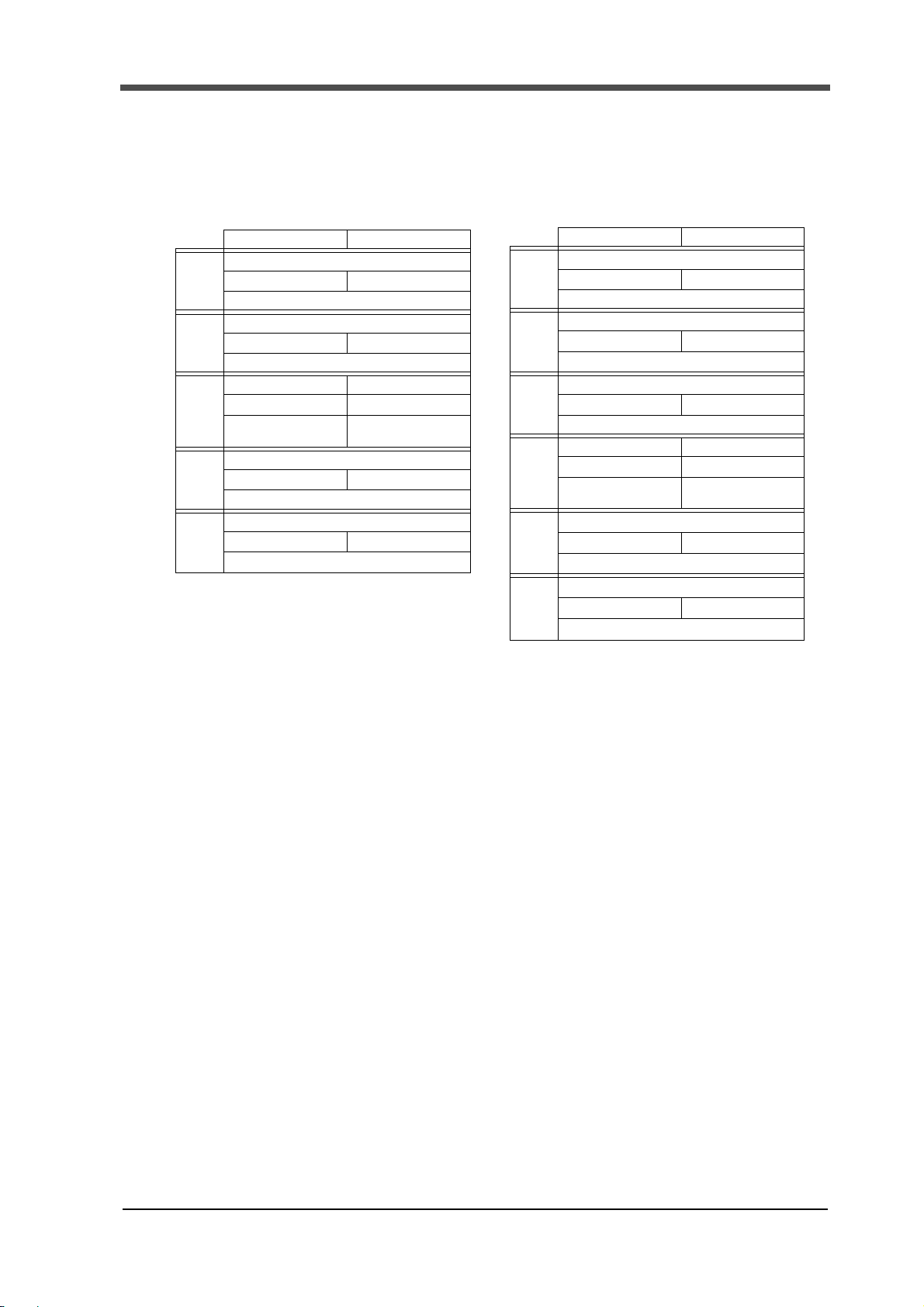
Alarm codes
The alarm codes appearing at the lower right of the DeviceNet setting
screen are as shown in the table below.
List of alarm codes
Code Status
0 Normal status
1 to 10 Internal hardware failure
11 Node address overlap
13 Network power failure
Correspondence between major revision and an EDS file
EDS
file
F381.eds 1 116 Only 0ch Approx. 30 sec.
F388.eds 1 115 Only 0ch Approx. 30 sec.
Major
revision
setting
Number
of
parameters
3. Communication connector
Remarks
Time to read via a
configurator
(at 500kbps)
Prepare a 24V DC power supply.
The relationship between each signal line and color chip is as follows.
The applicable plug is a PHENIX CONTACT-manufactured MSTB2.5/5-STF-5.08AUM
(accessory) or equivalent.
2
Page 8

4. Status LED
All input and output signals are of positive logic.
1: ON
0: OFF
The operations are the same as those of the I/O signals of
the main body. For details, refer to the F381A/F388A Operation Manual.
Point
Communication status is displayed by LED.
MS:Indicating the F381A/F388A status.
MS (Module status) LED Status
4.Status LED
Red Turns ON
Red Blinks
Green Blinks
Green Turns ON
NS:Indicating the Network status.
NS (Network status) LED Status
Red Turns ON
Red Blinks
Green Blinks
Green Turns ON
5. About remote I/O
The F381A/F388A can send status and indicated values through DeviceNet with a delay of approx.
100msec compared with external I/O signals of the main body (in simple remote I/O
communications).
Furthermore, the delay time is affected by the cycle time of the communications, scan time of the
PLC, etc.
Therefore, for cases where the speed is severe, use the control connector of the main body, and not
via communications.
In a line manner, since input signals such as the D/Z command also cause a delayed time when used
via communications, use the control connector for cases requiring speed.
Input signals (F381A/F388A → Master) are output to communications and the control connector in
parallel irrespective of settings of the main body.
For output signals. (Master → F381A/F388A), communications or the control connector can be
selected on a block-by-block basis.
Trouble
Trouble
Trouble
Normal
Bus OFF, Node Address Overlap
Communication Time-out
Waiting for Connection establishment
Normal
3
Page 9

6.I/O format
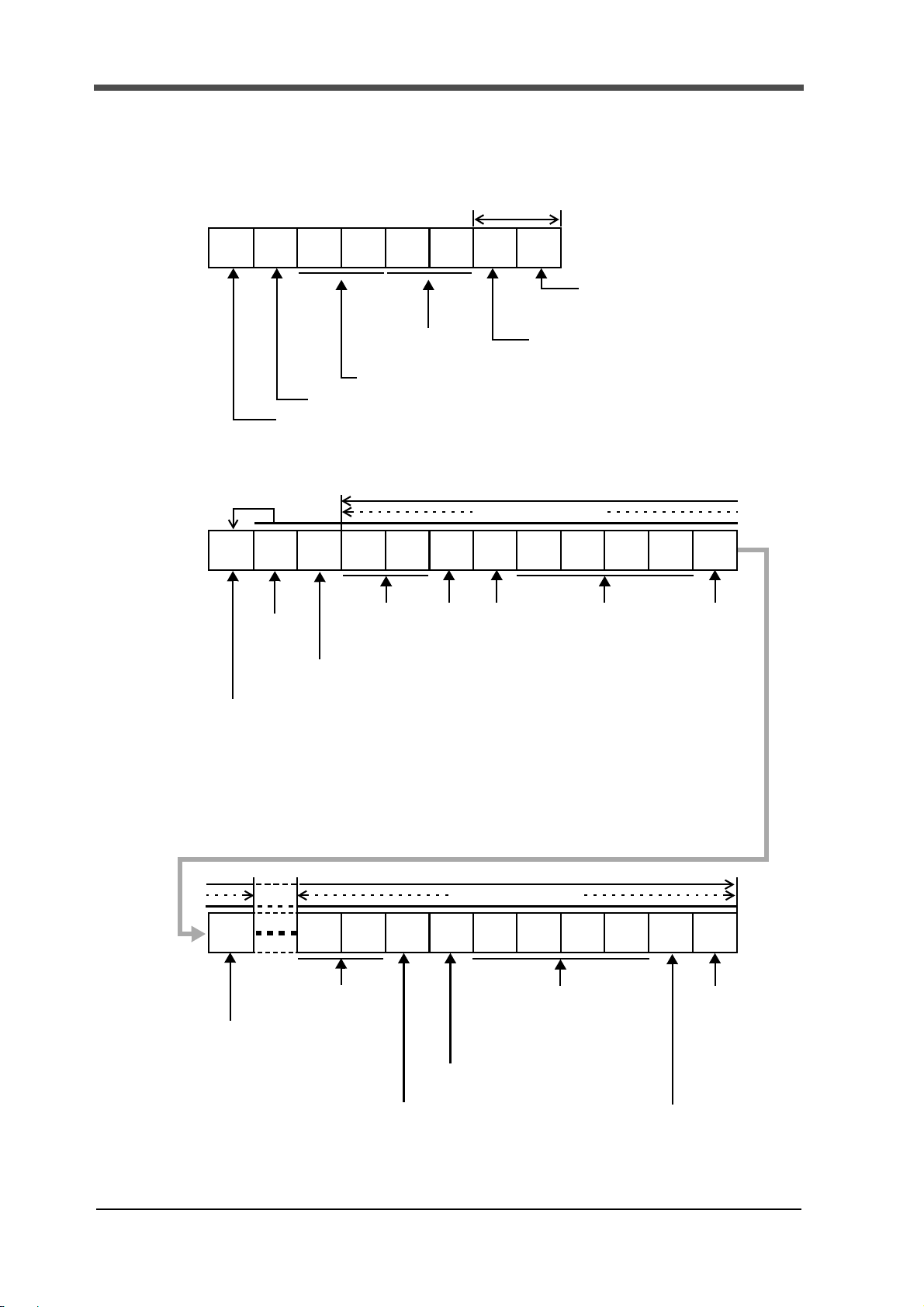
■Input data (F381A/F388A→Master)
■Output data (Master→F381A/F388A)
ch B15 B14 B13 B12 B11 B10 B9 B8 B7 B6 B5 B4 B3 B2 B1 B0
n+0
Load (Signed 16 bit binary)
n+1
DPM (Signed 16 bit binary)
n+2
SD
OK
DPM
OK
Load
OK
Run
Compl-
ete
Wave Result
Overload
Hold Result
DPM Load
HI OK LO HI OK LO HI OK LO
n+3
Work Display Measurement Status
8421
Reset
ON
Compl-
ete
Wai t
Cal.
Sampl-
ing
Wait
Lv.
Wait
OFF
Wai t
St.
ch B15 B14 B13 B12 B11 B10 B9 B8 B7 B6 B5 B4 B3 B2 B1 10
n+0
Work Prohibit
Touch
Panel
Back-
light
ON
Reset Hold Stop Start
DPM
Position
ing
Load
Digital
Zero
8421
* If speed is required, use the control connector on the main unit.
Effective only when Input Select 1 is Network.Effective only when Input Select 2
is Network.
6. I/O format 6-1.I/O format
4
Page 10

6-2.About input data
Load ・displacement
The data of the currently indicated value is stored. If the indicated value is held, the held value is
displayed.
* If the X-axis of the waveform is time, the displacement value becomes 0.
6.I/O format
Range
・Hold Result (Load/DPM)
・Overload
・Complete
・Wave Result
Load:-9999~9999、Displacement:-9999~320000
Use it for acquiring judgment results by using the hold function. If displacement needs to be
judged, also use DPM. It is not used if the hold function is not used. Hold results are output.
LO: Turns ON when the hold result falls below the LO limit, and the output is held.
HI: Turns ON when the hold result exceeds the HI limit, and the output is held.
OK: Turns ON when judgment is made during measurement and the LO and HI outputs are
not ON after completion of the measurement. OK will not turn ON if no hold is made
for the specified Number of Use Sections.
* Please fetch the inputs in synchronization with the Complete of n+2.
Use Overload to stop the equipment in case of emergency due to the excess load applied to the
sensor. Irrespective of the measurement status, it turns ON at the Overload. It turns OFF, when
the Overload is released.
Use it for recognizing the completion of measurement. It turns ON when the measurement is
completed.
Use it for acquiring judgment results by using the waveform comparison function. It is not used
if the waveform comparison function is not used. Waveform comparison results are output.
LO: Turns ON when the waveform comparison result falls below the LO limit, and the
output is held.
HI: Turns ON when the waveform comparison result exceeds the HI limit, and the output is
held.
OK: Turns ON when the Compare Area is passed through during measurement and the LO
and HI outputs are not ON after completion of the measurement. OK will not turn ON if
the measurement does not reach the Compare Area or the Reference Point of Relative
Comparison when Relative Comparison is made.
* Please fetch the inputs in synchronization with the Complete of n+2.
・Load OK
Use it for recognizing the abnormality of the load sensor. It is normally ON. It turns OFF with a
sensor error (sensor ±error), or display error (±OVER), or when load exceeds the Overload or
when the Load-Digital-Zeroed value exceeds the Digital Zero Limit. It also turns OFF when the
Start, Reset, or Load Digital Zero signal is ON.
・DPM OK
Use it if the X-axis of the waveform represents displacement. It is not used when the X-axis of
the waveform represents time. It turns OFF when measuring points of 10 data or more are
skipped because the pacing of displacement is too fast. It also turns OFF when the Start, Reset,
or DPM Positioning signal is ON.
5
Page 11

6.I/O format
Measurement status
・Run
Use it for confirming that the CPU is running normally.
When the CPU is running normally, switching between ON and OFF is done about every 0.5
sec. If it is ON or OFF for a few seconds, there may be something wrong.
・SD OK
Normally use it if the SD card slot option is used. It turns OFF with a memory card error*
when the measurement start input OFF →ON is ignored because a measurement waveform is
not saved in time while being saved automatically*
signal is ON.
*1 It does not turn ON until the error is cleared.
*2 It is reset by starting measurement being saved in time.
Displays the present measurement status.
Wait St............... The Start signal input is waited for. Input the Start signal. Measurement can
also be started by pressing the Start key.
Wait Off .............It is waited for that the Start signal input is turned OFF. Turn OFF the Start
signal.
Wait Lv. .............It is waited for that load or displacement crosses the Measurement Start Level.
Apply load to the sensor so as to cross the Measurement Start Level.
Sampling........... Measurement is in progress. The measurement is stopped when the
Measurement Stop Condition is met.
* During measurement, the present measurement waveform is not displayed.
Calculating ....... Judgment is being prepared.
Complete.......... Measurement is completed. The measurement waveform is displayed.
Reset On .......... It is waited for that the Reset signal is turned OFF.
2
. It also turns OFF when the Start or Reset
1
, or
Work display
The currently used work No. is output. During measurement, the work No. used for measurement is
output.
6-3.About output data
Load Digital Zero
Perform Digital Zero by unloading the load sensor before measurement to simply adjust the
deviation of the zero point of the load by temperature drift, etc. The load is zeroed by turning the
signal from OFF to ON. As long as the signal is ON, the Load OK output is kept OFF.
* Digital zero value is cleared when the power supply is turned on.If you want to
maintain digital zero value, please do zero calibration instead.
DPM Positioning
Use it for adjusting the zero point of displacement just before measurement start.
It is not used if the X-axis of the waveform represents time or the zero point of displacement does
not need to be adjusted. By turning the signal from OFF to ON, displacement is brought to the DPM
Positioning set value, and the internal counter of the pulse input is cleared. As long as the signal is
ON, the DPM OK output is kept OFF.
6
Page 12

7.About message communications
Start
Use it for starting measurement. By turning the signal from OFF to ON when the Start signal input
is waited for, a “Wait Off” state is brought about, and the Hold Result, Wave Result, Complete,
Load OK, and DPM OK outputs are turned OFF. By turning the signal from ON to OFF, a “Wait
Lv.” State is brought about, or the measurement is started according to the Measurement Start
Condition.
Stop
Use it for stopping measurement. By turning the signal from OFF to ON during measurement, the
measurement is stopped.
Hold
Use only for using the section control function by External Input. It is not used if the hold function
is not used or Change of Section is made by Setting. By turning the signal from OFF to ON, the
hold section is changed.
Reset
Use it for releasing some errors, etc., in emergencies. Irrespective of the measurement status, by
turning the signal from OFF to ON, the Hold Result, Wave Result, Load OK, and DPM OK outputs
are turned OFF, and a “Wait St.” state is brought about. If the Reset signal is turned from OFF to
ON during measurement, the measurement is forcedly stopped and the measurement data is
annulled. For keeping the data, check the data after completion of the measurement, and then turn
the Reset signal from OFF to ON.
Prohibit Touch Panel
Use it for controlling so as to prevent touch panel operations. As long as the signal is ON, no operation
can be performed with the touch panel.
Backlight On
Use it for controlling the backlight externally. By turning the signal from OFF to ON, the backlight
lights up. As long as the signal is ON, the backlight stays ON.
Work
Use it for using two or more work Nos. It is not used if only work No. 0 is used. Specify work
No(s). to be used before measurement.
7. About message communications
By using message communications, the following can be read and written.
Be aware that the setting range varies depending on the settings of the main unit.
* For message communications, a master that can carry out message communications and CPU unit
need to be combined.
・Set value: Read / Write / Read (all) / Write (all)
・Measurement range: Read
・Waveform: Read / Write
・Hold result: Read
・Wave No.: Read / Write
7
Page 13

8.Message communication
* For class ID, instance ID, attribute ID, and data, see List of set value commands
" ■ Read and write various settings" on page 17.
* Received data in normal condition is shown. For received data in abnormal
condition, see "Error response" on page16.
Point
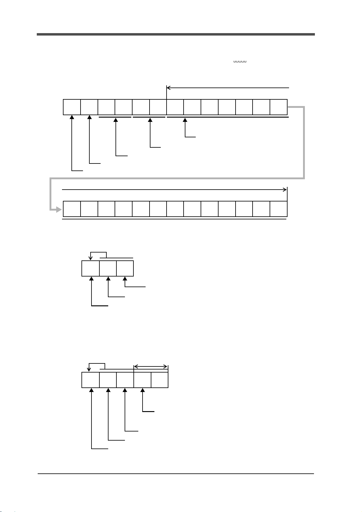
00H 0EH 00H 71H 00H 70H 67H
Node address (Node0)
Service code(Various setting reading)
Class ID (Hold setting)
Instance ID (work1、section2)
Attribute ID (Use hold)
Service data(1byte)
06H 00H 8EH 02H 00H 00H 00H
Receiving number of bytes(6byte)
Node address (Node0)
Service code+80H(Various setting reading)
Data(00000002H:PEAK)
Service data(4byte)
LL LH HL HH
8. Message communication
8-1.Communication format
■Reading set values
Example) Reading Use Hold in Hold Setting (work 1, section 2)
●Sending data(Master→F381A/F388A)
●Receiving data(F381A/F388A→Master)
8
Page 14

■Writing set values
00H 10H 00H 71H 00H 70H 67H
Node address (Node0)
Service Code(Various setting writing )
Class ID (Hold setting)
Data
Service data(5byte)
LL LH HL HH
02H 00H 00H 00H
(00000002H:Peak)
Instance ID (work1、section2)
Attribute ID(Use hold)
02H 00H 90H
Receiving number of bytes(2byte)
Node address (Node0)
Service Code+80H(Various setting writing )
00H 32H 00H 6FH 00H 6EH
Node address (Node0)
Service code(Various setting all reading)
Class ID (Measurement start condition setting)
Instance ID (work1)
12H 00H B2H 01H 00H 00H 00H
Receiving number of bytes
Node address (Node0)
Service code+80H (Various setting all reading)
Data4
Service data
LL LH HL HH
2CH 01H 00H
(0000012CH:300)
Data1measurement start condition
00H
LL LH HL HH
(00000001H:External Input + Load)
Measurement end level
(The number of bytes of service data+2
(Example is18byte))
(differs according to the class ID specified at send-time(Example is16byte))
Example) Writing Use Hold in Hold Setting (work 1, section 2)
●Sending data(Master→F381A/F388A)
●Receiving data(F381A/F388A→Master)
8.Message communication
■Reading set values(all)
Example) Reading all measurement start condition settings (work 1)
●Sending data(Master→F381A/F388A)
●Receiving data(F381A/F388A→Master)
9
Page 15

8.Message communication
00H 33H 00H 6FH 00H 64H 01H
Node address (Node0)
Service code (Various setting all writing )
Service data
00H 00H
Data1 measurement start condition
LL LH HL HH
(00000001H:External Input + Load)
00H
Class ID (Measurement start condition setting)
Instance ID (work0)
2CH 00H 00H
Data4 measurement end level
LL LH HL HH
(00000012H:300)
01H
(It changes with Class ID to specify. (Example is16byte))
02H 00H B3H
Receiving number of bytes(2byte)
Node address (Node0)
Service code+80H(Various setting all writing )
00H 34H 00H 82H 00H 64H
Node address (Node0)
Service code(Reading measurement range)
Class ID (0082H fixed)
Instance ID (0064H fixed)
■Writing set values(all)
Example) Writing all measurement start condition settings (work 0)
●Sending data(Master→F381A/F388A)
●Receiving data(F381A/F388A→Master)
■Reading measurement range
Example) Reading the measurement range
●Sending data(Master→F381A/F388A)
10
Page 16

8.Message communication
06H 00H B4H 00H 00H FFH 07H
Receiving number of bytes(6byte)
Node address (Node0)
Service code+80H (Reading measurement range)
Service data(4byte)
Data1 start of the range
LHLH
(0000H:0(Data number ))
data range:0 ~ 2047
Data2 end of the range.
(07FFH:2047(Data number ))
data range:0 ~ 2047
00H 35H 00H 82H 00H 64H 64H
Node address
Service code
Service data(6byte)
00H 00H 00H 1FH 00H
LHLHLH
(Node0)
(Reading
Class ID (Measured waveform)
・0082H(130):Measured waveform
・0083H(131):Comparison waveform (upper limit)
・0084H(132):Comparison waveform (lower limit)
・0085H(133):Comparison waveform (upper limit) used
for measurement
・0086H(134):Comparison waveform (lower limit) used
for measurement
Data3Data1 Data2
Instance ID
・0064H(100):work0
・006EH(110):work1 ~
00 FB H (2 50 ):work15
* Specify 0064H if a measurement
waveform or comparison waveform
used for measurement is specified
to class ID.
Data1(load)
・0064H(100):load
・0065H(101):Displacement(Time)
Data2 start of the range
(0000H:0(Data number )
data range:0 ~ 2047
* Data range should be as the start of the
range ≦ the end of the range.
* The end of the range - the start of the range
≦ 31.
Data3 end of the range.
(001FH:31(Data number )
data range:0 ~ 2047
waveform)
●Receiving data(F381A/F388A→Master)
■Reading waveform
A waveform is an array of up to 2048 (data No. 0 - 2047) load data. The data of the waveform can
be read by specifying the data No. range to read.
However, the amount of load data that can be handled in one message communication is up to 32.
The waveform is divided into 64 (32×64 = 2048), and the waveform is read 64 times.
* The range to read can be specified as narrowed by reading the measurement range.
(Depending on usage, all of 2048 may not be used for measurement.)
* The time required to read one waveform (load) (2048 data) is approximately 4 seconds.
・Measurement conditions:
CPU unit: SYSMAC CS1G CPU42-V1 (manufactured by OMRON)
Master unit: DeviceNet master unit CS1W-DRM21 (manufactured by OMRON)
Master and slave (F381A/F388A) one-to-one, 500kbps
No processing other than waveform read
Example) Reading a measurement waveform (load in the range of 0 - 2047)
① Read the measurement waveform in the range of 0 - 31.
●Sending data(Master→F381A/F388A)
11
Page 17

8.Message communication
42H 00H B5H FFH FFH 01H 00H
Receiving number of bytes
Service code+80H
Service data(differs according to the range specified at send-time
03H 00H 04H 00H
(The number of bytes of service data +2
LH LHLH
LH
Load:2nbyte Displacement(Time):4n (n=1 ~ 32(Example is n=32))
Node address
(Node0)
(Reading waveform)
Data1
Waveform data of the start of
the range(FFFFH:-1)
data range:-9999 ~ 9999
Data2
Waveform Data of the start of
the range+1(0001H:1)
data range:-9999 ~ 9999
Data1 Data2
Data n - 1Data n
Data n - 1
Waveform data of the end of
the range-1 (0003H:3)
data range:-9999 ~ 9999
Data n
Waveform data of the end of
the range.(0004H:4)
data range:-9999 ~ 9999
(Example is 66byte))
82H 00H B5H 00H 00H 00H 00H
Receiving number of bytes
Service code+80H
Service data(differs according to the range specified at send-time
1FH 00H 00H 00H
(The number of bytes of service data + 2
Load:2nbyte Displacement(Time):4n (n=1 ~ 32(Example is n=32))
Node address
(Node0)
(Reading waveform)
Waveform data of the start of the
range(00000000H:0)
data range:
・Time:0 ~ 51175
・Displacement(reference; front):
0 ~ 10235
・Displacement(reference; back):
-10235 ~ 0
Data1
Data n
Waveform data of the end of the
range.(0000001FH:31)
data range:
・Time:0 ~ 51175
・Displacement(reference; front):
0 ~ 10235
・Displacement(reference; back):
-10235 ~ 0
LL LH HL HH LL LH HL HH
(Example is 130byte))
●Receiving data(F381A/F388A→Master)
・When load is specified to data 1 of send data
・When Displacement is specified as data 1 of sending data
② Change the range and repeat ①. (the start of the range~last:32~63、64~95、…、
2016~2047)
12
Page 18

8.Message communication
00H 36H 00H 83H 00H 64H 64H
Node address
Service code
Service data (6byte)
00H 00H 00H 64H 00H
LHLHLH
(Node0)
(Writing waveform)
Class ID(Comparison waveform upper limit)
・0083H(131):Comparison waveform (upper limit)
・0084H(132):Comparison waveform (lower limit)
Data3Data1(0064H fixed)
Data2
Instance ID(Work 0)
・0064H(100):Work 0
・006EH(110):Work 1
~ 00FBH(250):Work 15
Data number specification
(0000H:0(Data No.))
Data range:0 ~ 2047
Load(0064H:100)
Data range:-9999 ~ 9999
02H 00H B6H
Receiving number of bytes(2byte)
Node address (Node0)
Service code +80H(Writing waveform)
■Writing waveform
A comparison waveform upper limit (lower limit) is an array of 2048 (data No: 0 - 2047) load data.
The comparison waveform is written by specifying data Nos. and load, and one piece of load data is
rewritten in one message communication. Therefore, for rewriting all of one waveform, writing
operation is to be performed 2048 times.
Example) Rewriting the comparison waveform upper limit (work 0)
① Writing to data No. 0 of the comparison waveform upper limit (work 0)
●Sending data(Master→F381A/F388A)
●Receiving data(F381A/F388A→Master)
② Change the start of the range and repeat ①. (Data number specification:1、2、…、
2047)(Load:as desired)
13
Page 19
8.Message communication
00H 40H 00H 8CH 00H 64H 65H
Node address (Node0)
Class ID (008CH fixed)
Data2 section last(section 5)
Service data (2byte)
69H
data range:65H(100)section1 ~
Instance ID
Data1 Section head(section1)
data range:65H(100)section 1 ~
Service code (Writing waveform)
69H(105)section5
* The data range should be as
the start of the range ≦ the end of the range.
69H(105) section 5
(0064H fixed)
Section head (section1)
02H C8H 00H 01H 03H B0H 00H 00H04H 01H 02H
34H 00H C0H FFH FFH 01H 01H
Node address
01H 00H
LL LH HL HH
2CH
LL LH HL HH
Service data (10n byte n=1 ~ 5 (Example is n=5))
Receiving number of bytes
(Number of bytes of Service data+2
(Node0)
Service code +80H
(Reading the hold results)
00H 01H
LH
Data1
Hold value(load)(FFFFH:-1)Data range:-9999 ~ 9999
Data2
Existence of load Data(Existent)
・0:None ・1:Existent
Data3
Load judging (OK)
・0:Unused ・1:OK・2:HI・3:LO・4:H/L・5:NG
Data4
Hold value(Time or displacement )(0000012CH:300 (Example is
displacement)
)Data range:・Time:0 ~ 51175
・Displacement(reference; front):0 ~ 10235
・Displacement(reference; back):- 10235 ~ 0
Data5
Existence of Displacement Data(Existent)
・0:None ・1:Existent
Data1 Data2 Data3 Data4 Data5
Displacement judging(HI)
・0:Unused 3:LO
・1:OK 4:H/L
・2:HI 5:NG
Data6
Data6
Data5
Data4
Hold value(Time or displacement )
(000004B0H:1200
(Example is displacement))
Data3
Data2
LH
Data1
Hold value(load)
Load judging (HI)
(00C8H:200)
Load judging (LO)
Existence of load data
(Existent)
Existence of displacement data
(Existent)
(Example is 52byte))
Section head (section1)
Section last (section5)
■Reading hold results
Example) Reading the hold results of section 1 to section 5 (X-axis: displacement)
●Sending data(Master→F381A/F388A)
●Receiving data(F381A/F388A→Master)
14
Page 20

■Reading Wave No.
00H 44H 00H 96H 00H 64H
Node address (Node0)
Service code (Reading Wave No.)
Class ID (0096H fixed)
Instance ID (0064H fixed)
109 12 1114 1316151817 2019 th byte
16H 00H C4H
30H 32H 32H 31H
Data
30H 31H35H
Service data(20 byte fixed)
Receiving number of bytes(22byte)
Service code +80H (Reading Wave No.)
33H
214 36 587 th byte
'0' '2' '2' '1' '5' '0' '1' '3'
Node address (Node0)
data range:0、20 ~ 7E、80 ~ FCH
30H 5FH 30H 30H 30H 30H 20H 20H 20H31H 20H
'0' '_' '0' '0' '0' '0' ' ' '1' ' ' ' ' ' ' ' '
20H
Example) Reading the Wave No. (when "20120531_000001 " is set)
●Sending data(Master→F381A/F388A)
●Receiving data(F381A/F388A→Master)
8.Message communication
15
Page 21
8.Message communication
'0' '2' '2' '1' '5' '0' '1'
7 10 9 12 11 14 13 16 15 18 17 20 19 th byte
00H 45H 00H 96H 00H 64H 30H 32H 31H32H
Service data(20 byte fixed)
Node address (Node0)
Class ID (0096H fixed)
35H
214 36 58th byte
Service code (Writing Wave No.)
33H 30H 5FH 30H 30H 30H 30H 31H 20H20H 20H
'3' '0' '_' '0' '0' '0' '0' ' ' '1' ' ' ' ' ' ' ' '
20H
30H 31H
20H
Instance ID (0064H fixed)
Data
data range:20 ~ 7E、80 ~ FCH
02H 00H C5H
Receiving number of bytes(2byte)
Node address (Node0)
Service code +80H(Writing Wave No.)
04H 00H 94H 16H FFH
Receiving number of bytes(4byte)
Node address (Node0)
Service code (94H fixed)
Service data(2byte)
Error number
Error number
・16H: Class ID is wrong.
Instance ID is wrong.
・08H: Instance ID is 00.
Service code is wrong.
・20H: Service code is 80H or more.
・14H: Attribute ID is wrong.
・15H: Large number of service data
・13H: Small number of service data
・10H: Writing was attempted with the lock applied.
Writing was attempted during measurement.
Write data is wrong (out of range).
■Writing Wave No.
Example) Writing the Wave No. (for setting "20120531_000001 ")
●Sending data(Master→F381A/F388A)
●Receiving data(F381A/F388A→Master)
■Error response
Common to received data
●Receiving data(F381A/F388A→Master)
16
Page 22

8.Message communication
( ① F381A ② F388A)
8-2. List of set value commands
■Read and write various settings
Service code Class ID Instance ID Attribute ID Input range (display range)
・Read V
Settings
Get Attribute
Single
0EH
・Write
Settings
Set Attribute
Single
10H
arious
Var i o us
Y- a xi s
Setting
0065H (101)
0064H (100) 64H
(100)
65H
(101)
66H
(102)
68H
(104)
69H
(105)
6AH
(106)
6BH
(107)
6CH
(108)
6DH
(109)
6EH
(110)
①Exc. Voltage
②Input Select
Unit
Decimal Place
Equiv. Cal.
(rated output)
Equiv. Cal.
(rated capacity)
Overload 0 to 9999
Increment
Analog Filter
Digital Filter 0, 2 to 999 [Times]
DZ Limit 0 to 9999
①0:2.5 1:10 [V]
②0:±10V 1:±20mA
See "■Unit setting list" on page 24.
0:01:0.0
2:0.00 3:0.000
①-9.999 to 9.999 [mV/V]
②-99.99 to 99.99 [V, mA]
-9999 to 9999
0:11:2
2:53:10
0:10 1:30
2:100 3:300 [Hz]
17
Page 23

8.Message communication
Service code Class ID Instance ID Attribute ID Input range (display range)
Read Various
・
Settings
Get Attribute
Single
0EH
・Write
Var i o u s
Settings
Set Attribute
Single
10H
X-axis
Setting
(DPM)
0066H (102)
Communication
Setting
0067H (103)
0064H (100) 64H
(100)
65H
(101)
66H
(102)
67H
(103)
68H
(104)
6AH
(106)
6BH
(107)
6CH
(108)
6DH
(109)
6EH
(110)
6FH
(111)
0064H (100)
64H
(100)
65H
(101)
66H
(102)
67H
(103)
68H
(104)
69H
(105)
6AH
(106)
6BH
(107)
Time/DPM
Change
Phase Select
Wave Reference
Unit
Decimal Place
Equiv. Cal.
(number of pulses)
(voltage value)
Equiv. Cal.
(displacement
value)
Measure Length
DPM Positioning -9999 to 32000
Analog Filter
(Only ①)
Digital Filter 0, 2 to 999 [Times]
Speed
Data Bit
Parity Bit
Stop Bit
Delimiter
Header
Flow Control
Com. Mode
0:Time
1:Displacement
0:A/B-Phase
1:Only A-Phase
0:Front 1:Back
See "■Unit setting list" on page 24.
0:01:0.0
2:0.00 3:0.000
Standard 1 to 1000000
When the voltage input option is used
-9.999 to 9.999 [V] (Only ①)
-99999 to 99999
Time/Displacement Change; Time
0:0.5 1:1.0 2:2.0
3:5.0 4:10.0 [s]
Time/Displacement Change;
Displacement
0:2000 1:4000 2:6000
3:8000 4:10000
0:10 1:30
2:100 3:300 [Hz]
0:1200 1:2400
2:4800 3:9600
4:19.2k 5:38.4k [bps]
0:71:8 [bit]
0:None 1:Even
2:Odd
0:11:2 [bit]
0:CR 1:CR+LF
0:None 1:STX
0:Off
1:RTS/CTS Control
0:Normal
1:Hold Point Mode
18
Page 24

8.Message communication
Service code Class ID Instance ID Attribute ID Input range (display range)
Read Various
・
Settings
Get Attribute
Single
0EH
・Writ e
Va r i ou s
Settings
Set Attribute
Single
10H
System
0068H (104)
Option
Measurement
Start
Condition
Setting
006FH (111)
Display
Range Setting
0070H (112)
0064H (100) 64H
(100)
65H
(101)
66H
(102)
67H
(103)
68H
(104)
69H
(105)
0064H (100)
006EH (110)
to
00FBH (250)
0064H (100)
006EH (110)
to
00FBH (250)
Work 0
Work 1
to
Work 15
Work 0
Work 1
to
Work 15
64H
(100)
65H
(101)
66H
(102)
67H
(103)
64H
(100)
65H
(101)
66H
(102)
67H
(103)
Backlight
(ON Time)
Language
Work P r o t e c t
First Protect
Contrast 100 (Bright) to 170 (Dark)
Backlight
(Bright → Dark)
Start Condition
Start Level
Stop Condition
Stop Level
Y Start Point -10000 to 10000
Y End Point
X Start Point
X End Point
0 to 99 [minute]
0:Japanese
1:English
0:Not Protect
1:Protect
0:Not Protect
1:Protect
0 to 99 [minute]
0: Only External Input
1: External Input + Load
2: External Input + Displacement
(2 can be set only when the X-axis of
the waveform represents displacement.)
External Input + Load: -9999 to +9999
External Input + Displacement:
-9999 to +32000
0: Only Forced-Stop
1: Load 2: Time
3: Displacement 4: Displacement Stop
(3 and 4 can be set only when the X-axis of
the waveform represents displacement.)
Load: -9999 to +9999
Time: 0.1 to 10.0 [second]
Displacement: -9999 to +32000
Displacement Stop: 0.1 to 10.0 [second]
Y-axis Start Point +
0:25 1:50 2:100 3:200
4:300 5:400 6:500
7:1000 8:2000 9:3000
10:4000 11:5000
12:10000 13:20000
Time or displacement (Front)
0 to 2000 (× Measurement Length/2000)
Displacement (Back)
-2000 to 0 (× Measurement Length/2000)
Time or displacement (Front)
X-axis Start Point +
0:25 1:50 2:100
3:200 4:400 5:600
6:800 7:1000 8:1200
9:1400 10:1600 11:1800
12:2000 13:2200
(× Measurement Length/2000)
Displacement (Back)
X-axis Start Point +
0:
-25 1:-50 2:-100
3:-200 4:-400 5:-600
6:-800 7:-1000 8:-1200
9:-1400 10:-1600 11:-1800
12:-2000 13:-2200
(× Measurement Length/2000)
19
Page 25

8.Message communication
Service code Class ID Instance ID Attribute ID Input range (display range)
Read Various
・
Settings
Get Attribute
Single
0EH
・Writ e
Var i ou s
Settings
Set Attribute
Single
10H
Hold Setting
0071H (113)
0065H (101)
0066H (102)
0067H (103)
0068H (104)
0069H (105)
006FH (111)
0070H (112)
0071H (113)
0072H (114)
0073H (115)
to
00FFH (255)
Work 0 (Sct 1)
Work 0 (Sct 2)
Work 0 (Sct 3)
Work 0 (Sct 4)
Work 0 (Sct 5)
Work 1 (Sct 1)
Work 1 (Sct 2)
Work 1 (Sct 3)
Work 1 (Sct 4)
Work 1 (Sct 5)
to
Work 15 (Sct 5)
64H
(100)
65H
(101)
67H
(103)
68H
(104)
69H
(105)
6AH
(106)
6BH
(107)
6CH
(108)
6DH
(109)
6EH
(110)
6FH
(111)
Change of Sct.
(common to all
work)
Use Sct. 1 to 5
Use Hold
Sct. Start-End
(start point)
Note1)
Sct. Start-End
(end point)
Note1)
Load HI/LO Limit
(HI) Note1)
Load HI/LO Limit
(LO) Note1)
DPM HI/LO
Limit
(HI)
Note1)
DPM HI/LO
Limit
(LO)
Note1)
Start Load -9999 to 9999
Load Difference 1 to 19998
0: External Input 1: Setting
(0 can be set only
when the time or displacement (Front))
0: Always 1: Sample
2: Peak 3: Bottom
4: Peak to Peak
5: Relative Maximum
6: Relative Minimum
7: Inflection Point
8: Average
9: End Displacement
Time or displacement (Front)
0 to 2047 (× Measurement Length/2000)
* However, End point of the previous section
≦Start point≦End point
Displacement (Back)
-2047 to 0 (× Measurement Length/2000)
* However, End point of the previous section
≧Start point≧End point
Time or displacement (Front)
0 to 2047 (× Measurement Length/2000)
* However, Start point≦End point
≦Start point of the next section
Displacement (Back)
-2047 to 0 (× Measurement Length/2000)
* However, Start point≧End point
≧Start point of the next section
-9999 to +9999
* Setting HI limit < LO limit is unacceptable.
-9999 to +9999
* Setting HI limit < LO limit is unacceptable.
Waveform Reference; Front
0 to 2047 (× Measurement Length/2000)
Waveform Reference; Back
-2047 to 0 (× Measurement Length/2000)
* When End Displacement in Use Hold
is selected; -9999 to 32000
* Setting HI limit < LO limit is unacceptable.
Waveform Reference; Front
0 to 2047 (× Measurement Length/2000)
Waveform Reference; Back
-2047 to 0 (× Measurement Length/2000)
* When End Displacement in Use Hold
is selected; -9999 to 32000
* Setting HI limit < LO limit is unacceptable.
20
Page 26

8.Message communication
Service code Class ID Instance ID Attribute ID Input range (display range)
Read Various
・
Settings
Get Attribute
Single
0EH
・Write
Various
Settings
Set Attribute
Single
10H
Hold Setting
0071H (113)
Waveform
Comparison
Setting
0072H (114)
Calibration
0078H (120)
0065H (101)
0066H (102)
0067H (103)
0068H (104)
0069H (105)
006FH (111)
0070H (112)
0071H (113)
0072H (114)
0073H (115)
to
00FFH (255)
0064H (100)
006EH (110)
to
00FBH (250)
0064H (100) 64H
Work 0 (Sct 1)
Work 0 (Sct 2)
Work 0 (Sct 3)
Work 0 (Sct 4)
Work 0 (Sct 5)
Work 1 (Sct 1)
Work 1 (Sct 2)
Work 1 (Sct 3)
Work 1 (Sct 4)
Work 1 (Sct 5)
to
Work 15 (Sct 5)
Wor k 0
Wor k 1
to
Wor k 15
70H
(112)
71H
(113)
72H
(114)
73H
(115)
64H
(100)
65H
(101)
66H
(102)
67H
(103)
68H
(104)
69H
(105)
(100)
65H
(101)
66H
(102)
67H
(103)
0: 1/4 1: 1/2 2: 3/4
Rate
Ordinal 1 to 15 [Times]
Interval AB (A) 1 to 999 (× Measurement Length/2000)
Interval AB (B) 1 to 999 (× Measurement Length/2000)
Relative
Compare Area
(start point)
Note1)
Compare Area
(end point)
Note1)
Compare Margin 0 to 999
Relative Point
(X-axis)
Relative Point
(Y-axis)
Zero Cal. (load) Fixed at 0
Zero Cal.
(displacement)
Actual Cal. (load) -9999 to 9999
Actual Cal.
(displacement)
3: 1 4: 1.25 5: 1.5
6: 1.75 7: 2 8: 3 9: 4[Times]
0:Off 1:On
Time or displacement (Front)
0 to 2047 × Measurement Length/2000
* Setting Start point > End point is unacceptable.
Displacement (Back)
-2047 to 0 × Measurement Length/2000
* Setting Start point < End point is unacceptable.
Time or displacement (Front)
0 to 2047 × Measurement Length/2000
* Setting Start point > End point is unacceptable.
Displacement (Back)
-2047 to 0 × Measurement Length/2000
* Setting Start point < End point is unacceptable.
Time or displacement (Front)
0 to 2047 (× Measurement Length/2000)
Displacement (Back)
-2047 to 0 (× Measurement Length/2000)
-9999 to 9999
Fixed at 0
-9999 to 32000
21
Page 27

8.Message communication
Note1)
Please change other set values beforehand so that the setting range
becomes the maximum when a set value to which other settings influence the
setting range is written in.
Example 1 When you write the Load HI Limit value in.
Please write -9999 in the Load LO Limit value beforehand.
Example 2 When you change the Section Start-End.
Please write 2047(Time or Displacement (Front)) and -2047(Displacement
(Back)) in of the start point and the end point in all sections beforehand in
order of End Point of Section 5, Start Point of Section 5, End Point of
Section 4, …… End Point of Section 1 and Start Point of Section 1.
Please write in the value to be set in order of Start Point of Section 1, End
Point of Section 1, Start Point of Section 2, …… Start Point of Section 5
and End Point of Section 5.
Point
22
Page 28

■All read & write set values
8.Message communication
Service code Class ID Instance ID
・All Read Various
Settings
32H
・
All Write
Settings
33H
Var i o us
Y-axis Setting
0065H (101)
X-axis Setting
(DPM)
0066H (102)
Communication
Setting
0067H (103)
System
0068H (104)
Option
Measurement
Start Condition
Setting
006FH (111)
Display Range
Setting
0070H (112)
0064H (100) 0 40 40 0
0064H (100) 0
0064H (100) 0 32 32 0
0064H (100) 0 20 20 0
0064H (100)
006EH (110)
to
00FBH (250)
0064H (100)
006EH (110)
to
00FBH (250)
Wor k 0
Wor k 1
to
Wor k 15
Wor k 0
Wor k 1
to
Wor k 15
Number of bytes
of service data
All read All write
sending receiving sending receiving
44 (F381A)
40 (F388A)
016160
016160
Number of bytes
of service data
44 (F381A)
40 (F388A)
0
Hold Setting
0071H (113)
Waveform
Comparison
Setting
0072H (114)
0065H (101)
0066H (102)
0067H (103)
0068H (104)
0069H (105)
006FH (111)
0070H (112)
0071H (113)
0072H (114)
0073H (115)
to
00FFH (255)
0064H (100)
to
0073H (115)
Wor k 0 (S ct 1)
Wor k 0 (S ct 2 )
Wor k 0 (S ct 3 )
Wor k 0 (S ct 4 )
Wor k 0 (S ct 5 )
Wor k 1 (S ct 1)
Wor k 1 (S ct 2 )
Wor k 1 (S ct 3 )
Wor k 1 (S ct 4 )
Wor k 1 (S ct 5 )
to
Wor k 1 5 (S ct 5 )
Wor k 0
to
Wor k 15
060600
024240
23
Page 29

8.Message communication
■Unit setting list
* Numbers are values of input range.
Also, “0” results in no unit.
①F381A
Weight Force Pressure Length Angle Other
1 μg 11 μN 24 μPa 41 μm 48 rad 51 g/cm
2 mg 12 mN 25 mPa 42 mm 49 ° 52 kg/m
3 g 13 N 26 Pa 43 cm 50 deg 53 t/m
4 kg 14 kN 27 hPa 44 m 54 g/l 88 μA
5 Mg 15 MN 28 kPa 45 km 55 g/ml 89 mA
6 t 16 μNm 29 MPa 46 in 56 mg/m 90 A
7 lb 17 mNm 30 GPa 47 ft 57 kg/m 91 kA
8 dyne 18 Nm 31 N/m
2
58 kgm/s 92 μV
9 kdyne 19 kNm 32 μbar 59 kgm
10 oz 20 MNm 33 mbar 60 kgm
21 ftlb 34 bar 61 mPas 95 kV
22 inlb 35 mmHg 62 Pas 96 Ω
23 inoz 36 inH
O 63 m2/s 97 kΩ
2
37 ftH2O 64 mm/s 98 MΩ
38 psia 65 m/s 99 W
39 psig 66 mm/min 100 kW
40 atom 67 cm/min 101 MW
68 m/min 102 VA
69 m/h 103
70 km/h 104 °F
71 m/s
72 rpm 106 kJ
73 Hz 107 MJ
74 kHz 108
75 MHz 109 l
76 kg/s 11 0 m
77 t/s 111
78 kg/min 11 2 ‰
79 t/min 113 ppm
80 kg/h 11 4 pH
81 t/h 115 gcm
82 m
83 m3/min 117 TONNE
84 m
3
85 l/s
3
86 l/min
3
2
2
2
3
/s 116 kgcm
3
/h
87 l/h
/s 93 mV
94 V
105 J
℃
%RH
3
%
24
Page 30

8.Message communication
② F388A
Weight Force Pressure Length Angle Other
1 μg 11 μN 28 μPa 45 μm 52 rad 55 g/cm
2 mg 12 mN 29 mPa 46 mm 53 ° 56 kg/m
3 g 13 N 30 Pa 47 cm 54 deg 57 t/m
4 kg 14 kN 31 hPa 48 m 58 g/l 92 μA
5 Mg 15 MN 32 kPa 49 km 59 g/ml 93 mA
6 t 16 μNm 33 MPa 50 in 60 mg/m 94 A
7 lb 17 mNm 34 GPa 51 ft 61 kg/m 95 kA
8 dyne 18 Nm 35 N/m
2
62 kgm/s 96 μV
9 kdyne 19 kNm 36 μbar 63 kgm
10 oz 20 MNm 37 mbar 64 kgm
21 ftlb 38 bar 65 mPas 99 kV
22 inlb 39 mmHg 66 Pas 100 Ω
23 inoz 40 inH
24 Ncm 41 ftH
O 67 m2/s 101 kΩ
2
O 68 mm/s 102 MΩ
2
25 gcm 42 psia 69 m/s 103 W
26 kgcm 43 psig 70 mm/min 104 kW
27 kgm 44 atom 71 cm/min 105 MW
72 m/min 106 VA
73 m/h 107
74 km/h 108 °F
75 m/s
76 rpm 110 kJ
77 Hz 111 MJ
78 kHz 11 2
79 MHz 113 l
80 kg/s 11 4 m
81 t/s 11 5
82 kg/min 116 ‰
83 t/min 11 7 ppm
84 kg/h
85 t/h
86 m
87 m
88 m3/h
3
89 l/s
3
90 l/min
3
3
/s
3
/min
2
91 l/h
2
/s 97 mV
2
98 V
109 J
℃
%RH
%
3
25
Page 31

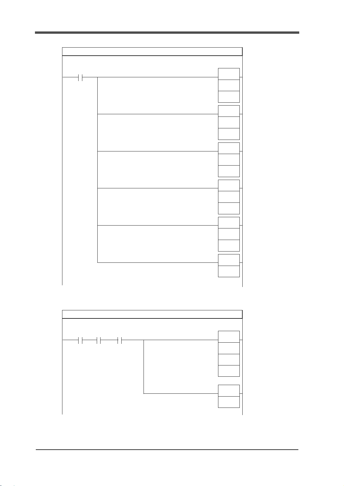
9.A sample program of message communications using
9. A sample program of message communications
using
OMRON-manufactured PLC and CS1 is shown.
Messages are transmitted when the execution condition (4.00 = 1) is met as sending FINS
commands and send data are stored in advance (D000 and later, D100 and later).
Received data is stored in D200 and later.
This sample program has been created by the following conditions:
・CPU unit: SYSMAC CS1G CPU42-V1 (manufactured by OMRON)
・Master unit: DeviceNet master unit CS1W-DRM21 (manufactured by OMRON)
・Master node address: 63
・Slave (F381A/F388A) node address: 0
・Number of send data: 9H, stored in D000
・Number of received data: 136D: Set the maximum number of received data in
consideration of error messages.
・Sending FINS command data: D000 and later
・Send data storage area: D100 and later
・Received data storage area: D200 and later
・Service code: '0EH (reading of various set values)
・Class ID: '0071H: (Hold Setting)
・Instance ID: '0070H (work 1, section 2)
・Attribute ID (service data): '67H (Use Hold)
26
Page 32

9-1.Program
* 1
P_First_Cycle
D29999
of sending data
* 2
receiving data
Target network
address = 0
(Home network address)
Target
node address
=
3FH、(63
)
Target machine
Response required,
communications port,
number of retransmissions
Response monitoring time
Communications initial setting 1
A200.11
Operation start
BSET
(071)
#0
D0
MOV
(021)
#9
D0
MOV
(021)
&136
D1
MOV
(021)
#0
D2
MOV
(021)
#3FFE
D3
MOV
(021)
#0000
D4
MOV
(021)
#0064
D5
0
0
1Cycle ON
address = FEH
Number of bytes
Number of bytes of
Network-connected unit
Example)Reading set values
9.A sample program of message communications using
"Reading set values" is mention as an example.
About the program of the contents of other message communications, it is possible to correspond
by changing D000 and D100 or subsequent ones.(Please refer to "9-2The representative case of
each message in a sample program" on page 29.)
27
Page 33
9.A sample program of message communications using
* 3Description of
P_First_Cycle
Node address = 00、
Service code = 0EH
Class ID = 0064H
Instance ID
Attribute ID
Communications initial setting 2, Command data
A200.11
Operation start
MOV
(021)
#2801
D100
MOV
(021)
#000E
D101
MOV
(021)
#0071
D102
MOV
(021)
#0070
D103
MOV
(021)
#6700
D104
SET
4.00
1
8
Command code
= 0064H
= 64H
1Cycle ON
sending data
Execution condition
= 2801H fixed
(as desired)
Explicit Send message
4.00
Network
CMND
(490)
D100
D200
ASL
(025)
4
2
15
Send message
D0
Online
A202.00 1511.00
communications state
executable
Execution
condition
28
Page 34

9.A sample program of message communications using
Retry
4.01
MOV
(021)
A203
D6
ASR
(026)
4
3
20
A202.00 A219.00
END
(001)
4
25
Network Network
communications communications
executable execution error
* Received data in normal condition is shown. For received data in abnormal
condition, see " ■ Error response" on page 40.
Point
Sending data(CPU → Master(F381A/F388A))
High Low
D000
Number of bytes of sending data
00H 09H
9byte
D100
Command code
28H 01H
FINS Command
D101
Node address Service code
00H 0EH
Node0
Various setting
reading
D102
Class ID
00H 71H
Hold setting
D103
Instance ID
00H 70H
Work1、section2
D104
Attribute ID
---
67H
00H
Use hold ---
Receiving data(Master(F381A/F388A)→CPU)
High Low
D200
Command code
28H 01H
FINS Command
D201
Completion code
00H 00H
Normal end:(refer to FINS Command)
D202
Number of bytes of receiving data
00H 06H
6byte
D203
Node address Service code
00H 8EH
Node0
Various setting
reading
D204
Data :Use hold(LL、HH)
02H 00H
00000002H:Peak
D205
Data :Use hold(HL、HH)
00H 00H
9-2.
The representative case of each message in a sample
program
■Reading set values
Example) Reading Use Hold in Hold Setting (work 1, section 2)
29
Page 35

9.A sample program of message communications using
Sending data(CPU → Master(F381A/F388A))
High Low
D000
Number of bytes of sending data
00H 0DH
13byte
D100
Command code
28H 01H
FINS Command
D101
Node address Service code
00H 10H
Node0 Various setting writing
D102
Class ID
00H 71H
Hold setting
D103
Instance ID
00H 70H
Work1、section2
D104
Attribute ID DATA(LL)
67H 02H
Use hold
00000002H:PEAK
D105
DATA(LH、HL)
00H 00H
D106
DATA(HH)
---
00H
00H
---
Receiving data(Master(F381A/F388A) → CPU)
High Low
D200
Command code
28H 01H
FINS Command
D201
Completion code
00H 00H
Normal end:(refer to FINS Command)
D202
Number of bytes of receiving data
00H 02H
2byte
D203
Node address Service code
00H 90H
Node0 Various setting writing
■Writing set values
Example) Writing Use Hold in Hold Setting (work 1, section 2)
30
Page 36

9.A sample program of message communications using
Sending data(CPU → Master(F381A/F388A))
High Low
D000
Number of bytes of sending data
00H 08H
8byte
D100
Command code
28H 01H
FINS Command
D101
Node address Service code
00H 32H
Node0
Various setting all
reading
D102
Class ID
00H 6FH
Measurement start condition setting
D103
Instance ID
00H 6EH
Work1
Receiving data(Master(F381A/F388A)→ CPU)
High Low
D200
Command code
28H 01H
FINS Command
D201
Completion code
00H 00H
Normal end:(refer to FINS Command)
D202
Number of bytes of receiving data
00H 12H
18byte
D203
Node address Service code
00H B2H
Node0
Various setting all
reading
D204
Data1:Measurement start condition
(LL、LH)
01H 00H
00000001H:External Input + Load
D205
Data1:Measurement start condition
(HL、HH)
00H 00H
・
・
・
・
・
・
D210
Data4:Measurement end level (LL、LH)
2CH 01H
0000012CH:300
D211
Data4:Measurement end level (HL、HH)
00H 00H
■Reading set values(all)
Example) Reading all measurement start condition settings (work 1)
31
Page 37
9.A sample program of message communications using
Sending data(CPU → Master(F381A/F388A))
High Low
D000
Number of bytes of sending data
00H 18H
24byte
D100
Command code
28H 01H
FINS Command
D101
Node address Service code
00H 33H
Node0
Various setting all
writing
D102
Class ID
00H 6FH
Measurement start condition setting
D103
Instance ID
00H 64H
Work0
D104
Data1:Measurement start condition
(LL、LH)
01H 00H
00000001H:External Input + Load
D105
Data1:Measurement start condition
(HL、HH)
00H 00H
・
・
・
・
・
・
D110
Data4:Measurement end level (LL、LH)
2CH 01H
0000012CH:300
D111
Data4:Measurement end level (HL、HH)
00H 00H
Receiving data(Master(F381A/F388A) → CPU)
High Low
D200
Command code
28H 01H
FINS Command
D201
Completion code
00H 00H
Normal end:(refer to FINS Command)
D202
Number of bytes of receiving data
00H 02H
2byte
D203
Node address Service code
00H B3H
Node0
Various setting all
writing
■Writing set values(all)
Example) Writing all measurement start condition settings (work 0)
32
Page 38
9.A sample program of message communications using
Receiving data(Master(F381A/F388A) → CPU)
High Low
D200
Command code
28H 01H
FINS Command
D201
Completion code
00H 00H
Normal end:(refer to FINS Command)
D202
Number of bytes of receiving data
00H 06H
6byte
D203
Node address Service code
00H B4H
Node0
Reading
measurement range
D204
Data1:Measurement start condition(L、H)
00H 00H
0000H:0
D205
Data2:End of the range(L、H)
FFH 07H
07FFH:2047
Sending data(CPU → Master(F381A/F388A))
High Low
D000
Number of bytes of sending data
00H 08H
8byte
D100
Command code
28H 01H
FINS Command
D101
Node address Service code
00H 34H
Node0
Reading
measurement range
D102
Class ID
00H 82H
0082Hfixed
D103
Instance ID
00H 64H
0064Hfixed
■Reading measurement range
Example) Reading the measurement range
33
Page 39
9.A sample program of message communications using
Sending data(CPU → Master(F381A/F388A))
High Low
D000
Number of bytes of sending data
00H 0EH
14byte
D100
Command code
28H 01H
FINS Command
D101
Node address Service code
00H 35H
Node0 Reading waveform
D102
Class ID
00H 82H
Measured waveform
D103
Instance ID
00H 64H
D104
Data1:(L、H)
64H 00H
load
D105
Data2:Start of the range(L、H)
00H 00H
0
D106
Data3:End of the range.(L、H)
1FH 00H
31
Receiving data(Master(F381A/F388A) → CPU)
High Low
D200
Command code
28H 01H
FINS Command
D201
Completion code
00H 00H
Normal end:(refer to FINS Command)
D202
Number of bytes of receiving data
00H 42H
66byte (2n+2)
D203
Node address Service code
00H B5H
Node0 Reading waveform
D204
Data1:
Waveform data of the start of the range(L、H)
FFH FFH
FFFFH:- 1
D205
Data2:
Waveform data of the start of the range+1(L、H)
01H 00H
0001H:1
・
・
・
・
・
・
D234
(D203
+n-1)
Data n-1:
Waveform data of the end of the range-1(L、H)
03H 00H
0003H
D235
(D203
+n)
Data n:
Waveform data of the end of the range(L、H)
04H 00H
0004H
* n:1 ~ 32 "End of the range." - "Start of the range" + 1
■Reading waveform
Example) Reading Measured waveform(Load、Range 0~31)
34
Page 40

9.A sample program of message communications using
Sending data(CPU → Master(F381A/F388A))
High Low
D000
Number of bytes of sending data
00H 0EH
14byte
D100
Command code
28H 01H
FINS Command
D101
Node address Service code
00H 36H
Node0 Writing waveform
D102
Class ID
00H 83H
Comparison waveform upper limit
D103
Instance ID
00H 64H
Work0
D104
Data1:(L、H)
64H 00H
Load
D105
Data2:Start of the range(L、H)
00H 00H
0
D106
Data3:Load(L、H)
64H 00H
0064H:100
Receiving data(Master(F381A/F388A) → CPU)
High Low
D200
Command code
28H 01H
FINS Command
D201
Completion code
00H 00H
Normal end:(refer to FINS Command)
D202
Number of bytes of receiving data
00H 02H
2byte
D203
Node address Service code
00H B6H
Node0 Writing waveform
■Writing waveform
Example) Rewriting the comparison waveform upper limit (work 0)
35
Page 41

9.A sample program of message communications using
Sending data(CPU → Master(F381A/F388A))
High Low
D000
Number of bytes of sending data
00H 0AH
10byte
D100
Command code
28H 01H
FINS Command
D101
Node address Service code
00H 40H
Node0
Reading the hold
results
D102
Class ID
00H 8CH
008CH fixed
D103
Instance ID
00H 64H
0064H fixed
D104
Data1:Section head Data2:Section last
65H 69H
Section1 Section5
■Reading the hold results
Example) Reading the hold results of section 1 to section 5 (X-axis: displacement)
36
Page 42

9.A sample program of message communications using
High Low
・
・
・
・
・
・
D224
(D199
+5n)
Data1:Hold value(Load)(L、H)
C8H 00H
00C8H:200
D225
(D200
+5n)
Data2:Existence of
load Data
Data3:Load judging
01H 03H
Existent LO
D226
(D201
+5n)
Data4:
Hold value(Time or displacement )(LL、LH)
B0H 04H
000004B0H:1200
D227
(D202
+5n)
Data4:
Hold value(Time or displacement )(HL、HH)
00H 00H
D228
(D203
+5n)
Data5:
Existence of
Displacement Data
Data6:
Displacement judging
01H 02H
Existent HI
* n:1 ~ 5 "Section last" - "Section head" + 1
High Low
D200
Command code
28H 01H
FINS Command
D201
Completion code
00H 00H
Normal end:(refer to FINS Command)
D202
Number of bytes of receiving data
00H 34H
52byte(10n+2)
D203
Node address Service code
00H C0H
Node0
Reading the hold
results
D204
Data1:Hold value(Load)(L、H)
FFH FFH
FFFFH:- 1
D205
Data2:
Existence of load Data
Data3:Load judging
01H 01H
Existent OK
D206
Data4:
Hold value(Time or displacement )(LL、LH)
2CH 01H
0000012CH:300
D207
Data4:
Hold value(Time or displacement )(HL、HH)
00H 00H
D208
Data5:
Existence of
Displacement Data
Data6:
Displacement judging
01H 02H
Existent HI
・
・
・
・
・
・
Section
last
Section
head
Receiving data(Master(F381A/F388A)→CPU)
37
Page 43

9.A sample program of message communications using
Receiving data(Master(F381A/F388A)→ CPU)
High Low
D200
Command code
28H 01H
FINS Command
D201
Completion code
00H 00H
Normal end:(refer to FINS Command)
D202
Number of bytes of receiving data
00H 16H
22byte
D203
Node address Service code
00H C4H
Node0 Reading Wave No.
D204
2th byte 1th byte
30H 32H
'0' '2'
D205
4th byte 3th byte
32H 31H
'2' '1'
D206
6th byte 5th byte
35H 30H
'5' '0'
D207
8th byte 7th byte
31H 33H
'1' '3'
D208
10th byte 9th byte
30H 5FH
'0' '_'
D209
12th byte 11th byte
30H 30H
'0' '0'
D210
14th byte 13th byte
30H 30H
'0' '0'
D211
16th byte 15th byte
20H 31H
' ' '1'
D212
18th byte 17th byte
20H 20H
' ' ' '
D213
20th byte 19th byte
20H 20H
' ' ' '
Sending data(CPU → Master(F381A/F388A))
High Low
D000
Number of bytes of sending data
00H 08H
8byte
D100
Command code
28H 01H
FINS Command
D101
Node address Service code
00H 44H
Node0 Reading Wave No.
D102
Class ID
00H 96H
0096H fixed
D103
Instance ID
00H 64H
0064H fixed
■Reading Wave No.
Example) Reading the Wave No. (for setting "20120531_000001 ")
38
Page 44

9.A sample program of message communications using
Receiving data(Master(F381A/F388A) → CPU)
High Low
D200
Command code
28H 01H
FINS Command
D201
Completion code
00H 00H
Normal end:(refer to FINS Command)
D202
Number of bytes of receiving data
00H 02H
2byte
D203
Node address Service code
00H C5H
Node0 Writing Wave No.
Sending data(CPU → Master(F381A/F388A))
High Low
D000
Number of bytes of sending data
00H 1CH
2byte
D100
Command code
28H 01H
FINS Command
D101
Node address Service code
00H 45H
Node0 Writing Wave No.
D102
Class ID
00H 96H
0096H fixed
D103
Instance ID
00H 64H
0064H fixed
D104
2th byte 1th byte
30H 32H
'0' '2'
D105
4th byte 3th byte
32H 31H
'2' '1'
D106
6th byte 5th byte
35H 30H
'5' '0'
D107
8th byte 7th byte
31H 33H
'1' '3'
D108
10th byte 9th byte
30H 5FH
'0' '_'
D109
12th byte 11th byte
30H 30H
'0' '0'
D110
14th byte 13th byte
30H 30H
'0' '0'
D111
16th byte 15th byte
20H 31H
' ' '1'
D112
18th byte 17th byte
20H 20H
' ' ' '
D113
20th byte 19th byte
20H 20H
' ' ' '
■Writing Wave No.
Example) Writing the Wave No. (for setting "20120531_000001 ")
39
Page 45

10.Device profiles and object implementation
Receiving data(Master(F381A/F388A) → CPU)
High Low
D200
Command code
28H 01H
FINS Command
D201
Completion code
00H 00H
Normal end:(refer to FINS Command)
D202
Number of bytes of receiving data
00H 04H
4byte
D203
Node address Service code
00H 94H
Node0 94H fixed
D204
Error code
16H FFH
Error number
FFH fixed
■Error response
Example) Class ID is wrong.(Error number:16H)
10.Device profiles and object implementation
(①F381A ②F388A)
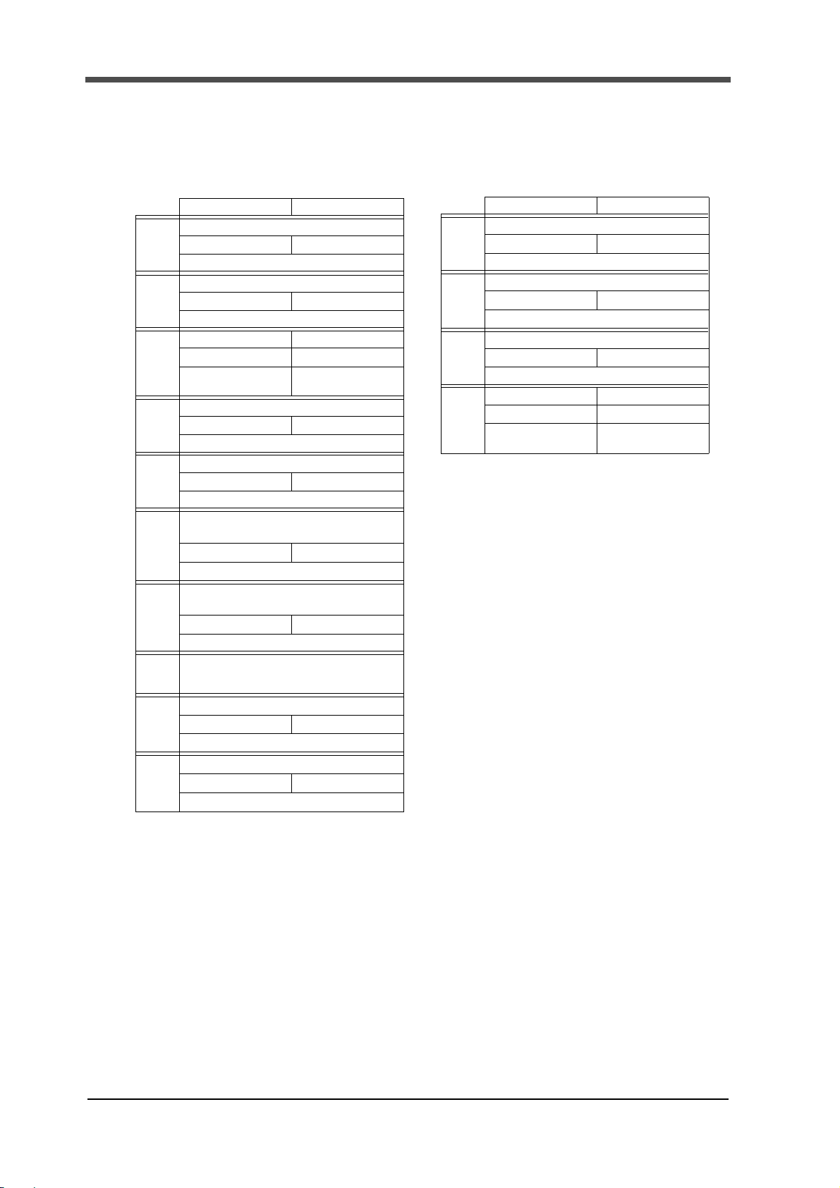
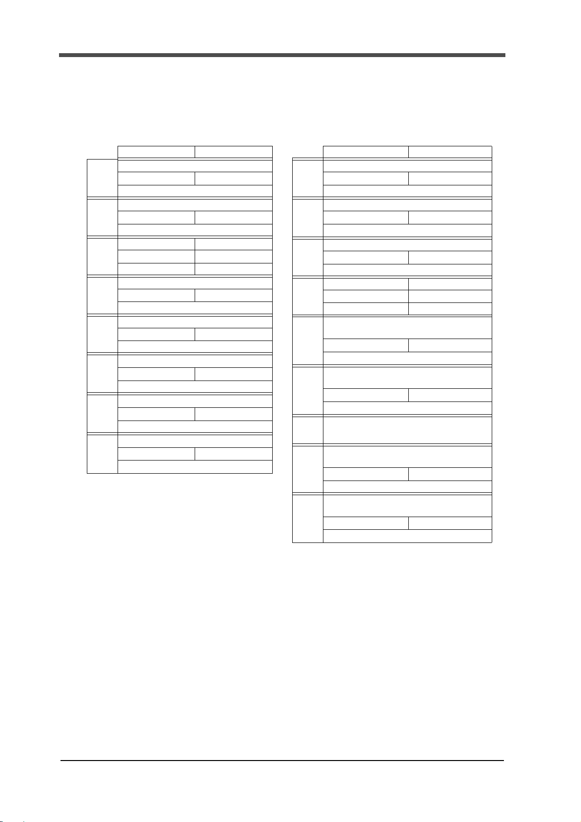
■Device profiles
General data Corresponding Specification for DeviceNet
Vender ID 135
Device type Generic device type No:0
Produce code
Physical
conformance
data
Current consumption by net work About 30mA (at DC24V)
Connector type The open plug type
With or without insulation for physical layer The use of insulation
Supported LED Module
MAC ID setting Setting by touch panel
Default MAC ID 00
Transmission baud rate setting Not available (Automatic follow-up to the master.)
Supported baud rate 125kbit/s, 250kbit/s, 500kbit/s
Predefined master/ slave connection set Group 2 only server
Support for dynamic connection (UCMM) Not available
Fragmentation of explicit message Available
Communication
data
40
Vo l u m e 1 Release2.0
Vo l u m e 2 Release2.0
①9 ②16
Network
Page 46

10.Device profiles and object implementation
■Implementation of objects
Identity object (01H)
Object class Attribute Not supported
Service Not supported
Object
instance
Attribute ID description GET SET Value
1 Vendor ○
2 Device type ○
3 Product code ○
4 Revision
5 Status (bits supported) ○
6 Serial number ○
7 Product name
8 State
Configuration Consistency Value
9
10 Heartbeat Interval
Service DeviceNet service Parameter option
05H Reset
0EH Get_Attribute_Single
○
○
Not available
Not available
×135
×0
×
×
× bit 0 only
× Each unit
×
××
××
××
(Varying depending on the set value.)
①F381
②F388
Message router object (02H)
Object class Attribute Not supported
Service Not supported
Object instance Attribute Not supported
Service Not supported
Addition of vendor-specific
specification
Not available
①9 ②16
01, 02H or 02, 02H
41
Page 47

10.Device profiles and object implementation
DeviceNet objects (03H)
Objects class Attribute ID description GET SET Value
1 Revision ○
Service DeviceNet service Parameter option
0EH Get_Attribute_Single
Not available
× 02H
Object
instance
Attribute ID description GET SET Value
1 MAC ID ○○
2 Baud rate ○○
3 BOI ○
4 Bus-off counter ○
5 Allocation information ○
6 MAC ID switch changed
7 Baud rate switch changed
8 MAC ID switch value
9 Baud rate switch value
Service DeviceNet Service Parameter option
0EH Get_Attribute_Single
10H Set_Attribute_Single
4BH Allocate Master/
Slave_Connection Set
4CH Release Master/
Slave_Connection Set
××
××
××
××
Not available
Not available
Not available
Not available
Assembly object (04H)
Object class Attribute Not supported
Service Not supported
× 00H
×
×
Object
instance
100
Object
instance
101
42
Section Information Max. number of instances
Instance type Static I/O 1
Attribute Description GET SET Value
1 Number of Members in List
2 Member List
3 Data ○○
Service DeviceNet service Parameter option
0EH Get_Attribute_Single
10H Set_Attribute_Single
Section Information Max. number of instances
Instance type Static I/O 1
Attribute Description GET SET Value
1 Number of Members in List
2 Member List
3 Data ○
Service DeviceNet service Parameter option
0EH Get_Attribute_Single
××
××
Not available
Not available
××
××
×
Not available
Page 48

10.Device profiles and object implementation
Connection object (05H)
Object class Attribute Not supported
Service Not supported
Max. number of active
connections
1
Object
Instance
Section Information Max. number of instances
1
Instance type Explicit Message 1
Production
trigger
Transport type Server
Transport class 3
Attribute ID description GET SET Value
Service DeviceNet service Parameter option
Cyclic
1 State ○
2 Instance type ○
3 Transport class trigger ○
4 Produced connection ID ○
5 Consumed connection ID ○
6 Initial comm. characteristics ○
7 Produced connection size ○
8 Consumed connection size ○
9 Expected packed rate ○○
12 Watchdog time-out action ○○
Produced connection path length
13
14 Produced connection path ○
Consumed connection path length
15
16 Consumed connection path ○
17 Production inhibit time ○
05H Reset
0EH Get_Attribute_Single
10H Set_Attribute_Single
○
○
Not available
Not available
Not available
×
× 00H
× 83H
×
×
× 21H
× 64H
× 64H
× 00H
×
× 00H
×
×
One of 01, 03
43
Page 49

10.Device profiles and object implementation
Object
Instance
Section Information Max. number of instances
2
Instance type Polled I/O 1
Production
trigger
Transport type Server
Transport class 2
Attribute ID description GET SET Value
Service DeviceNet service Parameter option
Cyclic
1 State ○
2 Instance type ○
3 Transport class trigger ○
4 Produced connection ID ○
5 Consumed connection ID ○
6 Initial comm. characteristics ○
7 Produced connection size ○
8 Consumed connection size ○
9 Expected packed rate ○○
12 Watchdog time-out action ○
Produced connection path length
13
14 Produced connection path ○
Consumed connection path length
15
16 Consumed connection path ○
17 Production inhibit time ○
05H Reset
0EH Get_Attribute_Single
10H Set_Attribute_Single
Not available
Not available
Not available
×
× 01H
× 82H
×
×
× 01H
× 0800H
× 0400H
×00
× 06H
○
× 20_04_24_65_30_03
× 06H
○
× 20_04_24_64_30_03
×
Set value object (1) Y-axis Setting (65H)
Object class Attribute Not supported
Service Not supported
Object Instance 100
(setting ch0)
*For those other than
100, see "Object Instance
type" on page50.
Attribute ID description GET SET
64H ①Exc. Voltage ②Input Select ○○
65H Unit ○○
66H Decimal Place ○○
68H Equiv. Cal. (rated output) ○○
69H Equiv. Cal. (rated capacity) ○○
6AH Overload ○○
6BH Increment ○○
6CH Analog Filter ○○
6DH Digital Filter ○○
6EH DZ Limit ○○
Service DeviceNet service Parameter option
0EH Get_Attribute_Single
10H Set_Attribute_Single
32H All read
33H All write
Not available
Not available
Not available
Not available
44
Page 50

10.Device profiles and object implementation
Set value object (2) X-axis Setting (66H)
Object class Attribute Not supported
Service Not supported
Object Instance 100
(setting ch0)
*For those other than
100, see "Object Instance
type" on page50.
Set value object (3) communication setting (67H)
Attribute ID description GET SET
64H Time/DPM Change ○○
65H Phase Select ○○
66H Wave Reference ○○
67H Unit ○○
68H Decimal Place ○○
6AH Equiv. Cal. (rated output) ○○
6BH Equiv. Cal. (rated capacity) ○○
6CH Measure Length ○○
6DH DPM Positioning ○○
6EH Analog Filter (Only ①) ○○
6FH Digital Filter ○○
Service DeviceNet service Parameter option
0EH Get_Attribute_Single
10H Set_Attribute_Single
32H All read
33H All write
Not available
Not available
Not available
Not available
Object class Attribute Not supported
Service Not supported
Object Instance 100
(setting ch0)
*For those other than
100, see "Object Instance
type" on page50.
Attribute ID description GET SET
64H Speed ○○
65H Data Bit ○○
66H Parity Bit ○○
67H Stop Bit ○○
Delimiter ○○
68H
69H Header ○○
6AH Flow Control ○○
6BH Com. Mode ○○
Service DeviceNet service Parameter option
0EH Get_Attribute_Single
10H Set_Attribute_Single
32H All read
33H All write
Not available
Not available
Not available
Not available
45
Page 51

10.Device profiles and object implementation
Set value object (4) system setting (68H)
Object class Attribute Not supported
Service Not supported
Object Instance 100
(setting ch0)
*For those other than
100, see "Object Instance
type" on page50.
Attribute ID description GET SET
64H Backlight (ON Time) ○○
65H Language ○○
66H Work Protect ○○
67H First Protect ○○
68H Undefined ○○
69H Backlight (bright→dark) ○○
Service DeviceNet service Parameter option
0EH Get_Attribute_Single
10H Set_Attribute_Single
32H All read
33H All write
Set value object (5) measurement start condition setting (69H)
Object class Attribute Not supported
Service Not supported
Object Instance 100
(setting ch0)
*For those other than
100, see "Object Instance
type" on page50.
Attribute ID description GET SET
64H Start Condition ○○
65H Start Level ○○
66H Stop Condition ○○
67H Stop Level ○○
Service DeviceNet service Parameter option
0EH Get_Attribute_Single
10H Set_Attribute_Single
32H All read
33H All write
Not available
Not available
Not available
Not available
Not available
Not available
Not available
Not available
Set value object (6) Display Range Setting (70H)
Object class Attribute Not supported
Not supported
Object Instance 100
(setting ch0)
*For those other than
100, see "Object Instance
type" on page50.
46
Service
Attribute ID description GET SET
64H Y Start Point ○○
65H Y End Point ○○
66H X Start Point ○○
67H X End Point ○○
Service DeviceNet service Parameter option
0EH Get_Attribute_Single
10H Set_Attribute_Single
32H All read
33H All write
Not available
Not available
Not available
Not available
Page 52
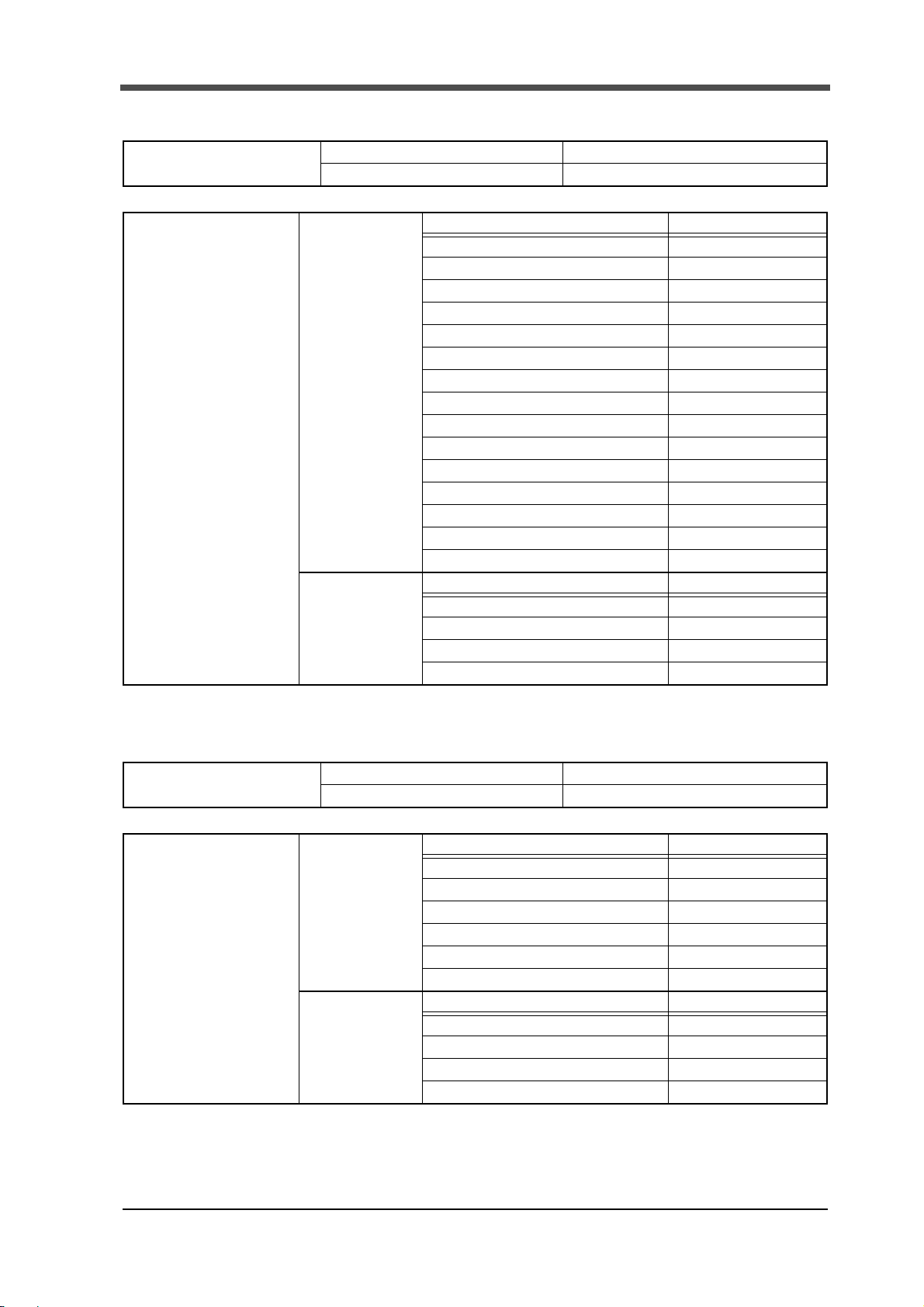
10.Device profiles and object implementation
Set value object (7) Hold Setting (71H)
Object class Attribute Not supported
Service Not supported
Object Instance 100
(setting ch0)
*For those other than
100, see "Object Instance
type" on page50.
Attribute ID description GET SET
64H Change of Sct. ○○
65H Use Sct. ○○
67H Use Hold ○○
68H Sct. Start-End (start point) ○○
69H Sct. Start-End (end point) ○○
6AH Load HI/LO Limit (HI) ○○
6BH Load HI/LO Limit (LO) ○○
6CH DPM HI/LO Limit (HI) ○○
6DH DPM HI/LO Limit (LO) ○○
6EH Start Load ○○
6FH Load Difference ○○
70H Rate ○○
71H Ordinal ○○
72H Interval AB (A) ○○
73H Interval AB (B) ○○
Service DeviceNet service Parameter option
0EH Get_Attribute_Single
10H Set_Attribute_Single
32H All read
33H All write
Not available
Not available
Not available
Not available
Set value object (8) Waveform Comparison Setting (72H)
Object class Attribute Not supported
Service Not supported
Object Instance 100
(setting ch0)
*For those other than
100, see "Object Instance
type" on page50.
Attribute ID description GET SET
Relative ○○
64H
65H Compare Area (start point) ○○
66H Compare Area (end point) ○○
67H Compare Magin ○○
68H Relative Point (X-axis) ○○
6AH Relative Point (Y-axis) ○ ○
Service DeviceNet service Parameter option
0EH Get_Attribute_Single
10H Set_Attribute_Single
32H All read
33H All write
Not available
Not available
Not available
Not available
47
Page 53

10.Device profiles and object implementation
Set value object (9) Calibration (78H)
Object class Attribute Not supported
Service Not supported
Object Instance 100
(setting ch0)
*For those other than
100, see "Object Instance
type" on page50.
Attribute ID description GET SET
64H Zero Cal. (load) ○○
65H Zero Cal. (displacement) ○○
66H Actual Cal. (load) ○○
67H Actual Cal. (displacement) ○○
Service DeviceNet service Parameter option
0EH Get_Attribute_Single
10H Set_Attribute_Single
Waveform object (1) Measurement waveform (82H)
Object class Attribute Not supported
Service Not supported
Object Instance 100
(setting ch0)
*For those other than
100, see "Object Instance
type" on page50.
Service DeviceNet service Parameter option
34H Read measurement range
35H Read waveform
Not available
Not available
Not available
Not available
Waveform object (2) Comparison waveform (HI limit) (83H)
Object class Attribute Not supported
Service Not supported
Object Instance 100
(setting ch0)
*For those other than
100, see "Object Instance
type" on page50.
Service DeviceNet service Parameter option
35H Read waveform
36H Write waveform
Waveform object (3) Comparison waveform (LO limit) (84H)
Object class Attribute Not supported
Service Not supported
Object Instance 100
(setting ch0)
*For those other than
100, see "Object Instance
type" on page50.
Service DeviceNet service Parameter option
35H Read waveform
36H Write waveform
Not available
Not available
Not available
Not available
48
Page 54

10.Device profiles and object implementation
Waveform object (4)
Comparison waveform used for measurement (HI limit) (85H)
Object class Attribute Not supported
Service Not supported
Object Instance 100
(setting ch0)
*For those other than 100,
see "Object Instance type"
on page50.
Service DeviceNet service Parameter option
35H Read waveform
Waveform object (5)
Comparison waveform used for measurement (LO limit) (86H)
Object class Attribute Not supported
Service Not supported
Object Instance 100
(setting ch0)
*For those other than 100,
see "Object Instance type"
on page50.
Service DeviceNet service Parameter option
35H Read waveform
Hold results object (8CH)
Not available
Not available
Object class Attribute Not supported
Service Not supported
Object Instance 100
(setting ch0)
*For those other than 100,
see "Object Instance type"
on page50.
Service DeviceNet service Parameter option
40H Read hold results
Wave No. object (96H)
Object class Attribute Not supported
Service Not supported
Object Instance 100
(setting ch0)
*For those other than 100,
see "Object Instance type"
on page50.
Service DeviceNet service Parameter option
44H Read wave No.
45H Write wave No.
Not available
Not available
Not available
49
Page 55

10.Device profiles and object implementation
Object Instance type
Sections not specified
100 (64H) Setting ch0 160 (A0H) Setting ch6 220 (DCH) Setting ch12
110 (6EH) Setting ch1 170 (AAH) Setting ch7 230 (E6H) Setting ch13
120 (78H) Setting ch2 180 (B4H) Setting ch8 240 (F0H) Setting ch14
130 (82H) Setting ch3 190 (BEH) Setting ch9 250 (FAH) Setting ch15
140 (8CH) Setting ch4 200 (C8H) Setting ch10
150 (96H) Setting ch5 210 (D2H) Setting ch11
Sections specified
Setting ch0 Setting ch1 Setting ch2
101 (65H) Sct 1 111 (6FH) Sct 1 121 (79H) Sct 1
102 (66H) Sct 2 112 (70H) Sct 2 122 (7AH) Sct 2
103 (67H) Sct 3 113 (71H) Sct 3 123 (7BH) Sct 3
104 (68H) Sct 4 114 (72H) Sct 4 124 (7CH) Sct 4
105 (69H) Sct 5 115 (73H) Sct 5 125 (7DH) Sct 5
Setting ch3 Setting ch4 Setting ch5
131 (83H) Sct 1 141 (8DH) Sct 1 151 (97H) Sct 1
132 (84H) Sct 2 142 (8EH) Sct 2 152 (98H) Sct 2
133 (85H) Sct 3 143 (8FH) Sct 3 153 (99H) Sct 3
134 (86H) Sct 4 144 (90H) Sct 4 154 (9AH) Sct 4
135 (87H) Sct 5 145 (91H) Sct 5 155 (B9H) Sct 5
Setting ch6 Setting ch7 Setting ch8
161 (A1H) Sct 1 171 (ABH) Sct 1 181 (B5H) Sct 1
162 (A2H) Sct 2 172 (ACH) Sct 2 182 (B6H) Sct 2
163 (A3H) Sct 3 173 (ADH) Sct 3 183 (B7H) Sct 3
164 (A4H) Sct 4 174 (AEH) Sct 4 184 (B8H) Sct 4
165 (A5H) Sct 5 175 (AFH) Sct 5 185 (B9H) Sct 5
Setting ch9 Setting ch10 Setting ch11
191 (BFH) Sct 1 201 (C9H) Sct 1 211 (D3H) Sct 1
192 (C0H) Sct 2 202 (CAH) Sct 2 212 (D4H) Sct 2
193 (C1H) Sct 3 203 (CCH) Sct 3 213 (D5H) Sct 3
194 (C2H) Sct 4 204 (CCH) Sct 4 214 (D6H) Sct 4
195 (C3H) Sct 5 205 (CDH) Sct 5 215 (D7H) Sct 5
Setting ch12 Setting ch13 Setting ch14
221 (DDH) Sct 1 231 (E7H) Sct 1 241 (F1H) Sct 1
222 (DEH) Sct 2 232 (E8H) Sct 2 242 (F2H) Sct 2
223 (DFH) Sct 3 233 (E9H) Sct 3 243 (F3H) Sct 3
224 (E0H) Sct 4 234 (EAH) Sct 4 244 (F4H) Sct 4
225 (E1H) Sct 5 235 (EBH) Sct 5 245 (F5H) Sct 5
Setting ch15
251 (FBH) Sct 1
252 (FCH) Sct 2
253 (FDH) Sct 3
254 (FEH) Sct 4
255 (FFH) Sct 5
50
Page 56

10.Device profiles and object implementation
( ①F381A ② F388A)
■Expression of EDS file and the explanation
Name of setting value
Class ID
Y-axis Setting
0065H (101)
X-axis Setting
(DPM)
0066H (102)
Communication
Setting
0067H (103)
System
0068H (104)
Attribute ID Expression of EDS file Explanation
64H (100)
65H (101) Unit Unit
66H (102) Decimal Place Decimal Place
68H (104) Equiv. Cal. Load (Out)
69H (105) Equiv. Cal. Load (Capacity)
6AH (106) Overload Overload
6BH (107) Increment Increment
6CH (108) Analog Filter Analog Filter
6DH (109) Digital Filter Digital Filter
6EH (110) DZ limit Digital Zero Limit
64H (100) Time/DPM change
65H (101) Phase Select
66H (102) Wave Reference
67H (103) Unit Unit
68H (104) Decimal Place Decimal Place
6AH (106) Equiv. Cal. DPM (Pulse/Volt)
6BH (107) Equiv. Cal. DPM (Value)
6CH (108) Measure Length Measurement Length
6DH (109) DPM Positioning Displacement Positioning
6EH (110)
6F H ( 111 ) Digital Filter Digital Filter
64H (100) Speed Transmission Speed
65H (101) Data Bit Data Bit
66H (102) Parity Bit Parity Bit
67H (103) Stop Bit Stop Bit
68H (104) Delimiter Delimiter
69H (105) Header Header
6AH (106) Flow Control Flow Control
6BH (107) Com. Mode Communication Mode
64H (100) Backlight (ON Time) Backlight
65H (101) Language Language
66H (102) Setting Protection Work Setting Parameter Protection
67H (103) Cal. Protection First Setting Parameter Protection
68H (104) Contrast Contrast
69H (105)
①Exc. Voltage
②Input Select
Analog Filter (Only ①) Analog Filter (Only ①)
Backlight (bright→dark)
①Excitiation Voltage
②Input Selection
Equivalent Input Calibration
(rated output)
Equivalent Input Calibration
(rated capacity)
Time/Displacement change ★
Sensor Phase Select ★
Waveform Reference ★
Equivalent Input Calibration
(number of pulses) (voltage value)
Equivalent Input Calibration
(displacement value)
Backlight
51
Page 57

10.Device profiles and object implementation
For the ★-marked settings, see "■Names of alternatives" on page 53.
Point
Class ID
Measurement
Start Condition
Setting
006FH (111)
Display Range
Setting
0070H (112)
Hold Setting
0071H (113)
Waveform
Comparison
Setting
0072H (114)
Calibration
0078H (120)
Attribute ID Expression of EDS file Explanation
64H (100) Start Condition
65H (101) Start Level Measurement Start Level
66H (102) Stop Condition
67H (103) Stop Level Measurement Stop Level
64H (100) Y Start Point Y-axis Start Point
65H (101) Y End Point Y-axis End Point
66H (102) X Start Point X-axis Start Point
67H (103) X End Point X-axis End Point
64H (100) Change of Sct.
65H (101) Use Sct. Number of Use Sections
67H (103) Use Hold
68H (104) Sct. Start-End (Start) Section Start-End (start point)
69H (105) Sct. Start-End (End) Section Start-End (end point)
6AH (106) Load HI/LO Limit (HI) Load HI/LO Limit (HI limit)
6BH (107) Load HI/LO Limit (LO) Load HI/LO Limit (LO limit)
6CH (108) DPM HI/LO Limit (HI) Displacement HI/LO Limit (HI limit)
6DH (109) DPM HI/LO Limit (LO) Displacement HI/LO Limit (LO limit)
6EH (110) Start Load Detection Start Load
6FH (111) Load difference Detection Load Difference
70H (112) Rate Detection Rate
71H (113) Ordinal Detection Ordinal
72H (114) Interval AB (A) Detection Interval AB (A)
73H (115) Interval AB (B) Detection Interval AB (B)
64H (100) Relative Relative Comparison
65H (101) Compare Area (Start) Compare Area (start)
66H (102) Compare Area (End) Compare Area (end)
67H (103) Compare Magin Compare Margin
68H (104) Relative Point (X)
69H (105) Relative Point (Y)
64H (100) Zero Cal. (Load) Zero Calibration (load)
65H (101) Zero Cal. (DPM) Zero Calibration (displacement)
66H (102) Actual Cal. (Load)
67H (103) Actual Cal. (DPM) Actual Load Calibration (displacement)
Measurement Start Condition ★
Measurement Stop Condition ★
Change of Section ★
Use Hold ★
Reference Point of Relative Comparison
(X-axis)
Reference Point of Relative Comparison
(Y-axis)
Actual Load Calibration (load)
52
Page 58

■Names of alternatives
10.Device profiles and object implementation
Set value
0 Time Time
1 DPM Displacement
Set value
0 A/B-Phase A/B-Phase
1 only A-Phase only A-Phase
Set value
0 Front Front
1 Back Back
Set value
0 Only Ext Only External Input
1 Ext + Load External Input + Load
2 Ext + DPM External Input + Displacement
Expression of EDS file Explanation
Time/DPM Change Time/Displacement Change
Expression of EDS file Explanation
Phase Select Sensor Phase Select
Expression of EDS file Explanation
Wave Reference Waveform Reference
Expression of EDS file Explanation
Start Condition Measurement Start Condition
Set value
0 Only Forced-Stop Only Forced-Stop
1 Load Load
2 Time Time
3 DPM Displacement
4 DPM Stop Displacement Stop
Set value
0 Ext. Input External Input
1 Setting Setting
Set value
0 Always Always
1 Sample Sample Hold
2 Peak Peak Hold
3 Bottom Bottom Hold
4 P-P Peak-to-peak Hold
5 Rel. Max Relative Maximum Hold
6 Rel. Min Relative Minimum Hold
7 Inflect. Inflection Point Hold
8 Av e r a g e Average H o l d
9 End DPM End Displacement
Expression of EDS file Explanation
Stop Condition Measurement Stop Condition
Expression of EDS file Explanation
Change of Sct. Change of Section
Expression of EDS file Explanation
Use Hold Use Hold
53
Page 59

11.Outside dimensions
ࠉ
ࠉ ࠉ
11. Outside dimensions
54
 Loading...